Article

Dynamic Characteristics Test and Simplified Calculation Model of Concealed Frame Panel Element

1
Center for Curtain Wall and Windows & Doors Technology, China Academy of Building Research, Beijing 100013, China
2
State Key Laboratory of Building Safety and Environment, Beijing 100013, China
3
Department of Civil Engineering, University of Science and Technology Beijing, Beijing 100083, China
4
China Aviation Changsha Design and Research Co., Ltd., Changsha 410014, China
*
Author to whom correspondence should be addressed.
Appl. Sci. 2022, 12(9), 4224; https://doi.org/10.3390/app12094224
Submission received: 29 March 2022 / Revised: 19 April 2022 / Accepted: 19 April 2022 / Published: 22 April 2022

Abstract

:
Hidden frame glass curtain walls are one of the most common curtain wall structure forms. This year, the damage identification of panel elements based on vibration has had the problem of an inconsistent calculation model. In this paper, an experimental study on the dynamic characteristics of two full-scale panel elements is carried out, and the main factors affecting the dynamic characteristics of panel elements are analyzed by using a fine finite element model, and the corresponding simplified calculation model is proposed. The experimental and numerical results show that the structural sealant and frame are the important factors affecting the dynamic characteristics of panel units of hidden frame, and the natural frequency of panel elements can be overestimated by more than 40% if a simply supported boundary is adopted. The effect of structural sealant on glass panels and the supporting frame is mainly a translational constraint. The effect of structural sealant on the rotational constraint of a glass panel can be neglected and simplified as a translational spring model. Using a shell element, a translational spring element and a beam element, respectively, the calculation error of the glass panel, structural sealant and supporting frame is about 5%, which shows good calculation accuracy.

1. Introduction

The glass curtain wall has an exquisite appearance, higher lighting rate and modern style, which has been widely used in office buildings, hotels and large public buildings [1], such as China Bottles, Shenzhen Financial Center and so on. As a kind of outer envelope to a building, a glass curtain wall generally includes a large number of panel units. In order to conduct damage identification of panel units, considering the characteristics of being nondestructive, convenient and able to detect concealed parts, research of damage identification based on dynamic theory [2,3,4,5,6] has been proposed in recent years. The reasonable calculation model is the basis of seismic and wind resistance in the design of structures [7,8,9,10], and the establishment of the benchmark model [11,12] is one of the key contents of damage identification. However, there is still some controversy about the calculation model of panel units of hidden frame curtain walls.
The hidden frame glass curtain wall is an outer-envelope structure, in which the glass panel is bonded on the auxiliary frame by structural sealing adhesive to form a panel unit, and then the auxiliary frame is fixed on the supporting frame. Liu and Bao [13] studied the dynamic characteristics of the glass curtain wall supported by four sides, and obtained the result that the constraints of the glass panel were between simple support and fixed support. Huang et al. [14,15] adopted I-steel as the support frame to conduct an experimental study on the dynamic characteristics of concealed frame panel units, and also concluded that the natural vibration frequency of the structure was between simple support and fixed support. Pan et al. [16] and Zheng et al. [17] used the real aluminum alloy box section support frame of the glass curtain wall to test the dynamic characteristics of the hidden frame curtain wall, and the results showed that the frequency of panel elements was less than that of a simply supported boundary. Shi [18] investigated the deformation of panel units under wind pressure, and the test results showed that the deformation of a supporting frame cannot be ignored.
According to the existing research results, the main dispute is whether the natural frequency of panel units is higher or lower than the simply supported boundary. In other words, which boundary condition, the semi-rigid boundary or the boundary considering the elastic effect of structural sealant and the supporting frame, should be adopted on the calculation model of the panel unit. In this paper, the methods of a laboratory modal test and numerical calculation are used to solve the problem of model divergence. Firstly, modal tests are carried out on two full-size panel elements of hidden frame curtain walls with different sizes. Then, the main factors affecting the dynamic characteristics of panel units are analyzed by using different finite element models. Based on the results, a simplified calculation model of panel units is established.

2. Experiment on Panel Unit
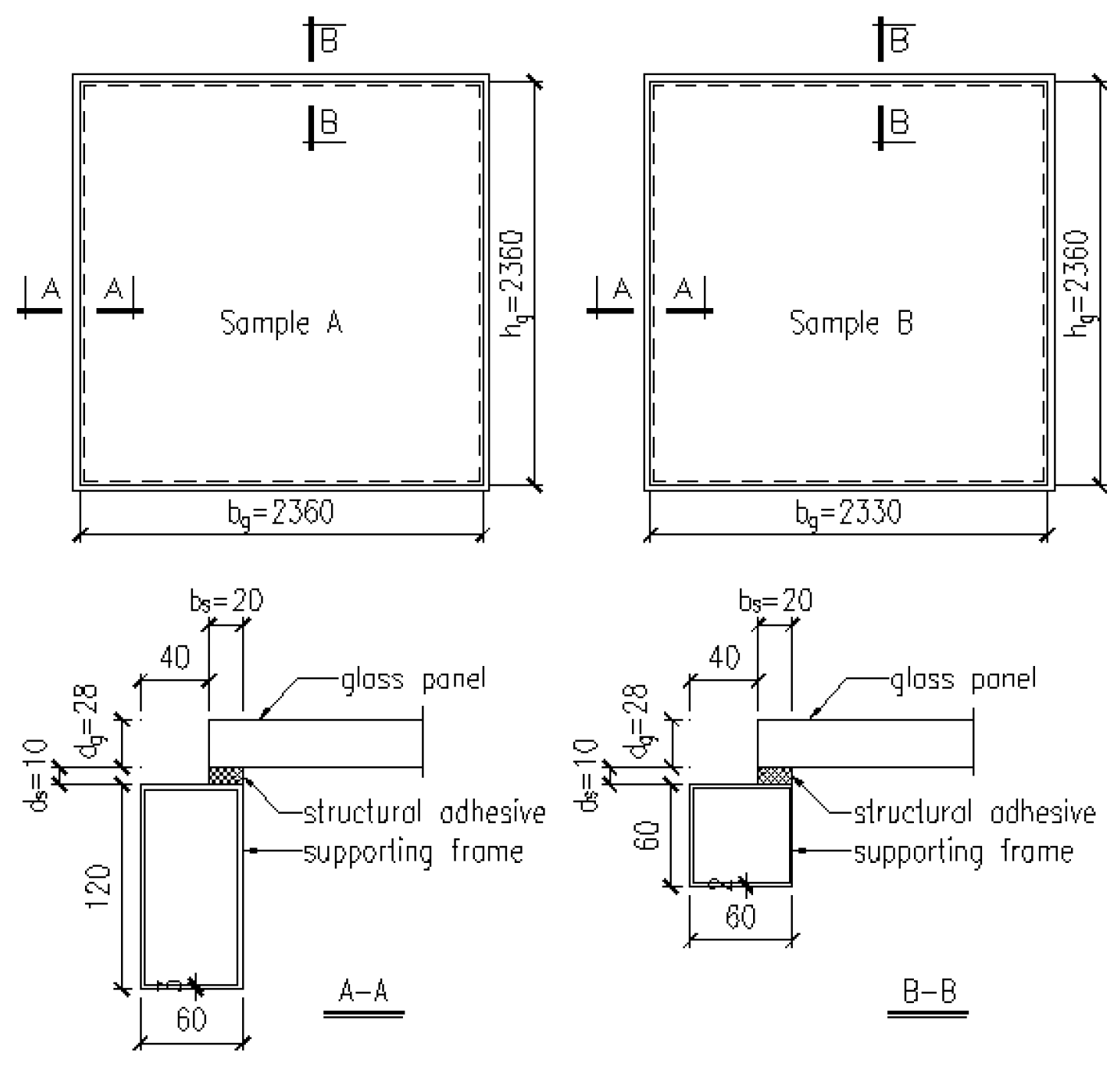
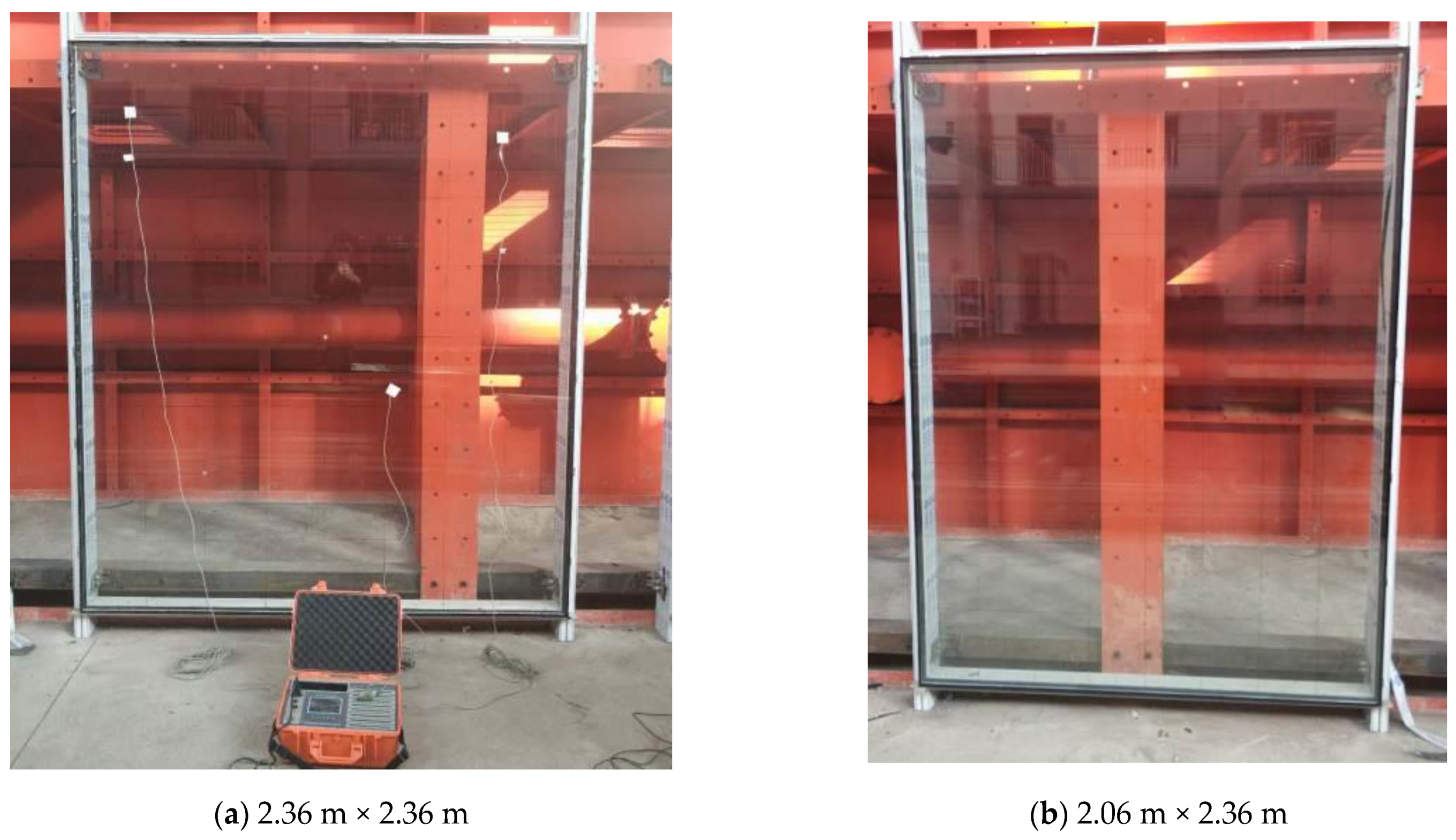
Panel units consist of a glass panel, structural sealant and a supporting frame. The difference of FE models lies in the modelling of the structural sealant and supporting frame. To illustrate the rationality of different modelling methods, the effects of the structural sealant and supporting frame on structural dynamic characteristics are studied based on the experimental results of the panel unit model.

2.1. Test Profile

The two full-sized panel units are shown in Figure 1. The glass panels of sample A and sample B are 2.36 m and 2.06 m in width, both 2.36 m in height and 28 mm in thickness, denoted by bg, hg, and dg, respectively. The panel units are bonded to the auxiliary frame with structural adhesive with a width of 20 mm and a thickness of 10 mm, denoted by bs and ds, respectively. The supporting frame of the two samples adopts an aluminum alloy box section. The cross-section size of the column frame is 60 mm × 120 mm, and the wall thickness is 3 mm. The cross-section size of the beam is 60 mm × 60 mm, and the wall thickness is 2 mm. The column was fixed on the upper and lower end on the test platform, which belongs to the State Key Laboratory of China Academy of Building Research. The picture after installation is shown in Figure 2.

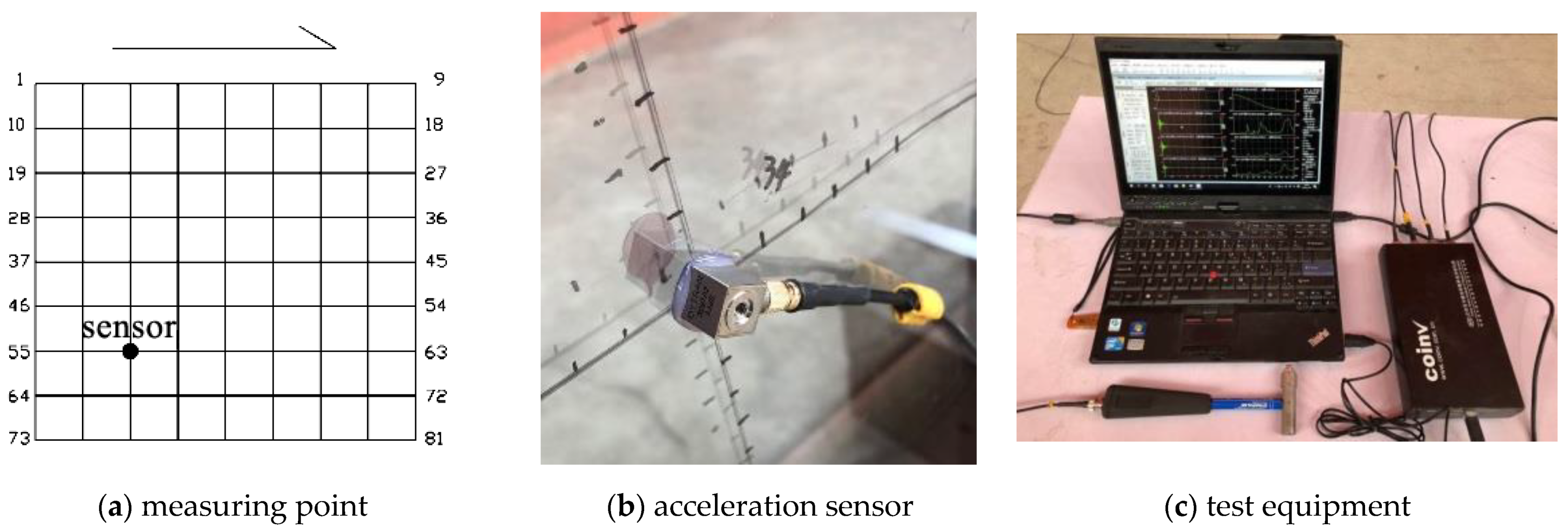
2.2. Sensor Layout and Loading Scheme

The measuring points and sensor layout of the panel units are shown in Figure 3a. Each edge was divided into 8 equal parts to form 81 cross nodes as the impulse points, which were numbered in sequence. Acceleration sensors were installed on node No. 57 (Figure 3b). Experimental modal analysis adopts the multiple input and single output (MISO) method. A force hammer is used to hit the 81 intersection points in turn, and the force signal of the hammer and the acceleration signal of the accelerometer located at node No. 57 are collected for each hit. The measured results are used to identify the natural frequency and mode of panel units by using the eigensystem realization algorithm (ERA) [19] method. The sampling frequency of the modal test was 512 Hz and the sampling time was 16 s. The acceleration sensor used in the test was DYTRAN-3097A2 and the force hammer was DYTRAN-5800B4. The data acquisition device was Oriental Institute 3018-A. The test equipment is shown in Figure 3c.

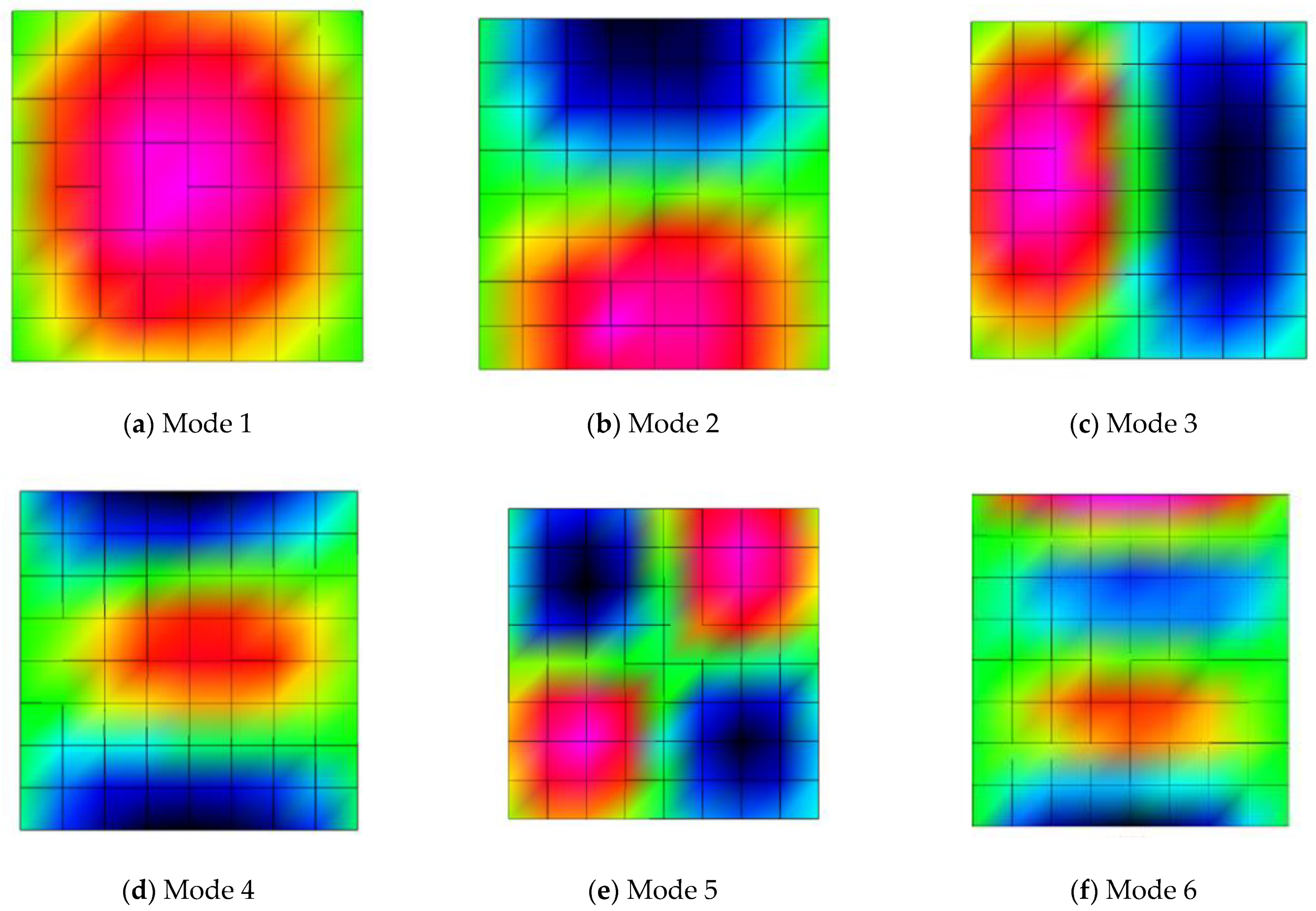
2.3. Experimental Results

Table 1 shows the first six natural frequency results identified by the ERA method for the two samples, and Figure 4 shows the first six vibration mode results identified from sample A. The modes of sample B are the same as those of sample A and will not be listed repeatedly. The first six identified vibration modes are agreed with the theoretical modes, which means those modes are not spurious. Usually, the errors of measured natural frequencies are less than 1% [20]; therefore, these measured natural frequencies are used as the basis for comparison of the calculated results of the model. In terms of the identified natural frequencies, the natural frequency of sample A is smaller than that of sample B, which is the inevitable result of sample A’s larger size compared to sample B, and the identified modes have the same rule as the theoretical modes of a rectangular plate [21], which reflects the good modal test results. The maximum difference in natural frequency between two samples is 16.241%, which reflects the influence of panel size on natural frequency. The numerical model of panel units is studied based on the test results.

3. Effect of Structural Sealant and Supporting Frame

Compared with the main structure, the panel units of the hidden frame curtain wall are small, so the influence of the main structure on the dynamic characteristics of the panel units is ignored. Panel units consist of a glass panel, structural sealant and a supporting frame. In order to study the influence of structural sealants and a supporting frame on the dynamic characteristics of panel units, the following three finite element models calculated by ANSYS are established:
Model 1: A simply supported boundary model that ignores the influence of a supporting frame and structural sealant.
Model 2: A model ignoring the influence of a supporting frame and considering the influence of structural sealant.
Model 3: A fine finite element model considering the influence of a supporting frame and structural sealant.
The three finite element models of sample A are shown in Figure 5. In the finite element model, the glass panel and supporting frame adopt the shell element, and structural sealant adopts the solid element. The physical parameters of different materials are shown in Table 2. Three finite elements models are established and conducted on the two samples of the test for calculating the first six-order natural frequencies, and the results are listed in Table 3 and Table 4.
If the influence of the supporting frame and structural sealant is ignored, the analytical solution of the natural frequency of a rectangular plate unit under a simply supported boundary is [21]:
f m n = π 2 ( m 2 b g 2 + n 2 h g 2 ) D ρ g d g
D = E g d g 3 12 ( 1 μ g 2 )
where ρ g is the density of the plate; b g is the width of the plate; h g is the height of the plate; d g is the thickness of the plate; E g is the elastic modulus of the plate; μ g is the Poisson’s ratio of the plate; m and n are natural numbers, taking different values for corresponding natural frequency values.
For comparison, the computational results of simply supported boundary solutions are also listed in Table 4. Comparing the measured natural frequencies with calculated ones show that (a) the analytical solution of a simply supported boundary is basically the same as the numerical solution of Model 1, and the difference between two solutions is less than 1%, indicating that the mesh division of the numerical calculation model is reasonable; (b) in the case of simply supported boundary conditions, sample A has a phenomenon of partial modal repetition, which occurred in orders 2 and 3, orders 5 and 6, and orders 7 and 8. Since the panel is square, the model’s rotational symmetry leads to the same natural frequency but different modes. However, for the test results, there is no repetition phenomenon, which is found under the conditions of the different cross-section of column and beam, causing the different vertical and horizontal boundary conditions of the panel. The results show that ignoring the effect of the supporting frame will result in a huge difference in the calculated natural frequencies.
In order to compare the calculation errors of different models, the natural frequency obtained from the test and the finite element model are treated as an exact and approximate solution and denoted as r* and r, respectively. Then, the relative error of the calculation results of the finite element model is:
e = | r | | r * | | r * | × 100 %
Figure 6 shows the relative errors of the calculated results of finite element models of two samples. It can be seen from the calculation results that: (a) The highest error of the natural frequency obtained by a simply supported boundary can reach more than 40%, and all results of the natural frequency obtained are greater than the measured results, which indicates that ignoring the influence of structural sealant and a supporting frame will overestimate the natural frequency of panel units; (b) considering the elastic effect of structural sealant, the error from the model 2 calculation result is significantly reduced compared to the simply supported boundary, but the error can still reach more than 20%; (c) in model 3, the influence of both structural sealant and a supporting frame is considered, and most of the calculation errors are less than 5%, showing a good calculation accuracy. The results show that the influence of structural sealant and a supporting frame on the dynamic characteristics of panel unit is not negligible, and the natural frequency of panel units of hidden frame curtain wall is less than that under a simply supported boundary condition. Other test models, such as the one in which the panel units are directly installed on the ground [13] by fixing with fixture, and another one in which the I-steel with high stiffness was adopted [14], ignored the influence of the supporting frame and concluded that the panel’s natural frequency was between the results under the simply supported and fixed boundary conditions. It does not happen in real engineering. Therefore, it is unreasonable to take the natural frequency of a simply supported boundary as the threshold value to identify the damage of sealant of the panel unit in actural engineering.

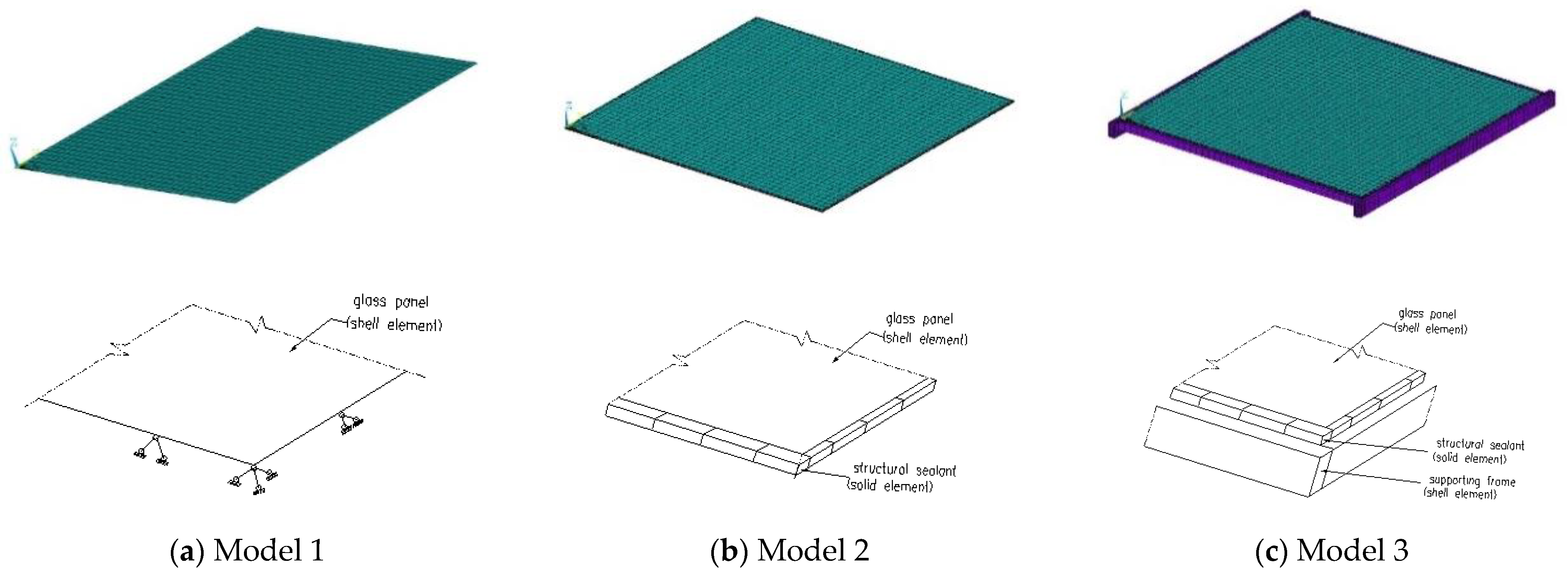
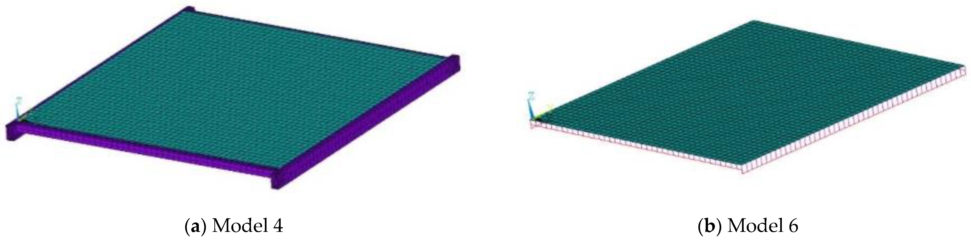
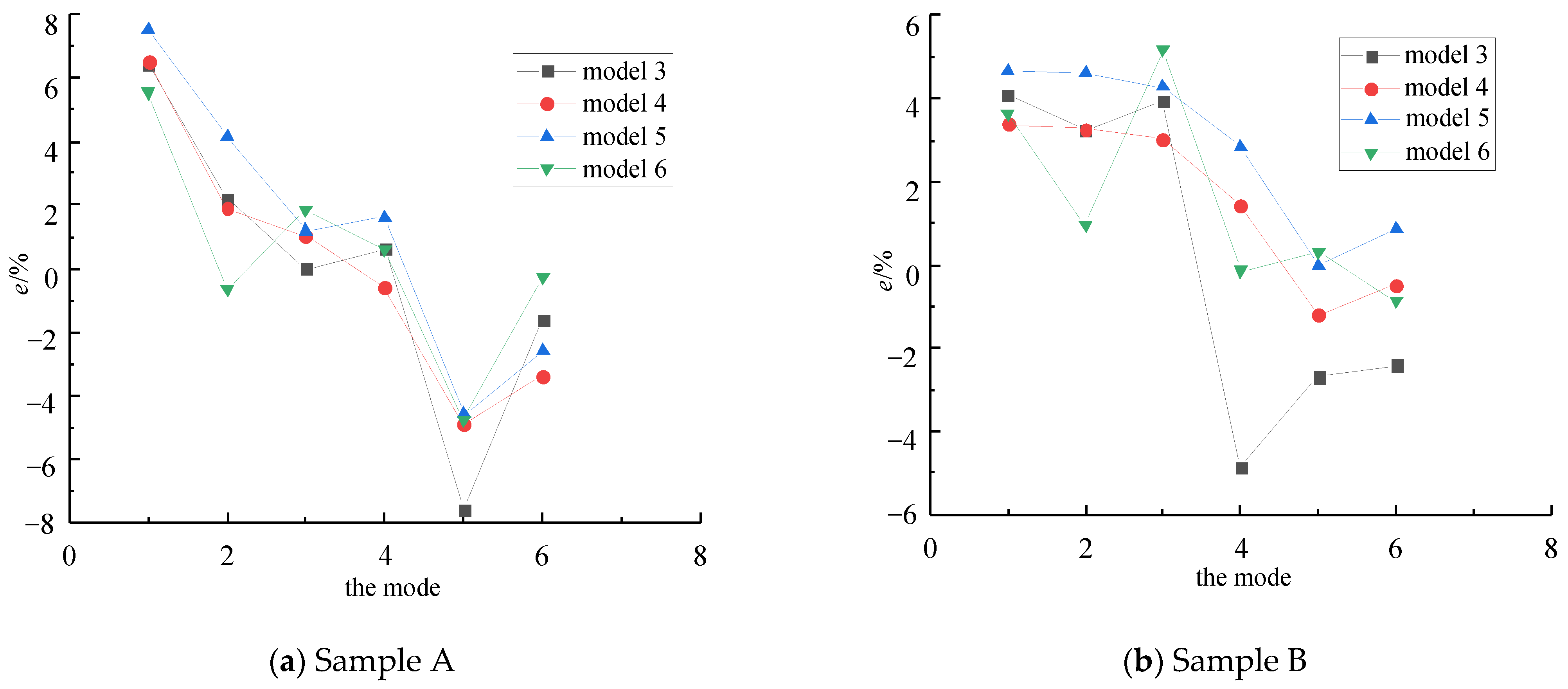
4. The Construction of Simplified Models

The solid element is used to analyze the structural sealant and the shell element is used to analyze the supporting frame. According to the boundary section in Figure 1, the structural sealant can be treated as an elastic connecting device between the glass panel and the supporting frame; that is, the load received by the panel is transferred to the supporting frame. Because the structural sealant has a certain width, it also has a certain ability to resist bending moments. Therefore, the structural sealant can be simplified into two spring models, shown in Figure 7a,b. Figure 7b ignores the influence of rotational stiffness of structural sealant. In order to calculate the stiffness coefficient of the spring, it can be known from the beam theory that the spring stiffness coefficient of unit length structure sealant can be expressed as [22]:
k z = E s b s d s
k θ = E s b s 3 3 d s
where b s and d s are the width and thickness of the structural sealant, respectively; E s is the elastic modulus of the structural sealant.
The cross-section of the column and beam of the supporting frame is much smaller than the length of the member, so it can be simplified as a beam element. Therefore, the following simplified calculation model is proposed:
Model 4: The supporting frame is a shell element, and the structural sealant is simplified as a vertical translational spring element.
Model 5: The supporting frame is a shell element, and the structural sealant is simplified as a vertical translational and rotating spring element.
Model 6: The supporting frame is a beam element, and the structural sealant is simplified as a vertical translational spring element.
The finite element models of Models 4 and 6 are shown in Figure 8. Model 4 and Model 5 differ only in spring parameters, but are completely the same in other aspects. Table 5 and Table 6 show the natural frequencies of the first six orders obtained by the simplified calculation model of the two samples. The measured natural frequencies are taken as the exact solution, and the relative error of the simplified calculation of the natural frequencies are shown in Figure 9.
By comparing the calculation results of Model 4 and Model 5, the difference in natural frequency between them is less than 1%, indicating that the rotational stiffness of structural sealant has little influence on the natural frequency of the system. Therefore, to simplify the calculation, the influence of rotational stiffness can be ignored. Based on Model 4, Model 6 further simplifies the supporting frames to beam elements; the results show that the error of the natural frequencies is less than 5% except for the first natural frequency of sample A and the third natural frequency of sample B, whose errors are slightly more than 5%. Therefore, Model 6 can be used as the simplified calculation model of hidden frame curtain wall panel units. Model 6 is simplified from Model 3, which includes 3424 shell elements and 1324 entity elements. After simplification, Model 6 includes 1840 shell elements, 176 spring elements and 172 beam elements. The degrees of freedom (DOFs) before and after simplification are 17,913 and 7341, respectively. Due to the simplification, the DOFs decreased more than 59%, and consequently reduced the computational processing time.

5. Conclusions

To clarify the main factors that influence the dynamic characteristics of the hidden frame curtain wall panel units and establish the corresponding simplified calculation model, the modal experiments are conducted on two full-scale hidden frame curtain wall panel elements, the main influencing factors on the dynamic characteristics of the panel unit are analyzed, and the simple calculation model is established in this paper. The experiment and numerical calculation results can draw the following conclusions:
(1)
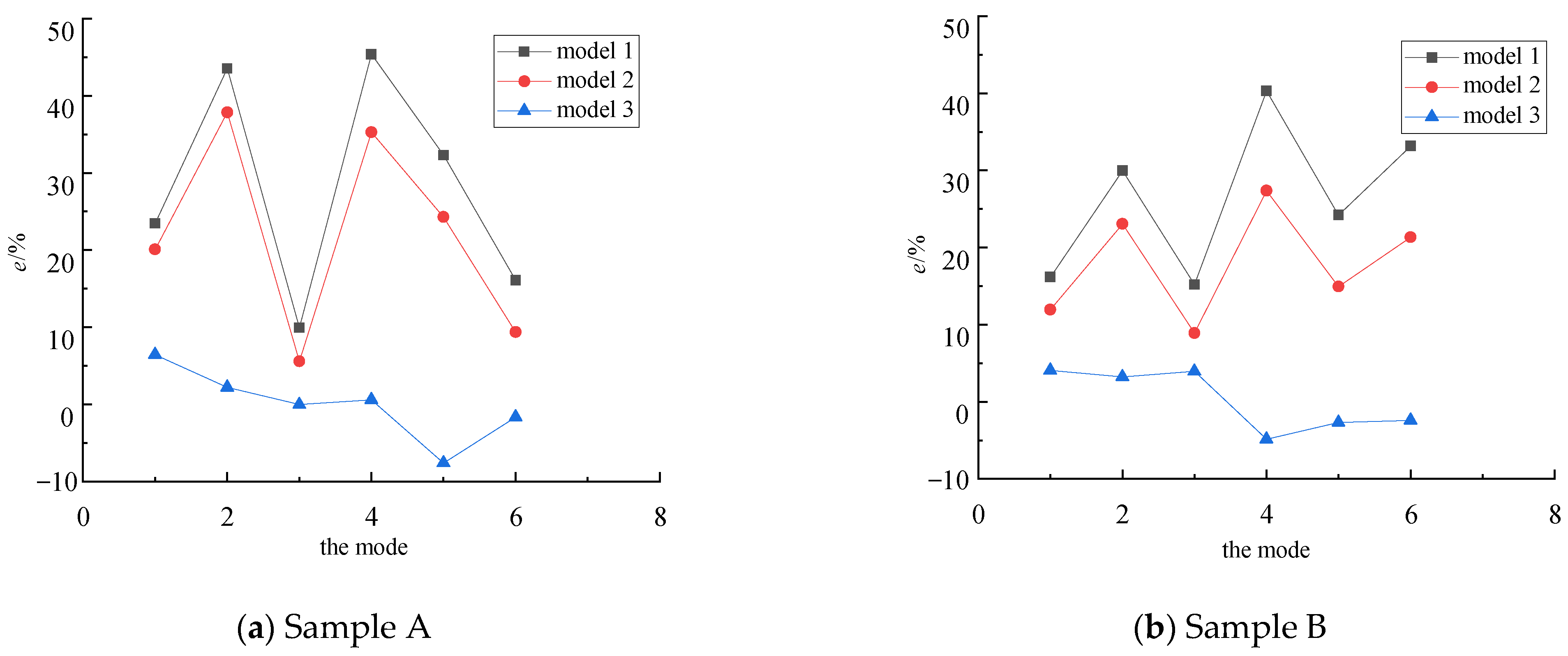
The simply supported boundary model, which ignores both the influence of the structural sealant and the supporting frames, will overestimate the error of the inherent frequency of the panel unit by more than 40%. A model ignoring only the influence of supporting frames will overestimate the natural frequency by 20% as above. Therefore, the influence of the structural sealant and the supporting frame on the dynamic characteristics analysis of the hidden frame glass curtain wall panel units should not be neglected.
(2)
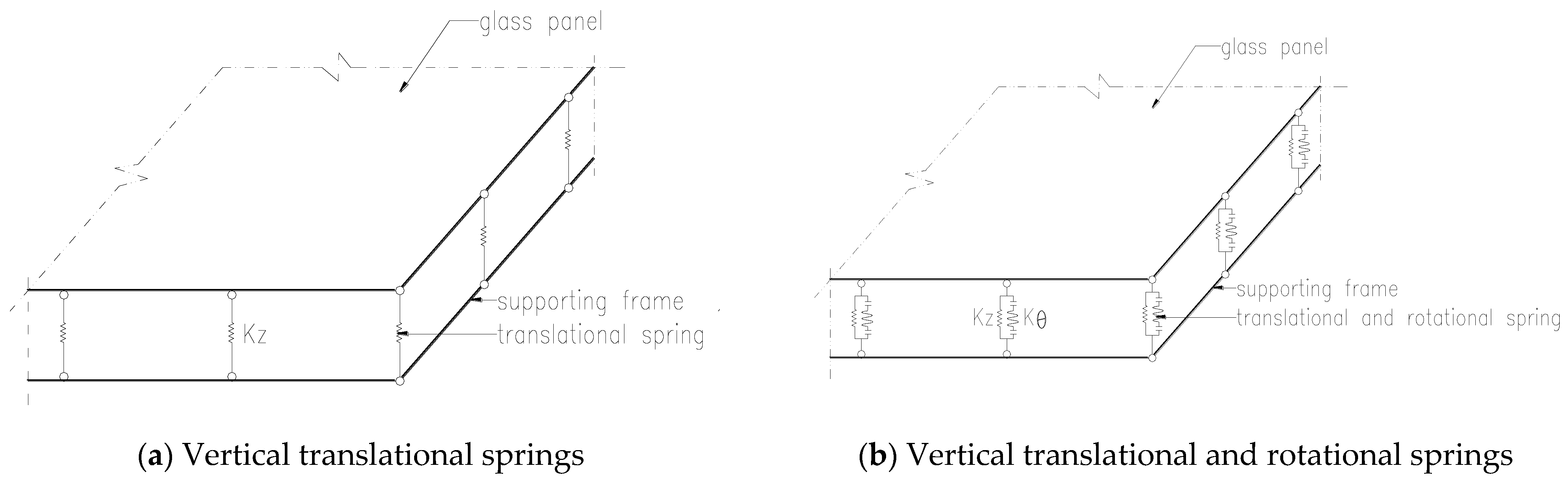
Since the main constraint of the structural sealant on the glass panel is a vertical translational effect other than the rotation effect, the structural sealant can be simplified as a vertical translational spring.
(3)
Using the simplified calculation model of the shell element of the glass panel, the spring element of the structural sealant and the beam element of the supporting frame, the relative error of the calculated natural frequencies is mostly less than 5%, showing a good calculation accuracy.

Author Contributions

Writing—Review and Editing and Investigation, X.Z. and C.X.; Conceptualization and Methodology, D.P.; Writing—Review and Editing, X.F.; Formal analysis, S.T. All authors have read and agreed to the published version of the manuscript.

Funding

This research received no external funding.

Institutional Review Board Statement

Not applicable.

Informed Consent Statement

Not applicable.

Data Availability Statement

Not applicable.

Conflicts of Interest

The authors declare no conflict of interest.

References

  1. Huang, X.K.; Zhao, X.A.; Liu, J.J.; Liu, G. Development of Building Curtain Walling Techniques in China over 30 Years. Build. Sci. 2013, 29, 80–88. (In Chinese) [Google Scholar]
  2. Boscato, G.; Reccia, E.; Cecchi, A. Non-destructive experimentation: Dynamic identification of multi-leaf masonry walls damaged and consolidated. Compos. Part B Eng. 2018, 133, 145–165. [Google Scholar] [CrossRef]
  3. Marques, D.; Flor, F.R.; de Medeiros, R.; Pagani, J.; do Carmo Pagani Junior, C.; Volnei, T. Structural Health Monitoring of Sandwich Struc-tures Based on Dynamic Analysis. Lat. Am. J. Solids Struct. 2017, 15, e58. [Google Scholar] [CrossRef] [Green Version]
  4. Quqa, S.; Landi, L.; Diotallevi, P.P. Modal assurance distribution of multivariate signals for modal identification of time-varying dynamic systems. Mech. Syst. Signal Process. 2021, 148, 107136. [Google Scholar] [CrossRef]
  5. Anjneya, K.; Roy, K. Response Surface-Based Model Updating in Structural Damage Identification Using Dynamic Responses. Structures 2021, 29, 1047–1058. [Google Scholar] [CrossRef]
  6. Meisam, G.; Abdul, R.H.; Zubaidah, I.; Khaled, G. Recent Developments in Damage Identification of Structures Using Data Mining. Lat. Am. J. Solids Struct. 2017, 14, 2373–2401. [Google Scholar]
  7. Yu, Y.; Liu, T.; Zhang, Q.L.; Yang, B. Wind-Induced Response of an L-Shaped Cable Support Glass Curtain Wall. Shock Vib. 2017, 2017, 1–16. [Google Scholar] [CrossRef] [Green Version]
  8. Reyes, J.C.; Correal, J.F.; Mancera, A.G.; Echeverry, J.S.; Gómez, J.S.; Sandoval, J.D.; Ángel, C.C. Experimental evaluation of permeable cable-supported facades subjected to wind and earthquake loads. Eng. Struct. 2020, 214, 110679. [Google Scholar] [CrossRef]
  9. Huang, B.F.; Chen, S.M.; Lu, W.S.; Mosalam, K.M. Seismic demand and experimental evaluation of the nonstructural building curtain wall: A review. Soil Dyn. Earthq. Eng. 2017, 100, 16–33. [Google Scholar] [CrossRef]
  10. Aiello, C.; Caterino, N.; Maddaloni, G.; Bonati, A.; Franco, A.; Occhiuzzi, A. Experimental and numerical investigation of cyclic response of a glass curtain wall for seismic performance assessment. Constr. Build. Mater. 2018, 187, 596–609. [Google Scholar] [CrossRef]
  11. Ren, W.X.; Peng, X.L. Baseline finite element modeling of a large span cable-stayed bridge through field ambient vibration tests. Comput. Struct. 2005, 83, 536–550. [Google Scholar] [CrossRef]
  12. Zare, H.A.; Ghodrati, A.G.; Jafarian, A.M.; Seyed, R.; Seyed, A.; Ghadimi, H.A. Baseline updating method for structural damage identification using modal residual force and grey wolf optimization. Eng. Optim. 2020, 52, 549–566. [Google Scholar] [CrossRef]
  13. Liu, X.G.; Bao, Y.W. Safety evaluation for frame supported glass curtain wall based on modal frequency change. Shen-Yang Univ. Technol. 2011, 33, 595–600. (In Chinese) [Google Scholar]
  14. Huang, Z.D.; Xie, M.W.; Song, H.K.; Du, Y. Modal analysis related safety-state evaluation of hidden frame supported glass curtain wall. J. Build. Eng. 2018, 20, 671–678. [Google Scholar] [CrossRef]
  15. Huang, Z.D.; Xie, M.W.; Zhao, J.H.; Du, Y.; Song, H.K. Rapid evaluation of hidden frame supported glass curtain wall safety state based on remote vibration measurement. J. Build. Eng. 2018, 19, 91–97. [Google Scholar] [CrossRef]
  16. Pan, D.G.; Jiang, K.; Zhang, X.C.; Huang, Y.; Caddemi, S. Sealants Delamination Detection of Structural Sealant Glazing Systems Based on Driving-point Accelerance. Shock Vib. 2020, 1, 7260438. [Google Scholar] [CrossRef]
  17. Zheng, H.; Zhang, X.C.; Wang, H.T.; Pan, D.G.; Jiang, K. Damage detection of bonded structure of building glass curtain wall based on origin FRF. J. Vib. Shock 2021, 40, 289–298. (In Chinese) [Google Scholar]
  18. Shi, B.J.; Yin, X.J.; Zhang, R.J.; Song, S.J. Experimental analysis and numerical simulation of mechanical behavior of glass curtain walls. J. Shandong Jianzhu Univ. 2006, 21, 474–479. (In Chinese) [Google Scholar]
  19. Juang, J.N.; Pappa, R.S. An eigensystem realization algorithm for modal parameter identification and model reduction. J. Guid. Control Dyn. 1985, 8, 620–627. [Google Scholar] [CrossRef]
  20. Cao, Z.Y. Vibration Theory of Plates and Shells; Railway Publishing House: Beijing, China, 1989. (In Chinese) [Google Scholar]
  21. Mottershead, J.E.; Friswell, M.I. Model updating in structural dynamics: A survey. J. Sound Vib. 1993, 167, 347–375. [Google Scholar] [CrossRef]
  22. Pan, D.G.; Zhang, A.Q. Structural Mechanics (I); TsingHua University Publishing House: Beijing, China, 2014. (In Chinese) [Google Scholar]
Figure 1. Dimensions of panel units.
Applsci 12 04224 g001
Figure 2. Photo of test specimen.
Applsci 12 04224 g002
Figure 3. Impulse points and field photos of modal recognition.
Applsci 12 04224 g003
Figure 4. The first six measured modal shapes of panel units.
Applsci 12 04224 g004
Figure 5. Finite element model of panel unit.
Applsci 12 04224 g005
Figure 6. Relative error of natural frequency calculated by finite element model.
Applsci 12 04224 g006
Figure 7. Boundary section diagram.
Applsci 12 04224 g007
Figure 8. Simplified calculation model.
Applsci 12 04224 g008
Figure 9. Relative error of natural frequency of simplified model.
Applsci 12 04224 g009
Table 1. The first six-order natural frequencies identified by modal test (Hz).
Sample123456
A5.63712.13415.84419.15826.39930.088
B6.73013.83318.36922.31028.17832.663
Difference(%)16.241 12.282 13.746 14.128 6.313 7.884
Table 2. Physical parameters of materials.
MaterialDensity (kg/m3)Elastic Modulus(Gpa)Poisson’s Ratio
Glass2500720.20
Aluminum2800700.33
Structural adhesive13500.0010.45
Table 3. Calculation results of natural frequency of sample A.
No. of ModeMeasured ValuesEquation (1)Model 1Model 2Model 3
15.6376.956 (m = 1, n = 1)6.9586.775.999
212.13417.391 (m = 1, n = 2)17.42716.7312.401
315.84417.391 (m = 2, n = 1)17.42716.7315.841
419.15827.826 (m = 2, n = 2)27.87925.9219.272
526.39934.782 (m = 2, n = 3)34.98232.8124.390
630.08834.782 (m = 3, n = 2)34.98232.9129.594
Note: the values in the parentheses are m and n in Equation (1).
Table 4. Calculation results of natural frequency of sample B.
No. of ModeMeasured ValuesEquation (1)Model 1Model 2Model 3
16.7307.816 (m = 1, n = 1)7.8177.5347.005
213.83317.957 (m = 1, n = 2)17.98117.02614.282
318.36921.125 (m = 2, n = 1)21.15920.00719.095
422.31031.266 (m = 2, n = 2)31.30628.42121.226
528.17834.858 (m = 2, n = 3)34.99932.38727.420
632.66343.307 (m = 3, n = 2)43.49639.63831.877
Note: the values in the parentheses are m and n in Equation (1).
Table 5. Calculation results of simplified model for sample A.
OrderMeasured ValuesModel 4Model 5Model 6
15.6376.0036.0635.951
212.13412.36512.64112.056
315.84416.00716.03216.136
419.15819.04419.46819.269
526.39925.09925.18125.145
630.08829.06629.30230.001
Table 6. Calculation results of simplified model for sample B.
OrderMeasured ValuesModel 4Model 5Model 6
16.7306.95777.04396.975
213.83314.28614.47213.965
318.36918.92419.15319.317
422.31022.6322.94122.278
528.17827.83828.17228.264
632.66332.50732.94132.381
Publisher’s Note: MDPI stays neutral with regard to jurisdictional claims in published maps and institutional affiliations.

