
The Influence of Track Irregularity in Front of the Turnout on the Dynamic Performance of Vehicles


Abstract
:1. Introduction
2. Numerical Approach
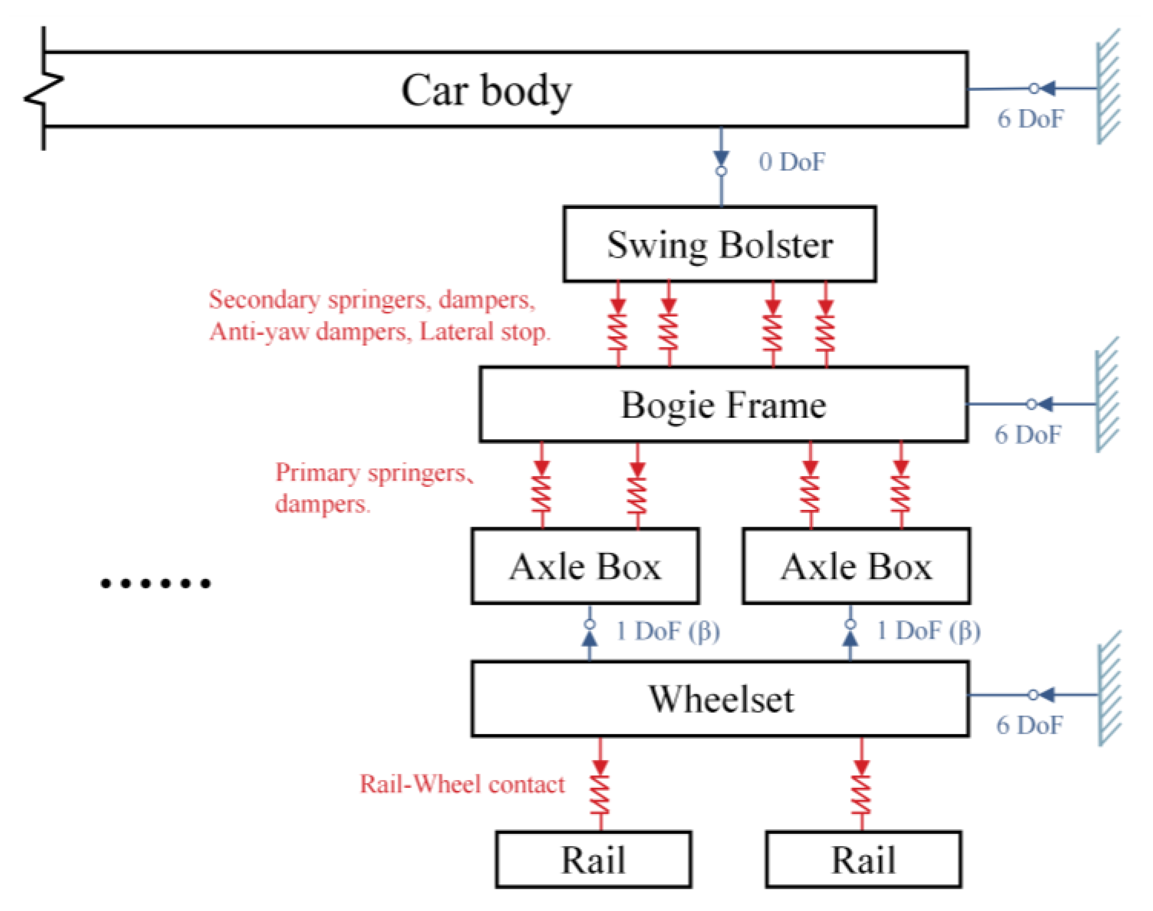
2.1. Vehicle Model
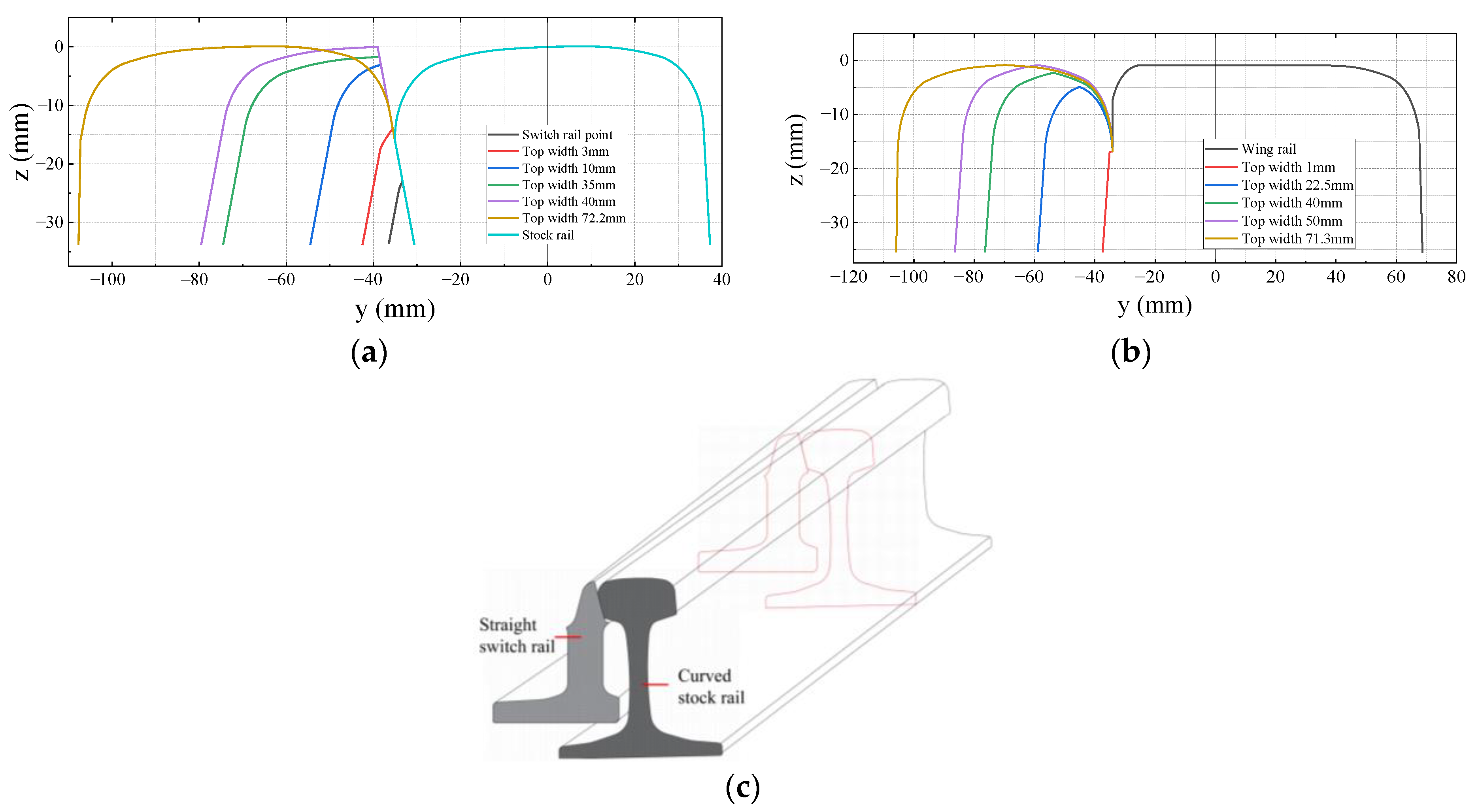
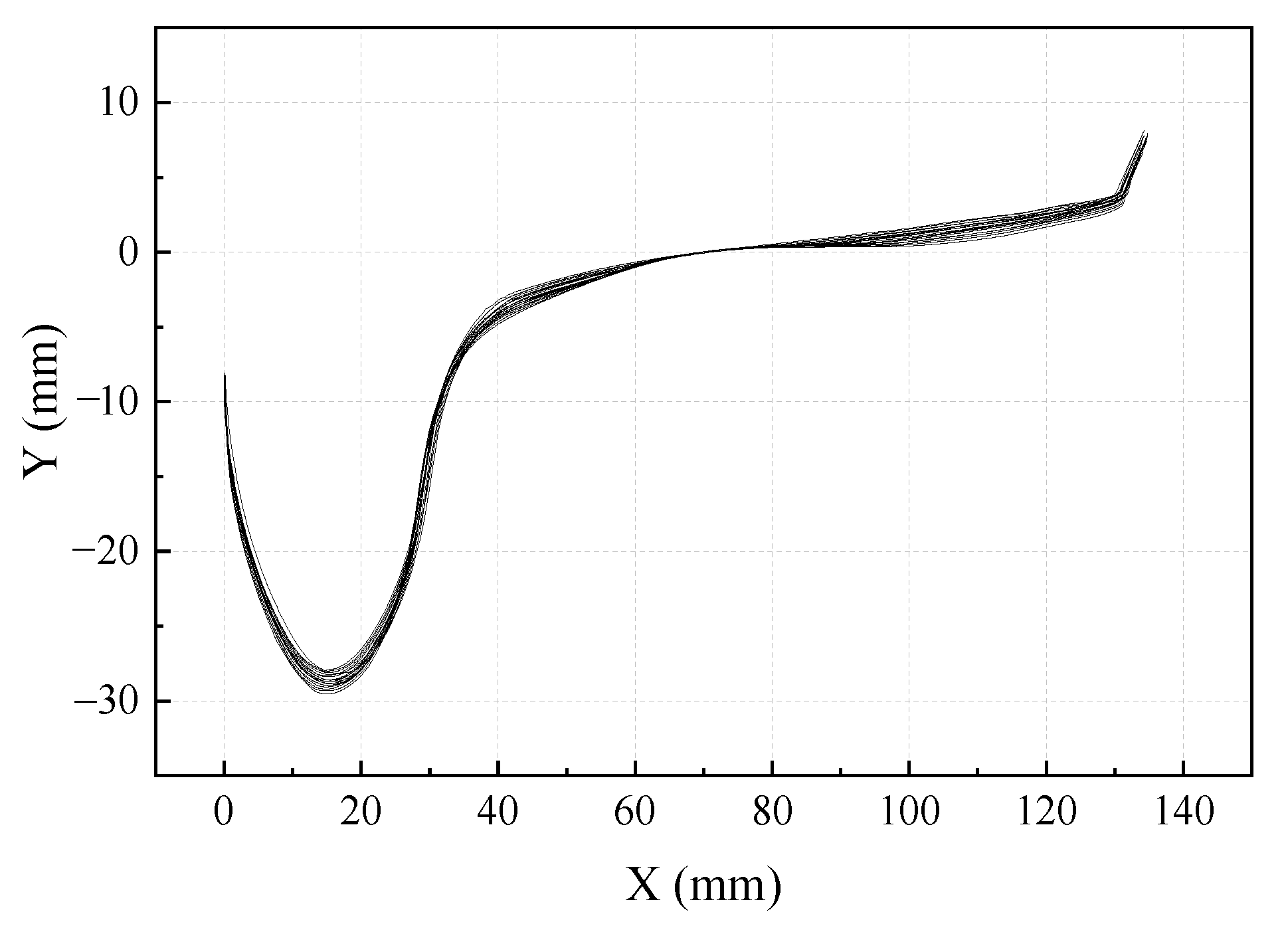
2.2. Turnout Model
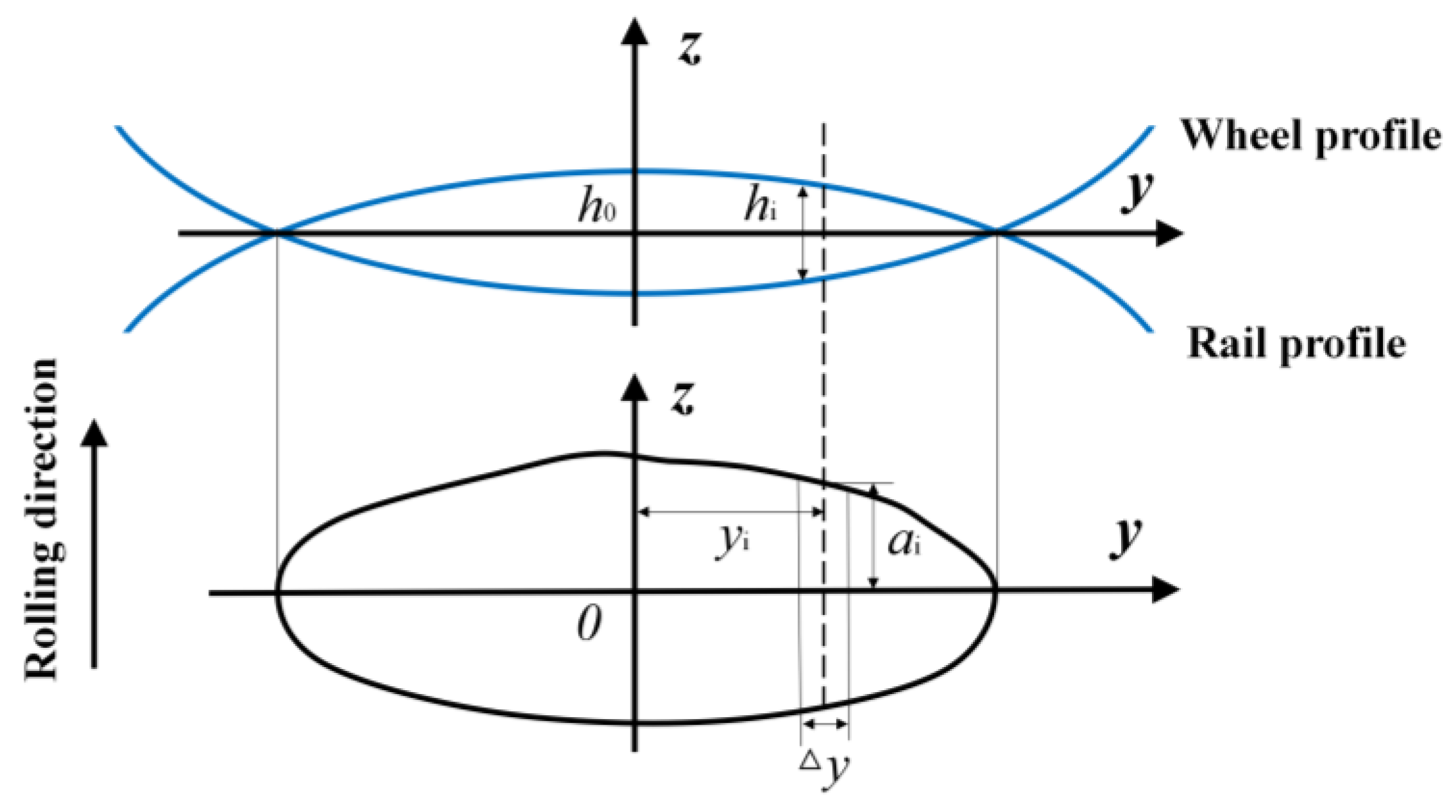
2.3. Wheel-Rail Contact Model
2.4. Vehicle-Turnout-Track Coupling
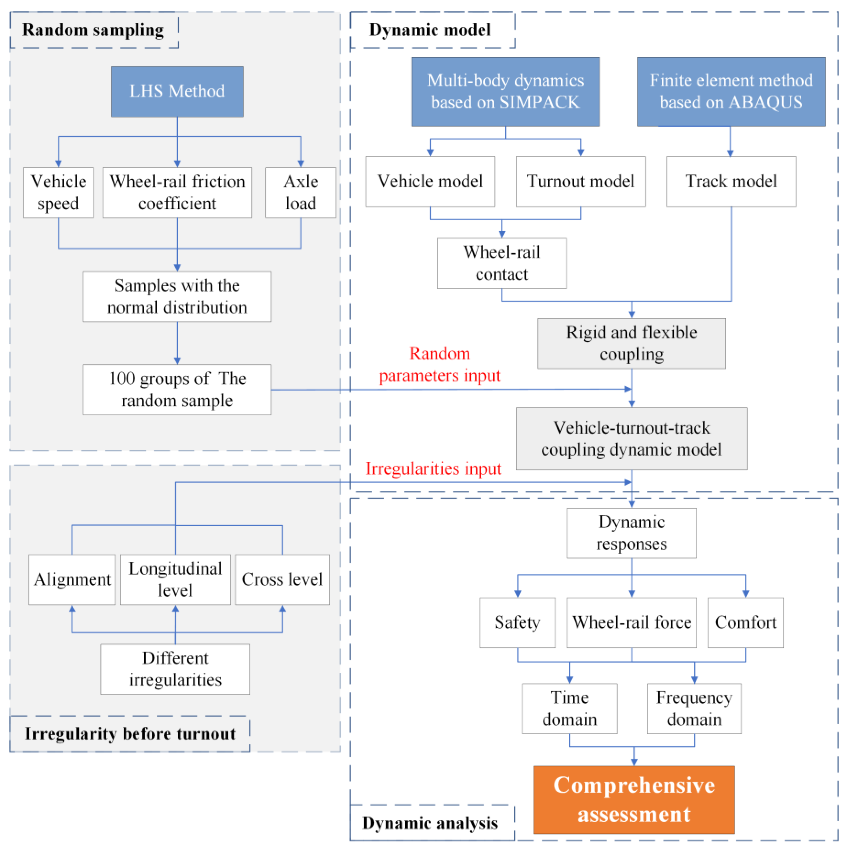
3. Random Sampling Method
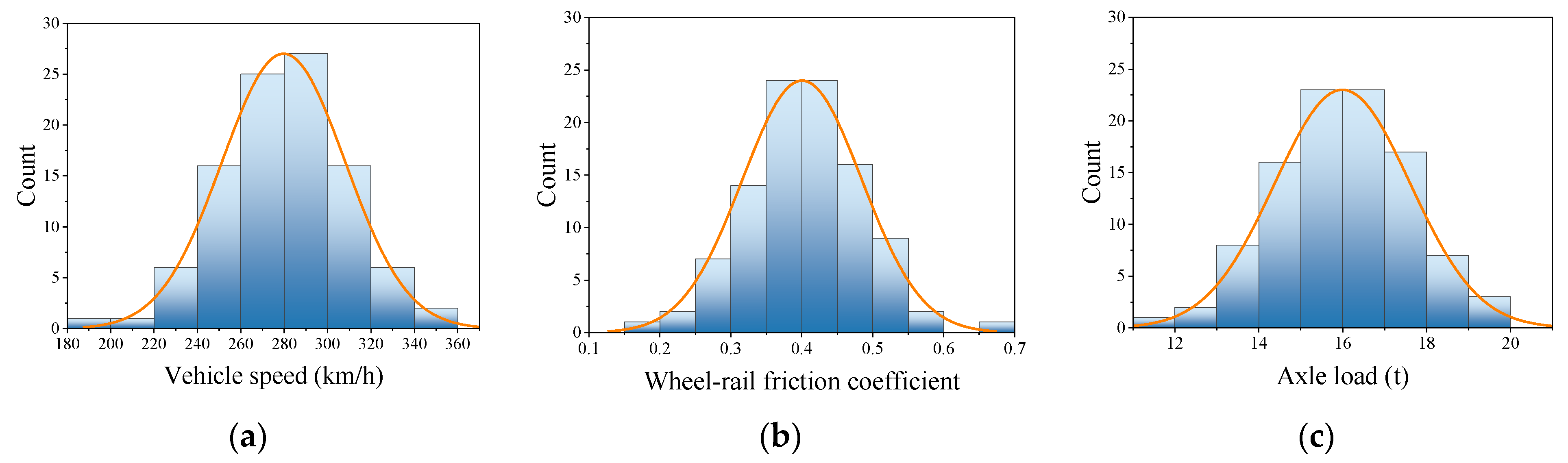
3.1. Latin Hypercube Sampling method
3.2. Calculation Process
4. Result Analysis
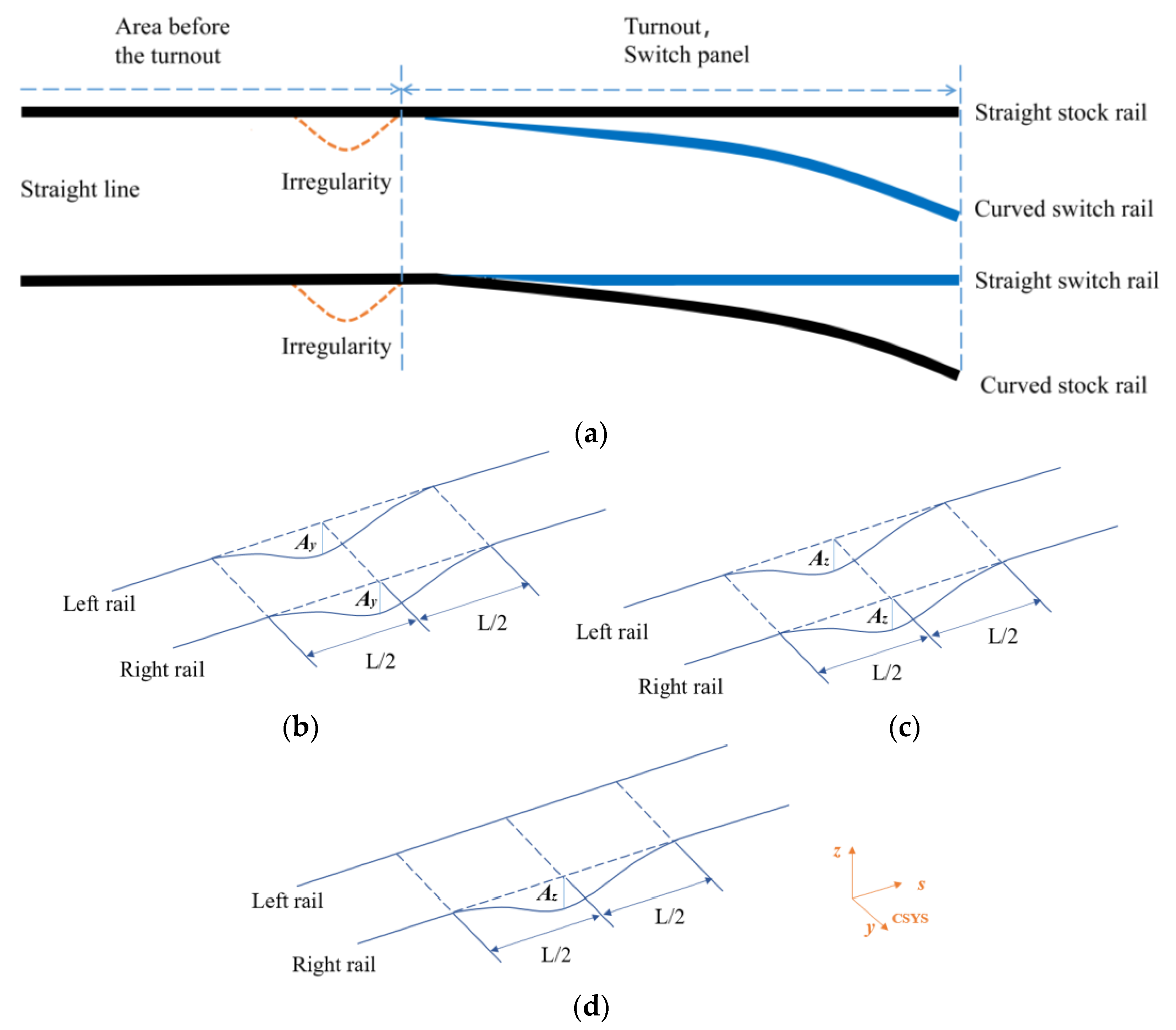
4.1. Simulation of Track Irregularity
4.2. Influence of Different Irregularities
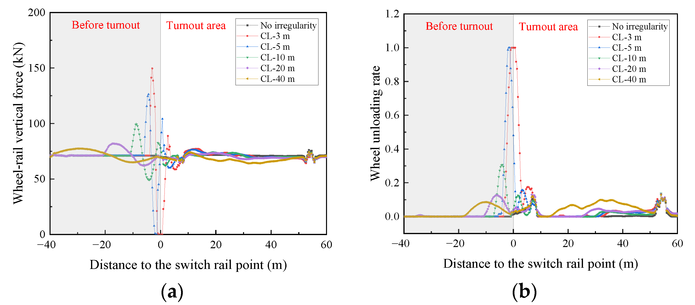
4.2.1. Analysis of the Maximum in Dynamic Indicators
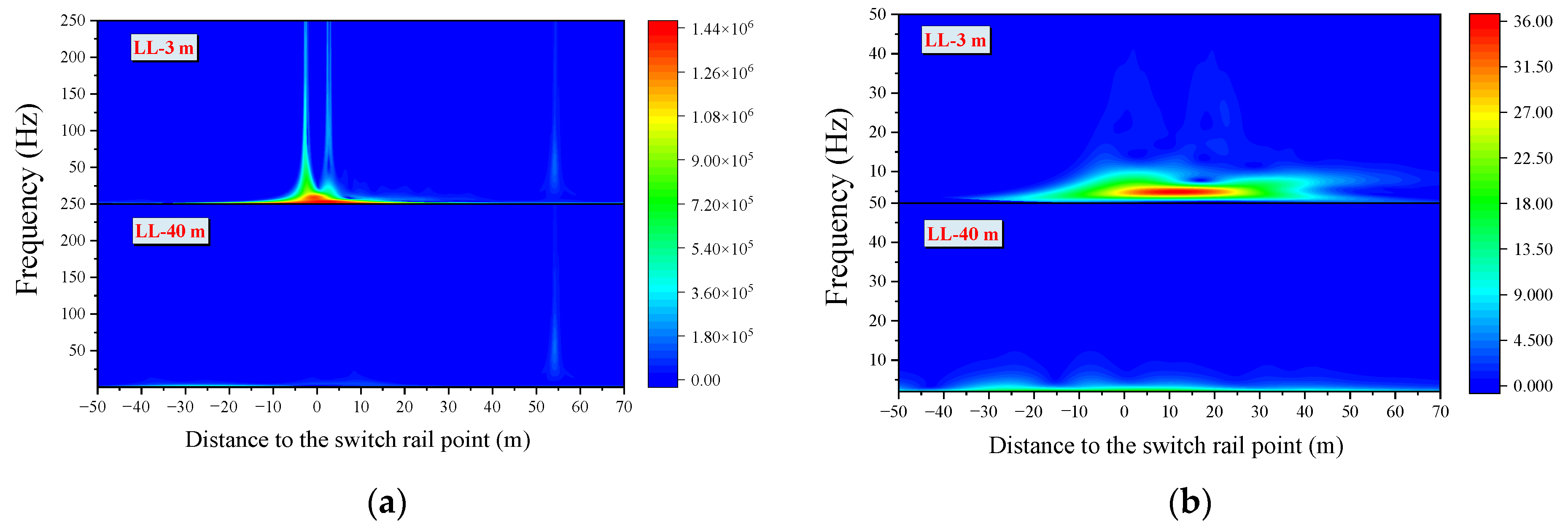
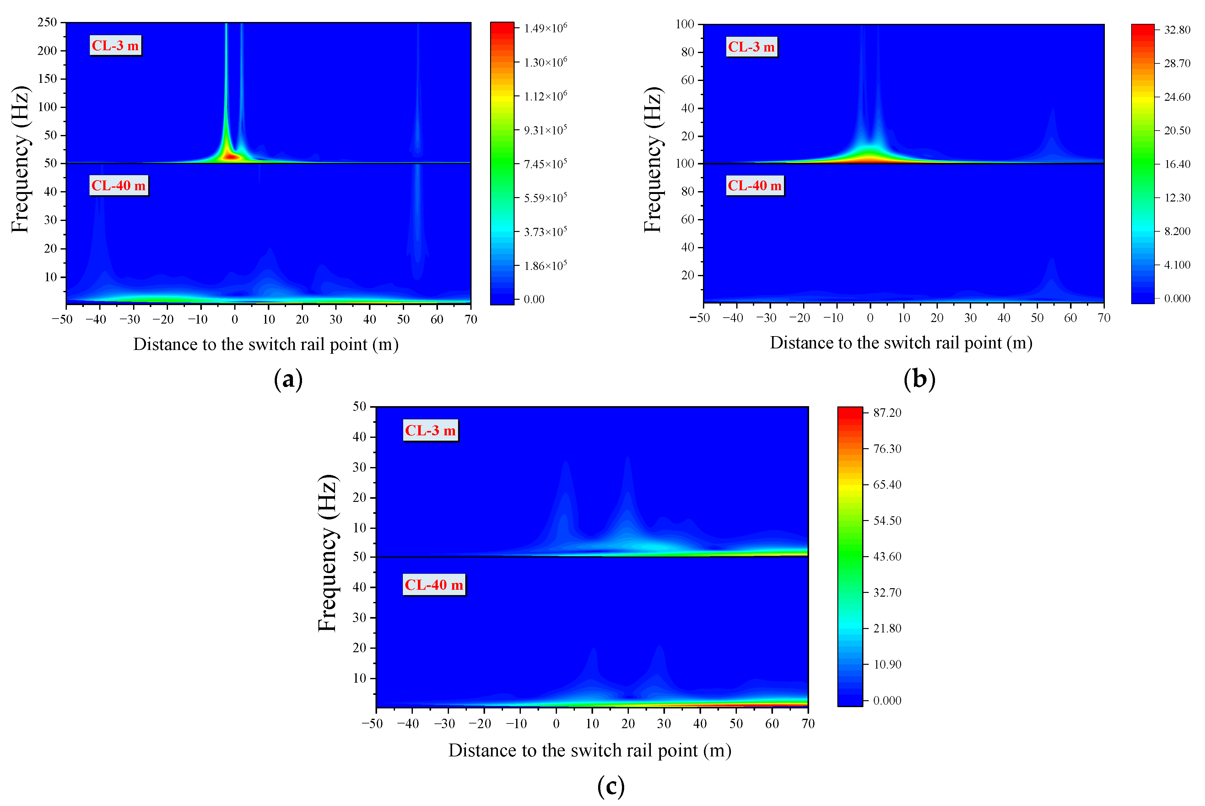
4.2.2. Time-Frequency Analysis
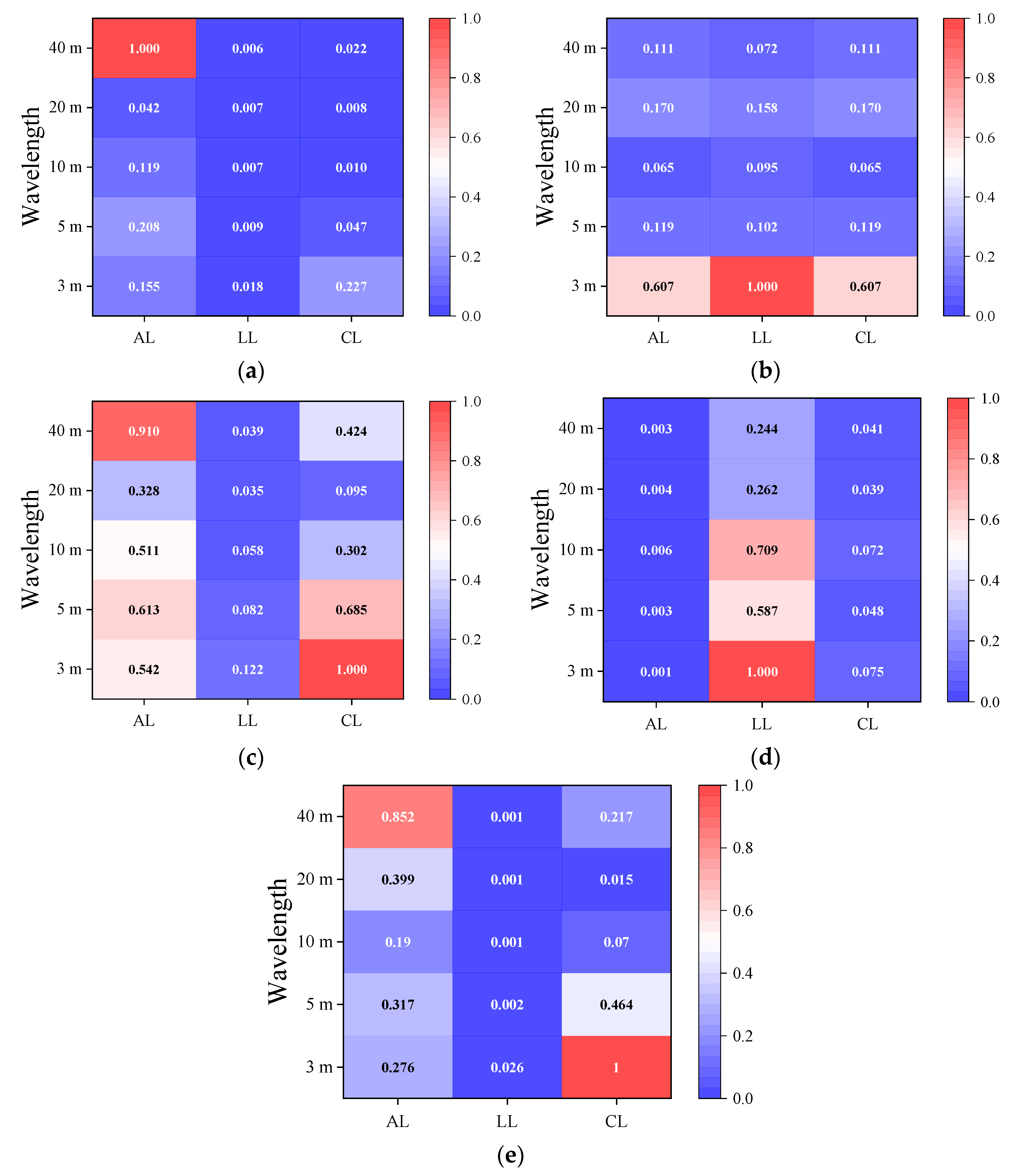
4.3. Comprehensive Assessment of Different Irregularities on Vehicle Dynamics
5. Conclusions and Future Works
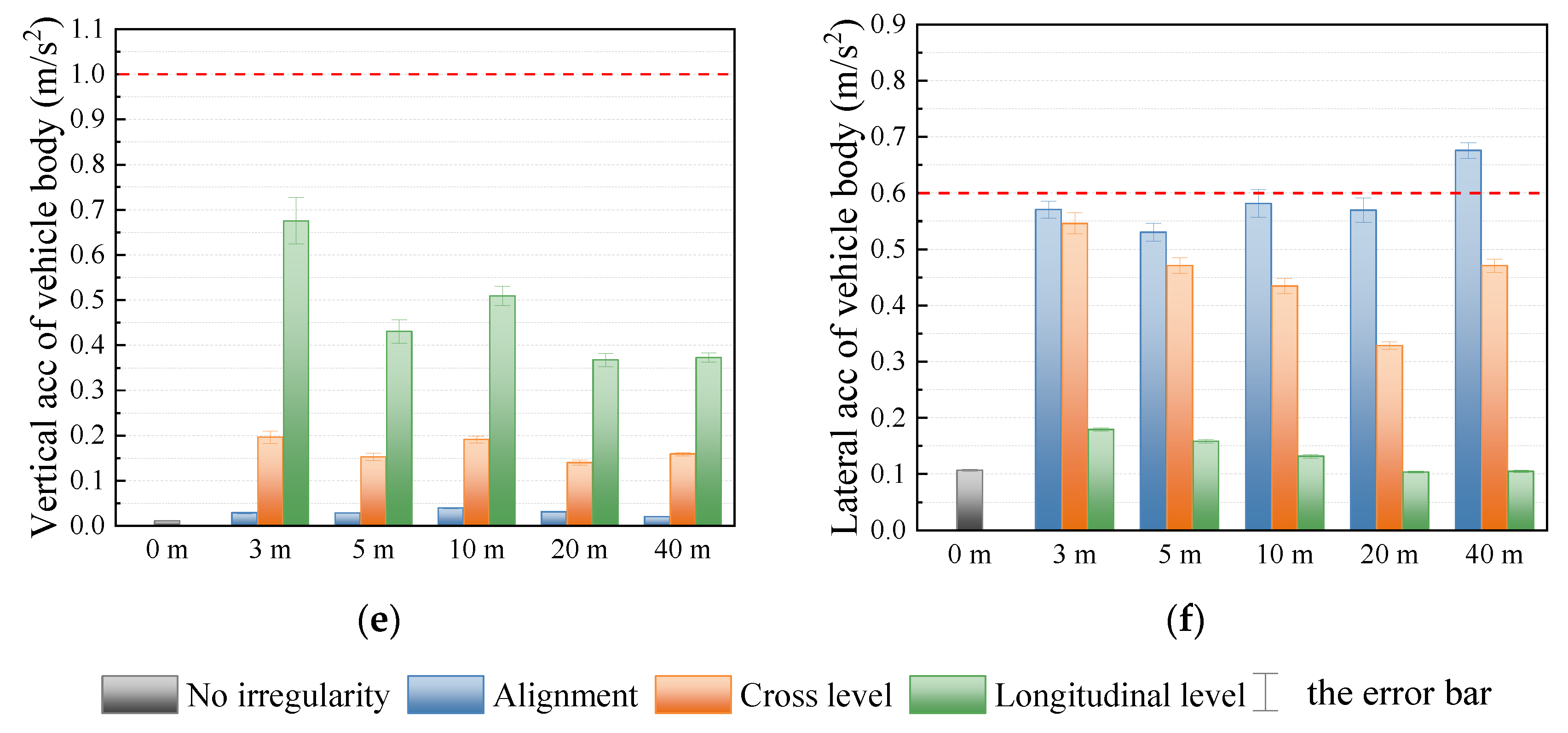
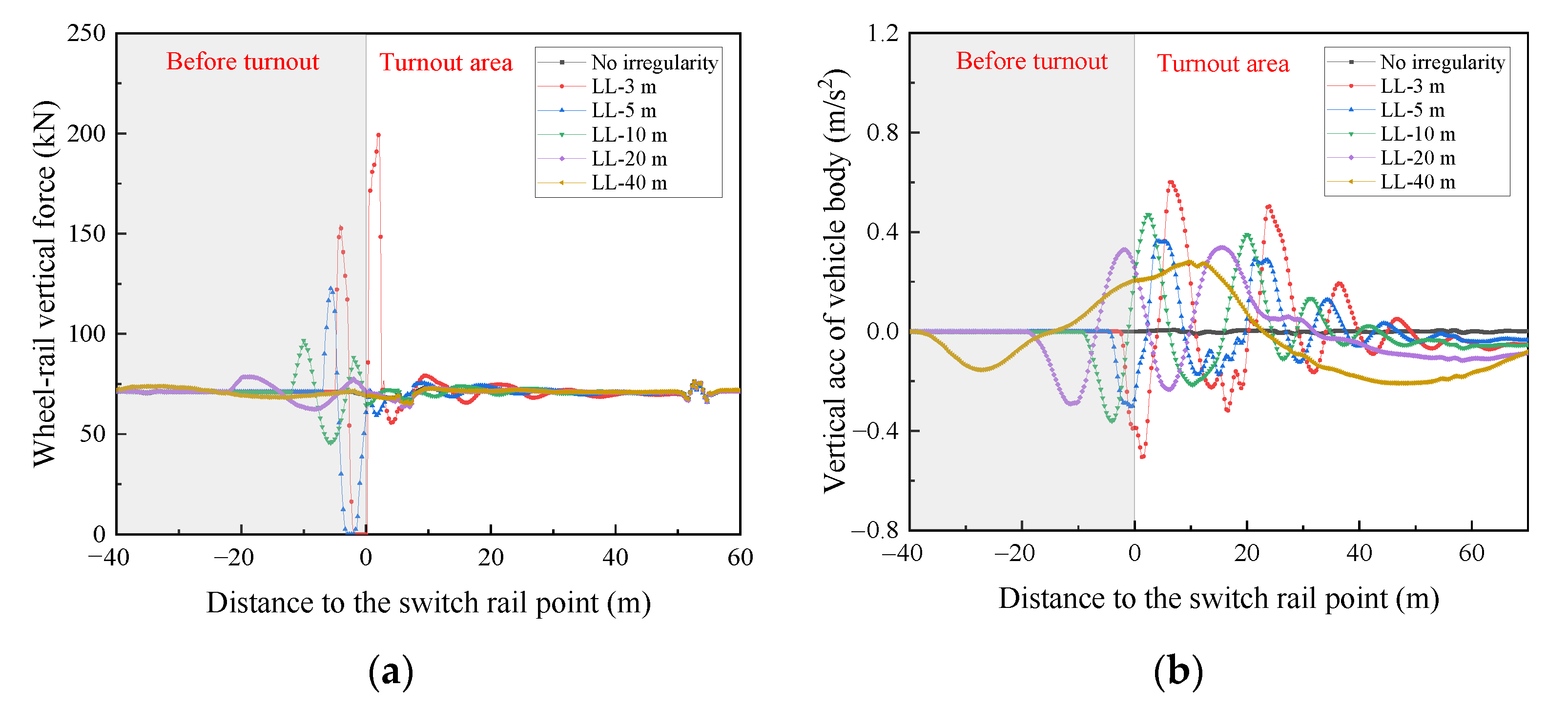
- The alignment irregularity in front of the turnout mainly affects the wheelset lateral force and lateral acceleration of the vehicle body; the irregularity of the longitudinal level in front of the turnout mainly affects the wheel-rail vertical force, wheel unloading rate, and vertical acceleration of vehicle body, and the irregularities of the cross level in front of the turnout mainly affect the wheel unloading rate and lateral acceleration of the vehicle body.
- The dynamic performance of the vehicle is most sensitive to short-wavelength irregularities in front of the turnout. Short wavelength irregularities are more likely to cause a greater wheel-rail force and wheel load reduction, resulting in a greater safety risk. Thus, special attention should be given to short-wavelength irregularities in front of the turnout during maintenance.
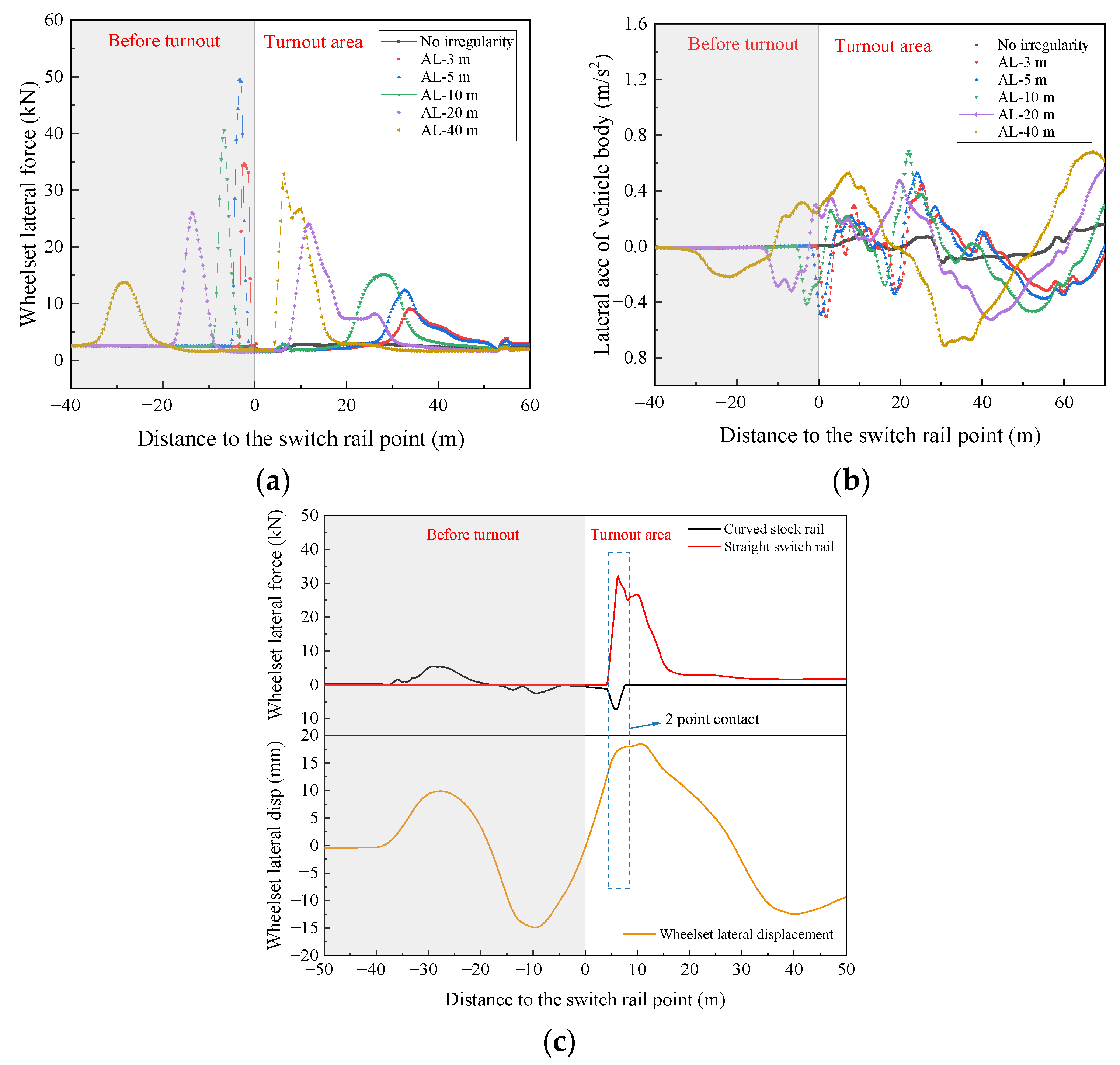
- Another interesting aspect is that the alignment irregularity with a long wavelength (40 m) has a significant effect on the wheelset lateral force and lateral acceleration of the vehicle body, which is caused by the two-point contact between the wheel and rail.
- The frequency range of the effect of the irregularities in front of the turnout on the wheel-rail force, safety indicators, and accelerations of the vehicle are mainly below 200 Hz, 50 Hz, and 20 Hz, respectively, according to the frequency analysis.
- The comprehensive assessment of different irregularities in front of the turnout from time-frequency analysis represents a quantitative and intuitive reflection of the effect of the irregularity on the dynamic indicators, which provide a reference for maintenance.
Author Contributions
Funding
Institutional Review Board Statement
Informed Consent Statement
Data Availability Statement
Conflicts of Interest
References
- Muñoz, S.; Ros, J.; Urda, P.; Escalona, J.L. Estimation of lateral track irregularity using a Kalman filter. Experimental validation. J. Sound Vib. 2021, 504, 116122. [Google Scholar] [CrossRef]
- Connolly, D.; Kouroussis, G.; Laghrouche, O.; Ho, C.; Forde, M. Benchmarking railway vibrations–Track, vehicle, ground and building effects. Constr. Build. Mater. 2015, 92, 64–81. [Google Scholar] [CrossRef] [Green Version]
- Kassa, E.; Nielsen, J. Dynamic interaction between train and railway turnout: Full-scale field test and validation of simulation models. Veh. Syst. Dyn. 2008, 46, 521–534. [Google Scholar] [CrossRef]
- Nicklisch, D.; Kassa, E.; Nielsen, J.; Ekh, M.; Iwnicki, S. Geometry and stiffness optimization for switches and crossings, and simulation of material degradation. Proc. Inst. Mech. Eng. Part F J. Rail Rapid Transit 2010, 224, 279–292. [Google Scholar] [CrossRef] [Green Version]
- Lai, J.; Xu, J.; Wang, P.; Yan, Z.; Wang, S.; Chen, R.; Sun, J. Numerical investigation of dynamic derailment behavior of railway vehicle when passing through a turnout. Eng. Fail. Anal. 2020, 121, 105132. [Google Scholar] [CrossRef]
- Karis, T.; Berg, M.; Stichel, S. Analysing the correlation between vehicle responses and track irregularities using dynamic simulations and measurements. Proc. Inst. Mech. Eng. Part F J. Rail Rapid Transit 2019, 234, 170–182. [Google Scholar] [CrossRef]
- Karis, T.; Berg, M.; Stichel, S.; Li, M.; Thomas, D.; Dirks, B. Correlation of track irregularities and vehicle responses based on measured data. Veh. Syst. Dyn. 2017, 56, 967–981. [Google Scholar] [CrossRef]
- Choi, I.I.-Y.; Um, J.-H.; Lee, J.S.; Choi, H.-H. The influence of track irregularities on the running behavior of high-speed trains. Proc. Inst. Mech. Eng. Part F J. Rail Rapid Transit 2012, 227, 94–102. [Google Scholar] [CrossRef]
- Cantero, D.; Basu, B. Railway infrastructure damage detection using wavelet transformed acceleration response of traversing vehicle. Struct. Control Health Monit. 2014, 22, 62–70. [Google Scholar] [CrossRef]
- Sadeghi, J.; Rabiee, S.; Khajehdezfuly, A. Effect of Rail Irregularities on Ride Comfort of Train Moving Over Ballast-Less Tracks. Int. J. Struct. Stab. Dyn. 2019, 19, 1950060. [Google Scholar] [CrossRef]
- Liu, C.; Thompson, D.; Griffin, M.J.; Entezami, M. Effect of train speed and track geometry on the ride comfort in high-speed railways based on ISO 2631-1. Proc. Inst. Mech. Eng. Part F J. Rail Rapid Transit 2019, 234, 765–778. [Google Scholar] [CrossRef] [Green Version]
- Youcef, K.; Sabiha, T.; El Mostafa, D.; Ali, D.; Bachir, M. Dynamic analysis of train-bridge system and riding comfort of trains with rail irregularities. J. Mech. Sci. Technol. 2013, 27, 951–962. [Google Scholar] [CrossRef]
- Hung, C.F.; Hsu, W.L. Influence of long-wavelength track irregularities on the motion of a high-speed train. Veh. Syst. Dyn. 2017, 56, 95–112. [Google Scholar] [CrossRef]
- Ji, Z.; Yang, G.; Liu, Y.; Jiang, Q. Analysis of vertical vibration characteristics of the vehicle-flexible track coupling system under wind load and track irregularity. Proc. Inst. Mech. Eng. Part F J. Rail Rapid Transit 2018, 232, 2444–2455. [Google Scholar] [CrossRef]
- Cao, Y.; Ping, W.; Zhao, W.H.; Zhao, C.Y. The Influences on Turnout Dynamic Responses due to its Irregularities. In Proceedings of the Applied Mechanics and Materials, Shanghai, China, 21–23 October 2011. [Google Scholar] [CrossRef]
- Gao, J.; Zhai, W.; Guo, Y. Wheel–rail dynamic interaction due to rail weld irregularity in high-speed railways. Proc. Inst. Mech. Eng. Part F J. Rail Rapid Transit 2016, 232, 249–261. [Google Scholar] [CrossRef]
- Yin, G.-D.; Shi, J.; Wei, Q.-C.; Lai, L. Length optimization of straight line connecting turnout on main line in high-speed railway station yard. J. Central South Univ. 2017, 24, 1111–1120. [Google Scholar] [CrossRef]
- Sun, H.F. Research on the straight line optimization between turnout and curve of high-speed railway. J. Railw. Eng. Soc. 2020, 37, 17–20. [Google Scholar] [CrossRef]
- Liao, B.; Luo, Y. Influence of alignments of guide curves on the passing performance of railway turnout diverging route. Veh. Syst. Dyn. 2020, 60, 617–632. [Google Scholar] [CrossRef]
- Xu, J.; Wang, P.; Ma, X.; Gao, Y.; Chen, R. Stiffness Characteristics of High-Speed Railway Turnout and the Effect on the Dynamic Train-Turnout Interaction. Shock Vib. 2016, 2016, 1–14. [Google Scholar] [CrossRef] [Green Version]
- Zhu, J.Y. On the effect of varying stiffness under the switch rail on the wheel—Rail dynamic characteristics of a high-speed turnout. Proc. Inst. Mech. Eng. Part F J. Rail Rapid Transit 2006, 220, 69–75. [Google Scholar] [CrossRef]
- Chen, R.; Ping, W.; Wei, X.K. Influence of Conversion Deviation on Dynamic Performance of High-Speed Railway Turnout. In Proceedings of the Key Engineering Material, Chengdu, China, 1–2 May 2011. [Google Scholar] [CrossRef]
- Xie, K.Z.; Wang, P.; Wang, L.; Wang, B.; Quan, S.X. Study on the Effect of Dynamic Wheel-Rail Contact Geometry Relationship in Turnout Region by the Track-Distance Roughness. Appl. Mech. Mater. 2012, 226–228, 867–871. [Google Scholar] [CrossRef]
- Lim, N.H.; Han, S.Y.; Han, T.H.; Kang, Y.J. Parametric study on stability of continuous welded rail track-ballast resistance and track irregularity. Steel Struct. 2008, 8, 171–181. [Google Scholar]
- Xu, J.; Wang, P.; Wang, J.; An, B.; Chen, R. Numerical analysis of the effect of track parameters on the wear of turnout rails in high-speed railways. Proc. Inst. Mech. Eng. Part F J. Rail Rapid Transit 2016, 232, 709–721. [Google Scholar] [CrossRef]
- Sadeghi, J.; Khajehdezfuly, A.; Esmaeili, M.; Poorveis, D. Dynamic Interaction of Vehicle and Discontinuous Slab Track Considering Nonlinear Hertz Contact Model. J. Transp. Eng. 2016, 142, 04016011. [Google Scholar] [CrossRef]
- Chang, W.; Cai, X.; Wang, P.; Wang, Q.; Sun, J. Optimizing Reduced Values of Switch Rails during the Service Time of High-Speed Railway Turnouts. J. Transp. Eng. Part A Syst. 2022, 148, 04022031. [Google Scholar] [CrossRef]
- Li, H. Track Dynamic Behavior and its Control Technology in Throat Area of Electric Multiple Units Depot in High-speed Railway. Doctoral Thesis, Beijing Jiaotong University, Beijing, China, 16 May 2021. [Google Scholar] [CrossRef]
- Farin, G. Algorithms for rational Bézier curves. Comput. Des. 1983, 15, 73–77. [Google Scholar] [CrossRef]
- Pålsson, B.; Nielsen, J.C. Dynamic vehicle–track interaction in switches and crossings and the influence of rail pad stiffness–field measurements and validation of a simulation model. Veh. Syst. Dyn. 2015, 53, 734–755. [Google Scholar] [CrossRef]
- Ayasse, J.; Chollet, H. Determination of the wheel rail contact patch in semi-Hertzian conditions. Veh. Syst. Dyn. 2005, 43, 161–172. [Google Scholar] [CrossRef]
- Quost, X.; Sebes, M.; Eddhahak, A.; Ayasse, J.-B.; Chollet, H.; Gautier, P.-E.; Thouverez, F. Assessment of a semi-Hertzian method for determination of wheel–rail contact patch. Veh. Syst. Dyn. 2006, 44, 789–814. [Google Scholar] [CrossRef]
- Flores, P.; Ambrósio, J. On the contact detection for contact-impact analysis in multibody systems. Multibody Syst. Dyn. 2010, 24, 103–122. [Google Scholar] [CrossRef] [Green Version]
- Kalker, J.J. A Fast Algorithm for the Simplified Theory of Rolling Contact. Veh. Syst. Dyn. 1982, 11, 1–13. [Google Scholar] [CrossRef]
- Xu, J.; Wang, P.; Ma, X.; Xiao, J.; Chen, R. Comparison of calculation methods for wheel–switch rail normal and tangential contact. Proc. Inst. Mech. Eng. Part F J. Rail Rapid Transit 2016, 231, 148–161. [Google Scholar] [CrossRef]
- Xu, J.; Ma, Q.; Wang, X.; Chen, J.; Chen, R.; Wang, P.; Wei, X. Investigation on the motion conditions and dynamic interaction of vehicle and turnout due to differential wheelset misalignment. Veh. Syst. Dyn. 2021, 1–21. Available online: https://www.tandfonline.com/doi/citedby/10.1080/00423114.2021.1912364?scroll=top&needAccess=true (accessed on 28 February 2022). [CrossRef]
- Bosso, N.; Bracciali, A.; Megna, G.; Zampieri, N. Effects of geometric track irregularities on vehicle dynamic behaviour when running through a turnout. Veh. Syst. Dyn. 2021, 1–17. Available online: https://www.tandfonline.com/doi/abs/10.1080/00423114.2021.1957127 (accessed on 28 February 2022). [CrossRef]
- Xu, J.; Ma, Q.; Zhao, S.; Chen, J.; Qian, Y.; Chen, R.; Wang, P. Effect of wheel flat on dynamic wheel-rail impact in railway turnouts. Veh. Syst. Dyn. 2021, 1–20. Available online: https://www.tandfonline.com/doi/abs/10.1080/00423114.2021.1876888 (accessed on 28 February 2022). [CrossRef]
- McKay, M.D.; Beckman, R.J.; Conover, W.J. Comparison of Three Methods for Selecting Values of Input Variables in the Analysis of Output from a Computer Code. Technometrics 1979, 21, 239–245. [Google Scholar] [CrossRef]
- Stein, M. Large Sample Properties of Simulations Using Latin Hypercube Sampling. Technometrics 1987, 29, 143–151. [Google Scholar] [CrossRef]
- Kassa, E.; Nielsen, J. Stochastic analysis of dynamic interaction between train and railway turnout. Veh. Syst. Dyn. 2008, 46, 429–449. [Google Scholar] [CrossRef]
- Lian, S.L.; Huang, J.F. Study of the detrimental wavelengths of track irregularities for railways with passenger and freight traffic. J. China Railw. Soc. 2004, 26, 112–116. [Google Scholar] [CrossRef]
- Kang, G.L.; Guo, F.A.; Zeng, X.H.; Zhao, Y.M. Maintenance Rules of High-Speed Railway Ballastless Track Lines: Trial; China Railway Publishing House: Beijing, China, 2012; pp. 52–58. [Google Scholar]
- Mateo, C.; Talavera, J.A. Short-Time Fourier Transform with the Window Size Fixed in the Frequency Domain (STFT-FD): Implementation. SoftwareX 2018, 8, 5–8. [Google Scholar] [CrossRef]


| Parameters | Value |
|---|---|
| Vehicle mass (kg) | 3.376 × 10⁴ |
| The rolling moment of inertia of the car body (kg·m2) | 1.094 × 10⁵ |
| The nodding moment of inertia of the car body (kg·m2) | 1.655 × 10⁶ |
| The yawing moment of inertia of the car body (kg·m2) | 1.561 × 10⁶ |
| Bogie frame mass (kg) | 2.400 × 10³ |
| The rolling moment of inertia of the bogie (kg·m2) | 1.944 × 10³ |
| The nodding moment of inertia of the bogie (kg·m2) | 1.314 × 10³ |
| The yawing moment of inertia of the bogie (kg·m2) | 2.400 × 10³ |
| Wheelset mass (kg) | 1.850 × 10³ |
| The rolling moment of inertia of the wheelset (kg·m2) | 0.967 × 10³ |
| The nodding moment of inertia of the wheelset (kg·m2) | 0.123 × 10³ |
| The yawing moment of inertia of the wheelset (kg·m2) | 0.967 × 10³ |
| Longitudinal stiffness of primary spring (N/m) | 9.800 × 10⁵ |
| Lateral stiffness of primary spring (N/m) | 9.800 × 10⁵ |
| Vertical stiffness of primary spring (N/m) | 1.176 × 10⁶ |
| Vertical damping of primary spring (N·s/m) | 1.000 × 10⁴ |
| Longitudinal stiffness of secondary spring (N/m) | 1.600 × 10⁵ |
| Lateral stiffness of secondary spring (N/m) | 1.600 × 10⁵ |
| Vertical stiffness of secondary spring (N/m) | 2.400 × 10⁵ |
| Lateral damping of secondary spring (N·s/m) | 4.000 × 10⁴ |
| Vertical damping of secondary spring (N·s/m) | 2.000 × 10⁴ |
| Nominal rolling radius of the wheel (m) | 0.43 |
| Distance between the mass centers of the bogies (m) | 17.50 |
| Distance of bogie fixed axles (m) | 2.50 |
| The Calculation Parameters | Y/Q | ΔQ/Q | |||
|---|---|---|---|---|---|
| Calculated length range | 0~30 m | 0~70 m | 0~30 m | ||
| Calculated frequency range | 0~50 Hz | 0~20 Hz | 0~200 Hz | ||
Publisher’s Note: MDPI stays neutral with regard to jurisdictional claims in published maps and institutional affiliations. |
© 2022 by the authors. Licensee MDPI, Basel, Switzerland. This article is an open access article distributed under the terms and conditions of the Creative Commons Attribution (CC BY) license (https://creativecommons.org/licenses/by/4.0/).
Share and Cite
Chang, W.; Cai, X.; Wang, Q.; Tang, X.; Sun, J.; Yang, F. The Influence of Track Irregularity in Front of the Turnout on the Dynamic Performance of Vehicles. Appl. Sci. 2022, 12, 4169. https://doi.org/10.3390/app12094169
Chang W, Cai X, Wang Q, Tang X, Sun J, Yang F. The Influence of Track Irregularity in Front of the Turnout on the Dynamic Performance of Vehicles. Applied Sciences. 2022; 12(9):4169. https://doi.org/10.3390/app12094169
Chicago/Turabian StyleChang, Wenhao, Xiaopei Cai, Qihao Wang, Xueyang Tang, Jialin Sun, and Fei Yang. 2022. "The Influence of Track Irregularity in Front of the Turnout on the Dynamic Performance of Vehicles" Applied Sciences 12, no. 9: 4169. https://doi.org/10.3390/app12094169
APA StyleChang, W., Cai, X., Wang, Q., Tang, X., Sun, J., & Yang, F. (2022). The Influence of Track Irregularity in Front of the Turnout on the Dynamic Performance of Vehicles. Applied Sciences, 12(9), 4169. https://doi.org/10.3390/app12094169