Article

Robot-Agnostic Interaction Controllers Based on ROS

by
Federica Storiale
,
Enrico Ferrentino
* and
Pasquale Chiacchio
Department of Computer Engineering, Electrical Engineering and Applied Mathematics (DIEM), University of Salerno, 84084 Fisciano, Italy
*
Author to whom correspondence should be addressed.
Appl. Sci. 2022, 12(8), 3949; https://doi.org/10.3390/app12083949
Submission received: 28 February 2022 / Revised: 9 April 2022 / Accepted: 11 April 2022 / Published: 13 April 2022
(This article belongs to the Special Issue Industrial Robotics: Design and Applications)

Abstract

:
In robotized industrial scenarios, the need for efficiency and flexibility is increasing, especially when tasks must be executed in dangerous environments and/or require the simultaneous manipulation of dangerous/fragile objects by multiple heterogeneous robots. However, the underlying hardware and software architecture is typically characterized by constraints imposed by the robots’ manufacturers, which complicates their integration and deployment. This work aims to demonstrate that widely used algorithms for robotics, such as interaction control, can be made independent of the hardware architecture, abstraction level, and functionality provided by the low-level proprietary controllers. As a consequence, a robot-independent control framework can be devised, which reduces the time and effort needed to configure the robotic system and adapt it to changing requirements. Robot-agnostic interaction controllers are implemented on top of the Robot Operating System (ROS) and made freely available to the robotic community. Experiments were performed on the Universal Robots UR10 research robot, the Comau Smart-Six industrial robot, and their digital twins, so as to demonstrate that the proposed control algorithms can be easily deployed on different hardware and simulators without reprogramming.

1. Introduction

In past years, robotic arms were introduced in several industrial applications, from automated manufacturing to space robotics, with the aim to guarantee a constant level of quality, higher accuracy, and speed, and to work in dangerous environments [1,2,3].
In most of these contexts, robots work together to accomplish the required tasks, interacting with the environment and with each other. The positioner–worker–watcher taxonomy proposed in [4] is useful to catch, in simple terms, the complexity of modern workcells: positioners are in charge of moving and positioning the workpiece, so that workers can interact with it (usually by exerting force on it, such as in drilling, cutting, soldering); watchers carry sensors to make inspection tasks or even generate trajectories for the other robots in case of occlusions and/or unforeseen events. The tasks usually require frequent interactions with the environment, and changes in the environment itself have to involve changes in the robots’ behavior. Heterogeneous hyper-flexible robotic workcells are a further development of the concept above, where different types of robots work together to accomplish the desired tasks and provide the system with the necessary flexibility, making it adaptable to different applications without requiring excessive human intervention [5]. Ideally, on the one hand, it should be possible to replace, in no time, the robots with others of a different brand or model while keeping the same control algorithms, or, on the other hand, to assign the same robot with diverse tasks requiring very different control strategies and parameters.
On the software side, this degree of flexibility can be achieved through a perfect modularization of the manufacturing systems, both in terms of software and hardware, and a consistent middleware of automation modules to connect robots, peripheral devices, and other industrial systems without reprogramming. In this context, the philosophy of the Robot Operating System (ROS) [6], today the de-facto standard for robot programming, is to provide small and simple software control units that can be easily transferred from one robot/application to another, including simulated ones [7]. Its industrial counterpart, ROS-Industrial [8], has extended the main ROS characteristics of modularity, hardware-agnosticity, and software quality to the industrial context, making the design of hyper-flexible robotic workcells a reality.

1.1. Related Research

Laying upon the solid bases of robotic software frameworks appearing between the late 1990s and 2000s, such as CLARAty [9], OROCOS [10], and YARP [11], reference [12] was among the first seminal works to shift the paradigm of flexible and highly reconfigurable robotic units to the industry. A few years before the beginning of the ROS era, the authors of reference [12] proposed a proprietary control architecture, implementing all the functions required for the control of the industrial robotic workcell (e.g., reading force/torque sensors, robot kinematics and control, trajectory planning). Several proprietary languages of robot manufacturers were integrated with an external PC-based controller.
As ROS began to gain popularity, some remarkable open architectures and libraries to interface industrial robots with ROS were proposed [13,14]. In a common ecosystem, they enabled the management of multiple robots in complex working environments. More recently, references [15,16,17] demonstrated the usage of ROS for the management of an entire workcell, enabling fast setup and reconfiguration from both the hardware and software point of view and communication between devices.
While the development of ROS-based motion control algorithms has rapidly progressed, interaction control has not undergone the same process, despite its fundamental importance in cooperative tasks. This is attributable to the less standard setup in terms of force/torque sensing and the less frequent availability of these sensors in non-industrial contexts.
Other works precisely target interaction control, providing controllers that are typically application- or robot-specific [18,19], sometimes not openly available [20], and composed of complicated software modules that are effective for the considered applications, but hard to migrate among heterogeneous robots. As a result, their applicability to hyper-flexible robotic workcells is limited.
The most representative example of a ROS-based interaction controller is provided in [21], where motion, force, and compliance controls are combined into one control strategy based on a simulated model used to compute positions and velocities from forces through forward dynamics. However, it is not clear how the robot-agnosticity and the interface with different force/torque sensors are addressed. This is not described in [21] and the code is not openly available.

1.2. Research Approach and Contribution

The contribution of this paper is a novel design of a ROS-based robot-agnostic software architecture for heterogeneous robots and devices, whose aim is to deploy exactly the same interaction control algorithms on different hardware, including digital twins. Our approach is novel in that we removed all possible application-specific complications, and focused on commonalities of interaction control tasks. We adopted a simplifying approach, where we only assumed that a position command interface and an end-effector-mounted force/torque sensor were available, which are both very frequent, non-restrictive conditions in industrial workcells. We exploited the available ros_control [22] interfaces to assign the desired behavior to the robot, implementing two distinct types of interaction controllers: the admittance controller and the direct force controller. In continuity with [13,14], whose contribution was in the development of ROS interfaces for industrial robots, our contribution is also applicational, targeting interaction control in particular. In fact, we believe that our approach simplifies the deployment of interaction controllers in the industrial context, indeed requiring to setup only a small set of configuration files. In terms of impact, we believe taking one step further toward the development of more efficient hyper-flexible robotic workcells and to reduce the gap between interaction and motion controllers in terms of modularity and robot-agnosticity in the ROS ecosystem. Indeed, while the adoption of ros_control makes development of new robot controllers easy, there is no guarantee that they can be effectively used in hyper-flexible robotic workcells, thus considering heterogeneous robots.
The provided architecture is simple enough to understand, which raises the learning curve for people who intend to maintain and/or extend our controllers. For the same reasons, it also fits the educational context, which is another focal point of ROS-Industrial [23]. Theoretical aspects of the interaction control theory can be applied to real scenarios, with the possibility of gaining experience with different robotic platforms. Furthermore, the possibility of using the same controllers in a simulation environment allows the user to become familiar with the overall architecture and test modifications, while removing the risk of damaging expensive equipment. In order to strengthen our commitment toward the development of a common software architecture that several institutions and companies can use and contribute to, our algorithms are directly integrated into the ROS ecosystem and are open-source. This is complemented with careful engineering of the software/control architecture, in order to provide high-quality software to be directly employed in industrial applications [23].
In order to demonstrate the effectiveness of our approach, the developed architecture is validated on the widely-used Universal Robot’s UR10 and the Comau Smart-Six industrial robot (on top of its proprietary controller), in both of their real and simulated versions, highlighting the flexibility of the proposed controllers over different trajectory executions and robot–human interaction scenarios.
ROS is targeted instead of ROS2 [24] because of its wider popularity and adoption, especially in the industrial context [25]. Indeed, especially in case of simulated scenarios, which is one of the most important aspects of this work, at the time of writing, the ros2_control integration between ROS2 and Gazebo [26] requires some additional care. Moreover, the related documentation is not complete.
While we focus on the design of robot-agnostic interaction controllers, the provision of control parameters is beyond the scope of this work. Indeed, it is a common challenge in interaction control, which is usually addressed by manual tuning, when some information about the interaction dynamics is available, or, most commonly, by an automatic, usually data-driven, learning/adaptation procedure, when the interaction dynamics are unpredictable or prone to change [27,28,29,30,31]. The relationship between interaction controllers, lower-level motion control, and higher-level adaptation policies is depicted in Figure 1.
The paper is organized as follows. In Section 2.1, the theoretical foundations of interaction control are recalled in order to derive the functional requirements for the implementation. In Section 2.2, the ROS-based software architecture is presented, while experimental results are provided in Section 3. In Section 4, conclusions and possible future developments are discussed.

2. Materials and Methods

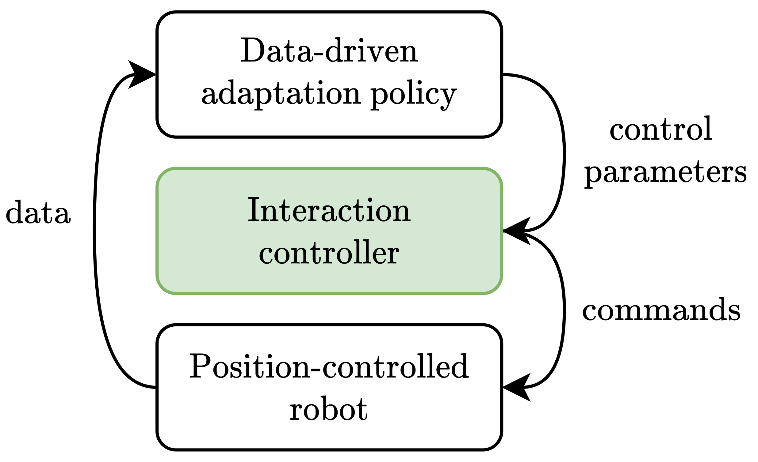
2.1. Interaction Control

Interaction control theory relies on the assumption that robots are torque-commanded, thus centralized control laws must be designed in such a way that joint positions, velocities, and accelerations are given, and torques are obtained through inverse dynamics [1,2]. However, real robots seldom allow for torque commands, rather they expose a position or velocity interface and perform joint control internally. The control strategy is often proprietary and unknown, but, in most cases, either a decentralized control, i.e., independent joint control, or an inverse dynamics control is applied, which cancels out the manipulator dynamics making it equivalent to a double-integrator system. As a consequence, it is possible to impose a desired behavior through the basic linear control theory. Robot-agnostic control schemes must be built so as to assign joint position references, taking into account the most restrictive assumptions of independent joint control: high transmission coefficients of the motors, a low armature resistance, and low joint accelerations for the task execution. If these requirements are satisfied, which is the case of most real robots, we can assume that the commanded position is reached with high precision.
It follows that, in order to build an interaction controller, we have to consider that the system to be controlled is not the mere robot but the position-controlled robot, which is already equipped with motion control.

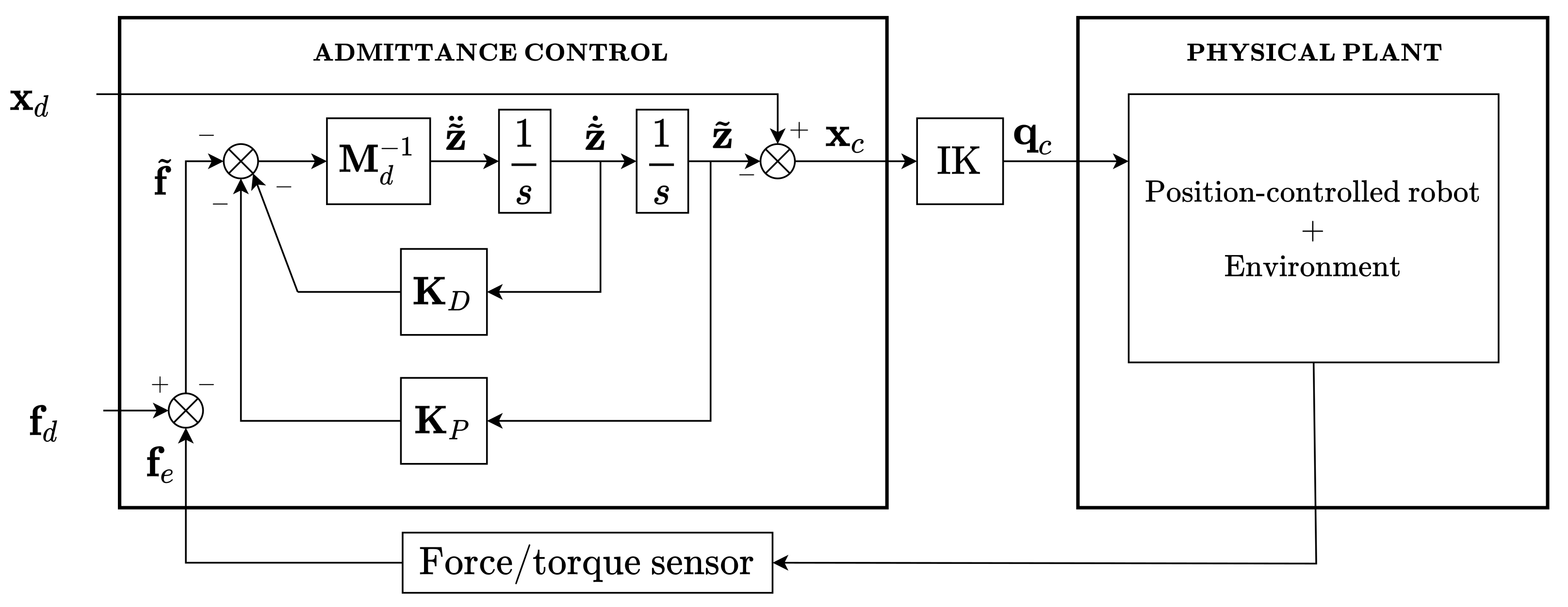
2.1.1. Admittance Control

In most interaction scenarios, the manipulator is required to have compliant behavior along specified workspace directions. Impedance control is usually adopted to achieve this goal with the idea to assign mass-spring-damper dynamics to the end-effector. In general, the impedance control scheme is designed so as to output joint accelerations, which are then used to retrieve torques through inverse dynamics. It follows that it cannot be used with position-controlled robots and admittance control is used instead. It is characterized by an inner position control loop and an outer force loop, so that interaction and motion controls are decoupled. A modified workspace position reference, computed through the impedance control law, is generated, joint positions are retrieved through inverse kinematics and then sent to the robot position controller [30].
Let us consider a desired workspace task x d R m to be executed by a robotic arm with n joints and, for the sake of simplicity, neglect the orientation in the operational space assuming it to be fixed, with no torques generated at the end-effector, so that only the forces f R 3 are taken into account. The relation, through a generalized mechanical impedance, between the vector of contact forces and the position error z ˜ R 3 is given by the equation
M d z ˜ ¨ + K D z ˜ ˙ + K P z ˜ = f ˜ ,
where the position error is computed as the difference between the desired reference and the commanded one z ˜ = x d x c , while M d , K P , K D , respectively, are the diagonal mass, stiffness, and damping matrices of appropriate dimensions, used to specify the dynamic behavior in the task space. The term f ˜ = f d f e is the force tracking error, where f d is the desired force and f e is the contact force applied by the manipulator on the environment. The latter is equal and opposite to the force measured by a force/torque sensor mounted at the robot’s end-effector.
At the steady state, (1) becomes
f ˜ = K P ( x c x d ) ,
while, making the hypothesis of elastic environment, the force applied by the manipulator can be expressed as f e = K e ( x c x e ) , where K e and x e are the stiffness and the rest position of the environment, respectively. It follows that
f ˜ = f d K e ( x c x e ) .
Obtaining x c from (3) and plugging it into (2), it can be derived that, as shown in [29,31], the force error at the steady state f ˜ s s is
f ˜ s s = K P K P + K e [ f d + K e ( x e x d ) ] .
From this equation, it can be observed that only by perfectly knowing the environment it is possible to have a zero force error, by carefully selecting K P and x d . Otherwise, when the environment is unknown, the force reference is not reached and the error is subject to the imposed compliance. If one wants to control the contact force, variable impedance schemes can be used [27,28,29,30,31].
Computing z ˜ ¨ from (1) yields:
z ˜ ¨ = M d 1 [ f ˜ K D z ˜ ˙ K P z ˜ ] .
The control scheme is represented in Figure 2. This also is the implementation adopted in [29,30].
The velocity and position displacements in the workspace, z ˜ ˙ and z ˜ , are obtained through numerical integration, while the commanded workspace positions x c are given by the difference between x d and z ˜ . Then, the related n × 1 vector of joint positions q c is computed through inverse kinematics. It is worth noting that the position control is assumed to be perfect, i.e., the commanded position x c is close to the actual position x m . In case of an independent joint control, this assumption might require the desired trajectory to be slow enough for x c x m to be verified.

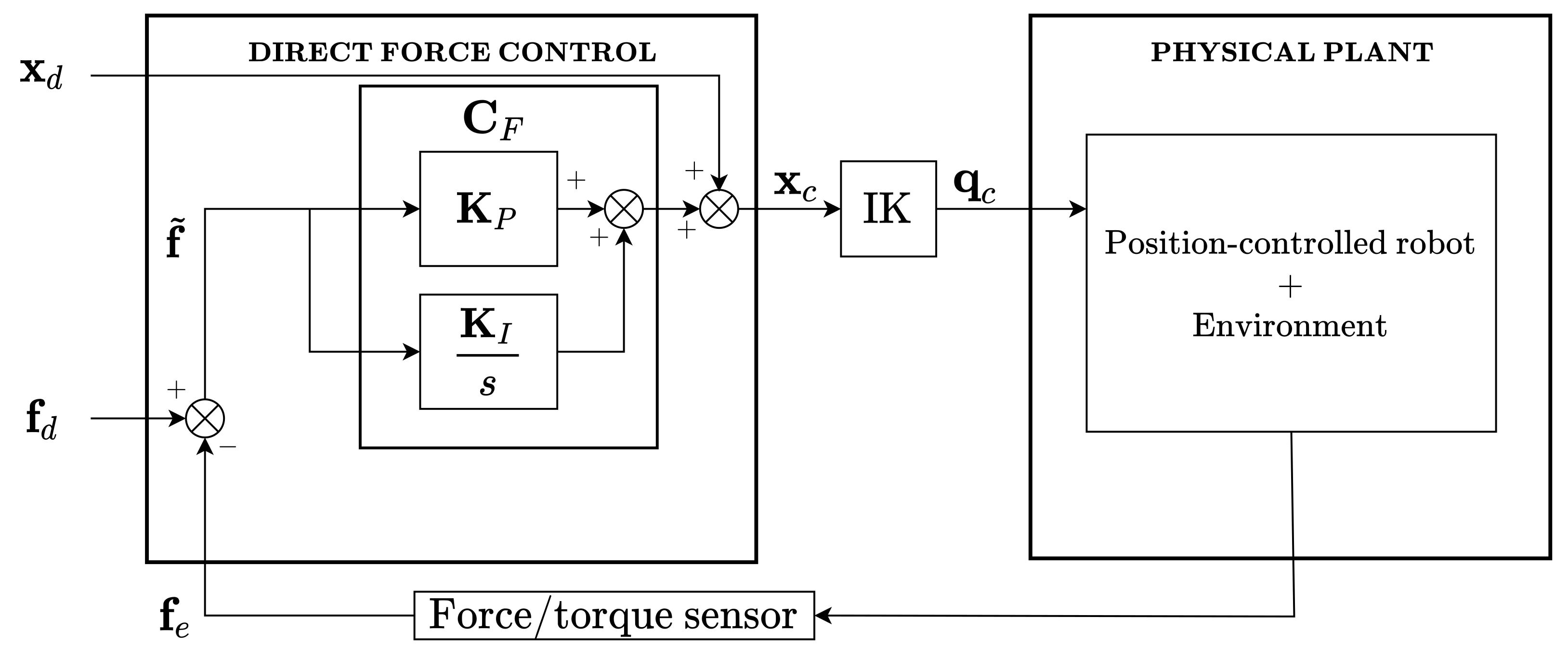
2.1.2. Direct Force Control

When an accurate control of the generated contact force is required, it is necessary to devise control schemes that allow the desired interaction force to be specified directly for one or more directions in the workspace. Hence, a direct force control scheme can be designed with the closure of an outer force regulation feedback loop generating the control input for the position-controlled robot, as shown in Figure 3.
The error between the desired force f d and actual force f e is the input of the force controller C F , which generates position commands. The difference between the actual robot position and the rest position of the environment generates a contact force via the stiffness K e , which acts as a disturbance on the position-control loop.
In order to guarantee rejection to this disturbance, a proportional-integral (PI) controller is chosen [32]:
C F = K e 1 K p + K i s ,
where K p and K i are the m × m diagonal matrices of proportional and integral gains along the m directions. The presence of the unknown environment stiffness to be compensated does not allow to make an accurate tuning of the PI. By incorporating K e 1 in PI parameters, such that K P = K e 1 K p and K I = K e 1 K i , they should be adapted as the surface changes.
If force control is not required along a direction, the corresponding elements of K p and K i are set to zero, so that the desired workspace position x d along the position-controlled directions is simply forwarded on the feed-forward chain. Joint positions are then obtained through inverse kinematics and sent to the robot.

2.2. ROS-Based Implementation

Design and implementation of the hardware-independent interaction control schemes are based on the ROS framework in order to guarantee maintainability, re-usability, modularity, and flexibility of the robotic software, as needed in the heterogeneous hyper-flexible robotic workcells. Before presenting our design, we briefly recall the main ROS functions exploited in the implementation.
The ros_control framework [22] provides an infrastructure for the robot-agnostic control, from the management of the controllers’ life-cycle and hardware resources to the libraries for the implementation of custom controllers.
The proposed architecture relies on the ROS pluginlib library [33], which allows instantiating a generic object of an abstract class and then dynamically load specific implementations at runtime, i.e., depending on the hardware architecture to be used, related functions are loaded. ros_control itself is based on a plugin architecture for basic and custom controllers. The force/torque sensor library is also implemented as a plugin so as to simplify the process of changing and mixing together different robots and sensors and to provide an extension point for new sensor drivers.
Concerning the interface towards the planning system, e.g., a reference generator, ROS supports several communication mechanisms between nodes. Among these, the actionlib-based communication [34] interface provides a client-server mechanism based on the transmission and execution of goals and exchange of feedback messages for monitoring purposes, such as the monitoring of a trajectory execution.

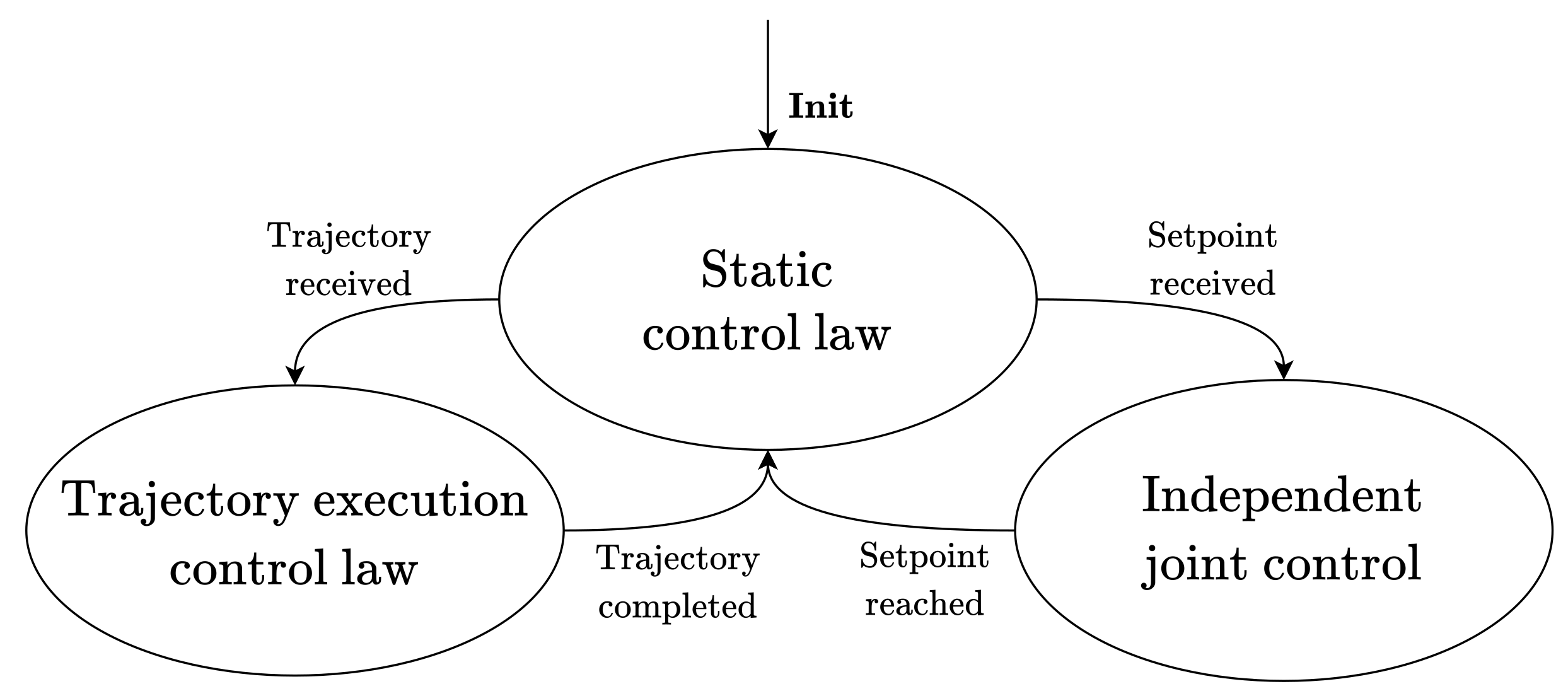
2.2.1. Finite State Machine Architecture

The two algorithms for admittance and direct force control are designed as a finite state machine (FSM), represented in Figure 4.
Assuming the robot is not in touch with the environment, the algorithm starts executing the interaction control law and, in the attempt of reaching the desired force f d , which could also be zero, moves according to the assigned dynamics.
On a practical standpoint, before the robot starts operating, it is often desirable to bring the end-effector to the task’s first configuration, with a separate command. The planning system can do this by providing a single setpoint, to be reached with absolute precision. To this purpose, pure motion control, in the form of independent joint control, is needed. In fact, if the starting point was tracked by the interaction control law, the reached point might differ from the target, due to the input force error. In addition, motion control allows commanding (and reaching) the end-effector orientation required by the task.
The FSM consists of three states and five events. The states are:
  • Static control law: the algorithm simply executes the control law, with fixed force and position references;
  • Trajectory execution control law: the algorithm still executes the control law while tracking the trajectory received as input (the tracking might not be accurate, along force-controlled directions, due to the control action);
  • Independent joint control: the interaction control law is not executed, while the independent joint control allows reaching the desired position and orientation with an assigned tolerance.
The transitions are:
  • Init: occurs when the controller is started by the controller manager [35];
  • Trajectory received: a trajectory is received;
  • Setpoint received: a setpoint is received;
  • Trajectory completed: the execution of the trajectory is completed;
  • Setpoint reached: the setpoint is reached.
It is worth specifying that, once the target point is reached, the gravity bias is removed from the force/torque sensor measures, so that null measures are delivered until the sensor gets in touch with the environment. While a setpoint is reached or a trajectory executed, no other input is allowed.

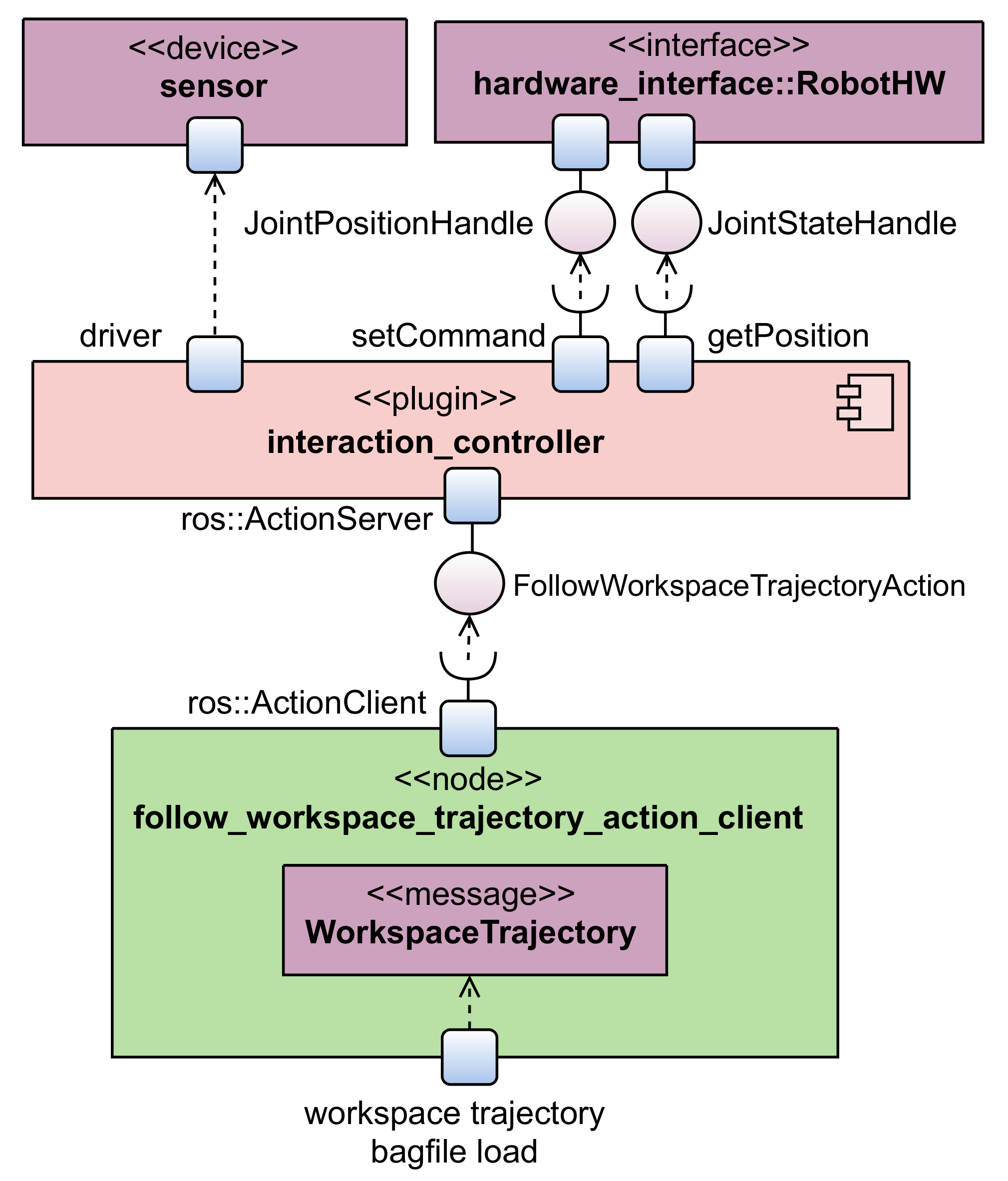
2.2.2. Action Communication Interface

Interaction controllers are ROS nodes that internally implement a communication mechanism of type ros::ActionServer. The actionlib-based communication was chosen to exploit the potential of action services so that the current state of the robot during trajectory execution can be monitored by a ros::ActionClient. A custom action message FollowWorkspaceTrajectory allows for the specification of the desired workspace trajectory together with the desired force references. The goal of this action message is the custom WorkspaceTrajectory message provided in [36] and extended to include wrench references. The feedback of the FollowWorkspaceTrajectory message will contain, for each waypoint reached by the manipulator, the desired and actual pose and wrench, and the difference between them, the error. This information is received by the ros::ActionClient, which stores it in ROS bagfiles [37] for further analyses.

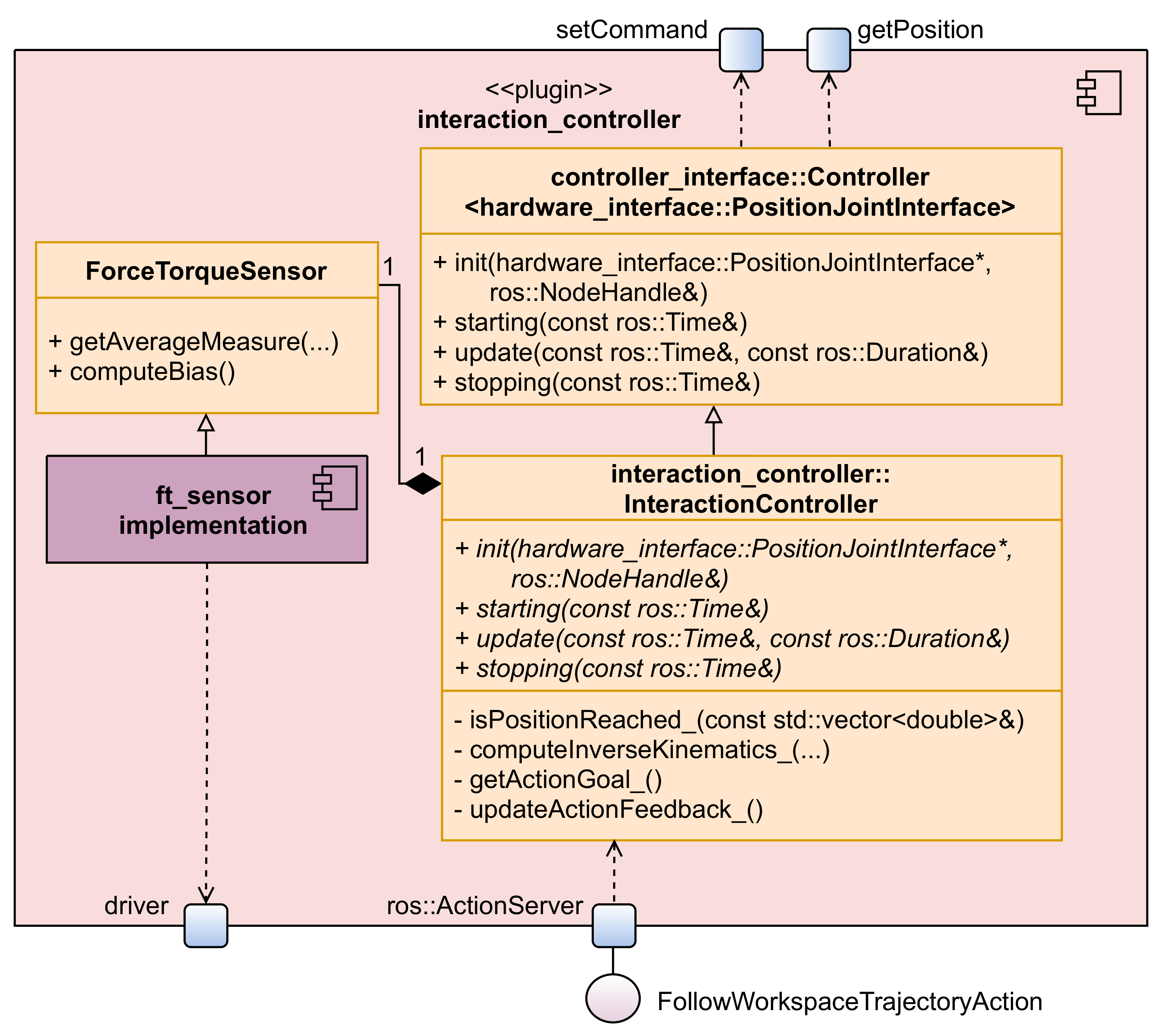
2.2.3. Implementation Details

The overall architecture is described through a context diagram and a hybrid decomposition/class diagram in Figure 5 and Figure 6, respectively. Here, the interaction_controller:: InteractionController class name is a placeholder for the real controller class name, i.e., admittance_controller::AdmittanceController or direct_force_controller::DirectForceController.
As discussed in previous sections, the real robots are position-controlled robots; thus, the interaction controllers have been implemented by inheriting the class controller_interface:: Controller h a r d w a r e _ i n t e r f a c e : : P o s i t i o n J o i n t I n t e r f a c e [38], which allows sending joint position commands and reading joint states through the provided JointHandle [39] interface.
Every controller requires the implementation of the methods init, starting, stopping, and update. While the first three functions are called when the controller is loaded, started, and stopped, respectively, update embeds the control law, i.e., the FSM described in Section 2.2.1, and is called at the control cycle frequency.
The communication between the controller and the force/torque sensor is handled through the class ForceTorqueSensor, designed as a plugin, such that specific implementations can be provided for specific sensors, both real and simulated. In particular, an object of the ForceTorqueSensor class is instantiated in the init function and is used at each update call to obtain the force measures from a driver. It is worth noting that ROS already provides a force_torque_sensor_controller [40] based on topic communication but, since the API is faster, it is preferable for real-time systems. Thus, new force/torque sensors can be added by implementing the ForceTorqueSensor interface.
One of the main issues in designing a robot-agnostic architecture is to make the software independent from the specific kinematic structure of the robot. In fact, the reference frames used for inverse kinematics and force measurements can change from robot to robot. Moreover, the Unified Robot Description Format (URDF) file used to obtain the kinematic description of the manipulator may contain additional frames that are not present in the real robot kinematic structure, as configured by the manufacturer for on-board computations, but might be implicitly used by the ROS functions. For instance, the URDF world frame is typically used for kinematic inversion, but it may not correspond to the frame in which the workspace trajectory is expressed.
The reference frames used by the interaction controllers are reported in Figure 7. F b is the base reference frame, usually used to specify the workspace trajectory. F w is the world reference frame, and, when different from F b , might be used to interpret the pose subject to inverse kinematics. F b is transformed into F w through the constant transformation matrix T b w . F m is the flange frame (usually the last frame in a kinematic chain without end-effector), and is where the force/torque sensor is mounted. F s is the sensor frame, with respect to which force/torque measures are given. The constant transformation matrix T m s depends on the mechanical interface between the flange and the sensor. F f is the end-effector frame when the robot is at the trajectory’s starting point, while F e is the end-effector-fixed moving frame.
As a consequence, controllers have been parametrized to indicate the reference frames for the task, for inverse kinematics, and for force/torque measurements, while transformations between them are automatically handled by the controller. All these frames and transformation matrices are provided by the user in configuration files and loaded on the parameter server [41]. A similar approach for the analysis of the reference frame relationships and description of the robot pose is performed in [42] for a wheel-legged robot.
In order to simplify the implementation and make it more intuitive and easy to maintain, the control laws work with references expressed in F f . Since the trajectory is commonly assigned in F b , the controller automatically handles the transformation of position references. On the contrary, force references are commonly expressed in F e ; thus, the force measurements are transformed from F s to F e . The difference between F f and F e only depends on the progress on the assigned trajectory.
The control law computes each position increment with respect to the previous point in F f . Then, the increment is expressed again in F b , added to the offset given by F f and given as input to the inverse kinematics algorithm, which will use the frame specified in the configuration files for computations. Inverse kinematics is performed by the kinematic solver configured with the robot.
Controller-specific parameters (e.g., PI gains, impedance matrices) and files containing the robot description are provided through configuration and launch files for each controller and robot and are then loaded on the parameter server. This way, if the hardware changes, only configuration files must be replaced, without the need to recompile the source code.
The developed source code is openly available in [43].

3. Results

The validation of the proposed architecture is performed on the Universal Robot’s UR10 and the Comau Smart-Six robots and their simulated version in Gazebo. Different force/torque sensors are mounted on each robot: the ATI Gamma SI-65 [44] is mounted on the UR10, the Schunk Mini 58 SI-700-30 [45] on the Smart-Six, while a simulated force/torque sensor provided by a Gazebo plugin [46] is used with the simulated robots. To handle all of these types of sensors, two implementations of the class ForceTorqueSensor are provided: ForceTorqueSensorComedi, which exploits the Comedi [47] driver for the communication with the real sensors, and ForceTorqueSensorGazebo, which collects force/torque readings through a ros::Subscriber.
The Supplementary Video S1 shows experiments performed with interaction controllers on the different robotic platforms. First, a straight line trajectory is executed while the robots interact with the environment, then some human–robot interaction scenarios are shown.

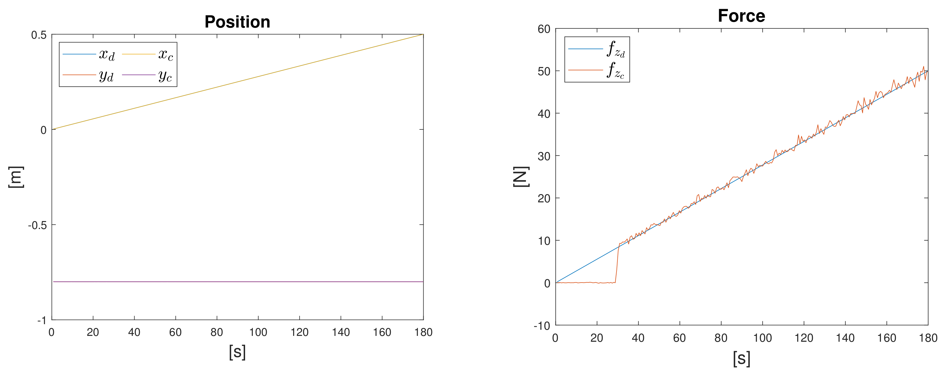
3.1. Trajectory Execution

The first experiment consists of the execution of a straight line trajectory along the horizontal direction, the x axis. While for the direct force control, the plane is placed beneath the trajectory, for admittance control, a steel ramp intersects the trajectory causing contact with the end-effector.
If the objective is to be compliant with the environment, thus to adapt to obstacles, the desired force is set to zero along the axis perpendicular to the plane, i.e., F e ’s z axis, the compliant direction.
The impedance matrices for the real UR10 are: M d = blockdiag { 0.1 , 0.1 , 0.1 } , K D = blockdiag { 300 , 300 , 500 } , K P = blockdiag { 900 , 1300 , 10 } . In order to achieve comparable performances with the simulated robot, because of the different dynamics of the manipulator and the higher stiffness of the objects in the virtual environment, the matrices are: M d = blockdiag { 1.0 , 1.0 , 0.001 } , K D = blockdiag { 900 , 900 , 5000 } , K P = blockdiag { 1300 , 1300 , 90 } . In both cases, the z component has a higher damping and a lower stiffness since the robot must be highly compliant and moderately damped in that direction, while along x and y axes, it must be stiffer, as the position must be kept with accuracy.
As it is clear from Figure 8, as soon as the robot is in contact with the ramp (around 20 s), it slides over it, causing a non-negligible position error and higher contact forces along z. Since the trajectory is longer than the ramp, when the interaction ends (around 140 s), the robot recovers the desired position and force, with zero error.
With the direct force controller, since we want to track a specific force reference, we set the desired force to a ramp from 0 to 50 N along z, which is the only force-controlled direction. PI gains for the real UR10 are: K P z = 0.8 · 10 5 and K I z = 6 · 10 5 . In the simulation, where both the robot and the environment have slightly different characteristics, the proportional gain is lower: K P z = 0.025 · 10 7 . In Figure 9, we can see that, along position-controlled directions, the position error is zero, while along the force-controlled direction, the force error is below 2 N.
The same experiments are performed with the Smart-Six by only changing configuration parameters, i.e., reference frames, impedance matrices, and PI gains in configuration files. Similar observations made for the UR10 hold, as can be seen from Figure 10, demonstrating the flexibility of the proposed architecture. It is worth noting that the controllers’ performance can be improved through better knowledge of the interaction dynamics and an informed tuning of the controllers’ parameters, but this is addressed elsewhere in the literature [31,48,49], and goes beyond the scope of this communication.

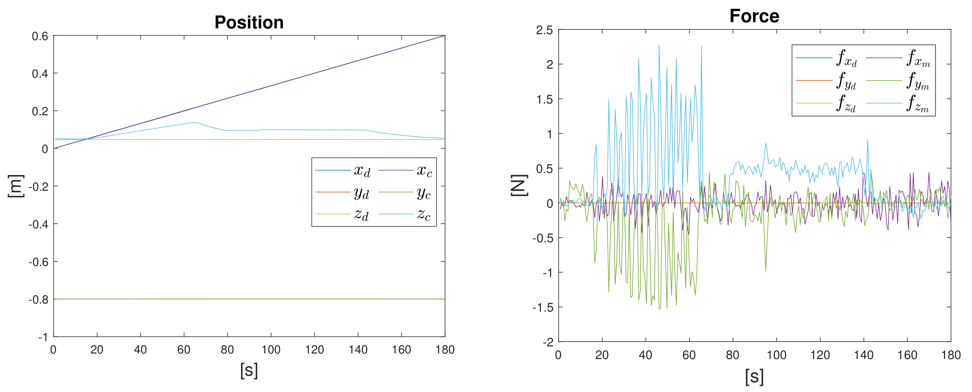
3.2. Human–Robot Interaction

Consider now the case where controllers are in the static control law state and a force is manually applied at the end-effector.
If the admittance controller is active, the robot will follow the movement of the human operator along the compliant directions, and it will oppose the movement along the stiff ones, behaving as a spring in the operational space.
If the direct force control is active and all directions are force-controlled, it is possible to set up a teaching by showing scenario by setting the desired force to zero and increasing the value of the integrative gain, e.g., up to K I = 0.01 along all directions for both robots. A human operator can bring the end-effector to specific positions in the workspace, by exerting forces on the handle tool. This way, the performed movements can be recorded, both in the workspace and joint space, and replayed autonomously.
Note that, for both controllers, when a force is exerted on intermediate links of the robot, e.g., in such a way that zero force is perceived by the force/torque sensor, the manipulator stays in its current position, as a result of the position-based motion control.

4. Conclusions

This work demonstrates how algorithms that are widely used in robotics can be made independent of the hardware architecture, such that they can be used in heterogeneous and hyperflexible robotic workcells. The challenge lies in the complexity of industrial robotic systems, making their use difficult outside of the proprietary context. We focused on the design of two new hardware-independent interaction controllers through the ROS framework, based on the action communication interface, and provided a novel API to handle any type of end-effector-mounted force/torque sensor. The developed architecture was tested on different robotic platforms as well as in simulation, demonstrating the flexibility of the proposed solution. Indeed, transferring the controllers from one robot to another is as simple as updating a few hardware-dependent configuration files, regardless of the underlying control architecture (ROS-ready, as in the case of the UR10 robot, or proprietary controller, as in the case of the Comau robot). A future extension of the framework is to enable end-effector torques management, which would cause changes in the robot orientation. This would allow considering more complex scenarios where two or more robots cooperate to accomplish a desired task. Moreover, as ros2_control becomes more mature, by keeping the control logic unchanged, the architecture proposed in this work can be easily migrated.

Supplementary Materials

The following supporting information can be downloaded at https://www.mdpi.com/article/10.3390/app12083949/s1, Video S1: Robot agnostic interaction controllers based on ROS.

Author Contributions

Conceptualization, E.F.; methodology, F.S. and E.F.; software, F.S. and E.F.; validation, F.S.; formal analysis, F.S.; investigation, F.S.; resources, P.C.; data curation, F.S. and E.F.; writing—original draft preparation, F.S.; writing—review and editing, F.S., E.F. and P.C.; visualization, F.S.; supervision, P.C.; project administration, P.C.; funding acquisition, P.C. All authors have read and agreed to the published version of the manuscript.

Funding

This research was partly funded by Italian Ministry of University and Research (MUR) grant number CUP D43D20002240006.

Institutional Review Board Statement

Not applicable.

Informed Consent Statement

Not applicable.

Data Availability Statement

The source code presented in this study is openly available on GitHub/Zenodo [43], version v0.1.1. More data are available upon request from the corresponding author.

Acknowledgments

The authors would like to thank Giovanni Longobardi for refining the controller implementation, making this work possible.

Conflicts of Interest

The authors declare no conflict of interest.

Abbreviations

The following abbreviations are used in this manuscript:
ROSrobot operating system
FSMfinite state machine
URDFunified robot description format

References

  1. Siciliano, B.; Khatib, O. Springer Handbook of Robotics; Springer International Publishing: Berlin/Heidelberg, Germany, 2016. [Google Scholar]
  2. Siciliano, B.; Sciavicco, L.; Villani, L.; Oriolo, G. Robotics. Modelling, Planning and Control; Springer: London, UK, 2009. [Google Scholar] [CrossRef]
  3. Vladareanu, L.; Lile, R.; Radulescu, M.; Mitroi, D.; Marin, D.; Ciocirlan, A.; Boscoianu, E.C.; Boscoianu, M. Intelligent control interfaces developed on Versatile Portable Intelligent Platform in order to improving autonomous navigation robots performances. Period. Eng. Nat. Sci. 2019, 7, 324–329. [Google Scholar] [CrossRef] [Green Version]
  4. Basile, F.; Caccavale, F.; Chiacchio, P.; Coppola, J.; Marino, A.; Gerbasio, D. Automated synthesis of hybrid Petri net models for robotic cells in the aircraft industry. Control Eng. Pract. 2014, 31, 35–49. [Google Scholar] [CrossRef]
  5. Basile, F.; Caccavale, F.; Chiacchio, P.; Coppola, J.; Curatella, C. Task-oriented motion planning for multi-arm robotic systems. Robot. Comput.-Integr. Manuf. 2012, 28, 569–582. [Google Scholar] [CrossRef]
  6. ROS. 2008. Available online: http://www.ros.org/ (accessed on 27 February 2022).
  7. Tavares, P.; Silva, J.; Costa, P.; Veiga, G.; Moreira, A. Flexible Work Cell Simulator Using Digital Twin Methodology for Highly Complex Systems in Industry 4.0. In Advances in Intelligent Systems and Computing; Springer: Cham, Switzerland, 2018; pp. 541–552. [Google Scholar] [CrossRef] [Green Version]
  8. ROS-Industrial. Available online: https://rosindustrial.org/ (accessed on 27 February 2022).
  9. Volpe, R.; Nesnas, I.; Estlin, T.; Mutz, D.; Petras, R.; Das, H. The CLARAty architecture for robotic autonomy. In Proceedings of the 2001 IEEE Aerospace Conference Proceedings (Cat. No. 01TH8542), Big Sky, MT, USA, 10–17 March 2001; Volume 1, p. 1. [Google Scholar] [CrossRef]
  10. OROCOS. Available online: https://orocos.org/ (accessed on 27 February 2022).
  11. YARP. Available online: https://www.yarp.it/latest/ (accessed on 27 February 2022).
  12. Lippiello, V.; Luigi, V.; Siciliano, B. An open architecture for sensory feedback control of a dual-arm industrial robotic cell. Ind. Robot. Int. J. 2007, 34, 46–53. [Google Scholar] [CrossRef]
  13. Michieletto, S.; Tosello, E.; Romanelli, F.; Ferrara, V.; Menegatti, E. ROS-I Interface for COMAU Robots. In Proceedings of the International Conference on Simulation, Modeling, and Programming for Autonomous Robots, Bergamo, Italy, 20–23 October 2014. [Google Scholar] [CrossRef]
  14. Martinez, C.; Barrero, N.; Hernandez, W.; Montaño, C.; Mondragón, I. Setup of the Yaskawa SDA10F Robot for Industrial Applications, Using ROS-Industrial. In Advances in Automation and Robotics Research in Latin America; Chang, I., Baca, J., Moreno, H.A., Carrera, I.G., Cardona, M.N., Eds.; Springer International Publishing: Berlin/Heidelberg, Germany, 2017; pp. 186–203. [Google Scholar]
  15. Gašpar, T.; Ridge, B.; Bevec, R.; Bem, M.; Kovač, I.; Ude, A.; Gosar, Ž. Rapid hardware and software reconfiguration in a robotic workcell. In Proceedings of the 18th International Conference on Advanced Robotics (ICAR), Hong Kong, China, 10–12 July 2017; pp. 229–236. [Google Scholar] [CrossRef] [Green Version]
  16. Gašpar, T.; Deniša, M.; Radanovič, P.; Ridge, B.; Rajeeth Savarimuthu, T.; Kramberger, A.; Priggemeyer, M.; Roßmann, J.; Wörgötter, F.; Ivanovska, T.; et al. Smart hardware integration with advanced robot programming technologies for efficient reconfiguration of robot workcells. Robot. Comput.-Integr. Manuf. 2020, 66, 101979. [Google Scholar] [CrossRef]
  17. Rajapaksha, U.K.; Jayawardena, C.; MacDonald, B.A. ROS Based Heterogeneous Multiple Robots Control Using High Level User Instructions. In Proceedings of the TENCON 2021—2021 IEEE Region 10 Conference (TENCON), Auckland, New Zealand, 7–10 December 2021; pp. 163–168. [Google Scholar] [CrossRef]
  18. La Mura, F.; Todeschini, G.; Giberti, H. High Performance Motion-Planner Architecture for Hardware-In-the-Loop System Based on Position-Based-Admittance-Control. Robotics 2018, 7, 8. [Google Scholar] [CrossRef] [Green Version]
  19. Fernandez, S.R.; Olabi, A.; Gibaru, O. Multi-Surface Admittance Control Approach applied on Robotic Assembly of Large-Scale parts in Aerospace Manufacturing. In Proceedings of the 2019 19th International Conference on Advanced Robotics (ICAR), Belo Horizonte, Brazil, 2–6 December 2019; pp. 688–694. [Google Scholar] [CrossRef]
  20. Xue, X.; Huang, H.; Zuo, L.; Wang, N. A Compliant Force Control Scheme for Industrial Robot Interactive Operation. Front. Neurorobot. 2022, 16. [Google Scholar] [CrossRef] [PubMed]
  21. Scherzinger, S.; Roennau, A.; Dillmann, R. Forward Dynamics Compliance Control (FDCC): A new approach to cartesian compliance for robotic manipulators. In Proceedings of the IEEE/RSJ International Conference on Intelligent Robots and Systems (IROS), Vancouver, BC, Canada, 24–28 September 2017; pp. 4568–4575. [Google Scholar] [CrossRef]
  22. Chitta, S.; Marder-Eppstein, E.; Meeussen, W.; Pradeep, V.; Rodríguez Tsouroukdissian, A.; Bohren, J.; Coleman, D.; Magyar, B.; Raiola, G.; Lüdtke, M.; et al. ros_control: A generic and simple control framework for ROS. J. Open Source Softw. 2017, 2, 456. [Google Scholar] [CrossRef]
  23. Ferrein, A.; Schiffer, S.; Kallweit, S. The ROSIN Education Concept—Fostering ROS Industrial-Related Robotics Education in Europe. In Proceedings of the ROBOT’2017: Third Iberian Robotics Conference, Seville, Spain, 22–24 November 2017. [Google Scholar] [CrossRef]
  24. ROS 2 Documentation. 2022. Available online: https://docs.ros.org/en/foxy/index.html (accessed on 27 February 2022).
  25. Mayoral-Vilches, V.; Pinzger, M.; Rass, S.; Dieber, B.; Gil-Uriarte, E. Can ROS be used securely in industry? Red teaming ROS-Industrial. arXiv 2020, arXiv:2009.08211. [Google Scholar]
  26. Gazebo. Available online: http://gazebosim.org/ (accessed on 27 February 2022).
  27. Roveda, L.; Testa, A.; Shahid, A.; Braghin, F.; Piga, D. Q-Learning-Based Model Predictive Variable Impedance Control for Physical Human-Robot Collaboration. Preprint Submitted to Elsevier. Available online: https://www.researchgate.net/publication/354569180_Q-Learning-Based_Model_Predictive_Variable_Impedance_Control_for_Physical_Human-Robot_Collaboration (accessed on 27 February 2022).
  28. Peng, G.; Chen, C.L.P.; Yang, C. Neural Networks Enhanced Optimal Admittance Control of Robot-Environment Interaction Using Reinforcement Learning. IEEE Trans. Neural Netw. Learn. Syst. 2021, 1–11. [Google Scholar] [CrossRef] [PubMed]
  29. Lee, K.; Buss, M. Force Tracking Impedance Control with Variable Target Stiffness. IFAC Proc. Vol. 2008, 41, 6751–6756. [Google Scholar] [CrossRef] [Green Version]
  30. Li, C.; Zhang, Z.; Xia, G.; Xie, X.; Zhu, Q. Efficient Force Control Learning System for Industrial Robots Based on Variable Impedance Control. Sensors 2018, 18, 2539. [Google Scholar] [CrossRef] [PubMed] [Green Version]
  31. Duan, J.; Gan, Y.; Chen, M.; Dai, X. Adaptive variable impedance control for dynamic contact force tracking in uncertain environment. Robot. Auton. Syst. 2018, 102, 54–65. [Google Scholar] [CrossRef]
  32. De Schutter, J.; Van Brussel, H. Compliant Robot Motion II. A Control Approach Based on External Control Loops. Int. J. Robot. Res. 1988, 7, 18–33. [Google Scholar] [CrossRef] [Green Version]
  33. Pluginlib. Available online: http://wiki.ros.org/pluginlib (accessed on 27 February 2022).
  34. Actionlib. Available online: http://wiki.ros.org/actionlib (accessed on 27 February 2022).
  35. Controller_manager. Available online: http://wiki.ros.org/controller_manager (accessed on 27 February 2022).
  36. Ferrentino, E.; Salvioli, F.; Chiacchio, P. Globally Optimal Redundancy Resolution with Dynamic Programming for Robot Planning: A ROS Implementation. Robotics 2021, 10, 42. [Google Scholar] [CrossRef]
  37. Rosbag. Available online: http://wiki.ros.org/rosbag (accessed on 27 February 2022).
  38. PositionJointInterface. Available online: http://docs.ros.org/melodic/api/hardware_interface/html/c++/classhardware__interface_1_1PositionJointInterface.html (accessed on 27 February 2022).
  39. JointHandle. Available online: http://docs.ros.org/en/jade/api/hardware_interface/html/c++/classhardware__interface_1_1JointHandle.html (accessed on 27 February 2022).
  40. Force_torque_sensor_controller. Available online: http://wiki.ros.org/force_torque_sensor_controller (accessed on 27 February 2022).
  41. Parameter Server. Available online: http://wiki.ros.org/ParameterServer (accessed on 27 February 2022).
  42. Niu, J.; Wang, H.; Shi, H.; Pop, N.; Li, D.; Li, S.; Wu, S. Study on structural modeling and kinematics analysis of a novel wheel-legged rescue robot. Int. J. Adv. Robot. Syst. 2018, 15, 1729881417752758. [Google Scholar] [CrossRef] [Green Version]
  43. Storiale, F.; Ferrentino, E. Robot-Agnostic Interaction Controllers Based on ROS. GitHub/Zenodo. Available online: https://zenodo.org/record/6306080#.Yhzz1OjMK3C (accessed on 27 February 2022).
  44. F/T Sensor Gamma—ATI Industrial Automation. Available online: https://www.ati-ia.com/products/ft/ft_models.aspx?id=gamma (accessed on 27 February 2022).
  45. FTN-Mini-58 SI-700-30—Schunk. Available online: https://schunk.com/tw_en/gripping-systems/product/39921-ftn-mini-58-si-700-30/ (accessed on 27 February 2022).
  46. Gazebo Ros Force/Torque Sensor Plugin. Available online: http://docs.ros.org/en/jade/api/gazebo_plugins/html/group__GazeboRosFTSensor.html (accessed on 27 February 2022).
  47. Comedi. Available online: https://www.comedi.org/ (accessed on 27 February 2022).
  48. Roveda, L.; Vicentini, F.; Pedrocchi, N.; Braghin, F.; Tosatti, L.M. Impedance shaping controller for robotic applications in interaction with compliant environments. In Proceedings of the 2014 11th International Conference on Informatics in Control, Automation and Robotics (ICINCO), Vienna, Austria, 1–3 September 2014; Volume 2, pp. 444–450. [Google Scholar] [CrossRef]
  49. Beltran-Hernandez, C.C.; Petit, D.; Ramirez-Alpizar, I.G.; Nishi, T.; Kikuchi, S.; Matsubara, T.; Harada, K. Learning Force Control for Contact-Rich Manipulation Tasks With Rigid Position-Controlled Robots. IEEE Robot. Autom. Lett. 2020, 5, 5709–5716. [Google Scholar] [CrossRef]
Figure 1. Robot-agnostic interaction control with adaptation policy.
Applsci 12 03949 g001
Figure 2. The admittance control scheme for position-controlled robots.
Applsci 12 03949 g002
Figure 3. The direct force control scheme for position-controlled robots.
Applsci 12 03949 g003
Figure 4. Finite state machine for interaction controllers implemented in ROS.
Applsci 12 03949 g004
Figure 5. Context diagram.
Applsci 12 03949 g005
Figure 6. Hybrid decomposition/class diagram.
Applsci 12 03949 g006
Figure 7. Reference frames used in the interaction controllers.
Applsci 12 03949 g007
Figure 8. Commanded end-effector positions (left) and measured end-effector forces (right) of the UR10 during the execution of the workspace trajectory with the admittance controller. Quantities are compared to the desired positions and forces.
Applsci 12 03949 g008
Figure 9. Commanded end-effector positions along the position-controlled axes (left) and end-effector forces along the force-controlled axis (right) of the UR10 during the execution of the workspace trajectory with the direct force controller. Quantities are compared to the desired positions and forces.
Applsci 12 03949 g009
Figure 10. End-effector positions (left) and forces (right) of the Smart-Six during the execution of the workspace trajectory with the admittance (up) and direct force (down) controllers. Quantities are compared to the desired positions and forces.
Applsci 12 03949 g010
Publisher’s Note: MDPI stays neutral with regard to jurisdictional claims in published maps and institutional affiliations.

