Featured Application
Potential routine laboratory and clinical use of synchrotron-based imaging.
Abstract
Synchrotron X-ray radiation (SXR) has been widely studied to explore the structure of matter. Recently, there has been an intense focus on the medical application of SXR in imaging. This review is intended to explore the latest applications of SXR in medical imaging and to shed light on the advantages and drawbacks of this modality. The article highlights the latest developments in other fields that can greatly enhance the capability and applicability of SXR. The potentials of using machine and deep learning (DL)-based methods to generate synthetic images to use in regular clinics along with the use of photon counting X-ray detectors for spectral medical imaging with SXR are also discussed.
1. Introduction
Synchrotron X-ray radiation (SXR) has a variety of features that compete with conventional X-ray imaging in the field of research with direct and indirect clinical advantages, from having a tunable monochromatic beam to an inherent coherent self-collimated X-ray beam, over a wide range of energies [1].
The process of image formation in conventional radiology depends on the absorption and transmission differentiation of the primary X-ray beam, part of the X-ray beam is absorbed while the rest is transmitted through different organs and tissues. As the body consists of different tissues with different physical properties (e.g., thickness, density, atomic number, etc.), the beam is subjected to different attenuation as it travels, and an attenuation map is formed at the detector representing an image contrast of the anatomic area of interest [2]. The unavoidable limitation of this approach is the low flux available in the standard poly-energetic X-ray imaging system, poor detection of signals passing through the soft tissue. Because of these reasons, the poor soft tissue contrast provided by the system eventually affects the pathologic diagnosis and can only be conclusive with biopsy confirmation. Furthermore, the non-useful low energy of the conventional X-ray beam needs to be filtered out for two important reasons: (1) to reduce the amount of X-ray dose to the patient and (2) to reduce the scattering effect which is a prime source of reduction in contrast and signal to noise ratio (SNR).
On the other hand, synchrotron generates very high flux of SXR. Such high flux enables the selection of a narrow energy band from a full radiation spectrum, which allows researchers to characterize the structural and functional process of many diseases (e.g., breast cancer, lung disease, etc.) [3].
The purpose of this review article is to explore the latest applications of SXR in medical imaging and to shed light on the advantages and drawbacks of this modality. The article highlights the latest developments in other fields that can greatly enhance the capability and applicability of SXR. The potentials of using machine and deep learning (DL)-based methods to generate synthetic images to use in regular clinics along with the use of energy counting X-ray detector, for the purpose of spectral medical imaging with SXR, are also discussed.
2. Overview of Synchrotron
A synchrotron primarily consists of an electron gun, linear accelerator (linac), circular shape vacuum tubes with circumferences of up to several hundred meters (booster and storage rings), beamline and end station. Once the electrons are generated by the electron gun, they go through the acceleration process in the linac to attain the speed close to the speed of light. These electrons are then transferred to the booster ring, where their energies are increased before transferring to the storage ring. A series of magnets separated by straight sections allows the electrons to circulate around the storage ring. Electromagnetic radiation (synchrotron light with broad-spectrum rays covering from microwaves to hard X-rays) is generated as a result of deflection of the electrons in the magnetic field created by the bending magnets. The intensity of the synchrotron light can be significantly increased by placing an insertion device (wiggler or undulator) in the straight sections of the ring.
When the high intensity synchrotron light exits the storage ring through a guided shielded end, it is modulated by slits, filters and different X-ray optical components called monochromator devices, silicon crystals with focusing bent elements mirrors and refraction elements. The user can select the wavelength required for experiment either with a suitable monochromator or adjusting the emission wavelength of the insertion devices. There is also a cooling system to regulate the high heat load during experiment. A simplified layout of a synchrotron to produce monochromatic X-ray radiation is shown in Figure 1.
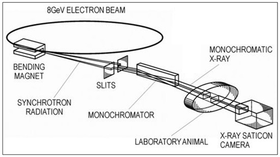
Figure 1.
A simplified layout of a synchrotron to produce monochromatic X-ray radiation. Reproduced with modification from [4].
In a synchrotron, a beam of emitting electrons with rest mass and speed is first accelerated to acquire the speed of light (). The beam is then guided, bent and focused through a series of powerful magnets to emit electromagnetic radiation. The radiation pattern is compressed into a narrow cone in the region of the X-ray spectrum but is millions of times brighter than the conventional X-ray in the direction of motion, resulting in an emission tangential to the particle orbit. This radiation is known as synchrotron X-ray radiation (SXR). An example comparison of the SXR spectrum with conventional X-ray tube radiation is shown in Figure 2.
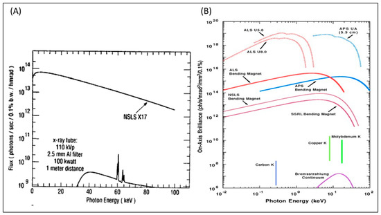
Figure 2.
(A) SXR spectrum from the X17 superconducting wiggler beam port at the National Synchrotron Light Source (NSLS) in comparison to a high-power conventional X-ray tube source. Reprinted with permission from [5]. (B) Brilliance of emitted photons (photons/sec/mrad2/mm2/0.1%) vs. energy of the emitted photon (KeV) for different sources. U in the figure refers to an undulator. Figure courtesy of Argonne National Laboratory and reprinted with permission from [6]. The range of photon energy is from UV (101 eV) up to hard X-rays (105 eV). The vertical lines at the bottom of the figure represent K emission and the bottom curve represent bremsstrahlung that is typical for all X-ray tubes that are restricted to a small range of wavelengths with low brilliance. The SXR emissions, compared to the other sources, are several orders of magnitude higher and for a broader set of frequencies (represented in logarithmic scale in both x and y axes) [7].
The opening angle is measured in milliradian (mRad) and given by the following equation [3]
In Equation (1), for electrons and positrons. For a storage ring of energy , synchrotron radiation is highly collimated with and can provide extremely high fluxes on very small areas even at a distance of tens of meters away from the storage ring.
Two types of SXR sources are used: bending magnets and insertion devices. When the bending magnet is used as a source, a very stable beam over a broad spectrum is produced. On the other hand, when the insertion device is the source (i.e., an array of magnets inserted into the straight sections of the storage ring), a more intense, tunable light is produced and optimized to specific energy (e.g., 3 GeV) [1].
Brightness or brilliance is proportional to the total emitted power , the emitting source area, and the angular divergence of the emission and can be represented by the following equation [8]:
3. Synchrotron X-ray Radiation in Medical Imaging
SXR imaging provides several advantages over conventional X-ray radiation that can be utilized in medical imaging, e.g., (i) high intensity, (ii) tunability, (iii) very good natural collimation, etc. [5,9]. The wide range of applications of SXR in medical imaging has been investigated over the years. By the mid-1980s, researchers were able to investigate human tissues, tendons, cartilages and brain, by producing synchrotron-based mammography, CT and digital subtraction angiography [5,9].
Furthermore, SXR showed to be a valuable tool for non-invasive imaging of brain cytoarchitecture at cellular resolution (i.e., imaging whole neurons), which studies neurons morphology and connectivity with a pixel size down to 0.82 μm for high resolution, which is far superior to that produced by the most advanced CT, MRI and DSA [10].
The application of SXR in medical imaging is summarized in Table 1. Some of the notable applications are discussed in more detail in the following subsections.

Table 1.
Applications of synchrotron X-ray radiation in medical imaging.
3.1. Breast Cancer
Breast cancer patients’ survival rate highly depends on its early diagnosis. Breast cancer was found to be the second most common type of cancer-based on its fatality rate. This rate is expected to drop from second to fourth, based on a projected decline in fatality rates in 2017 [31]. The main reason for this expected decline in fatalities among breast cancer sufferers is the huge investment over the years in research and development in diagnostic technologies specifically targeting breast cancer. Conventionally, traditional imaging modalities such as X-rays, magnetic resonance imaging (MRIs), and ultrasounds have been the standard diagnostic tools utilized in detecting breast cancer. These imaging technologies obtain such high resolutions that accurately localize the lesion inside the tissue. For instance, 3T MRI machines are capable of resolving details as small as 1 millimeter, and that resolution can be improved to 0.5 millimeters in a 7-T machine. Emerging optical imaging techniques such as diffuse optical imaging and photoacoustic are noninvasive medical imaging techniques capable of providing functional information of the tissue [32,33]. However, the limited spatial resolution (around 1 cm) of these techniques is a challenge that usually is tackled by optical Imaging techniques with traditional X-rays, MRI, or ultrasound modalities [34,35].
New screening techniques which improve the sensitivity and specificity of current diagnostic modalities are needed to recognize women with early stage diseases. A recent study highlighted that propagation-based phase-contrast computed tomography (PB-CT) with synchrotron radiation (Australian Synchrotron (Clayton, Melbourne, Australia)) can provide significantly better breast cancer diagnosis accuracy with a similar level of exposure to the radiation [23]. A mastectomy sample from a 60-year-old woman was used for the investigation. The CT images along with the volume-rendered image are shown in Figure 3. The relative visual grading analysis (VGASrel) of phase-contrast CT images was found to be 0.99 in this study indicating its higher quality than conventional absorption CT images.
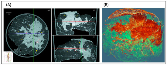
Figure 3.
CT with SXR for excised breast. (A) transaxial, coronal, and sagittal view of the excised breast and (B) 3D rendered image of the same breast. The parenchymal distortion and speculations are clearly visible along with the tumor into the skin. Reprinted with permission from [23].
For breast cancer patients, different abnormal features of hair have been identified, such as the upgrowth of lipids and medulla loss of the patient hair are all potential biomarkers for screening of breast cancer. Hair samples from breast cancer patients were collected for determining diffraction patterns and results showed a new circular feature in a specific area of 4.6 angstroms. The observed samples were then identified ad positive and negative. The positive ones had a circular feature of 1.320.02. Synchrotron X-ray diffraction experiments were performed on the small-angle X-ray scattering—wide-angle X-ray scattering (SAXS-WAXS) beamline at the Australian Synchrotron, Melbourne. A MAR165 detector was used for the alignment of the sample and also for data collection. Diffraction patterns were analyzed using FIT2D and Saxs15ID. Synchrotron X-ray sources at the Advanced Photon Source (Argonne National Laboratory) were used on two beamlines BioCAT and ChemMatCARS. The beam size was 100 μm in the horizontal direction and 50 μm in the vertical direction. Two dimensional diffraction patterns were obtained investigating three or more samples of each species on each of these beamlines. The dimension of the pixel of the image plates was 0.1 × 0.1 mm [36,37].
Another group has utilized synchrotron X-ray nanoscopic 2D/3D imaging to investigate the structural variation for hair strands of breast cancer patients during cancerous progression and healthy individuals. Theoretically, a 30% efficiency was expected from this method. The first-order focal length was 40 mm at 6.78 KeV. The field of view was typically 110 lm diameter, with a resolution of 100 nm. A thin (18 lm) LSO: TB scintillator crystal (FEE, Germany) with a 10 lm diameter and a 203-lens handmade optical microscope make up the detector. A charge-coupled device with 203 objective lenses (Zeiss) made up the microscope. Each pixel on the CCD is 4096 4096 pixels of 9 lm size. A holed aluminum-film phase plate with a diameter of 3.78 mm was used for Zernike phase contrast. Data from nanotomography were collected using the same setup as previously described. Each specimen was rotated in place on a computer-controlled precision stage with an interval of 0.5 increments through 180, 0.5 s exposure duration per projection for data collection [13]. Nanoscopic projection and CT scanning of the hair samples were accomplished by a monochromatic synchrotron X-ray at the Pohang Accelerator Laboratory. The study revealed that there is a high correlation between the medulla loss demonstrated by the structural variations of the high-resolution synchrotron X-ray and the cancerous progression (as illustrated in Figure 4). The medulla loss is also age-dependent, which imposes a challenge to the accuracy of this technique. Recently, scientists have started looking for a more compact and cheap method to the high-resolution synchrotron X-ray imaging to image the internal structure of the hair. The healthy hair samples were undergone nanoscopic projection and CT scanning using a monochromatic synchrotron X-ray (6.78 keV) at the Pohang Accelerator Laboratory (PAL) 7C beamline. Reconstruction pictures of tomography data were created by utilizing the OCTOPUS software package to apply a filtered back-projection method on the projection image [38]. Notably, in this study, the authors developed cheap near-infrared microscopy (NIRM) to achieve a comparable high spatial resolution of the monochromatic synchrotron X-ray imaging. The developed NIRM was able to detect complete medulla loss (CML) per hair strand at (60.9 ± 10.2%) (p < 0.001) in the hair of all cancer patients than in the hair of either healthy individuals (less than 3.7 ± 7.5%) or those with benign disease (30.6 ± 5.9%). The method is based on photons scattering contrast between medulla and cortex tissue of hair. The study also compared the synchrotron X-ray nanotomography images to those acquired by NIRM of the same hair samples.
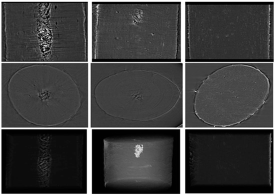
Figure 4.
Synchrotron X-ray nanoscopic images of the hair samples. In this figure, the three rows show projection (upper), axial (middle) and 3D rendering (lower) images, respectively. The medulla of a healthy hair, and the distribution of discontinuous or complete medulla loss in a cancer hair are shown in the columns from the right to left, respectively (reprinted with permission from [13]).
3.2. Coronary Angiography
One of the approaches of synchrotron radiation in the field of cardiovascular studies is SR microangiography, which is suggested to be used as a substitute for conventional angiography. SR microangiography performs high contrast imaging of microvessels in milliseconds with an enhanced image resolution and clarity compared to conventional angiography. The two approaches that vary in using SR angiography include (1) K-Edge subtraction angiography (KES) and (2) single energy temporal subtraction angiography. These two approaches vary in the case of imaging area and the way of achieving optimization of the vessel image contrast. In KES, an iodine contrast agent is used in the blood which absorbs X-rays, and an image is produced subtracting the low energy image from the high energy image created from just below and above the K-Edge energy, respectively, using narrowly separated line detectors. In the second approach of single energy temporal subtraction, images are produced using single energy of SXR just above the K-Edge. An image without contrast is first subtracted, which helps to emphasize the contrast agent contained in blood vessels. Though it is well developed, complications and mortality (0.1–0.2%) are still there. Injection of the contrast agent into a peripheral vein could help in avoiding risks associated with arterial catheterization. However, the contrast gets diluted through the heart and lung before reaching the coronary arteries. The coronary arteries of rats were visualized with a big focal spot X-ray tube that delivered enough flux and exposure periods of 100 milliseconds with a finely tuned X-ray of 33.2 keV using a monochromator which is just above the iodine K Edge energy for maximum contrast. The absorbed X-rays in the pick-up tube’s photoconductive layer are transformed immediately into electron-hole pairs, resulting in a video signal. The detector has two zoom imaging modes: (1) fields of view of mm and mm, with 1024 1024 pixels and pixel sizes of 7.0 μm and 4.5 μm, respectively; (2) the principal mode, with an input field of 9.5 9.5 mm and pixel size of 9.5 μm. A total of 22 images are captured at a rate of 30 frames per second in a digital image acquisition system with a 10-bit resolution, 1024 1024-pixel format with 30 frames per second [4].
On the other hand, an SXR-based coronary angiography with intravenous injection and the KES method can provide details that can be suitable for diagnosing coronary disease. The advantage of SXR microangiography is the ability to study the microcirculation of small animals within their physical milieu as it can visualize the coronary and pulmonary microvessels within the intact chest wall of the animals. This approach was not possible before with conventional X-ray systems. Figure 5 shows SXR-based microangiography [9].
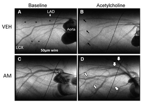
Figure 5.
SXR-based coronary angiography of rat hear. The images were acquired 72 h after ischemia-reperfusion injury. (A,C) represent single-frame images of iodine contrast during baseline condition and (B,D) during acetylcholine infusion. Reprinted with permission from [4].
Another application of SXR in coronary angiography is transvenous angiography. In this method, chronography of iodine is used in which K-edge of iodine is enclosed by two monochromatic X-ray beams. The final image is produced by the logarithmic subtraction of the images created by the beams. The advantages of this method are that the signals arising from attenuation of iodine are enhanced and the signals arising from attenuation of soft tissue and bone are suppressed. The X-ray dose used during SXR angiography is comparatively less than conventional angiography and requires significantly less patient exposure. It is assumed that with additional experience, fewer frames will be needed to be recorded during transvenous angiography [39]. The electron beam which is used in the experiment for transvenous coronary angiography has a 3.0 GeV energy and a 40–80 mA current. The beamline IV-2, which was used in these tests, is lit by an 18 kg wiggler with eight poles (1 gauss = 1 × 10⁻⁴ Tesla). The transmitted X-rays impinge on the 300 sensitive elements of a Si (Li) linear detector after passing through the subject. The center-to-center spacing of detector components is 0.5 mm, and the beams’ height is 0.5 mm, hence the system’s pixel resolution is 0.5 mm × 0.5 mm.
3.3. Imaging Lung Ventilation
A recent study demonstrated that dual-energy KES CT imaging with SXR is capable of generating morphological and regional ventilation images along with quantitative regional maps of deposition of iodine-containing aerosol particles (after 5 and 10 minutes of aerosol administration) [22]. Acquisition of lung morphology, regional ventilation along with the quantitative information of regional aerosol particle deposition using single modality was never achieved before. The study was carried out on six rabbits with normal lung (n = 6) and six rabbits with asthma model (methacholine (MCH)-induced bronchoconstriction). The images are shown in Figure 6.
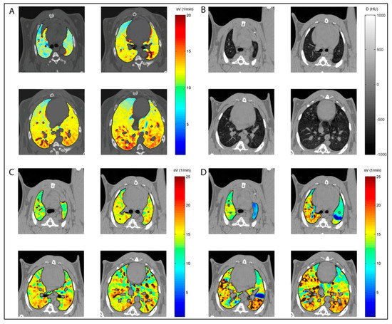
Figure 6.
Dual-energy KES CT imaging with SXR. (A) Control rabbit, (B) lung morphology, (C) animal with methacholine (MCH)-induced bronchoconstriction at baseline and (D) animal with methacholine (MCH)-induced bronchoconstriction at baseline during the challenge. Reprinted with permission from [22].
3.4. Bone and Joint Imaging
SXR has been used in bone research to analyze bone aging, disease, and factors that affect bone fragility and resistance. SXR micro CT is considered powerful as it features both biological mechanisms and control of bone quality. It can quantify thousands of lacunar volumes in 3D, which is followed by quantification and visualization for controlling matrix mineralization. All of these result in a change in bone quality and toughness. SR micro CT has shown effective results in the following bone-related studies.
3.4.1. Microstructural Features
Bone cells osteocytes, connected with one another and with the vascular network with the dendritic process, are studied using SXR micro CT. The parameters investigated in these studies are vTMD of bone and lacunar volume, density, and orientation [14]. The mechanical characteristic of the bone metal implant interface has been investigated using SXR. When compared to lab X-ray sources, synchrotron radiation with a high flux photon beam allows for higher resolution and faster imaging times. Shorter exposure times are particularly appealing for in situ loading investigations that require multiple repeated scans because they reduce the total duration of the test. This reduces the amount of drying of the test specimen (maintaining mechanical qualities) and sample relaxation during each scan (thus enabling tests that are more comparable to standard tests)
With a 3.6 m isotropic voxel size, samples were subjected to in situ pullout utilizing high-resolution synchrotron X-ray tomography at the Tomcat beamline (SLS, PSI, Switzerland) at 30 keV with a 25 ms exposure duration, resulting in a total acquisition period of 45 s per scan. Screws were pushed out at 0.05 mm increments using a custom-made loading mechanism positioned inside the beamline, acquiring several images until the sample ruptured. The field of view (FOV) of the detector was 2.8 × 7.2 mm2 (height × width) [40].
3.4.2. Crack Propagation
The 3D images found from synchrotron radiation micro CT show the size and distribution of Haversian canals, which are significantly higher in aged bones. Different bone diseases affect crack deflection and toughness. SXR micro CT, in combination with other methods, is used to analyze the mechanism of toughness. Crack-tip stress field determined at the center of a 12 mm-thick CT test piece by synchrotron X-ray diffraction at KI,max (13.2 MPa√ m) for an ultrafine-grained (<1 µm) AA5091 AI alloy. A 25 × 25 µm gauge cross-section was used [41].
3.4.3. Mineralization
In an analysis of the SR micro CT bone research data, a shift in the peak of vTMD is considered a change in mineralization. The mineralization parameters provide effective information about the disease and genetic modification of the bone matrix. SRnCT is a strong technology for 3D visualization of bone ultrastructure, with an exceptional resolution of 30 to 100 nm. However, the FOV, and thus the sample size, are reduced. For example, a 0.15 × 0.15 mm2 area FOV is implied by an SRnCT scan, equating to a 0.15 mm (height) 0.15 mm (diameter) cylindrical volume. Synchrotron light sources commonly attain resolutions of 30 nm to 0.5 m using visible light optics or X-ray optics such as zone plates and compound reflective lenses. [15].
3.4.4. Incudostapedial Joint
Synchrotron-radiation phase-contrast imaging (SR-PCI) was used in visualizing the ultrastructure of the incudostapedial joint (ISJ) of the middle ear at submicron voxel size. For each sample, a total of 900 projections spanning 180° of rotation were acquired, covering a total 3.6 mm × 2.4 mm field of view throughout the sample. Total scan time per sample was 2 h with exposure times ranging from 400 to 600 milliseconds per frame and four-frame averaging for a projection using X-ray energy of 30 keV. Each sample was placed 0.16 m away from the detector and the source-to-sample distance was 55 m [14]. In this study, ISJs of three human cadaveric were dissected and scanned using SR-PCI at 0.9 µm isotropic voxel size and compared with previous images at 9 µm voxel size. The study demonstrated that the contrast to noise ratio of bone to soft tissue for 0.9 µm was higher than the 9 µm scan indicating better discernibility of bone from soft tissue (Figure 7).
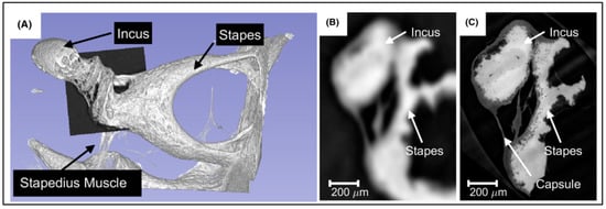
Figure 7.
(A) 3D rendered volume of the incus and stapes from the 9 µm scan. Axial slice through the ISJ at 9 µm scan (B) and 0.9 µm scan (C). The 0.9 µm clearly demonstrates high contrast between the bone and the surrounding soft tissue. Reprinted with permission from [14].
3.5. Organ to Cellular Scale Imaging
A hierarchical phase-contrast tomography (HiP-CT) has recently been proposed. The technique is based on the X-ray phase propagation and carried out using the European Synchrotron Radiation Facility (ESRF)’s Extremely Brilliant Source (EBS) [42]. HiP-CT made it possible to image the excised intact human organ (brain, lung, heart, kidney, and spleen) from organ to the cellular scale with a minimum of 1.3 μm voxel size (Figure 8).
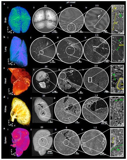
Figure 8.
Hip-CT images of (a) brain, (b) lung and (c) heart at voxel size 25 µm (column ii), 6 µm (column iii) and 2.5 µm (column iv), respectively. (d) Kidney and (e) spleen images at voxel size 25 µm (column ii), 6 µm (column iii) and 1.3 µm (column iv), respectively. Reprinted with permission from [42].
4. Future Direction
Two things can help further to realize the full potential of SXR imaging: (i) photon-counting detector (PCD) and (ii) deep learning (DL).
4.1. Photon-Counting Detector (PCD)
The potential of SXR imaging can further be realized by utilizing photon-counting detectors (PCD) in place of energy integrating detectors (EID). EIDs integrate the whole electrical current generated by the radiation sensor and ignore the charge amplitude of each individual photon detection events. The charge amplitude of each photon is proportional to the energy of the detected photon. During this integration, the summation and measurement of detector leakage current and charges produced by X-ray detection led to no information about the energy of each photon [43].
The chemical structure, mass density of the object, and the energy of the X-ray photons are factors that affect the X-ray linear attenuation coefficients. As a result, the transmitted X-ray spectra transfer information about different tissue. However, the EIDs measure the energy-integrated signals of X-ray photons, consequently losing all of the energy-dependent information. Moreover, EIDs add electronic, swank noise, and weight lower energy photons less, which leads to larger contrast between tissues than higher energy photons, thus increasing noise and decrease contrast [44].
On the other hand, when X-ray photons hit the PCD which is composed of semiconductor material with two electrodes (cathode and anode) and application-specific integrated circuits (ASICs), the photons will convert to the electrical charges directly. PCD can count the number of photons above a specified energy level. The charge produced is proportional to the incident energy of the X-ray photons. To remove electronic noise (including Fano noise), which can be interpreted by a PCD as a photon with energy located at the lower end of a typical X-ray spectrum, several energy thresholds can be set. Each detected photon is assigned to one of the energy windows determined by the threshold [45].
The energy counting capabilities of PCDs are widely used in nuclear medicine. However, in X-ray-based imaging, the use is limited due to its incapability to record a higher number of photons [46,47]. With the potential clinical benefits, higher atomic number detector materials and high-spatial-resolution fast ASICs are being developed. Cadmium telluride (CTd), or cadmium zinc telluride (CZT), is the most commonly used semiconductor for PCD along with silicon (Si) and gallium arsenide (GaAs) [48,49,50].
Since, SXR can provide monochromatic X-rays, using suitable PCDs, the scatter information within the object could be estimated, as in the case of nuclear medicine and can be utilized to increase the soft-tissue contrast and spatial resolution of the image [51,52]. However, this will require the development of ultrafast ASICs (nanosecond peaking time) along with the detector materials as the incoming SXR flux is several magnitudes higher than that of a conventional X-ray source. This is also to be noted that because of the small pixel pitches of the PCDs, inter-crystal scattering during photon detection process reduces spatial resolution. For SXR-based application using PCD, the actual impact on image blurring arising from this phenomenon is yet to be investigated.
4.2. Deep Learning (DL) for SXR Imaging
Most of the investigations using SXR are mainly carried out for in vitro and animal models or on the excised human organs at the research level. Though SXR promises to provide images with higher soft-tissue contrast and spatial resolution compared to the conventional X-ray, the main limitations to be used in routine laboratory and clinical uses are the establishment cost both in terms of land area, instrumentation, and maintenance.
In radiotherapy, the complementary information provided by two different imaging modalities (e.g., electron density by provided CT, higher soft-tissue contrast by MRI, and higher sensitivity and specificity by PET) has been exploited to carry out precise treatment planning [53,54,55,56]. In this approach, images from two different modalities are first registered in a deformable manner followed by generation of target volume and dose map.
With the current advancement of Deep Learning, it is now possible to generate synthetic images of one modality provided that the images of other modalities of the patient are available (e.g., from CT to MRI or MRI to CT) with higher precision and accuracy with peak signal-to-noise ratio of 29.38 ± 1.75 and structural similarity matric index of 0.98 ± 0.01 [57]. It has also been reported that it is feasible to generate accurate synthetic images for MRI with higher strength magnets (e.g., 7T) if the lower strength magnet MRI (e.g., 3T) images are available [58].
The most common DL architecture is U-net. The network first downsamples the original images of one modality (encoder), generate the synthetic images of another modality at down sample level, and then upsample it back to the original image space (decoder). Once the network is trained on a large dataset to calculate the optimized parameter, it can be used to any data set of the same modality on which it has been trained to provide the image of the other modality. Different U-net architectures have been used to synthesize images from CT to MRI [59] and MRI to CT [57]. Example of a U-net architecture to generate CT images from MRI image is shown in Figure 9.
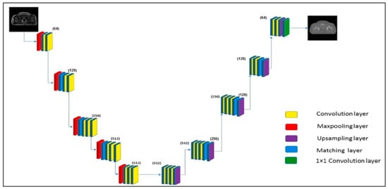
Figure 9.
MRI image to synthetic CT using U-net. It consists of a contracting path or downsample (left side) and an expansive path or upsample (right side) with 3 × 3 unpadded convolutions followed by a rectified linear unit (ReLU) and a 2 × 2 max pooling operation with stride of 2 for downsampling. Reprinted with permission from [57].
Example synthetic CT images from a T2-weighted MRI in comparison to the original CT images generated using residual learning-based u-shaped deep neural network (RUN) are shown in Figure 10 [60].
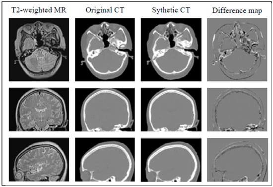
Figure 10.
Example synthetic CT images from T2-weighted MRI in comparison to the original CT images. Reprinted with permission from [60].
In the future, such advancement in synthetic image generation between different modalities can be utilized to generate SXR images, provided that the X-ray-based images of the object are available using deep learning. This approach will make it feasible to have high-quality SXR images at routine laboratory or clinical practice.
5. Summary
Synchrotron X-ray radiation source provides many useful features (e.g., high intensity and collimation, a wide range of energy spectrum, option to use monochromator to select narrow beam of the desired energy, etc.). However, because of its high cost, it has still found limited applications in routine clinical and laboratory uses. With the advancement in other disciplines, specifically, the advancement in generating synthetic images from one modality to another modality using deep learning could be adapted to generate SXR images provided that a conventional X-ray image of the object is available. A photon-counting detector (PCD) can further improve the signal-to-noise ratio and soft tissue contrast by detecting scattered photons while using the monochromatic energy provided by the SXR. A combination of the computational advancement of different disciplines with the physical capabilities of the SXR can make high-resolution SXR-based medical imaging affordable and cost-effective, especially for in vivo microstructure and cellular level studies.
Author Contributions
Conceptualization, M.T. and M.A.-H.; methodology, M.T, M.A., A.-H.A., S.T.D., K.T.S. and M.A.-H.; writing—original draft preparation, M.T., M.A., S.T.D., K.T.S. and M.A.-H.; writing—review and editing, M.T., M.A., A.-H.A., S.T.D., K.T.S. and M.A.-H.; supervision, M.T.; project administration, M.T.; funding acquisition, M.T. All authors have read and agreed to the published version of the manuscript.
Funding
The authors extend his appreciation to the Deputyship for Research & Innovation, Ministry of Education, Saudi Arabia for funding this research work.
Institutional Review Board Statement
Not applicable.
Informed Consent Statement
Not applicable.
Data Availability Statement
Not applicable.
Conflicts of Interest
The authors declare no conflict of interest.
References
- Mobilio, S.; Federico, B.F.; Meneghini, C. Synchrotron Radiation; Springer: Berlin/Heidelberg, Germany, 2015. [Google Scholar]
- Ando, M.; Uyama, C. Medical Applications of Synchrotron Radiation; Springer: Berlin/Heidelberg, Germany, 1998. [Google Scholar]
- Bayat, S.; Porra, L.; Suortti, P.; Thomlinson, W. Functional lung imaging with synchrotron radiation: Methods and preclinical applications. Phys. Med. PM Int. J. Devoted Appl. Phys. Med. Biol. Off. J. Ital. Assoc. Biomed. Phys. 2020, 79, 22–35. [Google Scholar] [CrossRef] [PubMed]
- Shirai, M.; Schwenke, D.O.; Tsuchimochi, H.; Umetani, K.; Yagi, N.; Pearson, J.T. Synchrotron radiation imaging for advancing our understanding of cardiovascular function. Circ. Res. 2013, 112, 209–221. [Google Scholar] [CrossRef] [PubMed]
- Thomlinson, W. Medical applications of synchrotron radiation. Nucl. Instrum. Methods Phys. Res. Sect. A Accel. Spectrometers Detect. Assoc. Equip. 1992, 319, 295–304. [Google Scholar] [CrossRef][Green Version]
- Helliwell, J.R. Synchrotron radiation facilities. Nat. Struct. Biol. 1998, 5, 614–617. [Google Scholar] [CrossRef] [PubMed]
- Nalin, G. Synchrotron Radiation and Synchrotron Light Sources. Available online: https://www.nottingham.ac.uk/aspire-itn/aspire-blog/aspire-blogs-2020/synchrotron-radiation-and-synchrotron-light-sources.aspx (accessed on 6 November 2021).
- Margaritondo, G.; Meuli, R. Synchrotron radiation in radiology: Novel X-ray sources. Eur. Radiol. 2003, 13, 2633–2641. [Google Scholar] [CrossRef] [PubMed]
- Suortti, P.; Thomlinson, W. Medical applications of synchrotron radiation. Phys. Med. Biol. 2003, 48, R1-35. [Google Scholar] [CrossRef]
- Fonseca, M.C.; Araujo, B.H.S.; Dias, C.S.B.; Archilha, N.L.; Neto, D.P.A.; Cavalheiro, E.; Westfahl, H., Jr.; da Silva, A.J.R.; Franchini, K.G. High-resolution synchrotron-based X-ray microtomography as a tool to unveil the three-dimensional neuronal architecture of the brain. Sci. Rep. 2018, 8, 12074. [Google Scholar] [CrossRef]
- Chen, W.; Liu, R.; Tao, S.; Shen, W.; Zhou, W.; Song, C.; Lu, H.; Xing, C. Ultrastructural Analysis of Human Gallstones using Synchrotron Radiation microCT. Comb. Chem. High Throughput Screen. 2019, 22, 13–17. [Google Scholar] [CrossRef]
- Tang, L.; Li, G.; Sun, Y.S.; Li, J.; Zhang, X.P. Synchrotron-radiation phase-contrast imaging of human stomach and gastric cancer: In vitro studies. J. Synchrotron Radiat. 2012, 19, 319–322. [Google Scholar] [CrossRef]
- Han, S.M.; Chikawa, J.; Jeon, J.K.; Hwang, M.Y.; Lim, J.; Jeong, Y.J.; Park, S.H.; Kim, H.T.; Jheon, S.; Kim, J.K. Synchrotron nanoscopy imaging study of scalp hair in breast cancer patients and healthy individuals: Difference in medulla loss and cortical membrane enhancements. Microsc. Res. Tech. 2016, 79, 23–30. [Google Scholar] [CrossRef]
- Rohani, S.A.; Allen, D.; Gare, B.; Zhu, N.; Agrawal, S.; Ladak, H. High-resolution imaging of the human incudostapedial joint using synchrotron-radiation phase-contrast imaging. J. Microsc. 2020, 277, 61–70. [Google Scholar] [CrossRef] [PubMed]
- Obata, Y.; Bale, H.A.; Barnard, H.S.; Parkinson, D.Y.; Alliston, T.; Acevedo, C. Quantitative and qualitative bone imaging: A review of synchrotron radiation microtomography analysis in bone research. J. Mech. Behav. Biomed. Mater. 2020, 110, 103887. [Google Scholar] [CrossRef] [PubMed]
- Shinohara, G.; Morita, K.; Hoshino, M.; Ko, Y.; Tsukube, T.; Kaneko, Y.; Morishita, H.; Oshima, Y.; Matsuhisa, H.; Iwaki, R.; et al. Three Dimensional Visualization of Human Cardiac Conduction Tissue in Whole Heart Specimens by High-Resolution Phase-Contrast CT Imaging Using Synchrotron Radiation. World J. Pediatric Congenit. Heart Surg. 2016, 7, 700–705. [Google Scholar] [CrossRef] [PubMed]
- Turyanskaya, A.; Rauwolf, M.; Pichler, V.; Simon, R.; Burghammer, M.; Fox, O.J.L.; Sawhney, K.; Hofstaetter, J.G.; Roschger, A.; Roschger, P.; et al. Detection and imaging of gadolinium accumulation in human bone tissue by micro- and submicro-XRF. Sci. Rep. 2020, 10, 6301. [Google Scholar] [CrossRef]
- Pascolo, L.; Gianoncelli, A.; Kaulich, B.; Rizzardi, C.; Schneider, M.; Bottin, C.; Polentarutti, M.; Kiskinova, M.; Longoni, A.; Melato, M. Synchrotron soft X-ray imaging and fluorescence microscopy reveal novel features of asbestos body morphology and composition in human lung tissues. Part. Fibre Toxicol. 2011, 8, 7. [Google Scholar] [CrossRef]
- Szczerbowska-Boruchowska, M.; Dumas, P.; Kastyak, M.Z.; Chwiej, J.; Lankosz, M.; Adamek, D.; Krygowska-Wajs, A. Biomolecular investigation of human substantia nigra in Parkinson’s disease by synchrotron radiation Fourier transform infrared microspectroscopy. Arch. Biochem. Biophys. 2007, 459, 241–248. [Google Scholar] [CrossRef]
- Honkanen, M.K.M.; Saukko, A.E.A.; Turunen, M.J.; Shaikh, R.; Prakash, M.; Lovric, G.; Joukainen, A.; Kroger, H.; Grinstaff, M.W.; Toyras, J. Synchrotron MicroCT Reveals the Potential of the Dual Contrast Technique for Quantitative Assessment of Human Articular Cartilage Composition. J. Orthop. Res. Off. Publ. Orthop. Res. Soc. 2020, 38, 563–573. [Google Scholar] [CrossRef]
- PeÃlka, J.B. Synchrotron Radiation in Biology and Medicine. Acta Phys. Pol. A 2022, 141, 3–34. [Google Scholar] [CrossRef]
- Porra, L.; Degrugilliers, L.; Broche, L.; Albu, G.; Strengell, S.; Suhonen, H.; Fodor, G.H.; Petak, F.; Suortti, P.; Habre, W.; et al. Quantitative Imaging of Regional Aerosol Deposition, Lung Ventilation and Morphology by Synchrotron Radiation CT. Sci. Rep. 2018, 8, 3519. [Google Scholar] [CrossRef]
- Pacile, S.; Baran, P.; Dullin, C.; Dimmock, M.; Lockie, D.; Missbach-Guntner, J.; Quiney, H.; McCormack, M.; Mayo, S.; Thompson, D.; et al. Advantages of breast cancer visualization and characterization using synchrotron radiation phase-contrast tomography. J. Synchrotron Radiat. 2018, 25, 1460–1466. [Google Scholar] [CrossRef]
- Peleg Walg, Y.; Krutman, Y.; Berman, A.; Orion, I. Synchrotron X-ray Irradiation of a Rat’s Head Model: Monte Carlo Study of Chromatic Gel Dosimetry. Appl. Sci. 2021, 11, 7389. [Google Scholar] [CrossRef]
- Bouchet, A.; Potez, M.; Coquery, N.; Rome, C.; Lemasson, B.; Brauer-Krisch, E.; Remy, C.; Laissue, J.; Barbier, E.L.; Djonov, V.; et al. Permeability of Brain Tumor Vessels Induced by Uniform or Spatially Microfractionated Synchrotron Radiation Therapies. Int. J. Radiat. Oncol. Biol. Phys. 2017, 98, 1174–1182. [Google Scholar] [CrossRef] [PubMed]
- Fedon, C.; Rigon, L.; Arfelli, F.; Dreossi, D.; Quai, E.; Tonutti, M.; Tromba, G.; Cova, M.A.; Longo, R. Dose and diagnostic performance comparison between phase-contrast mammography with synchrotron radiation and digital mammography: A clinical study report. J. Med. Imaging 2018, 5, 013503. [Google Scholar] [CrossRef]
- Brombal, L.; Golosio, B.; Arfelli, F.; Bonazza, D.; Contillo, A.; Delogu, P.; Donato, S.; Mettivier, G.; Oliva, P.; Rigon, L.; et al. Monochromatic breast computed tomography with synchrotron radiation: Phase-contrast and phase-retrieved image comparison and full-volume reconstruction. J. Med. Imaging 2019, 6, 031402. [Google Scholar] [CrossRef]
- Cole, J.M.; Wood, J.C.; Lopes, N.C.; Poder, K.; Abel, R.L.; Alatabi, S.; Bryant, J.S.; Jin, A.; Kneip, S.; Mecseki, K.; et al. Laser-wakefield accelerators as hard x-ray sources for 3D medical imaging of human bone. Sci. Rep. 2015, 5, 13244. [Google Scholar] [CrossRef]
- Bliznakova, K.; Russo, P.; Kamarianakis, Z.; Mettivier, G.; Requardt, H.; Bravin, A.; Buliev, I. In-line phase-contrast breast tomosynthesis: A phantom feasibility study at a synchrotron radiation facility. Phys. Med. Biol. 2016, 61, 6243–6263. [Google Scholar] [CrossRef]
- Kawata, Y.; Niki, N.; Umetani, K.; Nakano, Y.; Ohamatsu, H.; Moriyama, N.; Itoh, H. Stochastic Tracking of Small Pulmonary Vessels in Human Lung Alveolar Walls Using Synchrotron Radiation Micro CT Images; SPIE: Bellingham, WA, USA, 2013; Volume 8672. [Google Scholar]
- Society, T.A.C. Cancer Facts and Statistics. Available online: https://www.cancer.org/research/cancer-facts-statistics (accessed on 8 November 2021).
- Xu, C.; Vavadi, H.; Merkulov, A.; Li, H.; Erfanzadeh, M.; Mostafa, A.; Gong, Y.; Salehi, H.; Tannenbaum, S.; Zhu, Q. Ultrasound-Guided Diffuse Optical Tomography for Predicting and Monitoring Neoadjuvant Chemotherapy of Breast Cancers: Recent Progress. Ultrason. Imaging 2016, 38, 5–18. [Google Scholar] [CrossRef]
- Brooksby, B.; Pogue, B.W.; Jiang, S.; Dehghani, H.; Srinivasan, S.; Kogel, C.; Tosteson, T.D.; Weaver, J.; Poplack, S.P.; Paulsen, K.D. Imaging breast adipose and fibroglandular tissue molecular signatures by using hybrid MRI-guided near-infrared spectral tomography. Proc. Natl. Acad. Sci. USA 2006, 103, 8828–8833. [Google Scholar] [CrossRef]
- Althobaiti, M.; Vavadi, H.; Zhu, Q. Diffuse optical tomography reconstruction method using ultrasound images as prior for regularization matrix. J. Biomed. Opt. 2017, 22, 26002. [Google Scholar] [CrossRef]
- Fang, Q.; Selb, J.; Carp, S.A.; Boverman, G.; Miller, E.L.; Brooks, D.H.; Moore, R.H.; Kopans, D.B.; Boas, D.A. Combined optical and X-ray tomosynthesis breast imaging. Radiology 2011, 258, 89–97. [Google Scholar] [CrossRef]
- James, V. The Molecular Architecture for the Intermediate Filaments of Hard alpha-Keratin based on the Superlattice Data Obtained from a Study of Mammals Using Synchrotron Fibre Diffraction. Biochem. Res. Int. 2011, 2011, 198325. [Google Scholar] [CrossRef]
- Mistry, D.A.; Haklani, J.; French, P.W. Identification of breast cancer-associated lipids in scalp hair. Breast Cancer Basic Clin. Res. 2012, 6, 113–123. [Google Scholar] [CrossRef]
- Choi, Y.; Jeong, Y.J.; Jeon, J.G.; Park, S.H.; Choi, H.R.; Kim, J.K. Medulla loss of scalp hair in breast cancer patients determined by near-infrared microscopy. J. Biomed. Opt. 2019, 24, 1–9. [Google Scholar] [CrossRef]
- Rubenstein, E.; Hofstadter, R.; Zeman, H.D.; Thompson, A.C.; Otis, J.N.; Brown, G.S.; Giacomini, J.C.; Gordon, H.J.; Kernoff, R.S.; Harrison, D.C. Transvenous coronary angiography in humans using synchrotron radiation. Proc. Natl. Acad. Sci. USA 1986, 83, 9724–9728. [Google Scholar] [CrossRef]
- Le Cann, S.; Tudisco, E.; Turunen, M.J.; Patera, A.; Mokso, R.; Tägil, M.; Belfrage, O.; Hall, S.A.; Isaksson, H. Investigating the Mechanical Characteristics of Bone-Metal Implant Interface Using in situ Synchrotron Tomographic Imaging. Front. Bioeng. Biotechnol. 2019, 6, 208. [Google Scholar] [CrossRef]
- Withers, P.J. Fracture mechanics by three-dimensional crack-tip synchrotron X-ray microscopy. Philos. Transactions. Ser. A Math. Phys. Eng. Sci. 2015, 373, 20130157. [Google Scholar] [CrossRef]
- Walsh, C.L.; Tafforeau, P.; Wagner, W.L.; Jafree, D.J.; Bellier, A.; Werlein, C.; Kuhnel, M.P.; Boller, E.; Walker-Samuel, S.; Robertus, J.L.; et al. Imaging intact human organs with local resolution of cellular structures using hierarchical phase-contrast tomography. Nat. Methods 2021, 18, 1532–1541. [Google Scholar] [CrossRef]
- Wang, X.; Meier, D.; Mikkelsen, S.; Maehlum, G.E.; Wagenaar, D.J.; Tsui, B.M.; Patt, B.E.; Frey, E.C. MicroCT with energy-resolved photon-counting detectors. Phys. Med. Biol. 2011, 56, 2791–2816. [Google Scholar] [CrossRef]
- Taguchi, K.; Iwanczyk, J.S. Vision 20/20: Single photon counting x-ray detectors in medical imaging. Med. Phys. 2013, 40, 100901. [Google Scholar] [CrossRef]
- Leng, S.; Bruesewitz, M.; Tao, S.; Rajendran, K.; Halaweish, A.F.; Campeau, N.G.; Fletcher, J.G.; McCollough, C.H. Photon-counting Detector CT: System Design and Clinical Applications of an Emerging Technology. Radiographics 2019, 39, 729–743. [Google Scholar] [CrossRef]
- Iwanczyk, J.S.; Nygard, E.; Meirav, O.; Arenson, J.; Barber, W.C.; Hartsough, N.E.; Malakhov, N.; Wessel, J.C. Photon Counting Energy Dispersive Detector Arrays for X-ray Imaging. IEEE Trans. Nucl. Sci. 2009, 56, 535–542. [Google Scholar] [CrossRef] [PubMed]
- Shikhaliev, P.M. Energy-resolved computed tomography: First experimental results. Phys. Med. Biol. 2008, 53, 5595–5613. [Google Scholar] [CrossRef] [PubMed]
- Hameed, K.; Zainon, R.; Tamal, M. Characterization of CdZnTe detector for spectral Computed Tomography. In Proceedings of the IEEE Nuclear Science Symposium and Medical Imaging Conference (NSS/MIC), Manchester, UK, 26 October–2 November 2019; pp. 1–2. [Google Scholar] [CrossRef]
- Hamann, E.; Koenig, T.; Zuber, M.; Cecilia, A.; Tyazhev, A.; Tolbanov, O.; Procz, S.; Fauler, A.; Baumbach, T.; Fiederle, M. Performance of a Medipix3RX spectroscopic pixel detector with a high resistivity gallium arsenide sensor. IEEE Trans. Med. Imaging 2015, 34, 707–715. [Google Scholar] [CrossRef] [PubMed]
- Xu, C.; Danielsson, M.; Karlsson, S.; Svensson, C.; Bornefalk, H. Preliminary evaluation of a silicon strip detector for photon-counting spectral CT. Nucl. Instrum. Methods Phys. Res. Sect. A Accel. Spectrometers Detect. Assoc. Equip. 2012, 677, 45–51. [Google Scholar] [CrossRef]
- Tamal, M.; Reader, A.J.; Markiewicz, P.J.; Julyan, P.J.; Hastings, D.L. Noise Properties of Four Strategies for Incorporation of Scatter and Attenuation Information in PET Reconstruction Using the EM-ML Algorithm. IEEE Trans. Nucl. Sci. 2006, 53, 2778–2786. [Google Scholar] [CrossRef]
- Markiewicz, P.J.; Tamal, M.; Julyan, P.J.; Hastings, D.L.; Reader, A.J. High accuracy multiple scatter modelling for 3D whole body PET. Phys. Med. Biol. 2007, 52, 829–847. [Google Scholar] [CrossRef]
- Oh, S.; Kim, S. Deformable image registration in radiation therapy. Radiat. Oncol. J. 2017, 35, 101–111. [Google Scholar] [CrossRef]
- Dowling, J.A.; O’Connor, L.M. Deformable image registration in radiation therapy. J. Med. Radiat. Sci. 2020, 67, 257–259. [Google Scholar] [CrossRef]
- Rong, Y.; Rosu-Bubulac, M.; Benedict, S.H.; Cui, Y.; Ruo, R.; Connell, T.; Kashani, R.; Latifi, K.; Chen, Q.; Geng, H.; et al. Rigid and Deformable Image Registration for Radiation Therapy: A Self-Study Evaluation Guide for NRG Oncology Clinical Trial Participation. Pract. Radiat. Oncol. 2021, 11, 282–298. [Google Scholar] [CrossRef]
- Vozzo, M.; Poder, J.; Yuen, J.; Bucci, J.; Haworth, A. Use of deformable image registration techniques to estimate dose to organs at risk following prostate external beam radiation therapy and high-dose-rate brachytherapy. J. Contemp. Brachytherapy 2021, 13, 72–79. [Google Scholar] [CrossRef]
- Bahrami, A.; Karimian, A.; Arabi, H. Comparison of different deep learning architectures for synthetic CT generation from MR images. Phys. Med. PM Int. J. Devoted Appl. Phys. Med. Biol. Off. J. Ital. Assoc. Biomed. Phys. 2021, 90, 99–107. [Google Scholar] [CrossRef] [PubMed]
- Qu, L.; Zhang, Y.; Wang, S.; Yap, P.T.; Shen, D. Synthesized 7T MRI from 3T MRI via deep learning in spatial and wavelet domains. Med. Image Anal. 2020, 62, 101663. [Google Scholar] [CrossRef] [PubMed]
- Li, W.; Li, Y.; Qin, W.; Liang, X.; Xu, J.; Xiong, J.; Xie, Y. Magnetic resonance image (MRI) synthesis from brain computed tomography (CT) images based on deep learning methods for magnetic resonance (MR)-guided radiotherapy. Quant. Imaging Med. Surg. 2020, 10, 1223–1236. [Google Scholar] [CrossRef] [PubMed]
- Li, Y.; Li, W.; He, P.; Xiong, J.; Xia, J.; Xie, Y. CT synthesis from MRI images based on deep learning methods for MRI-only radiotherapy. In Proceedings of the 2019 International Conference on Medical Imaging Physics and Engineering (ICMIPE), Shenzhen, China, 22–24 November 2019; pp. 1–6. [Google Scholar] [CrossRef]
Publisher’s Note: MDPI stays neutral with regard to jurisdictional claims in published maps and institutional affiliations. |
© 2022 by the authors. Licensee MDPI, Basel, Switzerland. This article is an open access article distributed under the terms and conditions of the Creative Commons Attribution (CC BY) license (https://creativecommons.org/licenses/by/4.0/).