Article

Structural Behaviour of Axially Loaded Concrete-Filled Steel Tube Columns during the Top-Down Construction Method

by
Marija M. Lazovic Radovanovic
1,*,
Jelena Z. Nikolic
1,
Janko R. Radovanovic
2 and
Svetlana M. Kostic
1
1
Faculty of Civil Engineering, The University of Belgrade, Bulevar Kralja Aleksandra 73, 11000 Belgrade, Serbia
2
Beoexpert Design Ltd., Ruzveltova 23, 11000 Belgrade, Serbia
*
Author to whom correspondence should be addressed.
Appl. Sci. 2022, 12(8), 3771; https://doi.org/10.3390/app12083771
Submission received: 14 March 2022 / Revised: 5 April 2022 / Accepted: 7 April 2022 / Published: 8 April 2022
(This article belongs to the Section Civil Engineering)

Abstract

:
The paper discusses the structural behaviour of concrete-filled steel tube columns (CFT) when applied to the top-down construction method as temporary internal supports for ceilings. Their ultimate capacity to take into account the actual boundary conditions of the column is essential for successful application in construction. The paper presents the full-scale in situ testing of four slender specimens with variable D/t ratios under concentric axial loading. The CFT columns were supported on the previously jacked concrete piles. In addition, detailed finite element numerical models in ABAQUS and PLAXIS computer programs were developed. The models include the nonlinear behaviour of materials and the nonlinear behaviour of soil. The soil–pile–column interaction and impact of the CFT column–pile connection stiffness on global column stability were considered. The numerical model was validated by comparison with the experimental results. In conclusion, the coefficient for the effective buckling length of the studied columns is proposed. Finally, the experimental results of the critical buckling forces were compared with widely used international design codes Eurocode 4-EC4, American standard-ACI and the Australian standard-AS.

1. Introduction

The concrete-filled steel tube (CFT) columns are widely used structural members due to many benefits over simple reinforced concrete or steel members: higher strength and stiffness, increased ductility, buckling delay or prevention and better fire performance [1,2]. In the top-down construction method, these columns are used as the basement columns [3]. Contrary to the classical bottom-up approach, where construction progresses from the lowest floor to the top of the structure, in the top-down construction method, the construction of the underground floors and foundation progress simultaneously with the excavation from top to bottom.
When used in the top-down construction method, CFT columns are supported on the previously jacked piles, and they must have sufficient capacity to sustain the construction load and act as a part of the bracing system. Piles installation starts from the ground level or level-1, and CFT columns are installed on the piles. They serve as temporary supports for the ceilings. Currently, the actual behaviour of the CFT columns in connection with the piles is not well known due to the lack of experimental results. The critical point during the top-down construction is when the final excavation level is reached. The columns are loaded with significant loading at this stage while having the longest effective length. Considering high load intensity onto a relatively small cross-section of one CFT column at that critical moment, important issues to investigate are axial load capacity and loss of column stability considering the stiffness of the pile column connection.
Many studies investigated the axial load capacity of composite CFT columns, both numerically and experimentally [4,5,6]. For example, Won et al. [7] presented an experimental study of the behaviour of a steel-composite hollow reinforced concrete (RC) column under concentric loading. The effects of important variables, such as concrete strength, inner tube thickness, hollow ratio, column diameter and transverse reinforcement space, are presented in the study. Landović and Bešević [8] investigated the axial capacity of composite columns made of square RC columns strengthened with steel tubes and filled with concrete. The use of welded composite columns for retrofitting frames proved to be very successful since it increased the ultimate capacity, effective stiffness and energy dissipation [8].
Several studies investigated the behaviour of CFT composite columns used in bridges. In their study, Yan et al. [9] studied the compressive behaviour of steel tubes at low temperatures related to the cold region environment. Moreover, Yan et al. [10] analysed the axial compressive behaviours of both circular CFT columns and square CFT columns at low temperatures through a 23-test program with different grades of regular weight concrete, different D/t ratios and different circular and square shapes of the cross-section. Cai et al. [11] studied the concept of the innovative tall-pier system derived from the principle of earthquake-resilient structures and improved the seismic performances of the tall-pier bridges under strong near-fault ground motions.
The new system for CFT columns used in the top-down construction method was proposed by Rhim et al. [12]. This system consists of a pre-founded circular CFT column and a new shear system for slab-column connection. When CFT columns are used in the top-down construction method, it is essential to consider the stability of these columns [12,13,14]. However, very few papers address this issue, considering the pile–column connection properties. Khodair and Abdel-Mohti [15] analysed the structure and partially embedded pile interaction using the differential method and the LPILE program and the finite element model in ABAQUS and SAP2000. The stability of eccentrically loaded reinforced concrete piles partially embedded in the sand was investigated by Kumar et al. [16]. Lazovic, Deretic-Stojanovic and Radovanovic [13] proposed general principles for calculating double-elastically fixed CFT columns using the finite element method.
In the current top-down engineering practice, since the stiffness of the pile–column connection is not well known, engineers commonly use the effective buckling length of the column that corresponds to the pinned connection for being on the safe side. This approach leads to non-optimised column sections and, consequently, not economical solutions. The boundary conditions of the pile–column connection are between the pinned and the fixed-end support. However, it is not evident which of these two limit cases boundary conditions are closer and how much they depend on the soil properties and properties of the pile and the CFT column. Thus, the analysis aims to address the shortcomings in the existing studies related to this problem. The selected columns are slender columns with the expected buckling behavior inside the elastic range to isolate the effect of the soil–pile connection stiffness on the column’s effective buckling length.
Therefore, to fill the gaps in studies that analyse the boundary conditions and stiffness of the pile–column connection, the primary aim of the study presented in this paper was to investigate this problem experimentally and numerically and determine the effective buckling length of columns.
Figure 1 shows the structure of the paper. After the literature review and introduction of the analysed problem, Section 2 provides a detailed overview of the test setup, the experimentally tested four specimens and obtained results. Section 3 presents the numerical analysis and the developed numerical model. The model is validated on the obtained experimental results. The comparison between the critical load value calculated according to three widely used design codes and the experimental results is shown in Section 4 and the discussion about the code predictions accuracy. Finally, Section 5 summarises the conclusions and gives details about future studies.

2. Experimental Investigation

2.1. Test Setup and Procedure

In order to investigate the structural behaviour of circular CFT columns during the top-down construction method, testing of four full-scale specimens in actual construction conditions was performed. Figure 2 shows the unique steel frames constructed for pile jacking and specimen testing. The set consists of an external fixed steel frame dimensions 2300 mm × 900 mm × 900 mm with two hydraulic presses of diameter ∅200 mm. The inner movable steel frame had the following dimensions 2400 mm × 600 mm × 600 mm. The outer steel frame served as ballast, while the inner steel frame applied compressive force to the specimen. The stroke of the press was 40 cm. The hydraulic press had two electric motors (7 kW and 10 kW) and two hydraulic pumps (for lower and higher pressures). The press had a capacity of 300 bars, which corresponds to a force of approximately 1885 kN. The manometer measured the pressure after each stroke of the hydraulic press, which was registered in the worksheet.
In order to apply a relatively large pressure load, it was also necessary to create a massive concrete block that served as a counter load.

2.2. Specimen Details

The experimental investigations were performed during the reconstruction of the existing building of the company Napred in Belgrade. Dimensions of the columns, grade of steel and the quality of the concrete were determined based on the required design values of the forces in the columns during the top-down construction method. The column height corresponds to the height of the lowest floor plus the excavation depth required for the thickness of the drainage layer and the foundation slab. After construction of these CFT columns, these columns are reinforced and concreted to columns of final diameter with D = 40 cm for the latter stages.
Four CFT columns 4.00 m long, connected to the previously jacked concrete piles of diameter Ø450 mm and 7.50 m long, were tested. Table 1 shows the dimensions and material properties of specimens denoted as CS1, CS2, CS3 and CS4 with different outer diameter ratios and the wall thickness of the steel tube (D/t) and L/D ratio. For the outer steel tubes of the CFT column carbon steel tubes, S355 was used. The designed concrete mix for the core was C25/30, while the material properties of concrete were determined from three 150 mm × 300 mm cylinder tests from the same concrete mixture: 27.2 MPa, 26.3 MPa and 26.6 MPa. The mean values of obtained concrete compressive strength and modulus of elasticity were fc’ = 26.70 MPa (the standard deviation 0.458 MPa) and Ec = 31.95 GPa, respectively. Table 1 summarises all the specimen properties.
In order to assign an axial load to the steel tube and the concrete core simultaneously, it was essential to prepare the end surfaces of the CFT column. The concrete core of the specimens was left 2 centimetres longer than the steel tube during concreting. After 28 days of specimen curing, the concrete out of the tube was cut with a diamond plate grinder, and the surface was finely leveled with the grinding wheel.
The first step in the experiment was the installation of four jacked piles. The jacking of 7.5 m long piles went in 1.50 m long segments. The manometer registered the force at each jacked segment’s beginning, middle and end. These values at the end of the last jacked segment multiplied by the cross-sectional area of the cylinders showed an average total jacking force of 1130.40 kN. After pile jacking, the steel endplate Ø = 450 mm, 30 mm thick, was welded to the pile top end. The CFT specimen was put in the testing position and welded to the steel plate top. Figure 3 shows the general test setup and the testing of the specimen CS1. Figure 4 shows the testing of the other three specimens, CS2, CS3 and CS4.
All specimens were loaded to failure. Axial loading was applied centrically to the top endplate using a particular calotte device which simulated simple support. The load was applied simultaneously to the steel tube and the concrete core in 5-bar increments corresponding to a force of 31.42 kN. The total load can be considered short-time loading since the load application until failure took about 3 min for each sample. The expected results for the column buckling length were in the range of 1.0 L (which corresponds to a pinned connection at the bottom end of the column) to 0.707 L (that corresponds to the fixed connection at the bottom end of the column). Therefore, horizontal displacements at distances of 0.35 L, 0.40 L and 0.50 L from the top end of the column were continuously measured. Besides, applied loading at the top of the column and the column axial shortening was also recorded. The dose type C6A2MN of 2000 kN capacity measured the axial loading at the top end of the column with ±0.1 kN accuracies. The W100 displacement gauges measured the horizontal and vertical displacements with ±0.01 mm accuracy.

2.3. Results of Experimental Tests

All four specimens failed due to overall buckling. This behaviour was expected because the ratio L/D is much higher than 10 (see Table 1), the limit above which the global instability (i.e., buckling) occurs [17]. The diameter to thickness ratio (D/t) for all sections was below the limit prescribed by the EC4 (90∙235/fy) so that all sections were not prone to local buckling.
The measured horizontal displacements at distances 0.35 L (U0.35L), 0.40 L (U0.40L) and 0.50 L (U0.50L) from the top end of the column are shown in Table 2. The maximal horizontal displacements occurred at 0.40 L for all four specimens. Assuming that this position corresponds to the middle point of the equivalent simple beam, the effective buckling length is taken as the length between the top-end of the column and the point of contra flexure. These results indicated that the effective buckling length was approximately equal to 0.80 L for all specimens. Measured critical buckling force values are also presented in Table 2.
Figure 5 presents the relationship between the measured critical buckling force Pcr and the deformation ∆L/L for all four specimens CS1, CS2, CS3 and CS4.
In order to determine actual boundary conditions at the connection of the CFT column and jacked pile, strains were measured at the bottom end of specimen CS1. Figure 6 shows the positions of strain gauges M1.1–M1.4. Table 3 gives the experimental results for strain gauge measurements.
Based on the strain results, it is possible to determine the bending moment MTEST at the connection of the jacked pile and the CFT column as:
M T E S T = ε m a x ε m i n · E I e f f , I I D = 3.62   kNm
where EIeff,II was taken as the second-order effective flexural stiffness proposed by Eurocode 2004 [18]. The values εmax and εmin are maximal and minimal strains measured by strain gauges placed at the opposite sides of the column surface at the bottom end of the CFT column (e.g., M 1.1 and M 1.3 from Figure 4).

3. FEM Modelling

The second aim of this study was to develop a reliable numerical model that could simulate the considered problem. Therefore, a 3D model of the CFT column was generated in ABAQUS [19], as Figure 7 shows. For modelling a concrete core of a CFT column, an 8-node solid element (C3D8R) was used. The steel tube was modelled with a four-node shell element (S4R). The interface between the steel tube and the concrete core was modelled using surface-to-surface contact elements. The pile–soil interaction and its effect on the column behaviour were computed in a separate model of the pile and soil in the computer program PLAXIS3D [20]. The soil and the pile were modelled with the 15-node wedge elements. Moreover, it was necessary to define the connection between the concrete pile and the soil. The interface elements (8—node quadrilaterals) with the bilinear Mohr–Coulomb model simulate pile–soil interaction. Each node has three degrees of freedom.
The loading at the top of the column equal to the original resultant forces from the experiment was assigned as surface loading.

3.1. Concrete Material Model

Figure 8 shows the uni-axial stress–strain relationship [21] for unconfined concrete used in this model. The concrete cylinder compressive strength fc = 26.7 MPa was obtained experimentally, while the corresponding strain εc was taken as 0.003.
The value of the proportional limit stress was taken as 0.5fc, and the initial modulus of elasticity of the concrete was calculated by Eurocode 2 [22]:
E c = 22 , 000 · f c + 8 10 0.3
The nonlinear stress–strain relationship of the concrete for compression was determined from the relation proposed by Saenz [23]:
σ = E c · ε c 1 + R + R E 2 · ε c ε c 2 · R 1 · ε c ε c 2 + R · ε c ε c 3
where R and RE were computed using the following equations:
R E = E c · ε c f c
And
R = R E ·   R σ 1   R ε 1 2 1 R ε
In Equations (4) and (5), Rε and Rσ are equal to 4, as recommended by Hu and Schnobrich [24]. The tensile strength of the concrete was approximated as 9% of concrete compressive strength. The tensile stress reduces to zero at a total strain of 0.001 [24].
The concrete was modelled using the concrete damaged plasticity model in ABAQUS with an expansion angle of 20°. The Poisson coefficient is 0.2 [25,26,27].

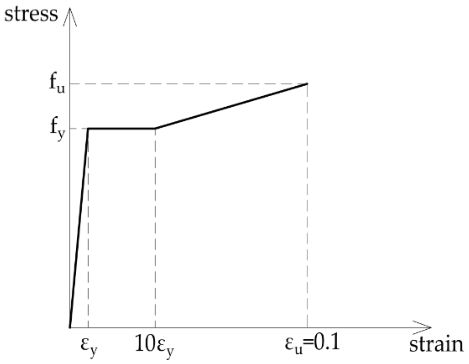
3.2. Steel Material Model

The tri-linear stress–strain model with isotropic hardening from Figure 9 was adopted for the steel tube [21]. Here, fy is the yield strength, εy is the corresponding strain, fu is the specified ultimate tensile strength 490 MPa and εu is the corresponding strain. The Young’s modulus of elasticity for steel was 210 GPa, fy was 355 MPa, while the Poisson’s coefficient was taken as 0.3.

3.3. Constitutive Model for Soil

The stiffness matrices at the top of the piles were obtained from the jacked pile model previously generated in PLAXIS. These values were implemented in ABAQUS within boundary conditions at the CFT column bottom end to simulate the stiffness of the pile–column connection and the effects of the soil–pile interaction.
The numerical model is sensitive to the adopted soil material model and the proper modelling of the whole system at different stages of construction. The soil consisted of three different layers (see Figure 10), and the constitutive soil model was the elastoplastic hardening soil model. The required soil properties were taken from the geotechnical report, as listed in Table 4.
The interface elements at the soil–pile connection correspond to the mechanical characteristics of the soil, multiplied by the Rinter reduction factor. Therefore, the value of the reduction factor was Rinter = 0.8. The finite element mesh was refined around the pile within the area with a dimension equal to four pile diameters.
The soil volume in the model followed the recommendations of Poulos and Davis [28] and Mark F. Randolph and Wroth [29]. Accordingly, the soil inside the cube had a side equal to 2 L, where L is the length of the pile. The external soil nodes had fixed boundary conditions. Figure 10 shows the deformed finite element mesh.
These stiffness coefficients (for horizontal displacement and rotation) appeared to change very slightly during the analysis because of the linear elastic behaviour of soil. Therefore, they can be considered constant. Nevertheless, it should be noted that the pile was already jacked with force several times larger than the critical buckling force of the CFT column.

3.4. Validation of Finite Element Model

The results obtained by the described finite element models for specimens CS1–CS4 are compared to test results.
The top end of the CFT column had pinned support with released movement in the vertical direction. The stiffness at the bottom end of the CFT column was modelled by assigning the corresponding stiffness resulting from the soil–pile analysis from the PLAXIS 3D model.
The buckling analysis was performed to obtain numerical values of critical buckling forces Pcr,num and the effective buckling length of the column Leff. Accordingly, the effective buckling length was measured as the distance between two consecutive points of contra flexure (points of zero moments) in the CFT column.
The median value of the effective column length is 0.799 L. The median value of the ratio between experimentally and numerically obtained buckling force Pcr/Pcr,num is 1.054. As shown in Table 5, there is a good agreement between the numerically obtained results and the experimental results.
The critical buckling forces obtained by the experimental tests are slightly higher than the same forces obtained by the numerical model. These differences are within the range of 3% to 8%.
In addition, Figure 11 shows the numerical results of the deformed shape at failure and horizontal displacements for specimens CS1–CS4. It can be seen that the proposed numerical model can accurately simulate the behaviour of the CFT column supported on the jacked pile.
It should be noted that the experimentally obtained critical buckling force is also compared with the Euler buckling force later in the study, in Section 4. In these comparisons, the effective column stiffness is determined by the proposals from the design codes, and the effective buckling length is taken as 0.8 L.
Furthermore, the validated numerical model was used to investigate the impact of the CFT column—jacked pile connection stiffness on global column stability. The preliminary parametric analysis included three different pile diameters, usually applied during top-down construction: Ø350 mm, Ø450 mm and Ø600 mm were used in the model. The flexibility matrix of the pile top obtained in PLAXIS was applied in ABAQUS within boundary conditions of the lower end of the CFT column for specimens CS1–CS4. The analysis showed that the effective buckling column length remains within the range of 0.72 L–0.86 L, while critical buckling force Pcr,num of the CFT column specimen increases for larger jacked pile diameters (Table 6).
These results show that, for the same soil parameters, the effective buckling length depends on the stiffness (and diameter) of the column and its ratio to the pile dimensions. The larger the diameter of the pile is, the boundary conditions at the column/pile connection are closer to the fixed support. A parameter study that analyses in detail the relations between the column dimensions and the pile dimensions and soil properties is underway.

4. Comparison of Critical Buckling Force with Design Codes

Experimentally obtained buckling forces for the CFT columns NTEST are compared with three design codes: Eurocode 4-EC4 [18], American standard—ACI [30] and the Australian standard—AS [31,32]. The buckling forces were calculated as proposed in design codes but with an experimentally obtained effective column buckling length of 0.8 L. The input parameters for the material characteristics of steel are E = 210 GPa, fy = 355 MPa and the concrete cylinder compressive strength fc’ = 26.70 MPa. Following the EC4, two different stiffnesses are used: results with the effective stiffness of the composite cross-section according to the first-order analysis are denoted as EC4,I, and results with the effective stiffness of the composite cross-section according to the second-order analysis are denoted as EC4,II.
Table 7 compares tests and the results calculated by the design codes: NEC4,I, NEC4,II and NACI/AS.
These differences among the values of the critical buckling forces calculated according to design codes occur due to differences in the stiffness of the composite section. Design codes do not consider the stiffness of the concrete portion of the section in the same way. According to EC4, the stiffness of the uncracked concrete portion of a section is multiplied by a coefficient of 0.6 (in the theory of the first order) or 0.45 (in the theory of the second-order—EC4,II). In ACI/AS calculations, this coefficient is 0.2 (the long-term effects were not considered). Additionally, in EC4,II calculations, the stiffness of the steel tube is decreased by 10% (i.e., multiplied by 0.9).
These results show that buckling forces predicted by the EC4 are more accurate than the results predicted by the ACI and AS. However, the first-order EC4 analysis predictions of critical buckling force are not on the safe side. Therefore, it is advised to perform the second-order EC4 analysis in practice. The ACI and AS codes obtained are the same, on the safe side but slightly more conservative.

5. Conclusions

The paper presents the full-scale testing of CFT column specimens during the top-down construction method. The study aimed to determine the structural behaviour of CFT columns when connected to the previously jacked concrete piles.
Four specimens with different D/t ratios were tested, and the column critical buckling forces and the effective buckling lengths were determined.
Numerical models are generated in PLAXIS and ABAQUS to include the soil–pile–column interaction. The models consider the nonlinear behaviour of steel and concrete in the CFT column and a pile and the nonlinear behaviour of the soil. The comparison between experimental and numerical results has shown good agreement.
The main conclusions of the study are:
  • Experimental and numerical tests demonstrated that the effective buckling column length equals approximately 0.8 L;
  • The preliminary numerical study on the influence of different pile sizes on the CFT column stability was demonstrated that the effective buckling column length remains within the range of 0.72 L–0.86 L. When piles with larger diameters are used compared to the CFT column diameter, the boundary conditions at the column/pile connection are closer to the fixed support. More precise conclusions will be derived from an ongoing study;
  • Referring to the predictions obtained by three design codes (EC4, ACI and AS), they all give good predictions compared to the test results (with effective buckling length taken as 0.8 L). ACI and AS codes are slightly conservative, while the results obtained with the effective stiffness of the composite cross-section according to the first-order analysis (EC4,I) give an unsafe prediction. Therefore, it is recommended that the effective stiffness according to the second-order analysis (EC4,II) be used for accurate predictions and safety reasons.

Author Contributions

Conceptualisation, M.M.L.R., J.Z.N. and S.M.K.; methodology, M.M.L.R., J.Z.N., J.R.R. and S.M.K.; software, M.M.L.R., J.Z.N. and J.R.R.; validation, M.M.L.R., J.Z.N. and J.R.R.; resources, M.M.L.R.; writing—original draft preparation, M.M.L.R. and J.Z.N.; writing—review and editing, M.M.L.R., J.Z.N. and S.M.K.; visualisation, J.Z.N.; supervision, S.M.K.; funding acquisition, M.M.L.R., J.R.R. and S.M.K. All authors have read and agreed to the published version of the manuscript.

Funding

This research received no external funding.

Institutional Review Board Statement

Not applicable.

Informed Consent Statement

Not applicable.

Data Availability Statement

Not applicable.

Acknowledgments

The first, the second and the fourth author thank the Ministry of Science and Technology of the Republic of Serbia for the financial support through project number 2000092.

Conflicts of Interest

The authors declare no conflict of interest.

References

  1. Kostic, S.M.; Filippou, F.C.; Lee, C.-L. An Efficient Beam-Column Element for Inelastic 3D Frame Analysis. In Computational Methods in Earthquake Engineering; Papadrakakis, M., Fragiadakis, M., Plevris, V., Eds.; Springer: Dordrecht, The Netherlands, 2013; Volume 2, pp. 49–67. [Google Scholar]
  2. Zhang, T.; Gong, Y.-Z.; Ding, F.-X.; Liu, X.-M.; Yu, Z.-W. Experimental and numerical investigation on the behavior of concrete-filled rectangular steel tubes under bending. Struct. Eng. Mech. 2021, 78, 231–253. [Google Scholar] [CrossRef]
  3. Agibayeva, A.; Lee, D.; Ju, H.; Zhang, D.; Kim, J.R. Application of steel-concrete composite pile foundation system as energy storage medium. Struct. Eng. Mech. 2021, 77, 753–763. [Google Scholar] [CrossRef]
  4. Dundu, M. Compressive strength of circular concrete filled steel tube columns. Thin-Walled Struct. 2012, 56, 62–70. [Google Scholar] [CrossRef]
  5. Shan, Z.W.; Su, R.K.L. Axial strengthening of RC columns by direct fastening of steel plates. Struct. Eng. Mech. 2021, 77, 705–720. [Google Scholar] [CrossRef]
  6. Uenaka, K. Concrete filled double skin square tubular stub columns subjected to compression load. Struct. Eng. Mech. 2021, 77, 745–751. [Google Scholar] [CrossRef]
  7. Won, D.; Kim, S.; Seo, J.; Kang, Y.-J. Experimental Study of Composite Hollow RC Column under Uniaxial Compressive Load. Appl. Sci. 2019, 9, 373. [Google Scholar] [CrossRef] [Green Version]
  8. Landović, A.; Bešević, M. Experimental Research on Reinforced Concrete Columns Strengthened with Steel Jacket and Concrete Infill. Appl. Sci. 2021, 11, 4043. [Google Scholar] [CrossRef]
  9. Yan, J.-B.; Dong, X.; Zhu, J.-S. Compressive behaviours of CFST stub columns at low temperatures relevant to the Arctic environment. Constr. Build. Mater. 2019, 223, 503–519. [Google Scholar] [CrossRef]
  10. Yan, J.-B.; Dong, X.; Zhu, J.-S. Behaviours of stub steel tubular columns subjected to axial compression at low temperatures. Constr. Build. Mater. 2019, 228, 116788. [Google Scholar] [CrossRef]
  11. Cai, Z.; Wang, Z.; Lin, K.; Sun, Y.; Zhuo, W. Seismic Behavior of a Bridge with New Composite Tall Piers under Near-Fault Ground Motion Conditions. Appl. Sci. 2020, 10, 7377. [Google Scholar] [CrossRef]
  12. Rhim, H.-C.; Kim, K.-M.; Kim, S.-W. Development of an optimum pre-founded column system for top-down construction. J. Civ. Eng. Manag. 2012, 18, 735–743. [Google Scholar] [CrossRef] [Green Version]
  13. Lazovic, M.; Deretic-Stojanovic, B.; Radovanovic, J. Stability of double elastically wedged CFT columns. In Proceedings of the 5th International Congress of Serbian Society of Mechanics, Arandjelovac, Serbia, 15–17 June 2015. [Google Scholar]
  14. Lazovic, M.; Radovanovic, J.; Deretic-Stojanovic, B. Bearing capacity and stability of elastically fixed CFT columns. Tech. Gaz. 2017, 24, 967–973. [Google Scholar] [CrossRef] [Green Version]
  15. Khodair, Y.; Abdel-Mohti, A. Numerical Analysis of Pile–Soil Interaction under Axial and Lateral Loads. Int. J. Concr. Struct. Mater. 2014, 8, 239–249. [Google Scholar] [CrossRef] [Green Version]
  16. Kumar, P.S.; Karuppaiah, K.B.; Parameswaran, P. Buckling behavior of partially embedded reinforced concrete piles in sand. J. Eng. Appl. Sci. 2007, 2, 22–26. [Google Scholar]
  17. De Oliveira, W.L.A.; De Nardin, S.; de Cresce El Debs, A.L.H.; El Debs, M.K. Influence of concrete strength and length/diameter on the axial capacity of CFT columns. J. Constr. Steel Res. 2009, 65, 2103–2110. [Google Scholar] [CrossRef]
  18. EN 1994-1-1; Design of Composite Steel and Concrete Structures—Part 1.1: General Rules and Rules for Buildings, Eurocode 4. European Committeee for Standardization: Bruxelles, Belgium, 2009.
  19. Michael, S. ABAQUS/Standard User’s Manual, Version 6.9; Dassault Systèmes Simulia Corp: Providence, RI, USA, 2009. [Google Scholar]
  20. Plaxis 3D. Scientific Manual; National Academies Press: Washington, DC, USA, 2016. [Google Scholar]
  21. Moon, J.; Roeder, C.W.; Lehman, D.E.; Lee, H.-E. Analytical modeling of bending of circular concrete-filled steel tubes. Eng. Struct. 2012, 42, 349–361. [Google Scholar] [CrossRef]
  22. EN 1992-1-1; Eurocode 2: Design of Concrete Structures—Part 1-1: General Rules and Rules for Buildings. European Committee for Standardization: Bruxelles, Belgium, 2010.
  23. Saenz, L.P. Discussion of Paper “Equation for Stress-Strain Curve of Concrete” by Desai, P. and Krishnan, S.J. Am. Concr. Inst. 1964, 61, 1229–1235. [Google Scholar]
  24. Hu, H.T.; Schnobrich, W.C. Constitutive Modeling of Concrete by Using Nonassociated Plasticity. J. Mater. Civ. Eng. 1989, 1, 199–216. [Google Scholar] [CrossRef]
  25. Hu, H.-T.; Huang, C.-S.; Wu, M.-H.; Wu, Y.-M. Nonlinear Analysis of Axially Loaded Concrete-Filled Tube Columns with Confinement Effect. J. Struct. Eng. 2003, 129, 1322–1329. [Google Scholar] [CrossRef]
  26. Ellobody, E.; Young, B.; Lam, D. Behaviour of normal and high strength concrete-filled compact steel tube circular stub columns. J. Constr. Steel Res. 2006, 62, 706–715. [Google Scholar] [CrossRef]
  27. Tao, Z.; Wang, Z.-B.; Yu, Q. Finite element modelling of concrete-filled steel stub columns under axial compression. J. Constr. Steel Res. 2013, 89, 121–131. [Google Scholar] [CrossRef]
  28. Poulos, H.G.; Davis, E.H. Pile Foundation Analysis and Design; Wiley: New York, NY, USA, 1980. [Google Scholar]
  29. Randolph, M.F.; Wroth, C.P. Analysis of Deformation of Vertically Loaded Piles. J. Geotech. Eng. Div. 1978, 104, 1465–1488. [Google Scholar] [CrossRef]
  30. ACI. Building Code Requirements for Structural Concrete (ACI 318-95)—ACI Committee 318; American Concrete Institute: Farmington Hills, MI, USA, 2011. [Google Scholar]
  31. AS 3600; Reinforced Concrete Structures. Standards Australia: Sydney, Australia, 2009.
  32. AS 4100; Steel Structures. Standards Australia: Sydney, Australia, 2016.
Figure 1. Schematic diagram of the paper flow.
Applsci 12 03771 g001
Figure 2. Steel frame with the hydraulic press for pile jacking.
Applsci 12 03771 g002
Figure 3. General test setup and testing of the specimen CS1.
Applsci 12 03771 g003
Figure 4. Testing of the specimens CS2, CS3 and CS4.
Applsci 12 03771 g004
Figure 5. Pcr-∆L/L relationship for specimens CS1–CS4.
Applsci 12 03771 g005
Figure 6. Position of measuring set on sample CS1.
Applsci 12 03771 g006
Figure 7. Three-dimenional model of CFT column in ABAQUS.
Applsci 12 03771 g007
Figure 8. The constitutive model for concrete.
Applsci 12 03771 g008
Figure 9. The constitutive model for structural steel.
Applsci 12 03771 g009
Figure 10. Finite element mesh for soil.
Applsci 12 03771 g010
Figure 11. Horizontal displacements in the deformed models: (a) CS1; (b) CS2; (c) CS3; (d) CS4;.
Applsci 12 03771 g011aApplsci 12 03771 g011b
Table 1. Specimen dimensions and material properties.
DimensionsD/tL/DConcreteSteel
SpecimenD
[mm]
t
[mm]
L
[mm]
--fc
[MPa]
Ec
[GPa]
fy
[MPa]
E
[GPa]
CS1101.62.7400037.63039.37026.7031.95355210
CS2101.64.0400025.40039.37026.7031.95355210
CS3114.32.7400042.33334.99626.7031.95355210
CS4114.34.0400028.57534.99626.7031.95355210
Table 2. Measured horizontal displacements at 0.35 L, 0.40 L, 0.50 L and the critical buckling force.
SpecimenU0.35L [mm]U0.40L [mm]U0.50L [mm]Pcr [kN]
CS125.3825.7724.16266.7
CS235.0135.5633.34343.0
CS327.2827.7125.98402.9
CS438.8139.4336.97503.8
Table 3. Strain gauge measurements for specimen CS1.
Strain GaugeStrains
M 1.1−444.47·10−6
M 1.2−1807.70·10−6
M 1.3−590.75·10−6
M 1.4−360.00·10−6
Table 4. Soil properties.
PropertyParameterUnitFill (Light Blue)Muddy Clay (Green)Refuelled Sand (Yellow)
The thickness of the soil layerdm6.403.2011.40
Unsaturated weightγunsatkN/m320.0019.0019.00
StiffnessE50refkN/m28000.003000.0030,000.00
EoedrefkN/m28000.003000.0030,000.00
OurrefkN/m224,000.009000.0090,000.00
Poisson ratioνur-0.300.300.30
Powerm-0.500.500.50
Reference pressureprefkN/m2100.00100.00100.00
Cohesionc′kN/m25.0015.005.00
Friction angleφ′°30.0020.0031.00
Dilatancy angleΨ°15.0017.5018.50
Lateral pressure coefficientK0-1-sinφ′
Failure ratioRf- 0.9
Table 5. Comparison of numerical and experimental results for the effective buckling length and buckling force.
SpecimenLeff, num/LPcr,num [kN]Pcr/Pcr,num
CS10.789251.61.060
CS20.795327.31.048
CS30.802373.61.078
CS40.811483.71.042
Median0.799-1.054
Table 6. Numerical results for the effective buckling length and buckling force for different pile diameters for the specimen CS1–CS4.
SpecimenPile Diameters [mm]Leff, num/LPcr,num [kN]
Ø3500.845233.6
CS1Ø4500.789251.6
Ø6000.724273.7
Ø3500.850309.4
CS2Ø4500.795327.3
Ø6000.727356.2
Ø3500.853347.4
CS3Ø4500.802373.6
Ø6000.731406.9
Ø3500.857451.2
CS4Ø4500.811483.7
Ø6000.734528.3
Table 7. Comparison between the buckling force obtained by experiments and calculated by design codes.
SpecimenNTEST/NEC4, INTEST/NEC4, IINTEST/NACI/AS
CS10.9341.0871.141
CS20.9381.0761.074
CS30.9461.1061.182
CS40.9281.0691.081
Median0.9361.0811.111
Publisher’s Note: MDPI stays neutral with regard to jurisdictional claims in published maps and institutional affiliations.

