Article

Ultra-Wideband Bandpass Filters Using Tapered Resonators

1
Electrical Engineering Department, College of Engineering, Prince Sattam Bin Abdulaziz University, Al-Kharj 16278, Saudi Arabia
2
Department of Electrical Engineering, King Saud University, Riyadh 11421, Saudi Arabia
*
Author to whom correspondence should be addressed.
Appl. Sci. 2022, 12(7), 3699; https://doi.org/10.3390/app12073699
Submission received: 21 February 2022 / Revised: 4 April 2022 / Accepted: 5 April 2022 / Published: 6 April 2022

Abstract

:
In this paper, ultra-wideband bandpass filters using tapered transmission line resonators are presented. The proposed filters are based on short-circuited tapered transmission line stubs. The use of tapered transmission resonators resulted in a noticeable length reduction, a wider controlled operational bandwidth, and better stopband characteristics for filter applications. Three filters are designed with different tapered ratios using exponential tapered transmission line resonators. The other three filters are also designed using equivalent linear tapered transmission line resonators. The designed filters are simulated and fabricated on a Roger RT5880 substrate with a 2.2 relative permittivity and 0.78 mm thickness. Approximately, the same performance is obtained using either exponential or linear tapered resonators. A good agreement between the simulated and measured results is reported. The realized 112.22% fractional bandwidth filter has a return loss (S11) better than 17 dB and an insertion loss (S12) better than 1 dB over the entire UWB spectrum. Notable improvements in stopband characteristics are also achieved.

1. Introduction

The Federal Communications Commission (FCC) had authorized the unlicensed use of the ultra-wideband (UWB) frequency spectrum (range of 3.1–10.6 GHz) for short-range and high-speed wireless communication in 2002 [1]. This raised the demand for the design of UWB microwave components. The development of new UWB bandpass filters (BPF) has increased using different methods and configurations [2,3,4,5]. The design of the UWB BPFs focused on compact size, good performance, and low cost. Several configurations of UWB filters are proposed in the literature. Currently, multiple mode resonator (MMR) [6,7,8] and short-circuited stubs [9,10,11,12] are the most common techniques that are widely used in the design of UWB bandpass filters. Several other techniques may also be used in designing UWB filters such as hybrid microstrip/coplanar-waveguide (CPW) [13,14] and cascaded bandpass and band-stop filters [15]. In addition, several approaches are used in the designing of UWB filters with single and dual notch bands for Wi-Fi and Wi-Max applications [16,17,18].
In [6], an UWB filter using MMR is proposed to enable covering the entire UWB bandwidth with 2 dB insertion loss and 10 dB return loss. The filter proposed in [7] is designed using three open-ended stubs in parallel to a stepped-impedance resonator. This results in an UWB BPF with an insertion loss lower than 0.8 dB and a return loss higher than 14.3 dB. A UWB filter using a dual mode resonator had been proposed in [8] with a return loss of 15 dB from 5.7 to 10.7 GHz.
UWB BPFs using five short-circuited stub resonators separated by connecting lines are proposed in different configurations for a 110% fractional bandwidth [9,10]. The authors of [11] presented an UWB BPF, using five short-circuited quarter-wavelength resonators, with a better than 7.5 dB return loss and an insertion loss less than 1.27 dB over the bandwidth from 2.7 GHz to 9.83 GHz. Some additional configurations for UWB BPF can be found in [2,4,5].
In this work, new UWB bandpass filters are proposed. The proposed filters consist of four short-circuited tapered transmission line stubs separated by identical uniform transmission lines. The integration of tapered transmission lines (TTLs) results in element length reduction, and in a wider operational bandwidth that is controlled by the resonator taper ratio. Exponential and linear tapered transmission lines are theoretically analyzed, formulated, and used to design UWB filters. Moreover, UWB LC lumped-element models of the exponential and linear tapered short-circuited stubs are derived and validated.

2. Analysis

The required analysis for the exponential and linear tapered transmission lines used in the design of UWB bandpass filters will be presented in this section. Like the uniform transmission lines, the TTLs can support standing waves with some practical advantages such as shorter lengths and better form factor. Exponential tapered transmission line (ETTL) resonators can, practically, be used in many microwave passive circuits where decreased size and weight, ease of fabrication, and extended coverage of the microwave spectrum are important [19]. There are many published works that had driven the formulas of the minimum length of different ETTL resonators.
The minimum length of a short-circuited ETTL shunt resonator can be derived from the reflection coefficient, which is the solution of the first-order differential equation given by
d r d x 2 γ r + k 2 1 r 2 = 0 ,  
where r is the reflection coefficient, k is the tapered ratio, and γ = j β , where β is the phase constant.
The minimum length of an exponential short-circuited stub is given by [19]
l m i n e x p = tan 1 2 β / k 2 1 1 k / 2 β 2   λ 2 π ,  
where 0 k / β 2 and β = 2 π / λ In addition, λ and k are the waveguide wavelength at the resonant frequency and the ETTL tapered ratio, respectively.
Based on the electrical-equivalence principle of tapered transmission lines [20], the minimum length of an LTTL short-circuited stub can be derived directly from its equivalent ETTL stub as follows:
l m i n l i n = e k l m i n e x p 1 / m ,  
where m is the tapered ratio of the LTTL.
Assuming l m i n l i n is equal to l m i n e x p , then the tapered ratio of LTTL can be found by
m = e k l m i n e x p 1 / l m i n e x p .      
The input impedance of a short-circuited ETTL stub is given by [19]
Z i n e x p = j Z 01 1 k 2 β 2   cot β l 1 k 2 β 2   k 2 β 1 .    
Moreover, the susceptance slope parameter is
b = ω 2 d B d ω ω = ω 0   ,      
where
B = I m 1 Z i n .        
For ETTL, the susceptance slope parameter can be derived and approximately stated as
b e x p β 0 l 2 Z 01 0.85   k 4 β 0 Z 01 .
Therefore, the equivalent lumped inductor and capacitor for the short-circuited ETTL stub are calculated directly as
L e x p = 1 ω 0 b e x p ,  
C e x p = b e x p ω 0 = 1 L ω 0 2 .      
Similarly, for LTTL, the input impedance for the short-circuited stub is given by [21]
Z i n l i n = j Z 01   J 1 a Y 1 b J 1 b Y 1 a J 1 b Y 0 a J 0 a Y 1 b ,
where a = β / m and b = a 1 + m l . J n x and Y n x are the Bessel functions of the first kind and second kind of order n, respectively.
The susceptance slope parameters can be derived and approximately stated by
b l i n β 0 l 2 Z 0 0.81   m 4 β 0 Z 0 .  
Consequently, the equivalent lumped inductor and capacitor for the short-circuited LTTL stub can be determined as
L l i n = 1 ω 0 b l i n ,
C l i n = b l i n ω 0 = 1 L ω 0 2 .  
Figure 1 describes the length reduction in the ETTL short-circuited parallel resonators versus the tapered ratio.

3. Design of Tapered Resonators

In this section, a procedure for the design of short-circuited resonators based on the analysis given in Section 2 will be introduced. For ETTL stubs:
Z 0 i 2 = Z 0 i 1 e k z ,  
where Z 0 i 1 is the impedance at z = 0 ,   Z 0 i 2 is the impedance at z = l m i n e x p , and k is the tapered ratio defined by k = 1 / z ln Z 0 i 2 / Z 0 i 1 . The minimum length of the ETTL stub will be determined using (2), as shown in Figure 2.
For LTTL stubs:
Z 0 i 2 = Z 0 i 1 1 + m z ,
where Z 0 i 1 . is the impedance at z = 0 , and Z 0 i 2 is the impedance at z = l m i n l i n .
The wavelength λ is not constant along the taper. Hence, to determine the effective wavelength, the effective dielectric constant ε e of the ETTL is approximated as the average effective dielectric constant of wide and narrow lines [22] then
ε e = ε e 1 + ε e 2 2 ,  
where ε e 1 is the effective dielectric constant of the line with characteristic impedance Z 0 i 1 , and ε e 2 is effective dielectric constant of the line with characteristic impedance Z 0 i 2 . The effective wavelength is then given by
λ = c f 0 ε e ,
where f 0   is the center frequency, and c is the velocity of light. In the same manner, the above procedure can be applied for the LTTL shown in Figure 3.
Table 1 shows the elements that can be used in the design of both the exponential and the linear tapered short-circuited shunt resonators for three different k / β 0 ratios.

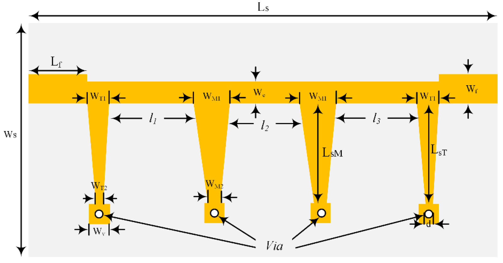
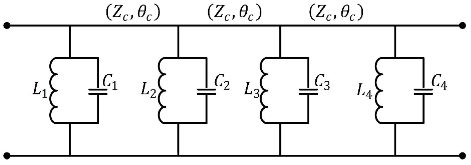
4. UWB Bandpass Filter Design

In this section, UWB bandpass filters are designed. The UWB filter configuration adopted in this paper is the conventional UWB structure based on optimum high-pass filter structure [19]. This filter consists of short-circuited uniform stubs which can be designed to cover the UWB spectrum. For n = 4 the filter consists of four short-circuited transmission line stubs with characteristic impedances of Z01, Z02, Z03, and Z04 with electrical lengths of θs separated by connecting lines of electrical length θc = 2θs, as shown in Figure 4. To simplify the design, we selected the impedance values as Z01 = Z04, Z02 = Z03, and Z01 = 2Z02. In the proposed design, tapered transmission line stubs are used to replace the uniform short-circuited stub in the classical design, as shown in Figure 5. The characteristic impedances of the tapered transmission line stubs vary from Z0i1 to Z0i2 (i = 1,2,3,4) where Z011 = Z041, Z021 = Z031, and Z011 = 2Z021. The electrical lengths of the tapered short-circuited stubs are less than half of the connecting lines, i.e., θs ≤ θc/2.
UWB BPFs of a fractional bandwidth of 110% is designed to cover the entire bandwidth (3.1–10.6 GHz). The characteristic impedances are determined as Zc = 55 Ω, Z011 = Z041 = 112 Ω, and Z021 = Z031 = 56 Ω. Equations (15) and (16) are used to determine the value of Z 0 i 2 for ETTL and LTTL, respectively. For kβ0 = 0.25 exponential tapered transmission line short-circuited stubs, the resulting impedances are Z012 = Z042 = 161.3 Ω, and Z022 = Z032 = 80.6 Ω. For kβ0 = 0.375 stubs, the impedances are Z012 = Z042 = 189.8 Ω, and Z022 = Z032 = 94.9 Ω. For kβ0 = 0.5 stubs, the impedances are Z012 = Z042 = 221.8 Ω, and Z022 = Z032 = 110.9 Ω.
The layout of the proposed UWB bandpass filter is shown in Figure 6. The filter is simulated and fabricated on a Roger RT5880 substrate with a relative dielectric constant equal to 2.2 and a thickness of 0.78 mm. The parameters of the proposed microstrip filters are given in Table 2.
The semi-lumped equivalent circuit of the tapered short-circuited stubs filter can be determined by replacing the short-circuited tapered stubs with its lumped LC equivalent resonator, as shown in Figure 7. The equivalent inductances and capacitances can be calculated from (9) and (10) for the ETTL and from (13) and (14) for the LTTL. The values of the equivalent inductances and capacitances for the ETTL shunt stubs at f 0 = 6.85 GHz are given in Table 3. Figure 8 shows the response of the semi-lumped equivalent filter of ETTL stubs where k / β 0 = 0.25 . The results of the lumped circuit equivalence of the tapered short-circuited resonators calculated from (9) and (10) demonstrate the filter performance over the entire band (3.3 GHz—11 GHz).

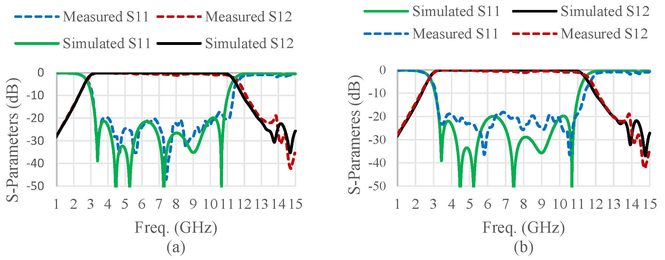
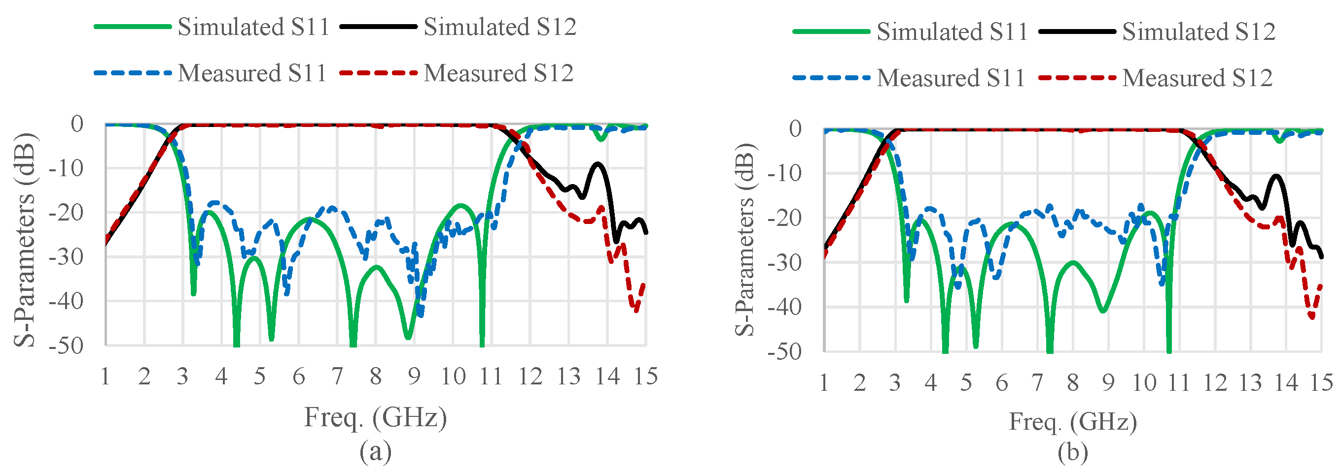
5. Results and Discussion

The filters proposed and analyzed in the previous section were simulated using the CST software tools with a time-domain solver and waveguide ports. A Roger RT5880 substrate with a 2.2 relative permittivity, 0.78 mm thickness, and 0.0009 loss tangent was used for this purpose. Then, the designed filters were fabricated and experimentally characterized. The proposed microstrip UWB bandpass filter shown in Figure 6 was fabricated, with the parameters listed in Table 2, using a laser etching system. The experimental results were obtained using the Anritsu Vector Network Analyzer. The simulated and measured results were compared for various k/β0 ratios. The simulated and measured responses of k/β0 = 0.25 filter with ETTL short-circuited resonator are shown in Figure 9a. However, the simulated and measured responses of the filter with equivalent LTTL are shown in Figure 9b. The measured return loss S 11   of both designed filters is better than 17.5   dB over the bandwidth extended from 3.24 GHz to 10.88 GHz (the fractional bandwidth of 108.22%), and the insertion loss S 12 is better than 1.25   dB over the entire bandwidth for both the exponential and the linear stubs filters.
Furthermore, the simulated and measured results of   k / β 0 = 0.375 filters with ETTL and LTTL are shown in Figure 10a,b, respectively. Here, the measured return loss is better than 17.3   dB over the bandwidth extended from 3.11 GHz to 10.95 GHz (the fractional bandwidth of 111.52%) and the insertion loss is better than 1   dB over the entire bandwidth for both tapered stubs.
In addition, for   k / β 0 = 0.50 , the return loss is better than 17   dB and the bandwidth extends from 3.09 GHz to 10.99 GHz (the fractional bandwidth of 112.22%) with an insertion loss less than 0.8   dB over the entire bandwidth for both stubs, as shown in Figure 11.
Moreover, the obtained measurement results show a group delay that is almost flat over the entire passband bandwidth, as can be seen in Figure 12. The measured group delay is less than 0.8 ns and measured directly using the vector network analyzer. The photograph of the fabricated filter with k / β 0 = 0.25 is shown in Figure 13.
Table 4 demonstrates a performance comparison with UWB filters designed using different techniques. The selected filters are designed to meet the required frequency range (3.1 GHz—10.60 GHz) provided by the FCC. From Table 4, it is found that the proposed UWB bandpass filters provide the widest bandwidth (112.22%) compared with other techniques. Additionally, the proposed UWB filters attain the minimum insertion loss (−0.8 dB), high return loss (−17 dB), and can be designed and fabricated simply.

6. Conclusions

In this paper, new UWB microwave bandpass filters based on exponential and linear short-circuited tapered transmission line stub resonators are analyzed and modeled. The proposed filters are then designed, simulated and fabricated to demonstrate the analytical circuit model of the tapered resonators. Significant improvements in the proposed UWB filters have been reported in the bandwidth, performance, and size reduction due to the proper integration of the tapered transmission line stubs. The operational bandwidth of the UWB filters can be pre-controlled by the tapered ratio of the filter resonators as demonstrated by the simulated and measured results. The analytically determined, simulated, and measured responses of the designed exponential and linear tapered resonator filters are in good agreement. Additionally, the fractional bandwidth of the realized UWB bandpass filter is 112.22%. The performance measures of the proposed UWB filters are summarized and compared with similar structures in Table 4.

Author Contributions

Conceptualization, F.R. and M.A.S.A.; methodology, F.R. and M.A.S.A.; software, F.R.; validation, F.R.; formal analysis, M.A.S.A., F.R. and S.M.S.; investigation, F.R. and S.M.S.; resources, F.R. and. M.A.S.A.; data curation, F.R.; writing—original draft preparation, F.R.; writing—review and editing, F.R., M.A.S.A. and S.M.S.; visualization, F.R. and S.M.S.; supervision, M.A.S.A.; project administration, F.R.; funding acquisition, F.R. All authors have read and agreed to the published version of the manuscript.

Funding

The authors extend their appreciation to the Deputyship for Research & Innovation, Ministry of Education in Saudi Arabia for funding this research work through the project number IF-PSAU-2021- 01/18746.

Institutional Review Board Statement

Not applicable.

Informed Consent Statement

Not applicable.

Data Availability Statement

The data that support the findings of this study are available upon reasonable request from the corresponding author.

Conflicts of Interest

The authors declare no conflict of interest.

References

  1. Federal Communications Commission. Federal Communications Commission Revision of Part 15 of the Commission’s Rules Regarding Ultra-Wideband Transmission System from 3.1 to 10.6 GHz; Federal Communications Commission: Washington, DC, USA, 2002. [Google Scholar]
  2. Hao, Z.-C.; Hong, J.-S. Ultrawideband filter technologies. IEEE Microw. Mag. 2010, 11, 56–68. [Google Scholar] [CrossRef]
  3. Jamsai, M.; Angkawisittpan, N.; Nuan-On, A. Design of a compact ultra-wideband bandpass filter using inductively compensated parallel-coupled lines. Electronics 2021, 10, 2575. [Google Scholar] [CrossRef]
  4. Shome, P.P.; Khan, T.; Koul, S.K.; Antar, Y.M. Two Decades of UWB Filter Technology: Advances and Emerging Challenges in the Design of UWB Bandpass Filters. IEEE Microw. Mag. 2021, 22, 32–51. [Google Scholar] [CrossRef]
  5. Sun, S.; Zhu, L. Multiple-resonator-based bandpass filters. IEEE Microw. Mag. 2009, 10, 88–98. [Google Scholar] [CrossRef]
  6. Zhu, L.; Sun, S.; Menzel, W. Ultra-wideband (UWB) bandpass filters using multiple-mode resonator. IEEE Microw. Wirel. Compon. Lett. 2005, 15, 796–798. [Google Scholar]
  7. Li, R.; Zhu, L. Compact UWB bandpass filter using stub-loaded multiple-mode resonator. IEEE Microw. Wirel. Compon. Lett. 2007, 17, 40–42. [Google Scholar] [CrossRef]
  8. Song, K.; Fan, Y. Compact ultra-wideband bandpass filter using dual-line coupling structure. IEEE Microw. Wirel. Compon. Lett. 2008, 19, 30–32. [Google Scholar] [CrossRef]
  9. Shaman, H.; Hong, J.-S. A novel ultra-wideband (UWB) bandpass filter (BPF) with pairs of transmission zeroes. IEEE Microw. Wirel. Compon. Lett. 2007, 17, 121–123. [Google Scholar] [CrossRef]
  10. Shahrazel Razalli, M.; Ismail, A.; Adzir Mahdi, M.; Nizar Hamidon, M. Ultra-wide band microwave filter utilizing quarter-wavelength short-circuited stubs. Microw. Opt. Technol. Lett. 2008, 50, 2981–2983. [Google Scholar] [CrossRef]
  11. Razalli, M.S.; Ismail, A.; Mahdi, M.A.; bin Hamidon, M.N. Novel compact microstrip ultra-wideband filter utilizing short-circuited stubs with less vias. Prog. Electromagn. Res. 2008, 88, 91–104. [Google Scholar] [CrossRef] [Green Version]
  12. Hong, J.-S. Microstrip Filters for RF/Microwave Applications; John Wiley & Sons: Hoboken, NJ, USA, 2011. [Google Scholar]
  13. Thomson, N.; Hong, J.-S. Compact ultra-wideband microstrip/coplanar waveguide bandpass filter. IEEE Microw. Wirel. Compon. Lett. 2007, 17, 184–186. [Google Scholar] [CrossRef]
  14. Kuo, T.-N.; Lin, S.-C.; Chen, C.H. Compact ultra-wideband bandpass filters using composite microstrip–coplanar-waveguide structure. IEEE Trans. Microw. Theory Tech. 2006, 54, 3772–3778. [Google Scholar] [CrossRef]
  15. Tang, C.-W.; Chen, M.-G. A microstrip ultra-wideband bandpass filter with cascaded broadband bandpass and bandstop filters. IEEE Trans. Microw. Theory Tech. 2007, 55, 2412–2418. [Google Scholar] [CrossRef]
  16. Shaman, H.; Hong, J.-S. Ultra-wideband (UWB) bandpass filter with embedded band notch structures. IEEE Microw. Wirel. Compon. Lett. 2007, 17, 193–195. [Google Scholar] [CrossRef]
  17. Guan, X.; Gui, P.; Xiong, T.; Ren, B.; Zhu, L. Hybrid microstrip/slotline ultra-wideband bandpass filter with a controllable notch band. Int. J. Antennas Propag. 2017, 2017, 2398610. [Google Scholar] [CrossRef] [Green Version]
  18. Zheng, X.; Jiang, T. Realization of dual notch bands in UWB bandpass filter using two T-shaped resonators. In Proceedings of the 2017 International Applied Computational Electromagnetics Society Symposium-Italy (ACES), Firenze, Italy, 26–30 March 2017; pp. 1–2. [Google Scholar]
  19. Womack, C.P. The use of exponential transmission lines in microwave components. IRE Trans. Microw. Theory Tech. 1962, 10, 124–132. [Google Scholar] [CrossRef]
  20. Holt, A. General principle of electrical equivalence for nonuniform transmission lines. Electron. Lett. 1969, 5, 143–144. [Google Scholar] [CrossRef]
  21. Rustogi, O. Linearly Tapered Transmission Line and Its Application in Microwaves (Correspondence). IEEE Trans. Microw. Theory Tech. 1969, 17, 166–168. [Google Scholar] [CrossRef]
  22. Mathur, S.; Sinha, A.K.; Sinha, A. Design of microstrip exponentially tapered lines to match helical antennas to standard coaxial transmission lines. IETE Tech. Rev. 1988, 5, 426–429. [Google Scholar] [CrossRef]
  23. Shome, P.P.; Khan, T. A compact design of circular ring-shaped MMR based bandpass filter for UWB applications. In Proceedings of the 2019 IEEE Asia-Pacific Microwave Conference (APMC), Singapore, 10–13 December 2019; pp. 962–964. [Google Scholar]
  24. Shaman, H.; Hong, J.-S. An optimum ultra-wideband (UWB) bandpass filter with spurious response suppression. In Proceedings of the 2006 IEEE Annual Wireless and Microwave Technology Conference, Clearwater Beach, FL, USA, 4–5 December 2006; pp. 1–5. [Google Scholar]
  25. Djeddi, T.; Elsaadany, M.; Shams, S.; Hamouda, W. Compact ultra-wideband printed bandpass filter based on coupled-line resonator loading. In Proceedings of the 2018 18th International Symposium on Antenna Technology and Applied Electromagnetics (ANTEM), Waterloo, ON, Canada, 19–22 August 2018; pp. 1–2. [Google Scholar]
  26. Ye, J.-D.; He, L.; Zhong, X.-J.; Qu, D.-X. Design of ultra-wideband bandpass (UWB) filter with enhanced couplings by using lumped capacitors. In Proceedings of the 2018 International Conference on Microwave and Millimeter Wave Technology (ICMMT), Chengdu, China, 7–11 May 2018; pp. 1–3. [Google Scholar]
  27. Jhariya, D.K.; Mohan, A.; Sinha, M. Design of two-stage fish spear-shaped UWB bandpass filter with sharp selectivity and good out-of-band performances. Int. J. Microw. Wirel. Technol. 2017, 9, 1821–1826. [Google Scholar] [CrossRef]
  28. Ghazali, A.N.; Sazid, M.; Virdee, B. A compact UWB-BPF based on microstrip-to-CPW transition with multiple transmission zeros. Microw. Opt. Technol. Lett. 2018, 60, 1925–1928. [Google Scholar] [CrossRef]
  29. Xie, J.; Tang, D.; Shu, Y.; Luo, X. Compact UWB BPF With Broad Stopband Based on Loaded-Stub and C-Shape SIDGS Resonators. IEEE Microw. Wirel. Compon. Lett. 2021, 1–4. [Google Scholar] [CrossRef]
  30. Shome, P.P.; Khan, T. A quintuple mode resonator based bandpass filter for ultra-wideband applications. Microsyst. Technol. 2020, 26, 2295–2304. [Google Scholar] [CrossRef]
Figure 1. Minimum length of short-circuited ETTL shunt resonator.
Applsci 12 03699 g001
Figure 2. Exponential TTL short-circuited stub.
Applsci 12 03699 g002
Figure 3. Linear TTL short-circuited stub.
Applsci 12 03699 g003
Figure 4. Conventional UWB bandpass filter structure with uniform short-circuited stubs of length θs and uniform impedance Z01 and Z02.
Applsci 12 03699 g004
Figure 5. Modified UWB bandpass filter structure with TTL short-circuited stubs of length θs and tapered impedance Z012 = Z042 and Z032 = Z022.
Applsci 12 03699 g005
Figure 6. Layout of the proposed microstrip UWB bandpass filters with tapered resonators.
Applsci 12 03699 g006
Figure 7. UWB filter with LC equivalent resonators.
Applsci 12 03699 g007
Figure 8. Simulated S−parameters results of the lumped element filter represented in Figure 7.
Applsci 12 03699 g008
Figure 9. Simulated and measured S-parameters of the proposed UWB filters (represented in Figure 6). (a) ETTL of   k / β 0 = 0.25 . (b) Equivalent LTTL.
Applsci 12 03699 g009
Figure 10. Simulated and measured S-parameters of the proposed filters (represented in Figure 6). (a) ETTL of   k / β 0 = 0.375 . (b) Equivalent LTTL.
Applsci 12 03699 g010
Figure 11. Simulated and measured S-parameters of the proposed filters (represented in Figure 6). (a) ETTL of   k / β 0 = 0.50 . (b) Equivalent LTTL.
Applsci 12 03699 g011
Figure 12. Measured group delay of the designed UWB ETTL filter of   k / β 0 = 0.50 .
Applsci 12 03699 g012
Figure 13. Photograph of the designed UWB BPF.
Applsci 12 03699 g013
Table 1. Parameters of tapered stubs.
k/β00.250.3750.50
lmin0.232 λ0.224 λ0.212 λ
Z0i21.44 Z0i11.695 Z0i11.98 Z0i1
Table 2. Dimensions of the elements of the designed filters (millimeters).
k/β00.250.3750.50
l114.9214.9214.92
l214.1714.1714.17
l314.9214.9214.92
Terminal
stub widths
WT10.510.510.51
WT20.160.080.03
Middle
stub widths
WM12.002.002.00
WM21.100.800.53
Lengths of the terminal
stubs (LsT)
7.276.866.51
Lengths of the middle
stubs (LsM)
7.036.636.28
Wc2.07
Wv0.7
Wf2.4
Radius of vias0.25
Ws20
Ls59.03
Lf5
Table 3. Equivalent lumped elements.
k/β00.250.3750.50
L1 = L4 (nH)3.854.144.44
L2 = L3 (nH)1.932.072.22
C1 = C4 (pF)0.140.130.12
C2 = C3 (pF)0.280.260.24
Table 4. Performance comparison with other UWB filter techniques.
ReferencePassband (GHz)Bandwidth (GHz)Insertion Loss (dB)Return Loss (dB)Techniques
[3]2.92–10.958.03 (107.0%)−0.49−12.0ICPCL
[15]3.06–10.06.94 (106.3%)−1.00−13.0Cascaded bandpass and bandstop filters
[23]3.05–10.627.57 (100.9%)−1.50−13.0MMR
[24]3.1–10.67.5 (110.0%)No data−11.0Short-circuited stubs
[25]2.50–7.004.5 (60.0%)No Data−23.0CLR
[26]3.00–10.27.20 (96.0%)−2.00−14.9Lumped capacitors
[27]3.20–11.708.50 (114.0%)−1.50−12.0MMR
[28]3.12–10.697.57 (109.6%)−1.20−12.7MMR
[29]2.95–10.757.80 (113.9%)−0.60−14.0SIDGS
[30]3.21–10.777.56 (109.4%)−0.80No DataMMR
This work k / β 0 = 0.250 3.24–10.887.64 (108.22%)−1.25−17.5Short-circuited tapered resonators
k / β 0 = 0.375 3.11–10.957.84 (111.52%)−1.00−17.3
k / β 0 = 0.500 3.09–10.997.90 (112.22%)−0.80−17.0
Publisher’s Note: MDPI stays neutral with regard to jurisdictional claims in published maps and institutional affiliations.

