1. Introduction
The AC-AC power converters based on the switching action of the solid-state devices allow the grid’s constant voltage and frequency to vary as per the requirement. The variation in the grid frequency and voltage is required for a heating process through the induction phenomena, speed drive, and controlled power conversion from AC to DC and voltage correcting set up in a power distribution system. There are two basic AC power converting topologies, called indirect and direct conversion. The first approach is based on multistage power conversion that may include the conversion from AC to DC, DC to DC, and DC to AC. This approach is limited nowadays as it has some serious concerns such as the high value of the overall weight, losses, volume, cost, and an increase in system complexity [
1,
2,
3]. In these converters, there is also the problem of low power factor and high value of the harmonic factor of output voltage and input current that requires harmonic elimination filters. The use of a DC-link capacitor curtails the reliability of the entire system.
The limitations of the indirect AC converters are addressed in the converters based on the direct AC power conversion approaches. There is no concern about the system’s reliability as there is no DC link stage. These converters are more attractive for applications that only require low output frequency in variable form. These applications include rolling in a steel manufacturing process, grinding systems for mining, and electrical traction systems [
4,
5,
6]. Traditionally, the single-phase cycloconverters are used as a direct frequency regulator without involving the DC power stage. Still, its implementation requires more solid-state devices and corresponding gate control circuits. Conventionally, the cycloconverters are developed with thyristors. Nowadays, however, these devices are replaced with soft switching devices (transistors). The frequency controllers based on the high switching operation of the operating devices can govern the output frequency and rms voltage. The described circuit is one of the modified versions of AC converters that utilize a Z-source circuit for shoot-through compensation and voltage regulation. Such topologies are reported in [
7,
8,
9,
10]. The circuit and control complications are the main concern in these topologies. Their realization needs a large number of circuit elements and solid-state devices. The current rating of these components has to increase as there is a flow of high surges of current during the shoot-through intervals. The protection circuits for operating devices are needed as there is induction of high voltage and current surges.
The operating issues of the Z-source circuits are addressed in the other form of AC-AC topologies that do not need to use the Z-source structure in their implementation [
11,
12,
13,
14]. These topologies can produce the regulated voltage of dual polarity required for output frequency control. The circuit stated in [
11] requires six fast switching transistors and diodes, but its dual polarity voltage operation is non-symmetrical. Also, the issue of high voltage in these converters remains unaddressed. This problem is figured out in [
13] by introducing various operating modes, but their control for dual polarity voltage operation remains non-symmetrical. The symmetry in the dual polarity voltage operation with a low operating voltage is ensured in the converter stated in [
12]. However, the circuit realization of this topology needs eight transistors and eight fast switching diodes, thus increasing the overall weight, losses, and cost. Although all of the topologies stated in [
11,
12,
13] can effectively be operated to produce low and high output frequency, their operational control schemes seem to be complex. Such power conversion approaches are not well suited for applications that just need frequency regulation.
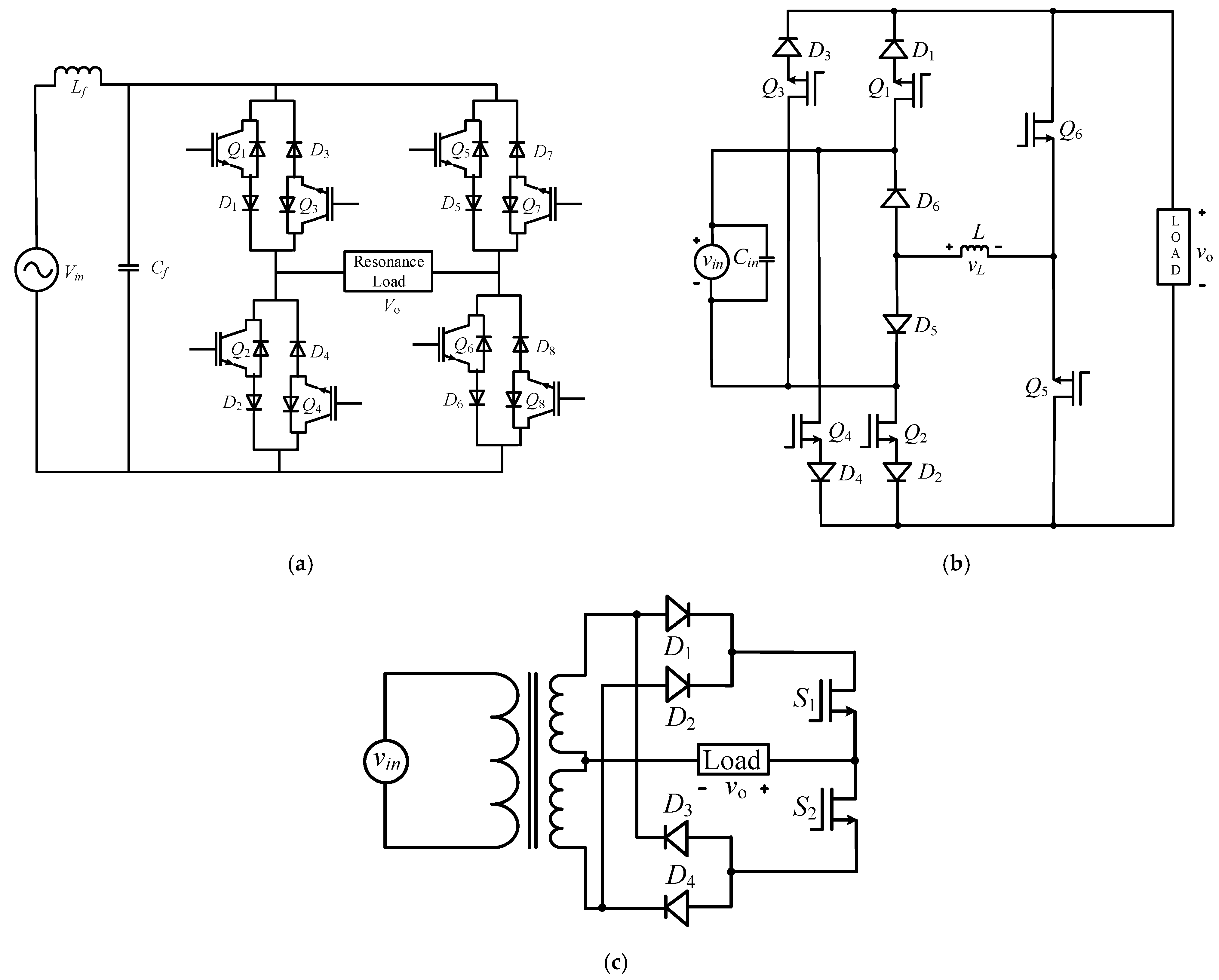
Various circuits are stated in literature to govern the output frequency by employing the direct form of the AC-AC converters. The circuit described in [
15] has a dual H-bridge, as shown in
Figure 1a, to regulate the output frequency at a discrete level by employing a simpler control technique. One control input is generated by using Arduino UNO as a signal generator, ensuring the alignment of the signal to the input AC voltage. For this purpose, the output of the source voltage polarity sensing circuit is connected to an input port of the Arduino controller. A NOT gate is connected with the output port of the signal to obtain the inverted or complementary form of this signal. So, there are two signals whose control logic is complementary in nature. Each control input is converted to four signals with the help of gate control circuits to govern the operating states of the eight switching transistors. The principal issue in this circuit is the use of large components and specially controlled solid electronic devices. Since it is not possible to govern the on and off behavior of a transistor directly with control input generated by the Arduino or some other signal controller. For this purpose, the use of gate control circuits is a fundamental requirement, and their numbers are proportional to the number of operating transistors. The cost, weight, and size of such circuit arrangement are normally much more than that of an operating transistor. The authors of the circuit reported in [
16] (see
Figure 1b) succeeded in reducing the use of two fast switching transistors and two diodes. Surely, the reduction of two transistors mitigates the need for two driving circuits. This would help to tackle the issue of space and weight. The research in [
17] further simplifies the control effort by reducing the four more switching transistors, as shown in
Figure 1c. This feature is achieved with an increase of two additional diodes. The total losses produced by the switching devices in [
17] are low than in [
16]. Although this topology simplifies the circuit in terms of devices and components, the use of a bulky source frequency transformer is a significant problem in terms of losses, weight, and cost.
The circuits reported in [
16,
17] can change the input frequency at the load terminal to a low value in discrete steps, that is one-half, one-third, or one-fourth of the input frequency. This variation in the output frequency is achieved with the help of the non-inverted and inverted forms of the input voltage. The ultimate role of the frequency controller is to keep the number of positive half cycles for the first half period of the output voltage and the number of negative half cycles for the second half period of the output voltage. These positive and negative half-cycles in one output period are equal, and their numbers depend on the required output frequency. For example, there are two consecutive positive and two negative half-cycles for the requirement where the output frequency is one-half of the input. There is a series of three and four positive and negative half-cycles for the application that requires the frequency of one-third and one-fourth of the input frequency, respectively. This sort of output always exists in non-sinusoidal forms and contains unwanted components called harmonics. The harmonic coefficients of these output voltage waveforms are numerically computed in [
18] to explore their power quality drawbacks. Then it is investigated that the harmonic factor of the output voltage is nearly 60%, 67%, and 70% for an output frequency of one-half, one-third, and one-fourth of input frequency, respectively. So, the output voltage quality decreases once their output frequency is reduced in discrete steps.
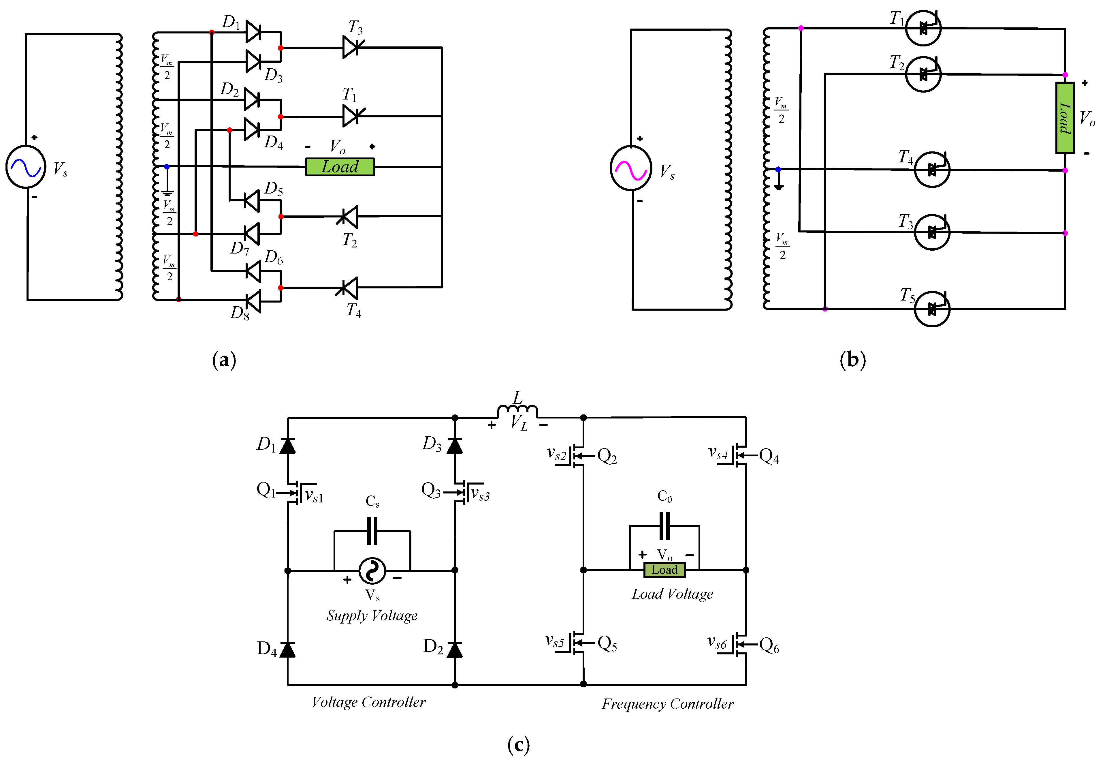
This issue intends to tackle by adjusting the magnitude of some selected half cycles of output voltage. The harmonic factor of the output voltage for one-third and one-fourth frequency requirement is reduced to approximately 55% by regulating the amplitude of some selected output half cycles as described in [
19,
20]. The circuit diagram of these converters is illustrated in
Figure 2a,b. The circuit describes in [
19] needs eight diodes and four thyristors. However, the realization of a converter in [
20] uses five Triacs or ten thyristors. These converters cannot be implemented without using a bulky low-frequency multi-winding transformer. The use of this transformer is absent in the converter described in [
21]. This setup is shown in
Figure 2c wherein the voltage adjustment of the output half cycles is governed through the high-frequency PWM control.
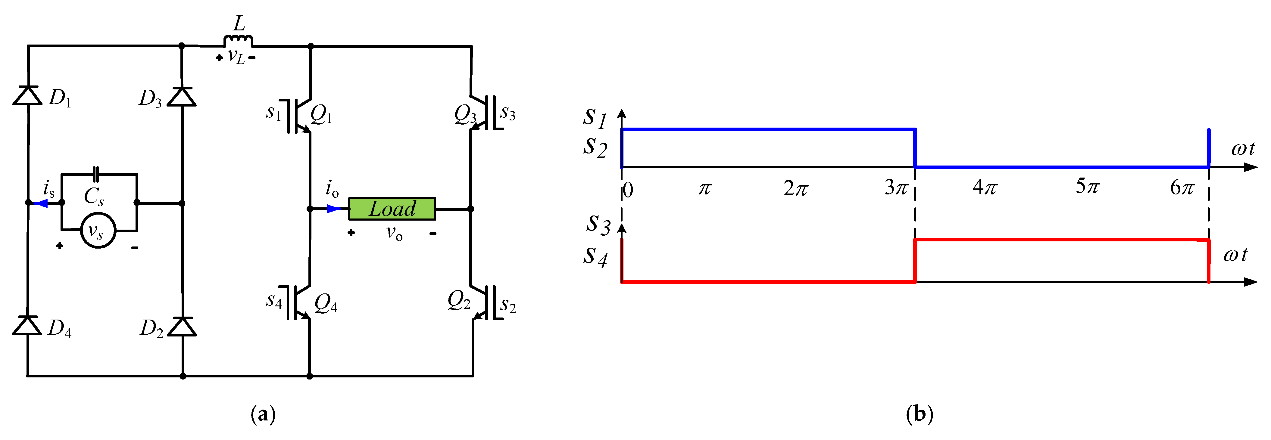
The output half-cycle voltage control approach cannot improve power quality for some output frequencies. For example, there is no way to lower the harmonic factor of the output voltage for the frequency requirement of one-half of the input frequency. The improvement in the harmonic factor of output voltage for other output frequency requirements introduces the low-frequency harmonics in the input current. That degrades the input power quality indexes severely by increasing the input current harmonic factor and lowering the input power factor. So, the input side gets more harmonic pollution than the power quality improvement of the output voltage. In existing converters, the concerns related to the power quality of the output voltage are addressed, but this concern for input current is not yet explored in the literature. The added harmonic pollution in the input current needs more investigation. So, in this research article, these power quality concerns of output voltage and input current are numerically addressed in detail. The harmonic investigation of the input current and output voltage recognizes that decrement in the HF of output voltage severely increases the HF of the input current. This conclusion suggests that for low-frequency applications, the improvement in the input power quality indexes is ensured by eliminating the variation of the output half cycles. In this regard, our already proposed high-frequency controller in [
22] can also be effectively be employed for low output frequency operation. The only modification in this circuit is that one input voltage polarity sensing circuit has to be included to align the control inputs with the source voltage to detect its variation. Its output may be used by any signal generator to synchronize its generated signal with the polarity of the input voltage. All operational modes of the circuit of
Figure 3a are comprehensively described in [
22]. The use of the rectifier’s bridge enables the input alternating voltage to convert into its absolute form by non-inverting and inverting all input positive and negative half-cycles, respectively. The role of the inverter’s bridge is to arrange the absolute value pulses into the required frequency AC form. The control signal that enables to obtain the load frequency to one-third compared to input may be seen in
Figure 3b.
In summary, the following are the main issues or research gaps in the circuit topologies that improve the power quality-related concerns of the output voltage obtained via the magnitude control of the selected half cycles.
It is not possible to improve the harmonic profile of the output voltage for the output frequency that is one-half of the input.
Improvement in the harmonic profile of the output voltage adds unwanted harmonic components in the input current, and this issue is not yet investigated according to the authors’ best knowledge or information.
Circuit topologies for the low frequencies control without the voltage adjustment control of the output need a number of components or devices and these are complex to realize.
The research contribution of this manuscript is highlighted in a better way keeping in view the above-stated research gap or deficiencies in the existing circuit topologies.
The concerns related to power quality are numerically investigated by using pulse selected approach for output frequency, which is one-half of the input. Here, it is concluded that it is not possible to improve the harmonic profile via the regulation of some selected half cycles or pulses of the output voltage. The minimum harmonic factor, in this case, is 62% that can only be ensured without pulse voltage adjustment.
It is also investigated through a pulse selective method whether improving the power quality of the output voltage severely degrades the power quality of the input current. For example, a 15% decrement of a harmonic factor in the output voltage for one-third or one-fourth of input frequency results in an increase of 35% increase in the harmonic factor of the input currents.
The issues related to the use of a large number of components or devices and complications in the circuit implementation are tackled with the help of some modifications in our previously developed frequency control circuit that is used as a high-frequency controller as in [
22]. This is one of the simplest and cheapest ones compared to existing circuits in terms of circuit complexity and the number of devices and components.
The numerical analysis of the harmonic contents is addressed in
Section 2. The validation of the tested circuit is carried out via the results gained from computer simulation in Simulink and practical results in
Section 3 and
Section 4, respectively.
Section 5 provides the conclusions of our research.
2. Numerical Analysis of Generated Harmonics
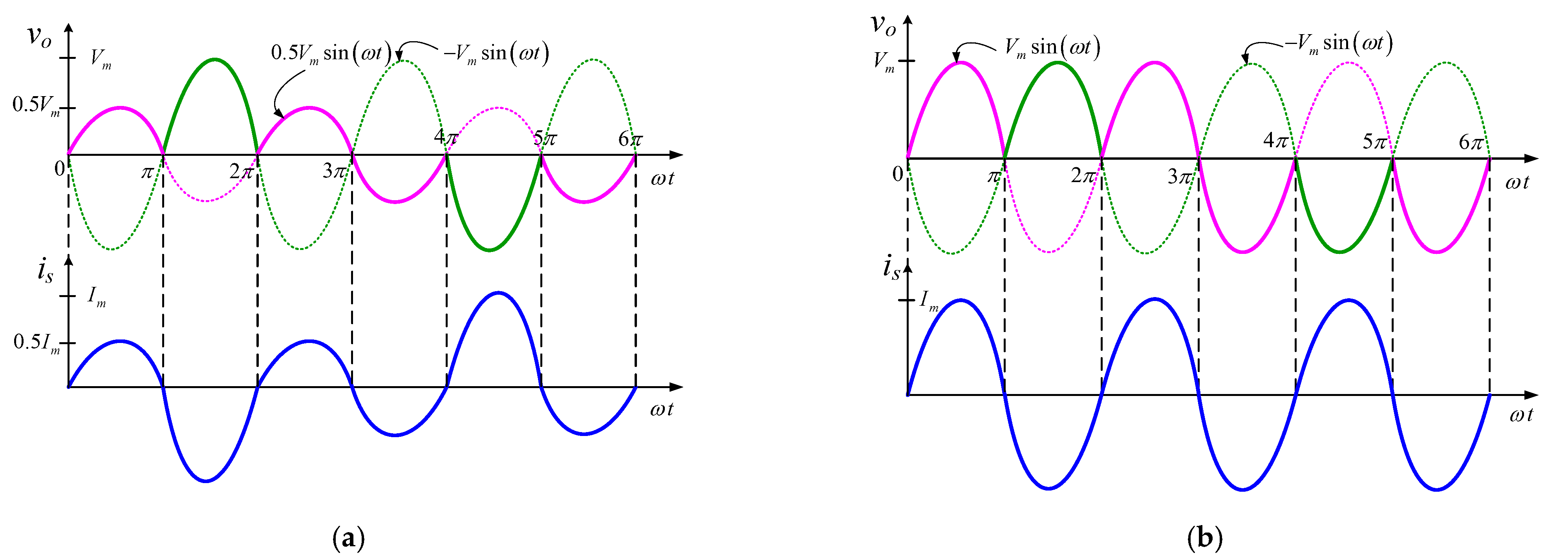
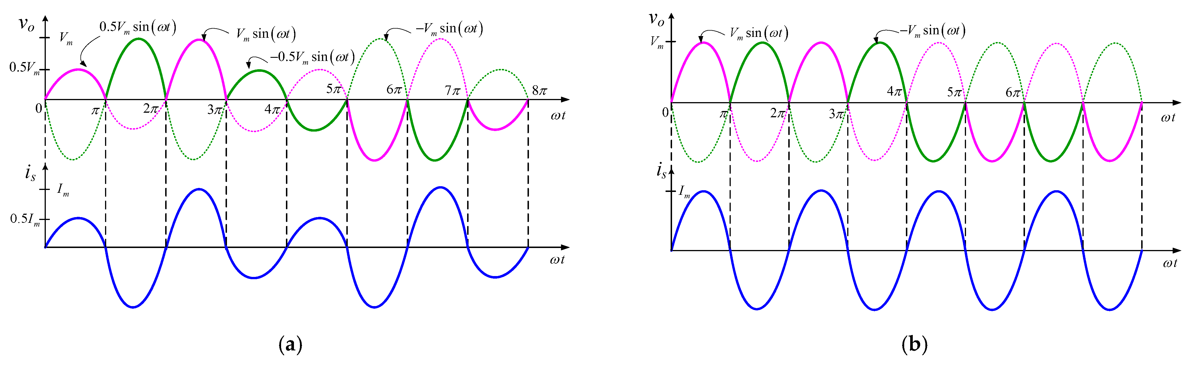
The regulation in the output frequency at the discrete level is ensured with the proper arrangement of a non-inverted and inverted form of the input half-cycles at the output. The half frequency output that is one-half of the input frequency with pulse voltage adjustment control, is shown in
Figure 4a. In this waveform, the second and third half cycles of the first and second cycles of the input voltage are inverted at the output without any voltage adjustment. Their second and fourth half-cycles remain non-inverted at the output, but their magnitude is one-half with respect to the input. The values of the output pulses are described in mathematical form, as can be seen in Equation (1).
The pulse selective technique, as described in [
18], is useful for analyzing the output voltage and input current in terms of their rms values and harmonic indexes. In this regard, first the output voltage is taken for this purpose. Here ‘
k’ is the magnitude scaling factor of the output voltage-controlled pulses and its value may be adjusted from ‘0’ to ‘1’.
The Fourier series form of the output voltage may be formulated as
The detailed analysis of this equation shows that the most troublesome harmonic exists at the source voltage frequency level. Its values can only be made zero once the amplitude of the output pulse number ‘1’ and ‘4’ becomes to the input voltage level (
k = 1) as may see from the plot of
Figure 4b. The mathematical verification of this observation is ensured by computing the harmonic factor of this output voltage waveform. The value of the harmonic factor is computed with the value of
k = 0.5 and
k = 1, respectively.
It has the following rms value.
The harmonic factor in this scenario is calculated as
With a similar method, for the scaling factor of
k = 1, the computed harmonic factor is 62% and is lower than for a value of
k = 0.5. There is an improvement in the harmonic factor of the output voltage in
Figure 4b, where the amplitudes of all output half cycles are equal (
k = 1).
On the other side, if one examines the instantaneous variation of the input currents, it is clear that it is non-sinusoidal and sinusoidal for a first and second case, as shown in
Figure 4a,b, respectively. Similar numeric analysis used for the output voltage can also be employed for input currents to compute its harmonic and power factor. In this process, the displacement angle of the input current is assumed to be zero. The rms and instantaneous value of the input current shown in
Figure 4a are computed as
The values of harmonic and power factor for
k = 0.5.
By employing the same procedure, the value of harmonic and power factor for
k = 1 is zero and unity, respectively. It is concluded from the previous investigation that power quality indexes of the outputs of
Figure 4b are improved. The next step change of the output frequency is one-third, where the period of the output voltage is three times that of the input voltage. There are three positive and three negative half cycles of the output voltage that are arranged in the three cycles of the input voltage. This sort of output voltage is realized by inverting the second and first half cycles of the first and third cycles of the input voltage as can be viewed from
Figure 5b. The magnitude of the non-inverted output pulses is set to half of the input, as shown in
Figure 5a. This arrangement helps to suppress the fundamental frequency harmonic from the output voltage (as investigated in [
21]).
But this adjustment creates power quality disturbances in the input current. The harmonic indexes of the output voltage as computed in [
21] of
Figure 5a are highlighted in the following set of equations.
The values of the harmonic factor for the value of
k = 0.5 and
k = 1 are 55% and 68%, respectively, as evaluated in [
21]. The wave shape characteristics of the input current for the value of
k = 1 are nearly sinusoidal, but this is non-sinusoidal for the value of
k = 0.5. That is explored with the help of the next set of numerically computed equations.
The first part is the required fundamental component, and the second part is undesirable harmonic components. It is observed from Equations (15) and (17) that for the required value of k = 0.5, once, we try to improve the harmonic factor of the output voltage by eliminating the harmonic at the fundamental frequency, then at the same time, the value of the required component of the input current decreases and undesired harmonic components increase. The values of harmonic and power factor for k = 0.5 are computed as 36% and 0.94, respectively. The values of the harmonic and power factor are zero and unity for the value of k = 1. Here it can be observed that improvement of the output voltage quality degrades the quality concerns of the input current.
This analysis can also be extended to the one-fourth output frequency requirement. Here, four output half cycles are arranged into positive and negative values during the four input cycles of the input voltage. Positive half cycles of the output voltage are arranged by non-inverting and inverting the positive and negative half cycles of the first two cycles of the input voltage. This pattern is reversed for the generation of negative half cycles of the output voltage as here input positive and negative half-cycles are inverted and non-inverted at the output. The power quality index of the output voltage is improved by adjusting the amplitudes of some half cycles, as can be seen from
Figure 6a.
The output rms voltage and its harmonic components are numerically calculated as
It is seen that there is the elimination of harmonic components in the output voltage at source frequency. The magnitude of the output voltage required component and harmonic components depend on the value of ‘k’. The harmonic factor of the output voltage for a value of k = 0.5 is calculated at nearly 52%.
The sinusoidal behavior of the input current deviates from its required level once the harmonic factor of the output voltage is improved. Its total rms value and harmonic series are evaluated as
With the help of these two equations, the harmonic and power factor for k = 0.5 are evaluated as 33% and 0.94, respectively.
Here it is once again observed that improvement in the power quality of the output voltage with the help of magnitude adjustment of some selected pulses result in the induction of harmonic pollution in the input current. On the other hand, once the magnitude of all output pulses is set constant (equal to input voltage), then power quality indexes of the input current are approaching their ideal value, but the harmonic factor of the output voltage is raised to approximately 70%.
Table 1 also helps to compare the performance parameters of the output voltage and input current for various output frequency requirements with voltage adjustment (VA) and no voltage adjustment (NVA) of the selected output voltage pulses.
3. Verification with Simulated Results
The numerically computed results and test of the low-frequency outputs of the circuit represented in
Figure 3a need confirmation. The attractive and feasible platform for this verification is the computer simulation and practical results. Simulink/MATLAB is an attractive and perfect platform for the required validations of the carried research. In this environment, the variation in the harmonic factor of output voltage and the input current is examined to address their contradictory characteristics. Their FFT plots are also attained by modeling the circuit of
Figure 3a. For this purpose, three output frequencies that include one-half, one-third, and one-fourth of input are considered for simulation results. The value of the input peak voltage and frequency are taken 200 V and 50 Hz, respectively. It has already been described that total output voltage rms and rms values of the required output voltage components depend on the magnitude scaling factor (
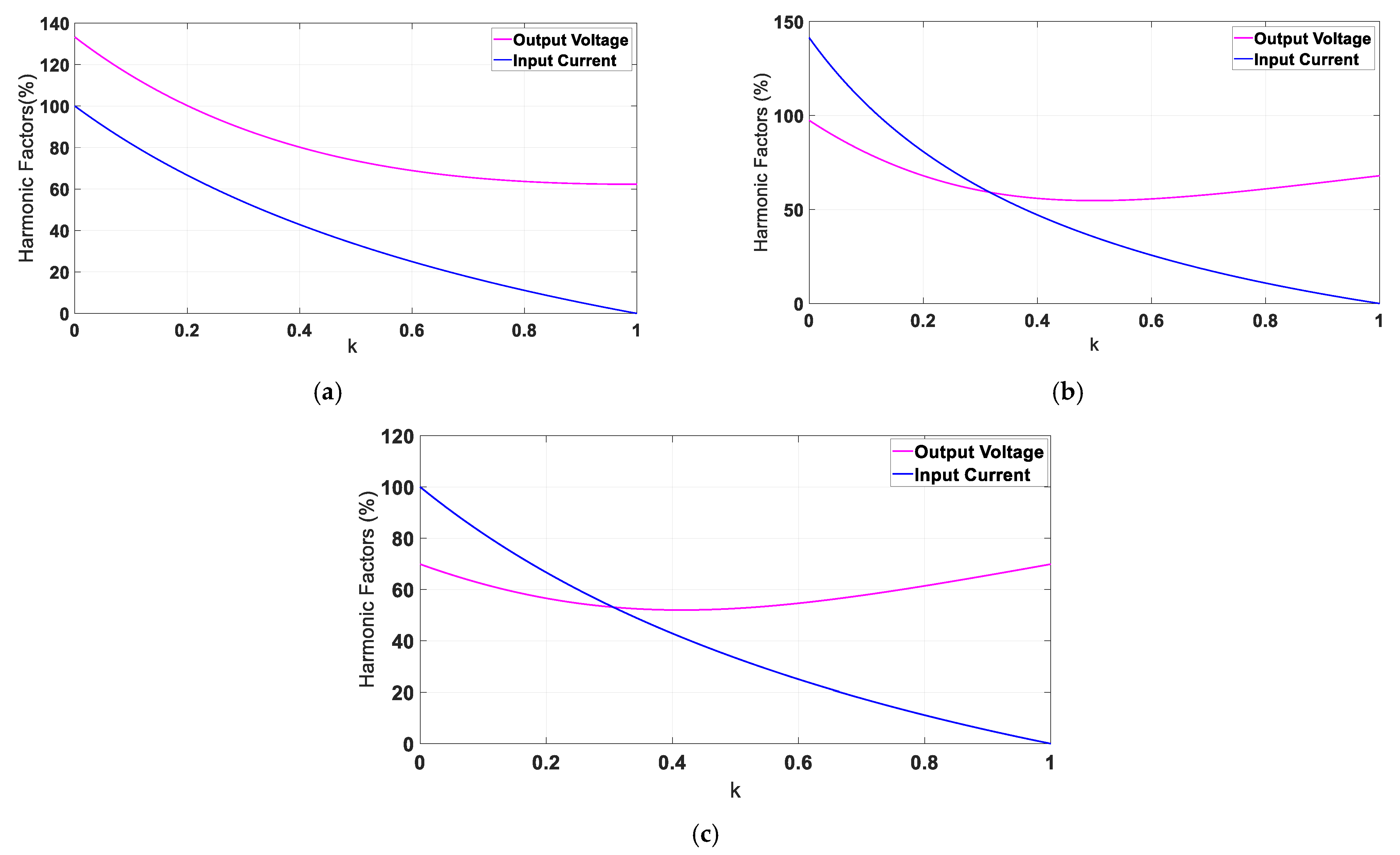
k) of some selected output pulses. So, variations in the harmonics factor both for output voltage and input current are examined with respect to the magnitude scaling factor. The plots of
Figure 7 illustrate the variation of the harmonic factors with respect to ‘
k’.
The detailed examination of these figures illustrates that harmonic factors of the output voltage and input current for one half frequency operation are low for the value of
k = 1, as may be seen from
Figure 7a. That is the case where amplitudes of all output half cycles are the same, helping to keep the harmonic factors of the output voltage and input current to 62% and 0%, respectively. For this output frequency, it is not possible to control the power quality of the output voltage by regulating the voltage of the selected half cycles. The harmonic factor for the output voltage as described in
Figure 8a is nearly 74%, and this can be confirmed from the FFT plot in
Figure 9a. The pulse voltage regulation approach only improves the harmonic characteristics for one-third and one-fourth output frequency. For these outputs, the harmonic factors of the output voltage are low for the value of
k = 0.5, as can be seen from
Figure 7b,c. However, the rate of decrement in the harmonic factors of the output voltage is low compared to the rate of rise in the harmonic factor of the input current once the value of magnitude scaling factor of the some selected half cycles of the output voltage is decreased from 1 to 0.5. In this situation, the harmonic factors of the input current are much improved once the value of
k is approaching unity.
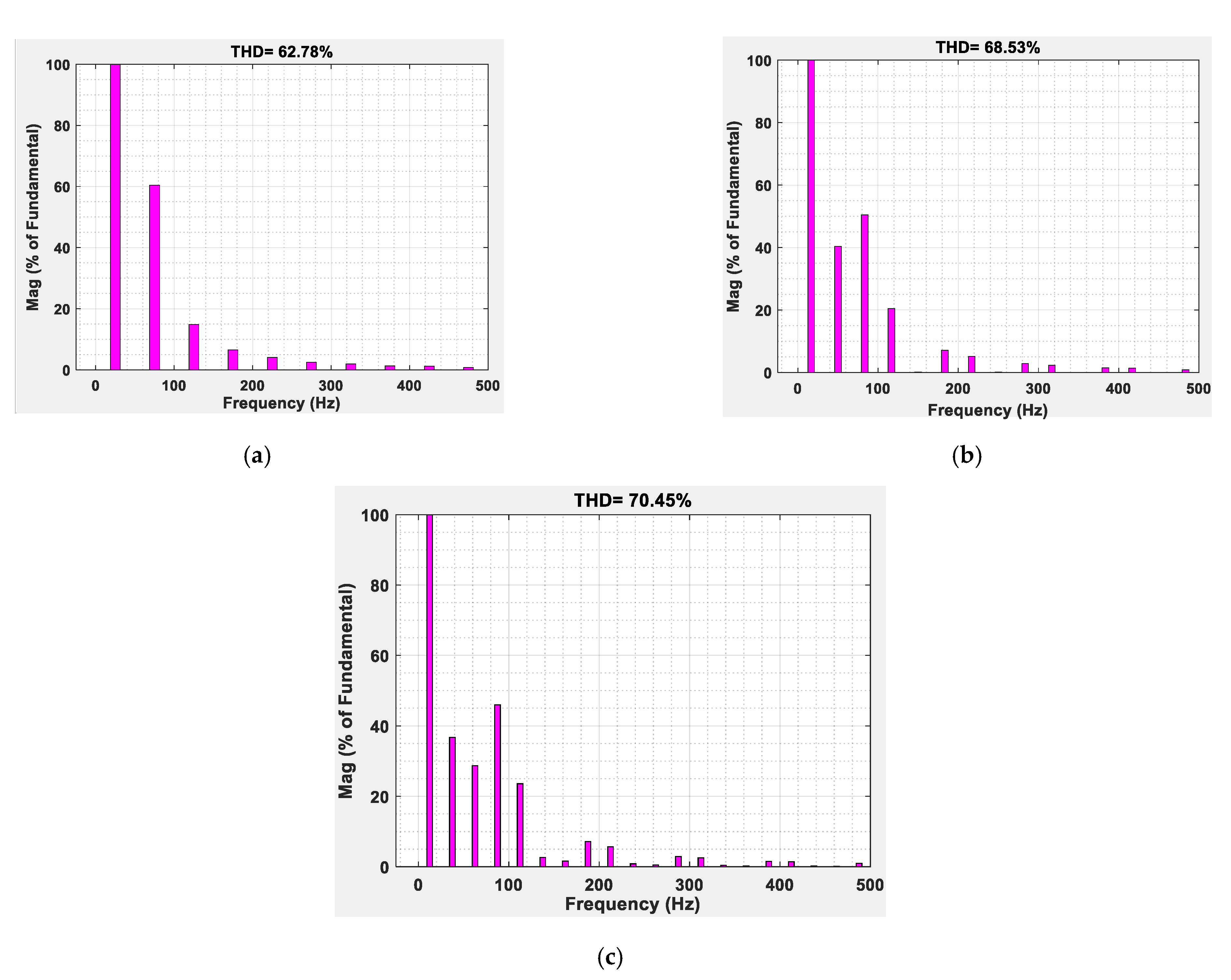
Figure 8 and
Figure 9, respectively, illustrate the output voltage and their spectral information for various output frequencies. Here, the harmonic characteristics of the output voltage are tried to improve by setting the value of
k = 0.5. This setting eliminates and lowers the source frequency harmonics from the output voltage for one-third and one-fourth output frequency, as may be found from the spectrum plot of
Figure 9b,c respectively. However, this value of ‘
k’ generates the line frequency harmonic (50 Hz) to approximately 40% of the fundamental component (25 Hz). There is also an increase in the amplitude of the other low-frequency harmonics which can be seen in
Figure 9a.
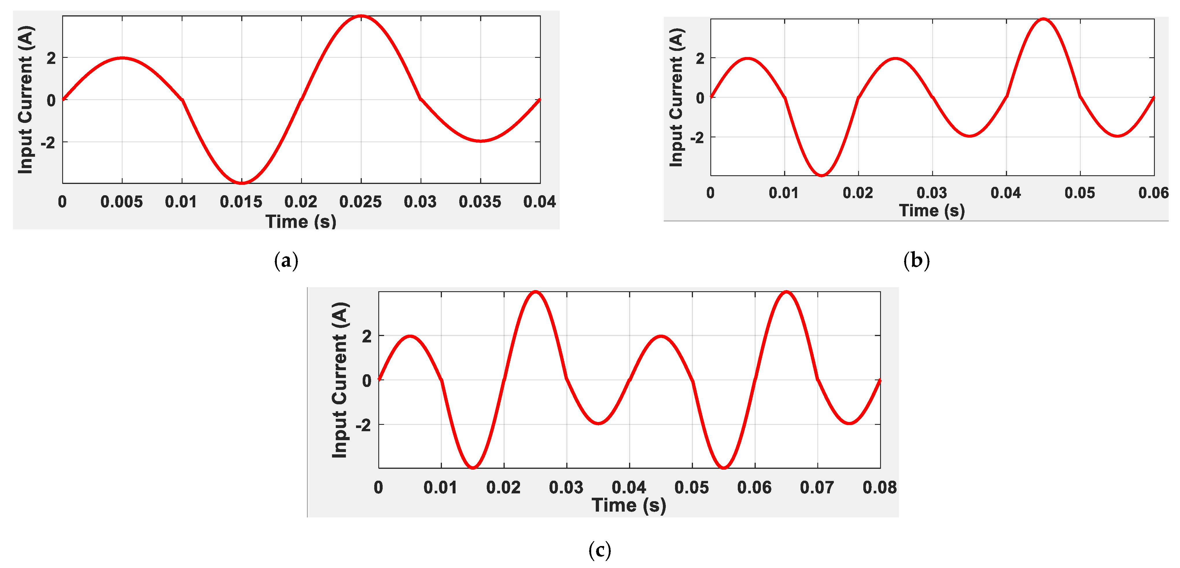
The 50% voltage amplitude adjustment in the selected half cycles of the output voltage deviates the sinusoidal characteristics of the input currents. The peak amplitude of all half cycles of the input currents, as shown in
Figure 10, is unequal. Once there is a low peak output voltage, it results in low peaks in the output and input currents. This change in the peak values of the input currents generates low-frequency harmonics shown in the FFT spectral plots of
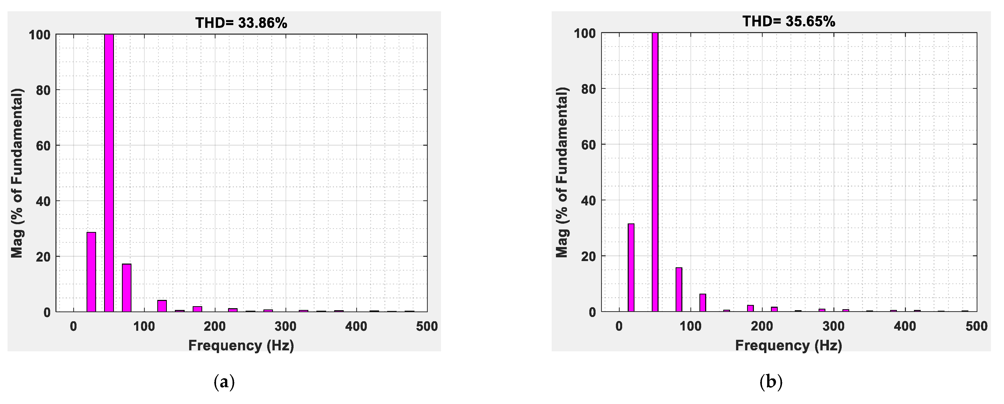
Figure 11.
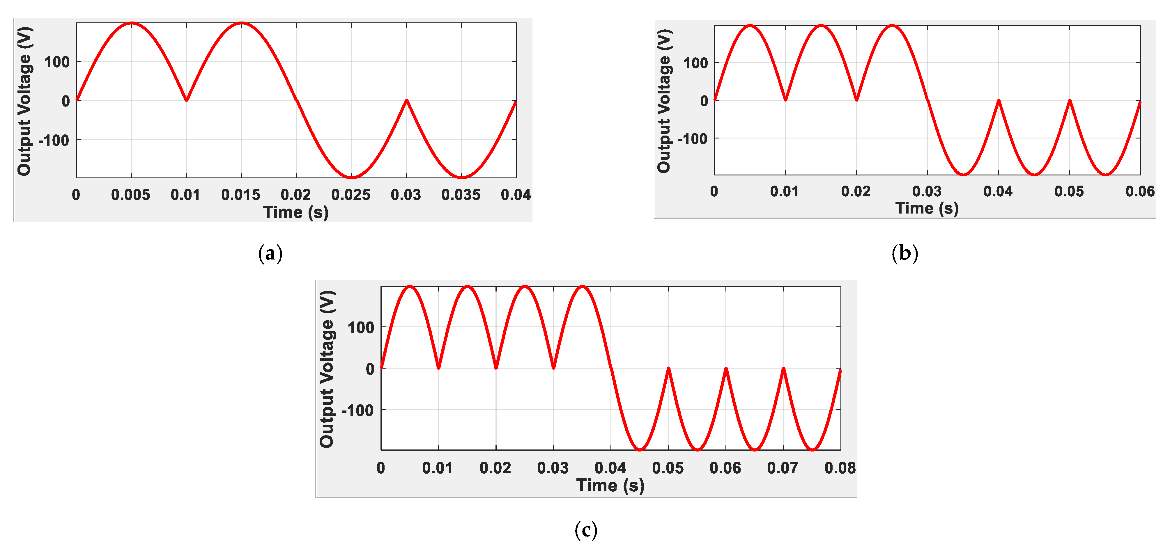
There are two prominent harmonics in the spectrum of these currents. The harmonics present at 25 Hz and 75 Hz frequencies have their amplitude at approximately 30% and 18% of the fundamental component (50 Hz). They are responsible for their harmonic factor of 35%. In summary, it is concluded that a 15% to 20% improvement in the harmonic factor of the output voltage results in an increase of 30% to 35% in the harmonic factor of the input current. There is no way to improve the power quality of the output voltage through the pulse voltage adjustment approach for the output frequency, which is one-half the input frequency. The plot of the output voltage without pulse adjustment approach for previously addressed three output frequencies and their corresponding FFT plots are illustrated in
Figure 12 and
Figure 13, respectively.
The investigation of these FFT results shows that although there is a slight increase in the harmonic factor of the output voltage, this approach helps retain the sinusoidal characteristics in the input currents (as described in
Figure 14).
4. Verification with Practical Results
The real results are always considered to be more authenticated in power conversion based on the switching behavior of solid-state devices. The results contain the practical constraints that are normally ignored in numerical calculation and simulation modeling. The practical test circuit reported in [
22] is used to validate the simulated and numerically obtained results as this topology is simple to realize. For this purpose, the peak value of the input voltage is taken at approximately 65 V with a supply frequency of 50 Hz.
In this regard,
Figure 15a shows the 25 Hz frequency output voltage with respect to its spectral plot. In this output, the amplitudes of the first and fourth half cycles are 50% of the amplitudes of the second and third half cycles. The FFT spectrum of output voltage indicates that the 75 Hz frequency harmonic has comparable amplitude (60%) with respect to the required 25 Hz component. This sort of output has a high harmonic factor of approximately 72%. The variation in the amplitude of the half cycles of the output voltage also varies the amplitude of the input current half cycles. It is clear for
Figure 15b that the first and fourth half cycles of the input current have 50% more amplitude than that of its second and third half cycles. The spectrum of
Figure 15b of input current indicates the generation of 25 Hz and 75 Hz harmonics responsible for a high value of its harmonic factor as their amplitudes are nearly 30% and 18% of the fundamental component (50 Hz), respectively. These input current harmonics increase the harmonic factor to nearly 34%. This investigation concludes that there is no improvement in the power quality for the output frequency which is one-half of the input frequency.
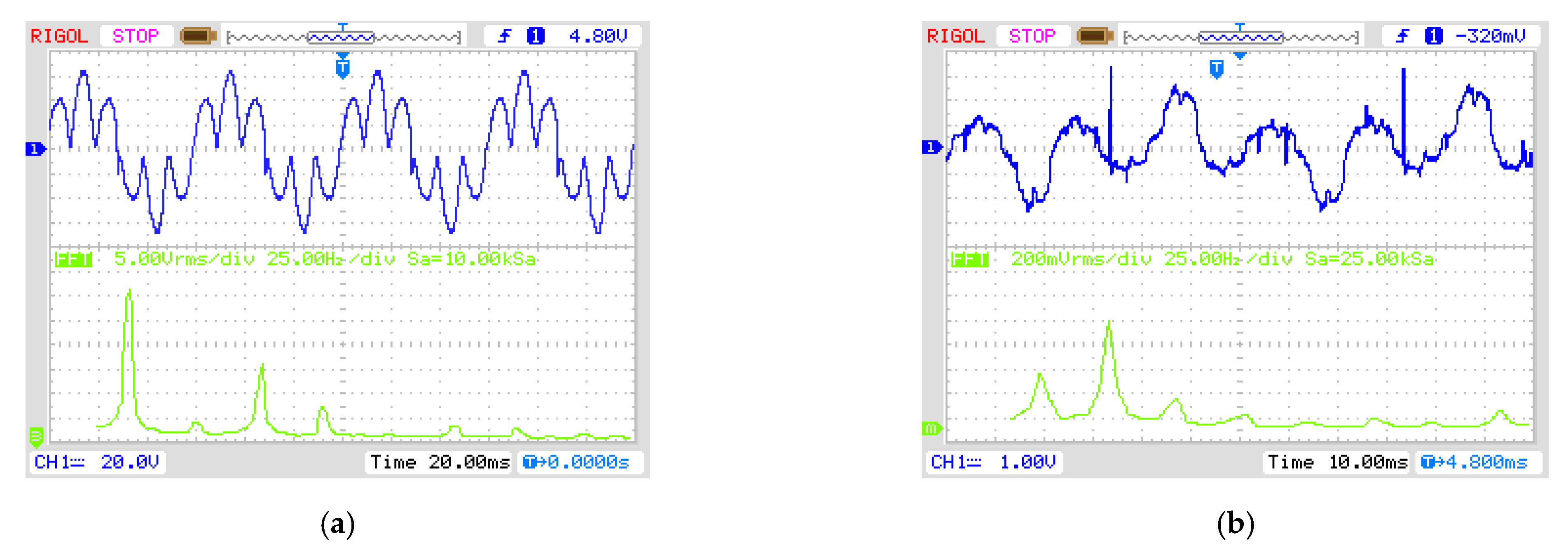
Some improvement in the power quality of the output voltage for the frequency where it is one-third of the input frequency is observed. To support this, the waveform of such output along with FFT is depicted in
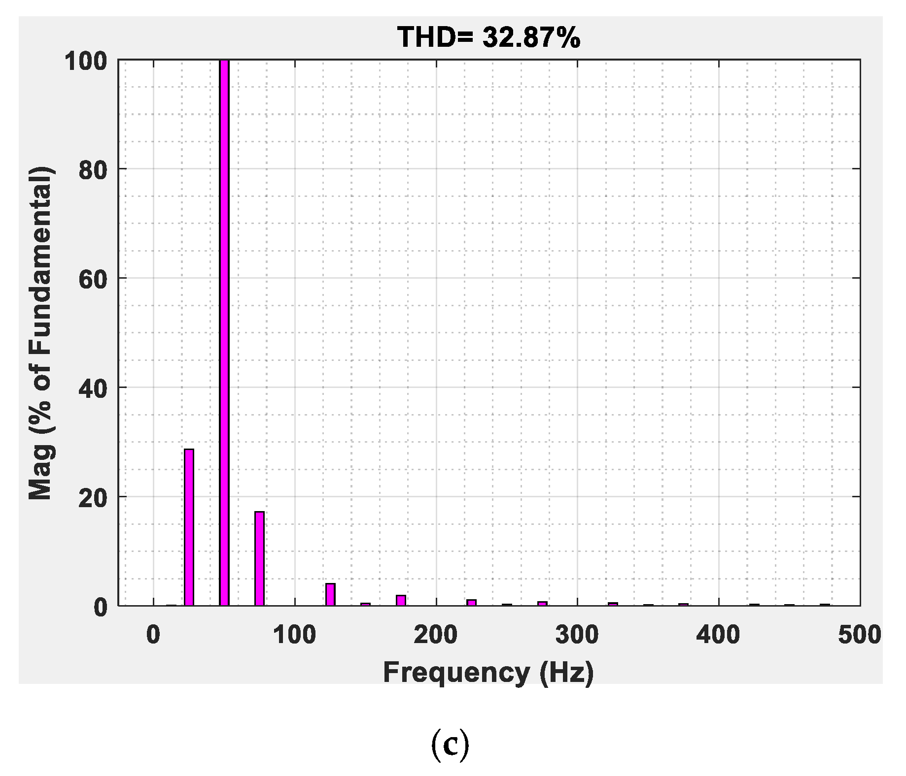
Figure 16a. In this waveform, there are six pulses in the output, and the amplitude of the first, third, fourth, and sixth are 50% more than that of pulse number second and fifth. This regulation in output pulse regulation results in eliminating the prominent voltage harmonic component existing at 50 Hz frequency. Its magnitude is one-third of the output voltage required component (50/3 Hz). This can be seen in the spectrum of the output voltage as illustrated in the FFT information of
Figure 16a. The voltage variation in the output pulses is also reflected in the input current in the form of unequal magnitude of the half cycles as shown in
Figure 16b. Here, the peak amplitude of the second and fifth half cycles of the input current is double that of the remaining half cycles. It can be seen from the FFT spectrum of the input current that with the fundamental component (50 Hz), there are some comparable low-frequency harmonics (25 and 75 Hz) that lead to a high value of the harmonic factor.
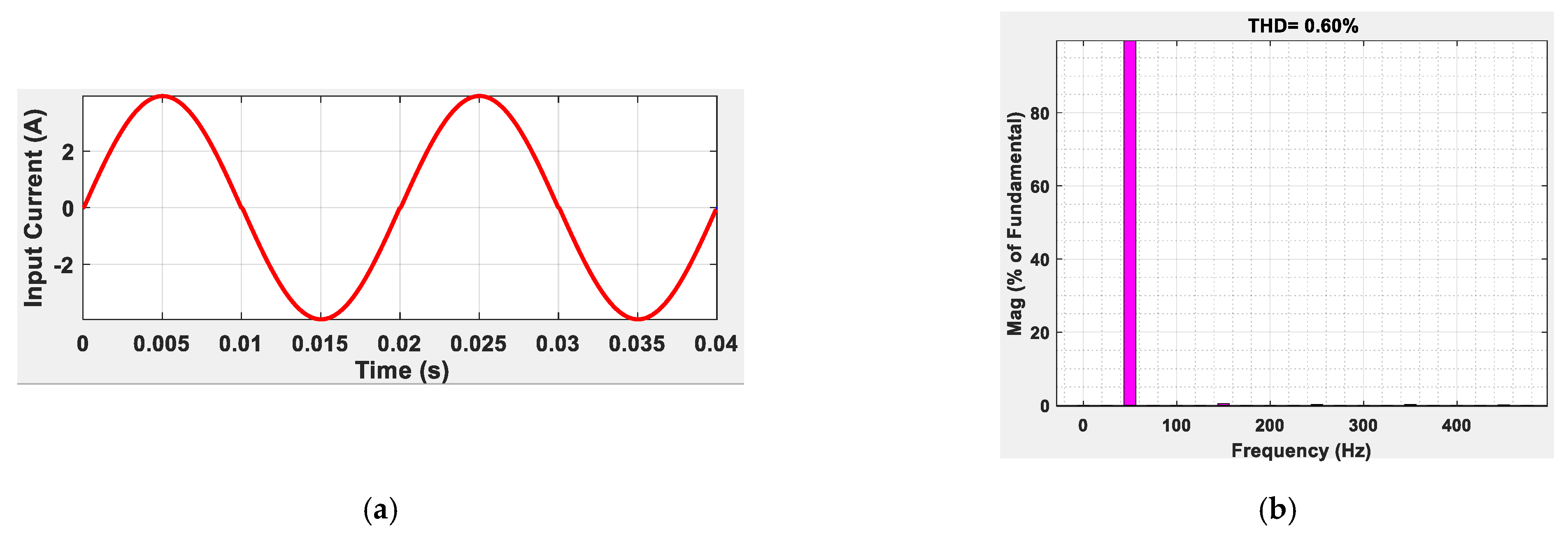
The power quality improvement of the input current for the pulse non-adjustment approach is described in
Figure 17. FFT spectrum of the output voltage for one-half and the one-third output frequency is illustrated in
Figure 17a,b. It is clearly shown that there is improvement in the harmonic profile of the output voltage for one-half frequency as the 50 Hz harmonic component has been successfully removed. The magnitude of the low-frequency harmonics for the one-third output frequency voltage slightly increases, raising its harmonics factor from 55% to 68%. However, the power quality indexes of the input current for the frequencies mentioned above are approaching their ideal value. The pulse non-regulated topology is very simple to realize, and its input current quality is inherently improved as its flow is continuous.


 ,
, 


