
Reconfiguration of a Bus Chassis Module Using the Digital Expression for Connectivity between Module Interfaces

Abstract
:Featured Application
Abstract
1. Introduction
2. Materials and Methods: Construction of the Digital Expression Model for the Bus Chassis Module Interface
2.1. Characterization of the Module Interface Geometry Information
2.2. Construction of a Digital Expression Model of the Module Interface
3. Criteria for Assessing the Interface Connectivity and the Reconfiguration of the Module
3.1. Assessment of the Interface Connectivity
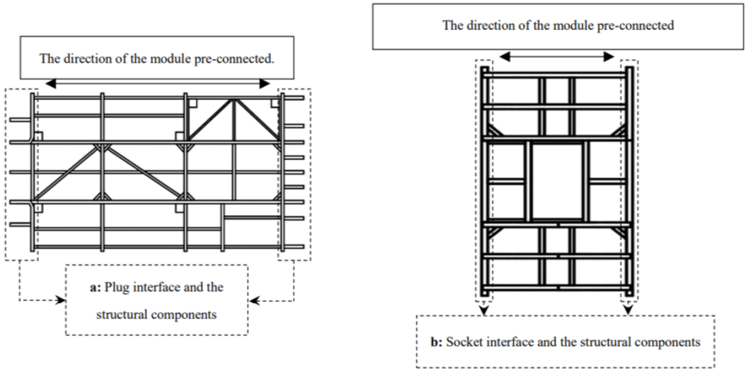
- The interface types of the two pre-connected modules are different. The interface type of the pre-connected module is determined according to the layout direction of the interface of the structural components. For good complementarity and compatibility, the interface type of the two pre-connected modules needs to be different.
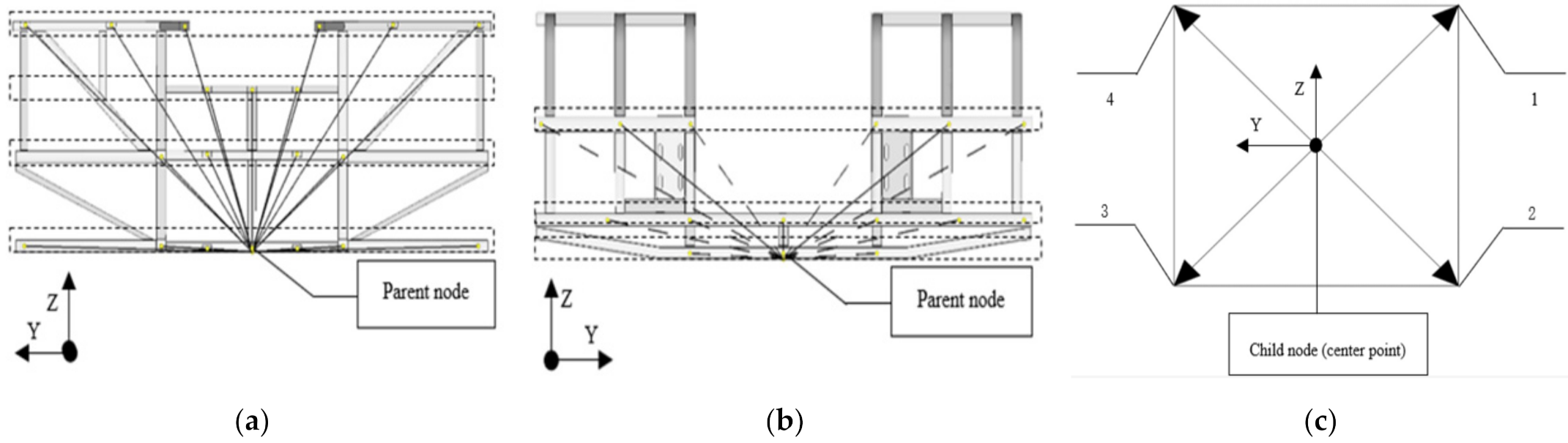
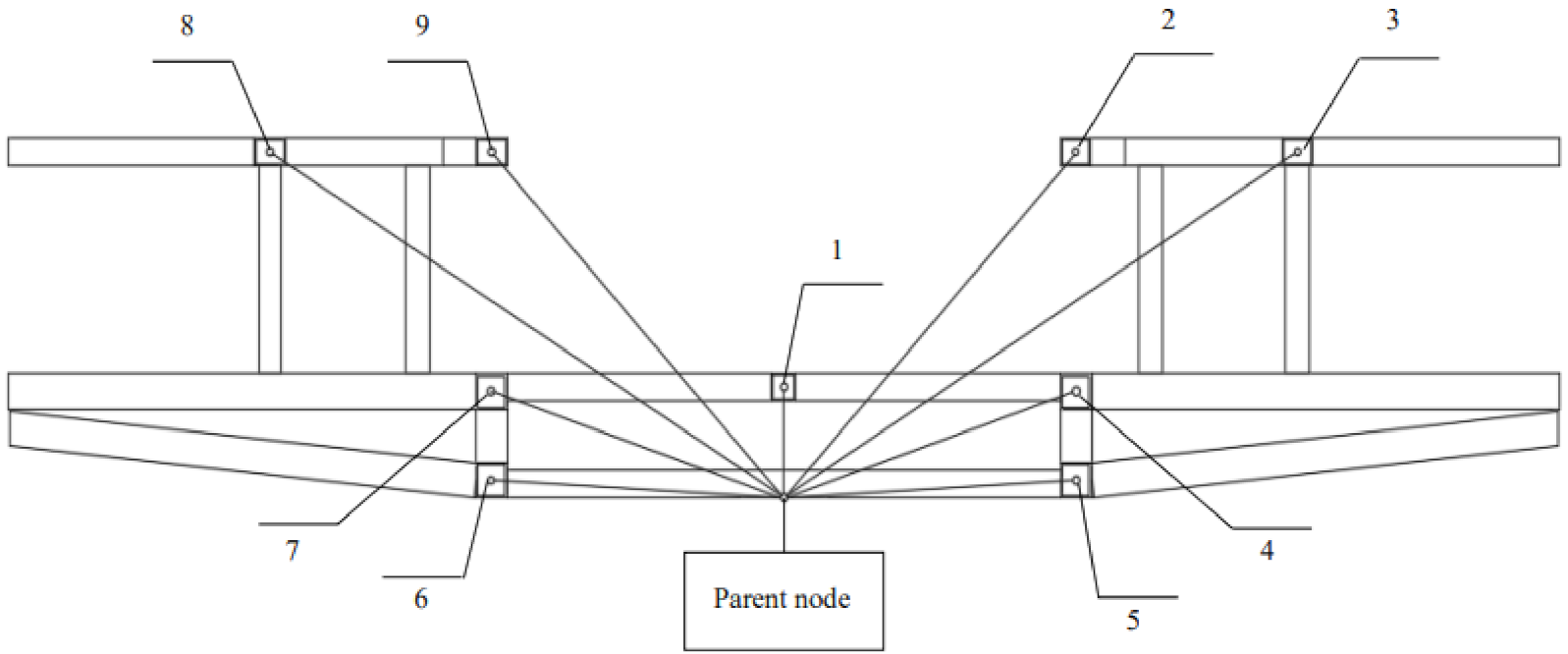
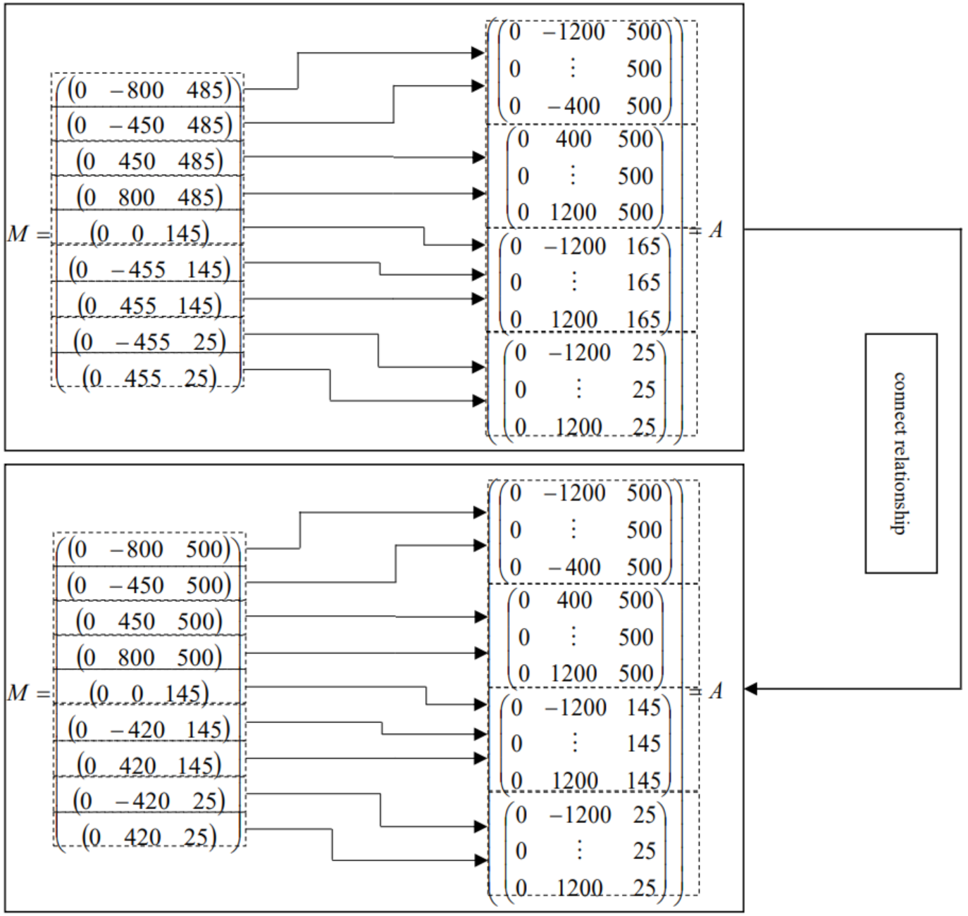
- The interface node network fully overlaps. Taking the parent node of the plug interface as a starting point, the pre-connected module’s node network of the two interfaces need to fully overlap. The digital expression for the full overlap condition reflects the first parent and child relationship (i.e., the parent and child relationship between the location matrix M and the location matrix A). This means the location coordinates of the corresponding nodes of the pre-connected structural components of the plug interface are all within the acceptance scope of the socket interface, as shown in Figure 5a,b.
- 3.
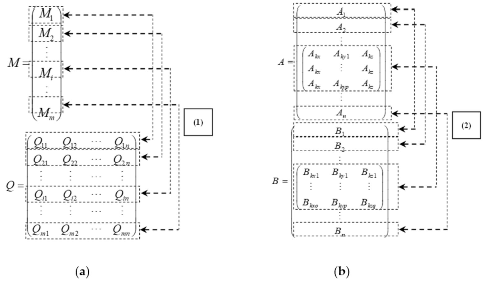
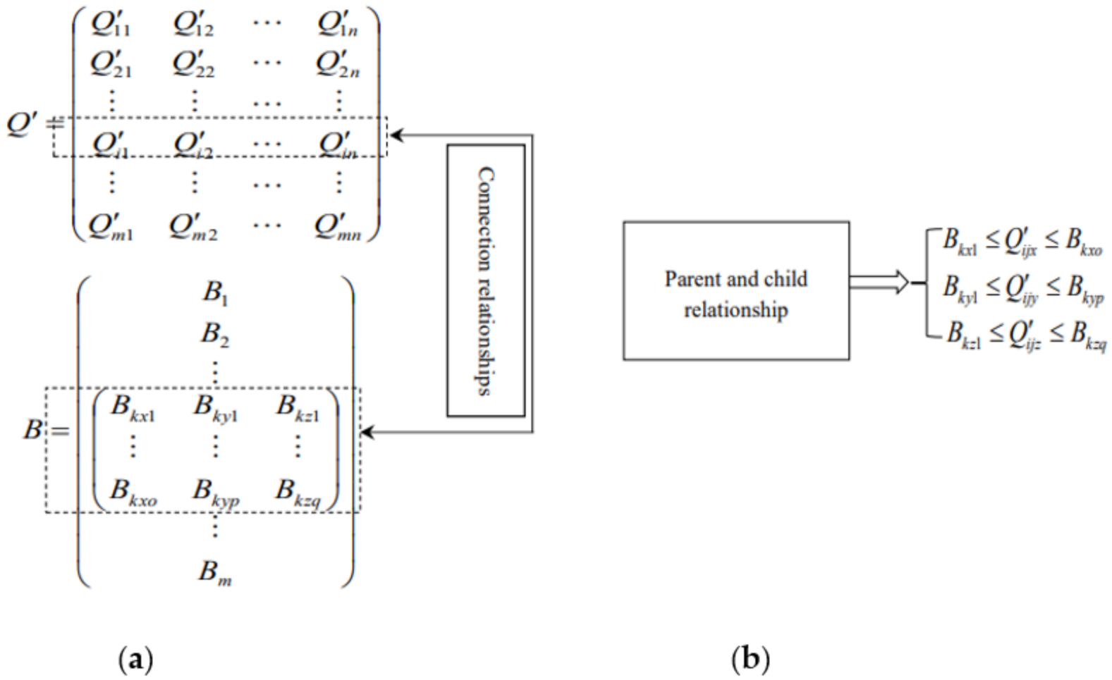
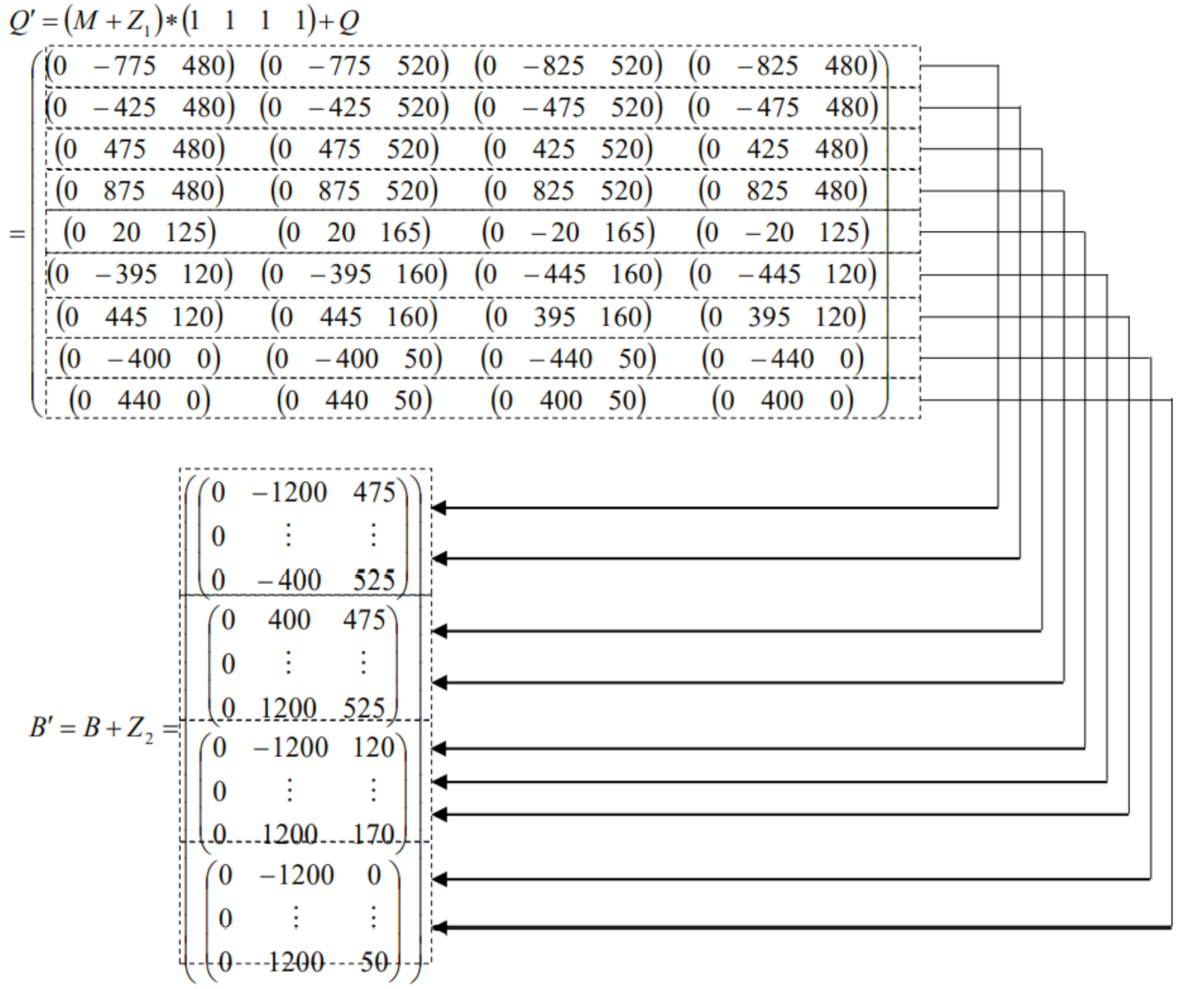
- The connection sections of the pre-connected structural components are matched. Based on the full overlap of the module interfaces, another condition is to satisfy the matching requirements of the shape and size of the connection section. With the digital expression of the interface, the condition reflects the second aspect of the parent and child relationship (i.e., the parent and child relationship between the connection section characterization matrix Q′ of the plug interface and the acceptance range matrix B of the socket interface). This means that all the feature points on the connection section of the pre-connected structural components of the plug interface are within the acceptance scope of the pre-connected structural components of the socket interface, as shown in Figure 6a,b.
3.2. Module Reconfiguration Using the Criteria
- Reconfiguration of the interface type: Either interface type is to be reconfigured. For the plug interface type, it can be changed by adding structural components that are perpendicular to the pre-connected direction of the module. The socket interface can be changed in two ways. One way is to add pre-connected structural components that are parallel to the pre-connected direction of the module. The other way is to remove the corresponding pre-connectedstructural components. The former may change the total length of the module, while the latter does not.
- Reconfiguration of the position of the pre-connected structural components: In order to achieve the connectivity between the two interfaces, both node networks need to fully overlap (i.e., the location of the interface pre-connected structural components can meet the matching relationship). In the real situation, some of the pre-connected structural components are adjustable and some are non-adjustable. In the process of translation of the node network, first, the non-adjustable structural components need to fully overlap. Thereafter, the position of the adjustable structural components are moved within a certain range. This proceeds until the ends of the interface node network of the two pre-connected module fully overlap.
- Reconfiguration of the connection section of the pre-connected structural components: In order to satisfy the different types of module interfaces and the full overlap of the interface node network, it is also necessary to meet the matching relationship for each pre-connected structural component. This means that the feature points of each of the pre-connected structural components of the plug interface are within the acceptable scope of the socket interface. There are two ways to reconfigure the connection section for pre-connection of structural components. One way is to reconfigure the shape and size of the pre-connected structural components of the plug interface. This changes the relative coordinates of the corresponding feature points. The other way is to reconfigure the shape and size of the socket interface, which changes the accepted range. This is done until the ends of all the connection sections of the pre-connected structural components meet the requirements of the connection-matching relationship.
4. Reconfiguration of the Bus Chassis Module
- Retrieve the module: Analyze the user needs and retrieve the appropriate modules that meet these requirements from the module database.
- Check and reconfigure the module interface: The module interface is checked to determine if the two pre-connected modules satisfy the interface-type conditions. If the two module interface types are the same, it is necessary to reconfigure one of them.
- Retrieving or constructing the digital expression model of the pre-connected module interfaces: The digital expression model of the plug interface includes the location matrix M and the relative characterization matrix Q of the connection section. The digital expression model of the socket interface includes the location matrix A and the acceptable range matrix B.
- Matching and reconfiguration of the position of the pre-connected structural components of the interface: The connection matching of the position of the interface structural components is evaluated by the parent and child relationship between the location matrix M of the plug interface and the location matrix A of the socket interface. Adjustable components are reconfigured to achieve connectivity for full overlap of the interface node network.
- Construction and operation of the process matrix: Once the module is reconfigured during the connection-matching process, the reconfiguration process matrix Z is constructed. Then, the reconfiguring of the module, the position, or the section size of a component changes, and the change is written into the matrix Z in the form of coordinates, thus forming the reconstruction process matrix. The characterization matrix Q′ of the connection section of the plug interface and the acceptable range matrix B′ of the socket interface are solved thereafter.
- Matching and reconfiguration of the connection section of the pre-connected structural components: Based on step (5), matching of the connection section of the interface structural components is evaluated by the parent and child relationship between the characterization matrix Q′ for the connection section of the plug interface and the acceptable range matrix B′ of the socket interface. Meanwhile, the connection section of the adjustable structural components is reconfigured to meet the requirements of the matching relationship.
- Completion of the module reconfiguration: The connection-matching relationship of the module interface is checked, and then the pre-connected module is reconfigured based on the calculation results. The module can be fine-tuned according to the actual engineering needs, until the final design of the module is completed.
5. Case Study
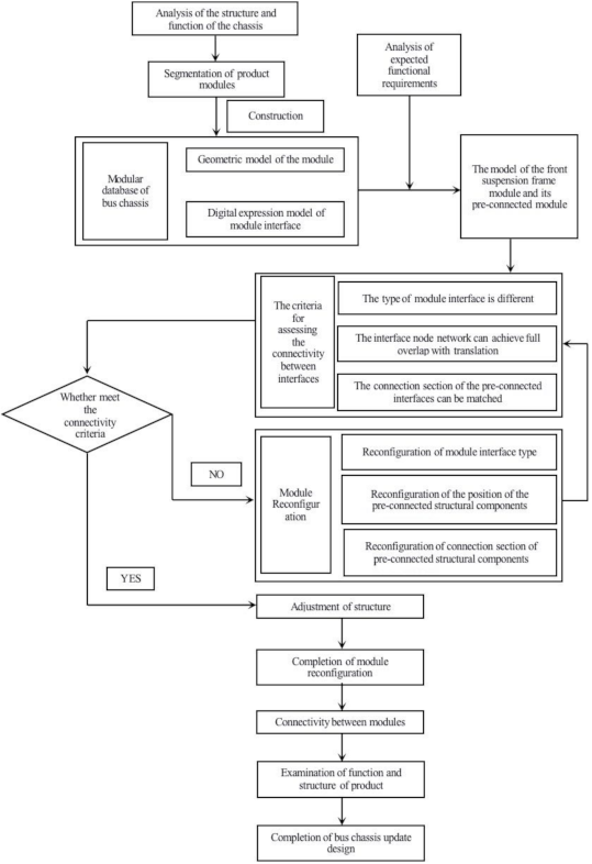
5.1. The Modular Design Process for the Bus Chassis
5.2. Construction of the Digital Expression Model of the Pre-Connected Module Interface
5.3. Confirmation of the Matching Relationship of the Module Connection and Reconfiguration Based on the Connectivity Criteria
- Retrieve the front suspension frame module: The user’s needs are analyzed, and the front suspension frame module that meets the functions and performance requirements is retrieved from the module database.
- Check and reconfigure the design of the type of module interface: The type of the interface of the front suspension frame module and the interface of the middle frame module is checked. Analysis shows that the rear interface of the front suspension frame module is a socket interface, while the front interface of the middle module is a plug interface. This satisfies the first criterion of the connection between module interfaces (i.e., the type of the two pre-connected interfaces must be different). Therefore, there is no need to reconfigure this module interface.
- Construction of the digital expression model of module interface: The digital expression model of the rear interface of the front suspension frame module and the front interface of the middle front module is constructed. For the middle module, the model includes the interface location matrix M and the relative representation matrix Q for the connection section. For the front suspension module, the model includes the interface location matrix A and the acceptable range matrix B.
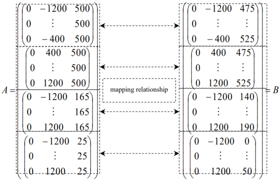
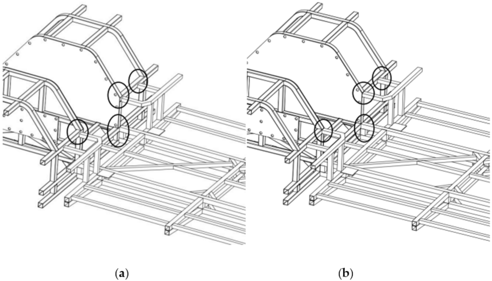
- Matching and reconfiguring the position of the pre-connected structural components of the module interface: The second criterion, indicating that the two modules can be connected, is used (i.e., whether the node network of the module interface can overlap fully with the translation). The interface location matrix M of the middle frame module and the interface location matrix A of the front suspension framework module are obtained from the digital expression model. Thereafter, the connection matching relationship between the pre-connected structural components is assessed based on the relationship between the matrices M and A. Finally, some adjustable structural components are reconfigured to meet the requirements of the connection-matching modules. The design results are shown in Figure 13.
- Construction and operation of the process matrix: The front suspension frame module and the middle frame module have been reconfigured in step (4). Subsequently, the reconfiguration process matrices Z1 and Z2 of the two modules are constructed according to the results of the design, respectively, as shown in Equation (6). Z1 is the process matrix of the middle frame module and Z2 is the process matrix of the front suspension frame module.
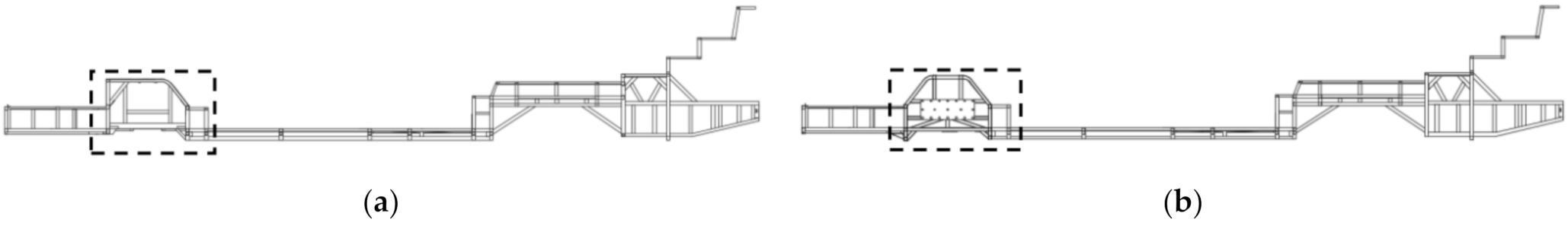
- Matching and reconfiguring the design of the connection section of the pre-connected structural components: Using the reconfiguration results in step (5), the connection section characterization matrix Q′ of the middle frame module interface and the acceptance range matrix B′ of the front suspension frame interface are calculated. The third criterion for module interface connectivity is then evaluated (i.e., the matching relation of the connection section of the pre-connected structural components), as shown in Figure 14. The criterion is digitally expressed as the parent and child relationship between the matrix Q′ and the matrix B′. Results show that the connection section of the pre-connected component meets the requirement for the connection-matching relationship. Therefore, it is not necessary to reconfigure the connection section further.
- Completion of the reconfiguration of the module: The connection-matching relationship of the module interface is checked. Thereafter, reconfiguration of the modules is completed and the connectivity between the modules is established, according to the above calculation results.
5.4. Updated and Improved Design of the Bus Chassis
6. Conclusions
- The digital expression of the chassis module interface provides criteria for assessing the connectivity between modules. Connectivity between modules can be identified quickly and accurately through the parent and child relationship using the matrices of the digital expression for the interface. This greatly improves the efficiency of the modular design. At the same time, the connection criterion perfects the digital expression method of the module interface and improves the implementation of the digital expression method.
- A reconfiguration method for modules, based on the digital expression of the module interface, was proposed and implemented for a real-world case bus chassis. This method is oriented to the connectivity between modules. It relies on the guidance of their reconfiguration of the module through the digital operation, step by step. This improves the versatility and interchangeability of the module. The method could be applied in the future to the reconfiguration of a product module with a similar truss structure.
- In the actual process of product design, the module reconfiguration method based on the interface digital expression method can quickly determine whether the original module can be borrowed and applied through the numerical relationship of the interface matrix, and show module reconfiguration through the numerical relationship. The borrowing or reconfiguration of original modules greatly reduces the development cost of new modules and products and plays an important role in helping enterprises to implement platform and diversified products.
- In addition, in this study, the specific connection methods for the interface in the manufacturing process, such as the welding process for the bus chassis frame and the welding strength, were not discussed, and further research is needed in the future.
- The strength and stiffness of bus chassis modules should be investigated to identify the effect of reconfiguration on mechanical behavior.
- The connections between hybrid material linkages should be further investigated, as the welding parameters and the connection techniques may be different.
- The implementation of this method in manufacturing requires a comprehensive study, including consideration of the assembly sequence and associated equipment.
Author Contributions
Funding
Institutional Review Board Statement
Informed Consent Statement
Data Availability Statement
Conflicts of Interest
References
- Boulanger, A.G.; Chu, A.C.; Maxx, S.; Waltz, D.L. Vehicle Electrification: Status and Issues. Proc. IEEE 2011, 99, 1116–1138. [Google Scholar] [CrossRef] [Green Version]
- Mahmoud, M.; Garnett, R.; Ferguson, M.; Kanaroglou, P. Electric buses: A review of alternative powertrains. Renew. Sustain. Energy Rev. 2016, 62, 673–684. [Google Scholar] [CrossRef]
- Dreier, D.; Silveira, S.; Khatiwada, D.; Fonseca, K.V.O.; Nieweglowski, R.; Schepanski, R. Well-to-Wheel analysis of fossil energy use and greenhouse gas emissions for conventional, hybrid-electric and plug-in hybrid-electric city buses in the BRT system in Curitiba, Brazil. Transp. Res. Part D Transp. Environ. 2018, 58, 122–138. [Google Scholar] [CrossRef]
- Du, J.; Ouyang, M.; Chen, J. Prospects for Chinese electric vehicle technologies in 2016–2020: Ambition and rationality. Energy 2017, 120, 584–596. [Google Scholar] [CrossRef]
- Napper, R. Modular route bus design—A method of meeting transport operation and vehicle manufacturing requirements. Transp. Res. Part C Emerg. Technol. 2014, 38, 56–72. [Google Scholar] [CrossRef]
- Millo, F.; Rolando, L.; Fuso, R.; Zhao, J. Development of a New Hybrid Bus for Urban Public Transportation. Appl. Energy 2015, 157, 583–594. [Google Scholar] [CrossRef]
- Leng, J.; Liu, Q.; Ye, S.; Jing, J.; Wang, Y.; Zhang, C.; Zhang, D.; Chen, X. Digital twin-driven rapid reconfiguration of the automated manufacturing system via an open architecture model. Robot. Comput. Manuf. 2020, 63, 101895. [Google Scholar] [CrossRef]
- Baldwin, C.Y.; Clark, K.B. Managing in an age of modularity. Harv. Bus. Rev. 1997, 75, 84–93. [Google Scholar]
- Piran, F.; Lacerda, D.; Camargo, L.F.R.; Viero, C.F.; Dresch, A.; Cauchick-Miguel, P.A. Product modularization and effects on efficiency: An analysis of a bus manufacturer using data envelopment analysis (DEA). Int. J. Prod. Econ. 2016, 182, 1–13. [Google Scholar] [CrossRef]
- Ulrich, K. Fundamentals of Product Modularity. In Management of Design: Engineering and Management Perspectives; Dasu, S., Eastman, C., Eds.; Springer: Dordrecht, The Netherlands, 1994; pp. 219–231. [Google Scholar]
- Alizon, F.; Khadke, K.; Thevenot, H.J.; Gershenson, J.K.; Marion, T.J.; Shooter, S.B.; Simpson, T.W. Frameworks for Product Family Design and Development. Concurr. Eng. 2007, 15, 187–199. [Google Scholar] [CrossRef]
- Bruun, H.P.L.; Mortensen, N.H.; Harlou, U. Interface diagram: Design tool for supporting the development of modularity in complex product systems. Concurr. Eng. 2013, 22, 62–76. [Google Scholar] [CrossRef]
- Salvador, F.; Forza, C.; Rungtusanatham, M. Modularity, product variety, production volume, and component sourcing: Theorizing beyond generic prescriptions. J. Oper. Manag. 2002, 20, 549–575. [Google Scholar] [CrossRef]
- Barbosa, L.M.; Lacerda, D.; Piran, F.; Dresch, A. Exploratory analysis of the variables prevailing on the effects of product modularization on production volume and efficiency. Int. J. Prod. Econ. 2017, 193, 677–690. [Google Scholar] [CrossRef]
- Pires, S.R. Managerial implications of the modular consortium model in a Brazilian automotive plant. Int. J. Oper. Prod. Manag. 1998, 18, 221–232. [Google Scholar] [CrossRef]
- ISE Corporation. 2007. Available online: http://www.isecorp.com (accessed on 20 December 2021).
- Habib, T.; Kristiansen, J.N.; Rana, M.B.; Ritala, P. Revisiting the role of modular innovation in technological radicalness and architectural change of products: The case of Tesla X and Roomba. Technovation 2020, 98, 102163. [Google Scholar] [CrossRef]
- Schuh, G.; Arnoscht, J.; Rudolf, S.; Korthals, K. Modular Chassis Product Platform Considering Variable Quantities for an Economical Electric Vehicle Production; Springer: Berlin/Heidelberg, Germany, 2013; pp. 73–82. [Google Scholar]
- Peng, Q.; Liu, S.; Robinson, M.; Han, F.-G.; Matsika, E. A digital expression method for the module interface in a practical bus chassis modular design and case history. Concurr. Eng. 2018, 26, 355–366. [Google Scholar] [CrossRef] [Green Version]
- Tao, F.; Cheng, J.; Qi, Q.; Zhang, M.; Zhang, H.; Sui, F. Digital twin-driven product design, manufacturing and service with big data. Int. J. Adv. Manuf. Technol. 2017, 94, 3563–3576. [Google Scholar] [CrossRef]
- Rassolkin, A.; Vaimann, T.; Kallaste, A.; Kuts, V. Digital twin for propulsion drive of autonomous electric vehicle. In Proceedings of the 2019 IEEE 60th International Scientific Conference on Power and Electrical Engineering of Riga Technical University (RTUCON), Riga, Latvia, 7–9 October 2019. [Google Scholar] [CrossRef]
- Bhatti, G.; Mohan, H.; Singh, R.R. Towards the future of smart electric vehicles: Digital twin technology. Renew. Sustain. Energy Rev. 2021, 141, 110801. [Google Scholar] [CrossRef]
- Koren, Y.; Hu, S.; Gu, P.; Shpitalni, M. Open-architecture products. CIRP Ann. 2013, 62, 719–729. [Google Scholar] [CrossRef]
- Baldwin, C.Y.; Clark, K.B. Design Rules Volume I: The Power of Modularity; MIT Press: Cambridge, MA, USA, 2000; Volume 1. [Google Scholar]
- Ulrich, K. The role of product architecture in the manufacturing firm. Res. Policy 1995, 24, 419–440. [Google Scholar] [CrossRef] [Green Version]
- Chen, K.-M.; Liu, R.-J. Interface strategies in modular product innovation. Technovation 2005, 25, 771–782. [Google Scholar] [CrossRef]
- Cabigiosu, A.; Zirpoli, F.; Camuffo, A. Modularity, interfaces definition and the integration of external sources of innovation in the automotive industry. Res. Policy 2013, 42, 662–675. [Google Scholar] [CrossRef] [Green Version]
- Bonvoisin, J.; Halstenberg, F.; Buchert, T.; Stark, R. A systematic literature review on modular product design. J. Eng. Des. 2016, 27, 488–514. [Google Scholar] [CrossRef]
- Pereira, M.; Weingaertner, W.; Forcellini, F. Design Methodology for Reconfigurable Precision Systems Applied to a Sclerometer Development; Cirp-International Seminar on Manufacturing Systems: Florianopolis, Brazil, 2005. [Google Scholar]
- Hölttä, K.M.; Otto, K.N. Incorporating design effort complexity measures in product architectural design and assessment. Des. Stud. 2005, 26, 463–485. [Google Scholar] [CrossRef]
- Usha, K.; Upadhyaya, S. An interface complexity measure for component-based software systems. Int. J. Comput. Appl. 2011, 36, 46–52. [Google Scholar]
- Oh, K.; Kim, H.W.; Kim, D.; Lee, J.; Lee, J.; Hong, Y.S. Product Interface Design for Complexity Management in Assembly Systems. IEEE Access 2020, 8, 225491–225506. [Google Scholar] [CrossRef]
- Ulrich, K.T.; Eppinger, S.D. Product Design and Development; Tata McGraw-Hill Education: New York, NY, USA, 2003. [Google Scholar]
- Sinha, K.; de Weck, O.L. Structural Complexity Quantification for Engineered Complex Systems and Implications on System Architecture and Design. In Proceedings of the ASME 2013 International Design Engineering Technical Conferences and Computers and Information in Engineering Conference, Portland, OR, USA, 4–7 August 2013. [Google Scholar] [CrossRef] [Green Version]
- Sheard, S.A.; Mostashari, A. 7.3.1 A Complexity Typology for Systems Engineering. In Proceedings of the INCOSE International Symposium, Chicago, IL, USA, 12–15 July 2010; Wiley Online Library: Hoboken, NJ, USA, 2010; pp. 933–945. [Google Scholar]


| Node Number | Adjustable | Location of Child Node | Description of Pre-Connected Components | Relative Coordinates of Feature Points | ||||||
|---|---|---|---|---|---|---|---|---|---|---|
| x | y | z | ||||||||
| 1 | N | 0 | 0 | 145 | Square 40 × 40 | Number | ① | ② | ③ | ④ |
| Coordinate | (0, 20, −20) | (0, 20, 20) | (0, −20, 20) | (0, −20, −20) | ||||||
| 2 | Y | 0 | −450 | 485 | Rectangle 50 × 40 | Number | ① | ② | ③ | ④ |
| Coordinate | (0, 25, −20) | (0, 25, 20) | (0, −25, 20) | (0, −25, −20) | ||||||
| 3 | Y | 0 | −800 | 485 | Rectangle 50 × 40 | Number | ① | ② | ③ | ④ |
| Coordinate | (0, 25, −20) | (0, 25, 20) | (0, −25, 20) | (0, −25, −20) | ||||||
| 4 | N | 0 | −455 | 145 | Square 50 × 50 | Number | ① | ② | ③ | ④ |
| Coordinate | (0, 25, −25) | (0, 25, 25) | (0, −25, 25) | (0, −25, −25) | ||||||
| 5 | N | 0 | −455 | 25 | Square 50 × 50 | Number | ① | ② | ③ | ④ |
| Coordinate | (0, 25, −25) | (0, 25, 25) | (0, −25, 25) | (0, −25, −25) | ||||||
| 6 | N | 0 | 455 | 25 | Square 50 × 50 | Number | ① | ② | ③ | ④ |
| Coordinate | (0, 25, −25) | (0, 25, 25) | (0, −25, 25) | (0, −25, −25) | ||||||
| 7 | N | 0 | 455 | 145 | Square 50 × 50 | Number | ① | ② | ③ | ④ |
| Coordinate | (0, 25, −25) | (0, 25, 25) | (0, −25, 25) | (0, −25, −25) | ||||||
| 8 | Y | 0 | 800 | 485 | Rectangle 50 × 40 | Number | ① | ② | ③ | ④ |
| Coordinate | (0, 25, −20) | (0, 25, 20) | (0, −25, 20) | (0, −25, −20) | ||||||
| 9 | Y | 0 | 450 | 485 | Rectangle 50 × 40 | Number | ① | ② | ③ | ④ |
| Coordinate | (0, 25, −20) | (0, 25, 20) | (0, −25, 20) | (0, −25, −20) | ||||||
| Node Numbering | Layout Direction of Structural Component | Whether It Is Adjustable | Location of Structural Components | Relative Acceptable Range of Structural Components | |||||||
|---|---|---|---|---|---|---|---|---|---|---|---|
| y Direction | z Direction | x Direction | y Direction | z Direction | |||||||
| 1 | Parallel to the y direction | Y | N | 0 | −800 | 500 | Direction | y | z | ||
| Range value | −400 | 400 | −25 | 25 | |||||||
| 2 | Parallel to the y direction | Y | N | 0 | 800 | 500 | Direction | y | z | ||
| Range value | −400 | 400 | −25 | 25 | |||||||
| 3 | Parallel to the y direction | Y | Y | 0 | 0 | 165 | Direction | y | z | ||
| Range value | −1200 | 1200 | −25 | 25 | |||||||
| 4 | Parallel to the y direction | Y | Y | 0 | 0 | 25 | Direction | y | z | ||
| Range value | −1200 | 1200 | −25 | 25 | |||||||
Publisher’s Note: MDPI stays neutral with regard to jurisdictional claims in published maps and institutional affiliations. |
© 2022 by the authors. Licensee MDPI, Basel, Switzerland. This article is an open access article distributed under the terms and conditions of the Creative Commons Attribution (CC BY) license (https://creativecommons.org/licenses/by/4.0/).
Share and Cite
Peng, Q.; Meng, X.; Liu, S.; Han, F.; Robinson, M. Reconfiguration of a Bus Chassis Module Using the Digital Expression for Connectivity between Module Interfaces. Appl. Sci. 2022, 12, 3274. https://doi.org/10.3390/app12073274
Peng Q, Meng X, Liu S, Han F, Robinson M. Reconfiguration of a Bus Chassis Module Using the Digital Expression for Connectivity between Module Interfaces. Applied Sciences. 2022; 12(7):3274. https://doi.org/10.3390/app12073274
Chicago/Turabian StylePeng, Qian, Xiangchao Meng, Sheng Liu, Fenggang Han, and Mark Robinson. 2022. "Reconfiguration of a Bus Chassis Module Using the Digital Expression for Connectivity between Module Interfaces" Applied Sciences 12, no. 7: 3274. https://doi.org/10.3390/app12073274
APA StylePeng, Q., Meng, X., Liu, S., Han, F., & Robinson, M. (2022). Reconfiguration of a Bus Chassis Module Using the Digital Expression for Connectivity between Module Interfaces. Applied Sciences, 12(7), 3274. https://doi.org/10.3390/app12073274