Article

Reconfiguration of a Bus Chassis Module Using the Digital Expression for Connectivity between Module Interfaces

1
School of Mechanical and Automotive Engineering, Xiamen University of Technology, Xiamen 361024, China
2
Future Mobility Group, School of Engineering, Newcastle University, Newcastle NE1 7RU, UK
*
Author to whom correspondence should be addressed.
Appl. Sci. 2022, 12(7), 3274; https://doi.org/10.3390/app12073274
Submission received: 24 January 2022 / Revised: 14 March 2022 / Accepted: 21 March 2022 / Published: 23 March 2022

Abstract

:

Featured Application

This featured application can be implemented in the field of bus chassis design and manufacture to meet the customization of bus products, due to the diverse demands of bus operators.

Abstract

Modular design for a bus chassis is a practical solution to address different bus types and their differing powertrains. Physics interfaces are used to connect interacting subsystems in bus chassis modules. There are few studies focusing on the criteria for assessing interface connectivity, with significantly non-standard characteristics, between bus chassis modules. This study proposes criteria for assessing the interface connectivity in bus chassis modules in accordance with the digital expression of the module interface. Criteria for judging the compatibility of the connection between bus chassis modules are proposed and modular reconfiguration methods are provided, based on the criteria. Reconfiguration of the process matrix is constructed to indicate changes in position, shape, and size after the component is modified, based on the connectivity between modules. Finally, the proposed method is applied to the reconfiguration and replacement of the front suspension frame module of a bus chassis. The results demonstrated and proved the effectiveness of this method.

1. Introduction

As new energy powertrains merge into the vehicle industry, bus chassis were greatly modified compared to those of traditional engine powered vehicles [1,2]. In the typical model of body-on-chassis, a bus mounts diverse power sources on the chassis, such as the battery, hybrid power system, fuel cells, and a supercapacitor [3,4]. In addition, the variety of orders from various bus operators influence bus manufacturing, with operators specifying the configurations of each chassis, particularly in relation to battery capacities and motor types. These specifications are in accordance with their targeted operating routes and ranges, driving scenarios, and costs; hence, bus manufacturers face great challenges in terms of development costs and response cycle issues, considering the small volume, wide variety, and customization of bus products, due to the diverse demands of bus operators [5,6].
Highly frequent changeover calls for a reconfiguration ability in the manufacturing system, based on modularization [7]. Modularity possesses the salient characteristics of low cost and product variety, and helps in increasing the efficiency of the production process in a bus manufacturing company; it is regarded as a positive solution in the design and development of a highly bespoke commodity, such as a bus [8,9,10]. As an innovative method, modular design subdivides a system into smaller parts, called modules, that can be independently created and then used in different systems. This independence allows a designer to standardize components or subsystems to develop new products or upgrade existing products with focused effort, reduced lead times, and affordable costs [11,12]. The advantage is that the same types of modules can be used for a variety of products without hindering the production volume or the performance of manufacturing systems [13].
Automotive manufacturers design and manufacture a series of products with certain similarities using the modular chassis product platform, with customized powertrains and non-variable components [14]. Volkswagen and module suppliers of manufactured truck and bus products use a pioneering pure modular consortium model [15]. The systems integration company, the ISE Corporation, developed several hybrid buses by integrating drivetrains, hydrogen storage systems, and hybrid modules within a wide range of existing vehicle platforms [16]. Tesla adopted new technologies at the module level that play essential roles in improving the safety, reliability, and functionality of the products [17].
Researchers have made positive contributions concerning the modularity of the chassis; for example, Schuh et al. developed a modular chassis product platform to fulfill the requirements of electrified cars [18]. Importantly, and highly relevant to this research, Peng et al. introduced a digital expression method for describing the characteristics of interface geometry information, using two matrices with mapping relationships in a practical bus chassis modular design [19]. A digital twin representation connects an actual physical model with its digital simulation via software; it enables the physical system or model to exchange real-time data with its virtual twin and provides a potent online simulation tool for supporting the reconfiguration of a manufacturing system [20]. Automotive manufacturers use digital twins to simulate changes in schedules affected by the generation of a new car model. Rassolkin et al. conducted a study of the propulsion drive of an autonomous electric vehicle using the digital twinning method [21]; Bhatti et al. introduced the use of digital twin technology in smart electric vehicles [22].
Due to the lack of interface definitions and the automated reconfiguring method, manufacturing systems are still experiencing difficulties in adapting to individualized demand [23]. In the modular design process, the interface refers to rules that constrain the two components or subsystems—connection and interaction. These rules are the basis for the product module’s ability to realize and determine the connection [24,25]. The importance for modular products of a proper interface design has been outlined by various authors [24,25,26,27,28]. To deal with the module interface problem, some design tools and methods have been proposed. Pereira et al. introduced a method that uses a tool—the Interface Evaluation Matrix (IEM) —to determinate the relationships among modules [29]. Hölttä et al. developed a novel approach to evaluate the design effort complexity of an interface and proposed a procedure to design products using existing modularity methods, presenting a novel redesign effort complexity metric that defines module boundaries (interfaces) so that changes in the modules require minimum redesign effort [30]. Usha et al. constructed an interface complexity measure that takes into account interaction complexity, which is an important aspect of a component-based system [31]. Kwansuk et al. proposed a novel interface design approach to complexity management in assembly systems, with interface design focusing on structuring interface connections rather than designing the specifications of an interface [32].
However, there are few studies that focus on the criteria for assessing interface connectivity, especially in a bus truss-type chassis assembled with many non-standard structural components. A bus chassis is typically made of a truss frame, a welded structure manufactured using various sizes of rectangular cross section steel tubes; the interaction between these parts influences the chassis’ behavior [33]. The complexity of technical systems depends on their heterogeneity, the quantity of different elements, and their connectivity pattern, which are measurable system characteristics. This internal product architecture can be represented using graph-theoretic representations of complex systems [34]. The components representing parts of the subsystems are connected by interfaces, if there is a direct interaction between any pair of subsystems [35]. In the bus chassis modules, the structural type of the interface is variable, the spatial position of the matching structural components of the interface is difficult to locate, and the connection section of the structural components is adjustable. These non-standard characteristics make it difficult to assess interface connectivity and to realize a standardized design of a bus chassis module interface.
Therefore, the purpose of this research is to propose criteria for assessing the interface connectivity in bus chassis modules using the digital expression of the module interface. Combined with actual product redesign methods, a module redesign method oriented to this benchmark is proposed to further improve the modular design of the bus chassis.

2. Materials and Methods: Construction of the Digital Expression Model for the Bus Chassis Module Interface

2.1. Characterization of the Module Interface Geometry Information

The bus chassis in this case consists of five modules that are defined according to their functions and layout in the vehicle [19], as shown in Figure 1.
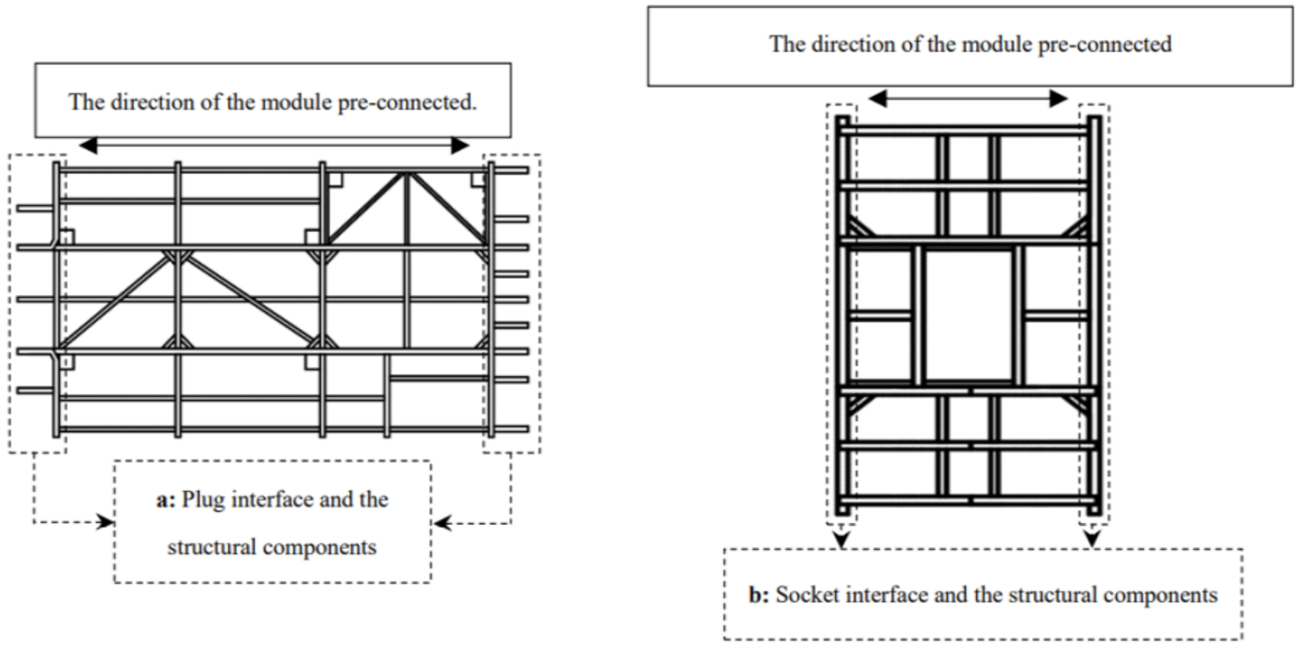
These five modules are simplified as the front frame module, the front suspension frame module, the middle frame module, the rear suspension frame module, and the rear frame module. Based on the module partition of the bus chassis, according to the layout direction of the structural components of these module interfaces, each module was characterized as either a plug type or a socket type. The corresponding modules are the plug module and the socket module, as shown in Figure 2.
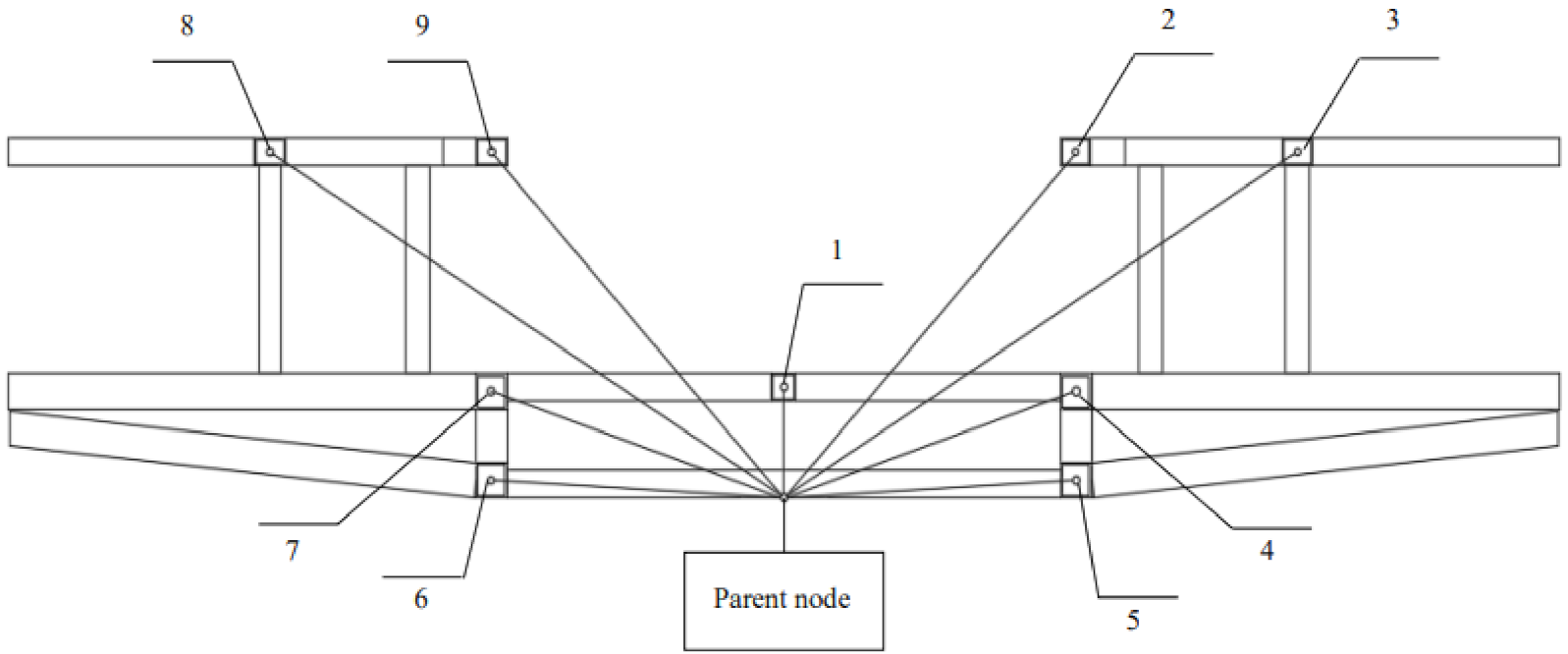
Establishment of the network of the bus chassis module interface is shown in Figure 3a,b. It consists of a parent node and child nodes. The parent node is the central fixed point of the module interface, while the child node represents the pre-connected structural components of the interface. The position of the pre-connected structural component is determined according to the relative direction and distance between the parent node and the child nodes. To complete the interface node network, the feature point method is applied to describe the connected section of pre-connected structural components. The creation and identification of the feature points of a regular structural component of the module are shown in Figure 3c.
In Figure 2 and Figure 3, each parent node represents the connectable position of an interface. In Figure 3, each child node represents a component of the plug interface, and then feature points 1, 2, 3, and 4 represent the sectional features of the component. Finally, the sectional features of all components together constitute the sectional features of a plug interface.

2.2. Construction of a Digital Expression Model of the Module Interface

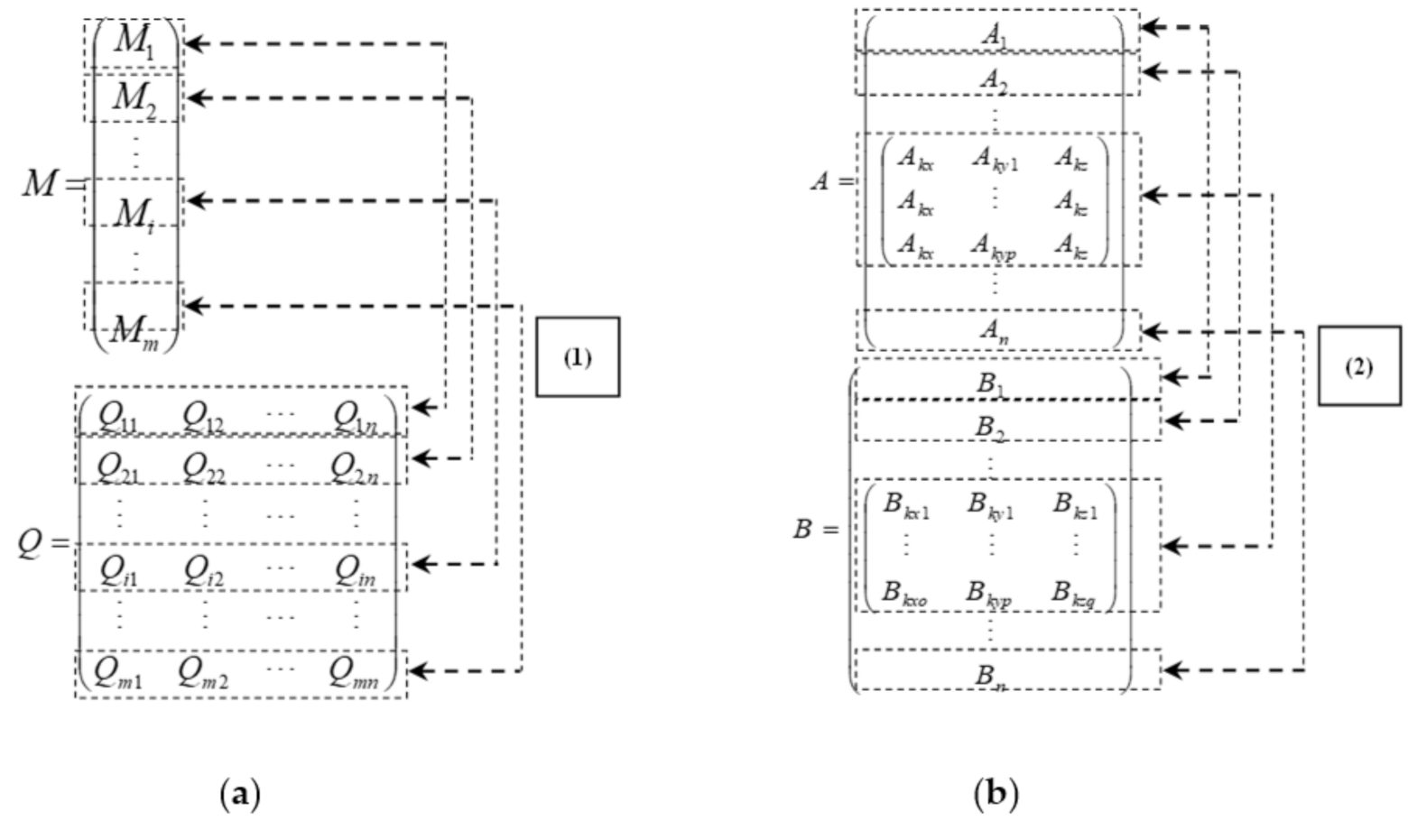
For the plug interface, the digital expression model of the interface is shown in Figure 4a, which includes the interface location matrix M and characterization matrix Q of the connection section. The location matrix M of the pre-connected structural component of the module interface is generated by the coordinate distance of each child node. The element in the matrix M represents the relative coordinates of a child node (i.e., the position of a pre-connected structural component). Each element in matrix Q is the relative coordinate of a feature point, which represents the relative direction and distance between the feature point on the connection section and the corresponding child node of the structural component.
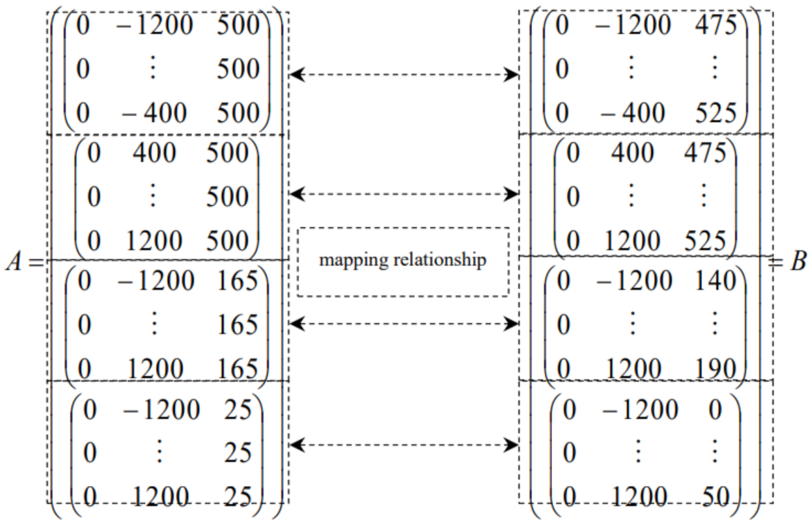
For the socket interface, the digital expression model of the interface is shown in Figure 4b, which includes the interface location matrix A and the acceptable range matrix B. Each element in the location matrix A is a block matrix, representing the position and acceptable range of a particular structural component. In the matrix B, each element is a block matrix, which represents the acceptable range of a particular structural component.

3. Criteria for Assessing the Interface Connectivity and the Reconfiguration of the Module

Based on the interface digital expression model, the following criteria are proposed for preliminarily assessing the connectivity of interfaces. Meanwhile, module reconfiguration is provided, considering the criteria.

3.1. Assessment of the Interface Connectivity

The interface connectivity needs to meet criteria defined as a parent and child relationships in the matrices. One relationship is the parent and child relationship between the plug interface location matrix M and the socket interface location matrix A. All of the nodes of the pre-connected structural components of the plug interface should be located within the acceptance scope of the related socket interface. The other relationship is the parent and child relationship between the plug interface connection section characterization matrix Q′ (calculated from the matrix Q) and the socket interface acceptable range matrix B. All the feature points on the connection section of the pre-connected structural components of the plug interface should be located within the acceptance scope of the related socket interface. The two interfaces can be interconnected when both the digital expression models of the plug interface and the socket interface satisfy the parent and child relationship.
The specific assessment criteria for the connection between module interfaces are described as follows [19]:
  • The interface types of the two pre-connected modules are different. The interface type of the pre-connected module is determined according to the layout direction of the interface of the structural components. For good complementarity and compatibility, the interface type of the two pre-connected modules needs to be different.
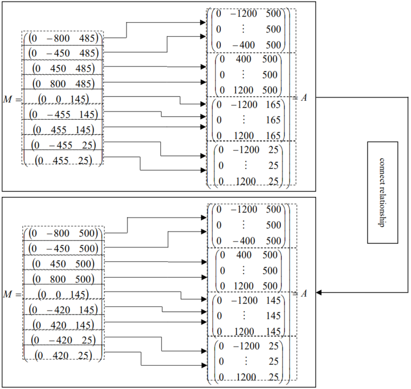
  • The interface node network fully overlaps. Taking the parent node of the plug interface as a starting point, the pre-connected module’s node network of the two interfaces need to fully overlap. The digital expression for the full overlap condition reflects the first parent and child relationship (i.e., the parent and child relationship between the location matrix M and the location matrix A). This means the location coordinates of the corresponding nodes of the pre-connected structural components of the plug interface are all within the acceptance scope of the socket interface, as shown in Figure 5a,b.
It is assumed that the pre-connected structural component (i) for the plug interface connects with the longitudinal pre-connected structural component (k) for the socket interface. The criterion for assessing the connectivity between these two structural components is reflected within the parent and child relationship between matrices based on the digital expression of the interface, as shown in Figure 5b.
3.
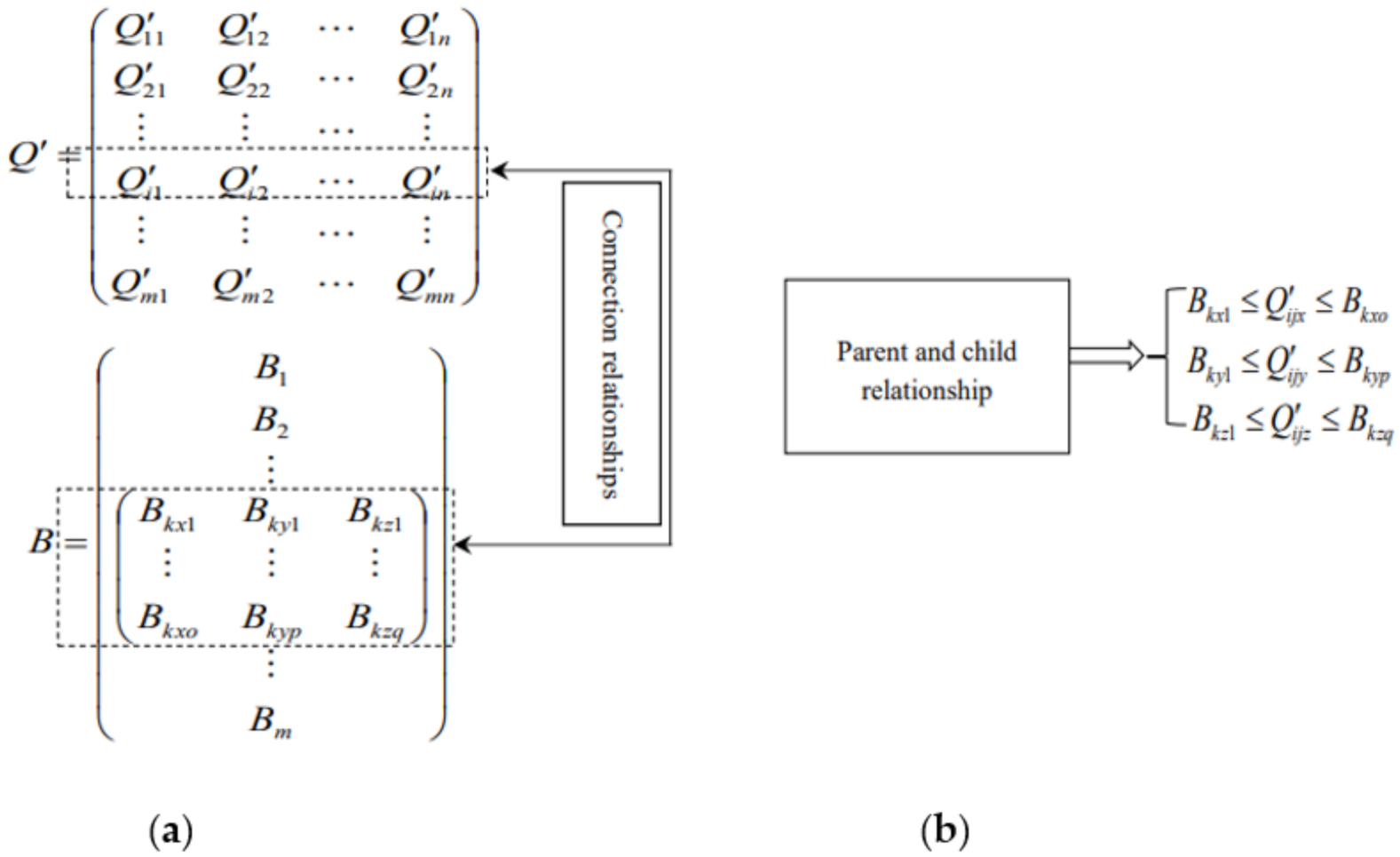
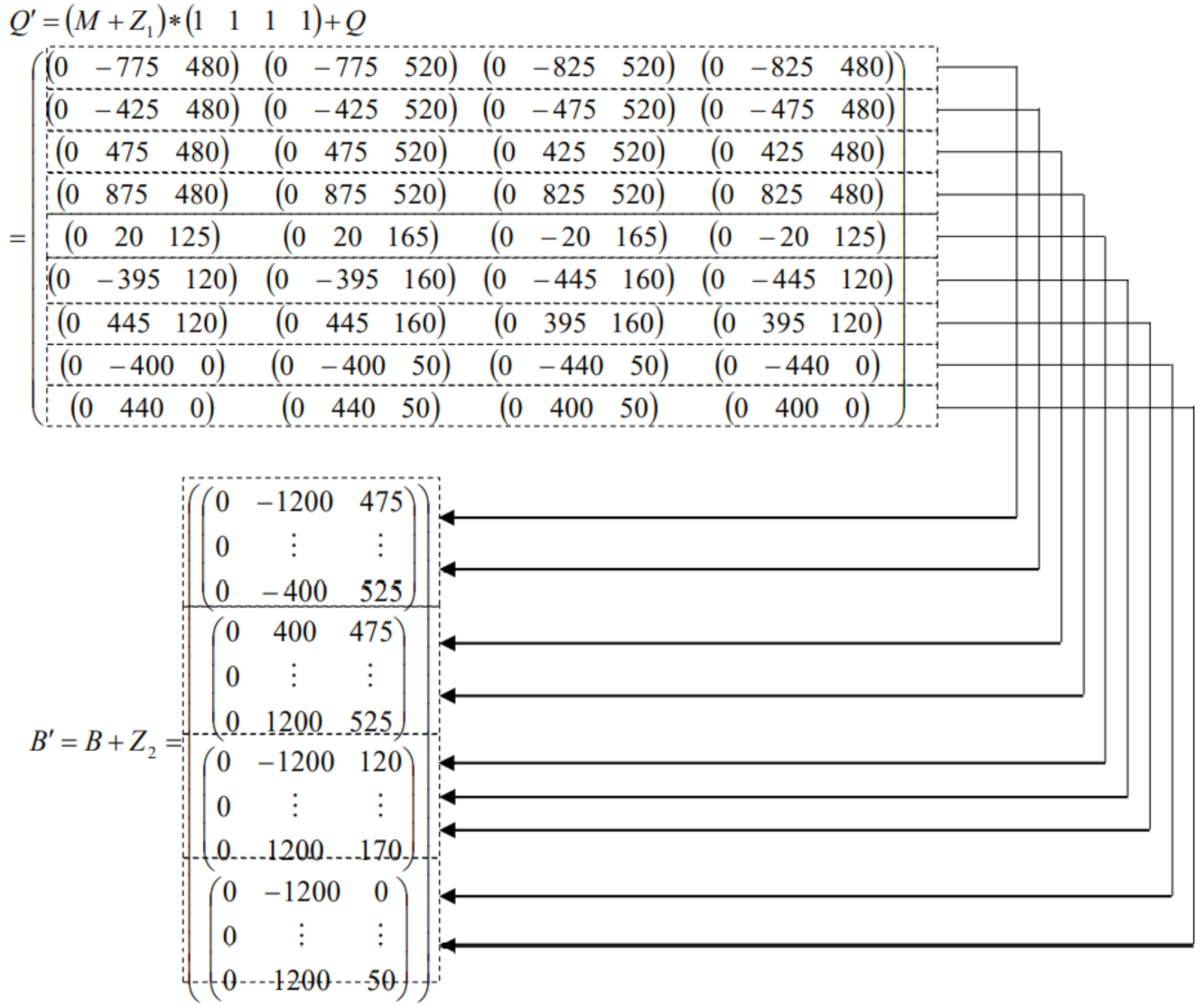
The connection sections of the pre-connected structural components are matched. Based on the full overlap of the module interfaces, another condition is to satisfy the matching requirements of the shape and size of the connection section. With the digital expression of the interface, the condition reflects the second aspect of the parent and child relationship (i.e., the parent and child relationship between the connection section characterization matrix Q′ of the plug interface and the acceptance range matrix B of the socket interface). This means that all the feature points on the connection section of the pre-connected structural components of the plug interface are within the acceptance scope of the pre-connected structural components of the socket interface, as shown in Figure 6a,b.
As an example, the pre-connected structural component (i) of the plug interface connection with the pre-connected structural component (k) of the socket interface is considered. The criterion for connectivity between the two structural components can be reflected with the parent and child relationship between matrices based on the digital expression of the interface, as shown in Figure 6b.

3.2. Module Reconfiguration Using the Criteria

Several solutions for reconfiguration using the connectivity criteria between module interfaces are explained below:
  • Reconfiguration of the interface type: Either interface type is to be reconfigured. For the plug interface type, it can be changed by adding structural components that are perpendicular to the pre-connected direction of the module. The socket interface can be changed in two ways. One way is to add pre-connected structural components that are parallel to the pre-connected direction of the module. The other way is to remove the corresponding pre-connectedstructural components. The former may change the total length of the module, while the latter does not.
  • Reconfiguration of the position of the pre-connected structural components: In order to achieve the connectivity between the two interfaces, both node networks need to fully overlap (i.e., the location of the interface pre-connected structural components can meet the matching relationship). In the real situation, some of the pre-connected structural components are adjustable and some are non-adjustable. In the process of translation of the node network, first, the non-adjustable structural components need to fully overlap. Thereafter, the position of the adjustable structural components are moved within a certain range. This proceeds until the ends of the interface node network of the two pre-connected module fully overlap.
  • Reconfiguration of the connection section of the pre-connected structural components: In order to satisfy the different types of module interfaces and the full overlap of the interface node network, it is also necessary to meet the matching relationship for each pre-connected structural component. This means that the feature points of each of the pre-connected structural components of the plug interface are within the acceptable scope of the socket interface. There are two ways to reconfigure the connection section for pre-connection of structural components. One way is to reconfigure the shape and size of the pre-connected structural components of the plug interface. This changes the relative coordinates of the corresponding feature points. The other way is to reconfigure the shape and size of the socket interface, which changes the accepted range. This is done until the ends of all the connection sections of the pre-connected structural components meet the requirements of the connection-matching relationship.

4. Reconfiguration of the Bus Chassis Module

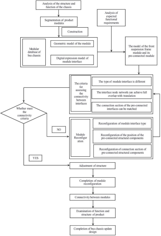
The reconfiguration process is a novel method, as shown in Figure 7. It follows the steps set out below:
  • Retrieve the module: Analyze the user needs and retrieve the appropriate modules that meet these requirements from the module database.
  • Check and reconfigure the module interface: The module interface is checked to determine if the two pre-connected modules satisfy the interface-type conditions. If the two module interface types are the same, it is necessary to reconfigure one of them.
  • Retrieving or constructing the digital expression model of the pre-connected module interfaces: The digital expression model of the plug interface includes the location matrix M and the relative characterization matrix Q of the connection section. The digital expression model of the socket interface includes the location matrix A and the acceptable range matrix B.
  • Matching and reconfiguration of the position of the pre-connected structural components of the interface: The connection matching of the position of the interface structural components is evaluated by the parent and child relationship between the location matrix M of the plug interface and the location matrix A of the socket interface. Adjustable components are reconfigured to achieve connectivity for full overlap of the interface node network.
  • Construction and operation of the process matrix: Once the module is reconfigured during the connection-matching process, the reconfiguration process matrix Z is constructed. Then, the reconfiguring of the module, the position, or the section size of a component changes, and the change is written into the matrix Z in the form of coordinates, thus forming the reconstruction process matrix. The characterization matrix Q′ of the connection section of the plug interface and the acceptable range matrix B′ of the socket interface are solved thereafter.
  • Matching and reconfiguration of the connection section of the pre-connected structural components: Based on step (5), matching of the connection section of the interface structural components is evaluated by the parent and child relationship between the characterization matrix Q′ for the connection section of the plug interface and the acceptable range matrix B′ of the socket interface. Meanwhile, the connection section of the adjustable structural components is reconfigured to meet the requirements of the matching relationship.
  • Completion of the module reconfiguration: The connection-matching relationship of the module interface is checked, and then the pre-connected module is reconfigured based on the calculation results. The module can be fine-tuned according to the actual engineering needs, until the final design of the module is completed.
As mentioned in step (5), the reconfiguration process matrix Z of the module was constructed based on the results of the above-mentioned process. The characterization matrix Q′ of the connection section of the plug interface and the acceptable range matrix B′ of the socket interface are solved by the equation below:
Q = M + Z 1 × 1 1 1 R o w   m a t r i x ,   a   t o t a l   o f   n   e l e m e n t s ,   e a c h   e l e m e n t   i s   1 + Q
In Equation (1), Q′ is the characterization matrix of the connection section of the plug interface; M is the location matrix of the plug interface without reconfiguration; Z1 is the process matrix of the reconfiguration of the plug interface; and Q is the relative characterization matrix of the connection section of the plug interface.
B′ = B + Z2
In Equation (2), B′ is the acceptable range matrix of the socket interface with reconfiguration; B is the acceptable range matrix of the socket interface without reconfiguration; and Z2 is the process matrix of the reconfiguration of the socket interface.
Using the above equations, the characterization matrix Q′ of the plug interface and the acceptable range matrix B′ of the connection section of the socket interface with the reconfiguration are obtained.

5. Case Study

In this study, the use of the proposed method is exemplified by the reconfiguration and replacement of the front suspension frame module of a bus chassis. This module satisfies the requirements of function and performance. It is retrieved from the module database, depending on the user’s needs. Subsequently, the digital expression model of the interface of the selected module and the pre-connected module is constructed. Thereafter, the connection matching the front suspension frame module and the middle frame module is assessed, after which two modules are reconfigured according to the proposed method. The connections of the chassis module interfaces are established and the purpose of product update design is finally achieved.

5.1. The Modular Design Process for the Bus Chassis

The updated design process for the bus chassis is illustrated in Figure 8.

5.2. Construction of the Digital Expression Model of the Pre-Connected Module Interface

Based on the layout direction of the constituent structural components of the interface, it is inferred that the front interface of the middle frame module is a plug interface. The interface node network of this module is constructed, as shown in Figure 9, and the relevant information is extracted, as shown in Table 1.
Table 1 shows the information for the front interface of the middle frame module, in which the adjustable child nodes represent the adjustable position of the pre-connected structural components. Bearing in mind that the interface module is layered along the z direction, the child nodes that have the same or the similar vertical coordinates are assigned to the same layer. Using the information in Table 1, the digital expression model of the front interface of the middle module is constructed, as shown in Figure 10. The model includes the interface location matrix M and the relative characterization matrix Q of the connection section. There is a mapping relationship between the two matrices. It reflects the number of rows of the two matrices that are equal. For example, the row (i) in the matrix M and the matrix Q, respectively, reflects the location and the geometric information of the pre-connected structural components numbered (i).
Based on the layout direction of the structural components of the interface, it is inferred that the rear interface of the front suspension frame module is a socket interface. The interface node network of the module is constructed, as shown in Figure 11, and the relevant information is extracted, as shown in Table 2.
Table 2 contains the information for the rear interface of the front suspension frame module, in which the adjustable child nodes represent the adjustable position of the pre-connected structural components. The digital expression model includes the interface location matrix A and the acceptable range matrix B. The accepted ranges in matrices A and B are based on the addition of their position coordinates and the accepted relative ranges, as shown in Equations (3)–(5), where the subscript L corresponds to the direction of location of structural components and the subscript R corresponds to the direction of relative acceptable structural components. Using the information in Table 2 and the Equations (3)–(5), the digital expression model of the interface of the front suspension frame module is thereby constructed, as shown in Figure 12. A mapping relationship between the two matrices exists, which reflects the number of rows of the two matrices that are equal. For example, the row (k) in the matrix A represents the coordinate location of the pre-connected structural component numbered (k). At the same time, the row (k) in the matrix B reflects the acceptable range of the pre-connected structural component numbered (k).
A 1 = x y z = x L y L z L + 0 y R 0 = x L y L + y R z L = x L y L + y R m i n z L x L y L + y R m a x z L
B 1 = A + 0 0 z R = x L y L + y R m i n z L + z R m i n x L y L + y R m a x z L + z R m a x
A = A 1 A n                   B = B 1 B n

5.3. Confirmation of the Matching Relationship of the Module Connection and Reconfiguration Based on the Connectivity Criteria

Once the digital expression model for the module interfaces is complete, the connection matching assessment and the reconfiguration of the retrieved module and its pre-connected module are carried out. According to the proposed method, the specific operational steps are as follows:
  • Retrieve the front suspension frame module: The user’s needs are analyzed, and the front suspension frame module that meets the functions and performance requirements is retrieved from the module database.
  • Check and reconfigure the design of the type of module interface: The type of the interface of the front suspension frame module and the interface of the middle frame module is checked. Analysis shows that the rear interface of the front suspension frame module is a socket interface, while the front interface of the middle module is a plug interface. This satisfies the first criterion of the connection between module interfaces (i.e., the type of the two pre-connected interfaces must be different). Therefore, there is no need to reconfigure this module interface.
  • Construction of the digital expression model of module interface: The digital expression model of the rear interface of the front suspension frame module and the front interface of the middle front module is constructed. For the middle module, the model includes the interface location matrix M and the relative representation matrix Q for the connection section. For the front suspension module, the model includes the interface location matrix A and the acceptable range matrix B.
  • Matching and reconfiguring the position of the pre-connected structural components of the module interface: The second criterion, indicating that the two modules can be connected, is used (i.e., whether the node network of the module interface can overlap fully with the translation). The interface location matrix M of the middle frame module and the interface location matrix A of the front suspension framework module are obtained from the digital expression model. Thereafter, the connection matching relationship between the pre-connected structural components is assessed based on the relationship between the matrices M and A. Finally, some adjustable structural components are reconfigured to meet the requirements of the connection-matching modules. The design results are shown in Figure 13.
  • Construction and operation of the process matrix: The front suspension frame module and the middle frame module have been reconfigured in step (4). Subsequently, the reconfiguration process matrices Z1 and Z2 of the two modules are constructed according to the results of the design, respectively, as shown in Equation (6). Z1 is the process matrix of the middle frame module and Z2 is the process matrix of the front suspension frame module.
    Z 1 = Δ M = 0 0 15 0 0 15 0 0 15 0 0 15 0 0 0 0 35 0 0 35 0 0 35 0 0 35 0     Z 2 = Δ Q = 0 0 0 0 0 0 0 0 0 0 0 0 0 0 0 0 0 0 0 0 20 0 0 20 0 0 20 0 0 20 0 0 20 0 0 20
  • Matching and reconfiguring the design of the connection section of the pre-connected structural components: Using the reconfiguration results in step (5), the connection section characterization matrix Q′ of the middle frame module interface and the acceptance range matrix B′ of the front suspension frame interface are calculated. The third criterion for module interface connectivity is then evaluated (i.e., the matching relation of the connection section of the pre-connected structural components), as shown in Figure 14. The criterion is digitally expressed as the parent and child relationship between the matrix Q′ and the matrix B′. Results show that the connection section of the pre-connected component meets the requirement for the connection-matching relationship. Therefore, it is not necessary to reconfigure the connection section further.
  • Completion of the reconfiguration of the module: The connection-matching relationship of the module interface is checked. Thereafter, reconfiguration of the modules is completed and the connectivity between the modules is established, according to the above calculation results.
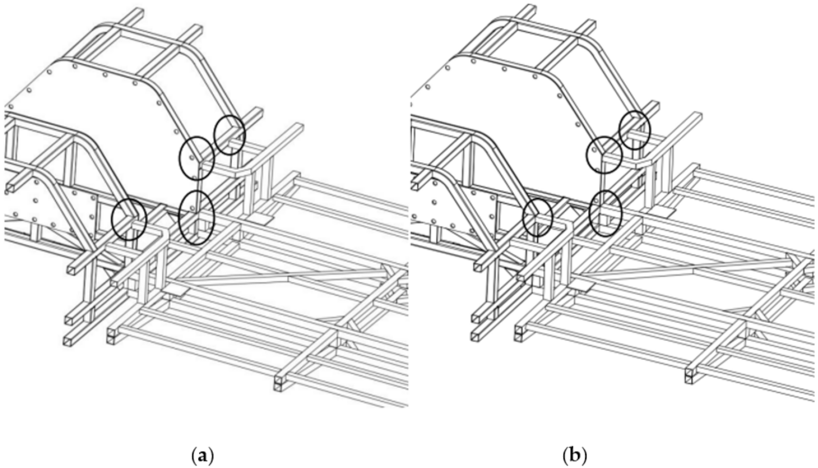
In summary, according to the calculation results, the front suspension frame module and the middle frame module were reconfigured and the connectivity between the two modules was established. The assembly of the two modules is shown in Figure 15a,b.

5.4. Updated and Improved Design of the Bus Chassis

The connection matching of the front suspension frame module and the front frame module was assessed using the developed method. The two modules were reconfigured by combining the actual engineering set-up. Thereafter, the assembly between the modules was completed when the end of the replacement of the front suspension frame module was completed. The integrity of the function and structure of the bus chassis was checked after the design completion. Respectively, the bus chassis with and without the replacement of the front suspension frame module is shown in Figure 16a,b.
In summary, the front suspension frame module that meets the functional and performance requirements was retrieved, based on users’ needs. The front suspension frame module and its pre-connected modules were then reconfigured, considering the connectivity between the modules. Finally, the connectivity of modules with the reconfiguration was established. This research updates the knowledge and the state of the art for the modular design of the bus chassis, using replacement of the front suspension frame module as an example.

6. Conclusions

In this paper, a novel reconfiguration method was applied based on the connectivity between bus chassis modules, and was subsequently used to guide the reconfiguration process. The following conclusions were reached:
  • The digital expression of the chassis module interface provides criteria for assessing the connectivity between modules. Connectivity between modules can be identified quickly and accurately through the parent and child relationship using the matrices of the digital expression for the interface. This greatly improves the efficiency of the modular design. At the same time, the connection criterion perfects the digital expression method of the module interface and improves the implementation of the digital expression method.
  • A reconfiguration method for modules, based on the digital expression of the module interface, was proposed and implemented for a real-world case bus chassis. This method is oriented to the connectivity between modules. It relies on the guidance of their reconfiguration of the module through the digital operation, step by step. This improves the versatility and interchangeability of the module. The method could be applied in the future to the reconfiguration of a product module with a similar truss structure.
  • In the actual process of product design, the module reconfiguration method based on the interface digital expression method can quickly determine whether the original module can be borrowed and applied through the numerical relationship of the interface matrix, and show module reconfiguration through the numerical relationship. The borrowing or reconfiguration of original modules greatly reduces the development cost of new modules and products and plays an important role in helping enterprises to implement platform and diversified products.
  • In addition, in this study, the specific connection methods for the interface in the manufacturing process, such as the welding process for the bus chassis frame and the welding strength, were not discussed, and further research is needed in the future.
In this study, the reconfiguration and replacement of the front suspension frame module of a bus chassis was used as an example to illustrate the validity and effectiveness of the proposed method.
The present study mainly describes the methodology and discusses the implementation of this method in a bus chassis based on homogeneous materials with various interfaces. However, the following factors need to be considered in the future:
  • The strength and stiffness of bus chassis modules should be investigated to identify the effect of reconfiguration on mechanical behavior.
  • The connections between hybrid material linkages should be further investigated, as the welding parameters and the connection techniques may be different.
  • The implementation of this method in manufacturing requires a comprehensive study, including consideration of the assembly sequence and associated equipment.

Author Contributions

Conceptualization, Q.P. and M.R.; methodology, Q.P., X.M. and S.L.; validation, X.M. and S.L.; writing—original draft preparation, X.M. and S.L.; writing—review and editing, Q.P., M.R. and F.H.; supervision, M.R. All authors have read and agreed to the published version of the manuscript.

Funding

This research was funded by the National Natural Science Foundation of China under Grant 51505403; the 2011 Program of Bus and Specialty Vehicle Research & Design Collaborative Innovation Centre in Fujian Province under Grant 2016AYF004; and the National High-End Expert Programme (HEEP) under Grant GDT20183600413.

Institutional Review Board Statement

Not applicable.

Informed Consent Statement

Not applicable.

Data Availability Statement

Not applicable.

Conflicts of Interest

The authors declare no conflict of interest.

References

  1. Boulanger, A.G.; Chu, A.C.; Maxx, S.; Waltz, D.L. Vehicle Electrification: Status and Issues. Proc. IEEE 2011, 99, 1116–1138. [Google Scholar] [CrossRef] [Green Version]
  2. Mahmoud, M.; Garnett, R.; Ferguson, M.; Kanaroglou, P. Electric buses: A review of alternative powertrains. Renew. Sustain. Energy Rev. 2016, 62, 673–684. [Google Scholar] [CrossRef]
  3. Dreier, D.; Silveira, S.; Khatiwada, D.; Fonseca, K.V.O.; Nieweglowski, R.; Schepanski, R. Well-to-Wheel analysis of fossil energy use and greenhouse gas emissions for conventional, hybrid-electric and plug-in hybrid-electric city buses in the BRT system in Curitiba, Brazil. Transp. Res. Part D Transp. Environ. 2018, 58, 122–138. [Google Scholar] [CrossRef]
  4. Du, J.; Ouyang, M.; Chen, J. Prospects for Chinese electric vehicle technologies in 2016–2020: Ambition and rationality. Energy 2017, 120, 584–596. [Google Scholar] [CrossRef]
  5. Napper, R. Modular route bus design—A method of meeting transport operation and vehicle manufacturing requirements. Transp. Res. Part C Emerg. Technol. 2014, 38, 56–72. [Google Scholar] [CrossRef]
  6. Millo, F.; Rolando, L.; Fuso, R.; Zhao, J. Development of a New Hybrid Bus for Urban Public Transportation. Appl. Energy 2015, 157, 583–594. [Google Scholar] [CrossRef]
  7. Leng, J.; Liu, Q.; Ye, S.; Jing, J.; Wang, Y.; Zhang, C.; Zhang, D.; Chen, X. Digital twin-driven rapid reconfiguration of the automated manufacturing system via an open architecture model. Robot. Comput. Manuf. 2020, 63, 101895. [Google Scholar] [CrossRef]
  8. Baldwin, C.Y.; Clark, K.B. Managing in an age of modularity. Harv. Bus. Rev. 1997, 75, 84–93. [Google Scholar]
  9. Piran, F.; Lacerda, D.; Camargo, L.F.R.; Viero, C.F.; Dresch, A.; Cauchick-Miguel, P.A. Product modularization and effects on efficiency: An analysis of a bus manufacturer using data envelopment analysis (DEA). Int. J. Prod. Econ. 2016, 182, 1–13. [Google Scholar] [CrossRef]
  10. Ulrich, K. Fundamentals of Product Modularity. In Management of Design: Engineering and Management Perspectives; Dasu, S., Eastman, C., Eds.; Springer: Dordrecht, The Netherlands, 1994; pp. 219–231. [Google Scholar]
  11. Alizon, F.; Khadke, K.; Thevenot, H.J.; Gershenson, J.K.; Marion, T.J.; Shooter, S.B.; Simpson, T.W. Frameworks for Product Family Design and Development. Concurr. Eng. 2007, 15, 187–199. [Google Scholar] [CrossRef]
  12. Bruun, H.P.L.; Mortensen, N.H.; Harlou, U. Interface diagram: Design tool for supporting the development of modularity in complex product systems. Concurr. Eng. 2013, 22, 62–76. [Google Scholar] [CrossRef]
  13. Salvador, F.; Forza, C.; Rungtusanatham, M. Modularity, product variety, production volume, and component sourcing: Theorizing beyond generic prescriptions. J. Oper. Manag. 2002, 20, 549–575. [Google Scholar] [CrossRef]
  14. Barbosa, L.M.; Lacerda, D.; Piran, F.; Dresch, A. Exploratory analysis of the variables prevailing on the effects of product modularization on production volume and efficiency. Int. J. Prod. Econ. 2017, 193, 677–690. [Google Scholar] [CrossRef]
  15. Pires, S.R. Managerial implications of the modular consortium model in a Brazilian automotive plant. Int. J. Oper. Prod. Manag. 1998, 18, 221–232. [Google Scholar] [CrossRef]
  16. ISE Corporation. 2007. Available online: http://www.isecorp.com (accessed on 20 December 2021).
  17. Habib, T.; Kristiansen, J.N.; Rana, M.B.; Ritala, P. Revisiting the role of modular innovation in technological radicalness and architectural change of products: The case of Tesla X and Roomba. Technovation 2020, 98, 102163. [Google Scholar] [CrossRef]
  18. Schuh, G.; Arnoscht, J.; Rudolf, S.; Korthals, K. Modular Chassis Product Platform Considering Variable Quantities for an Economical Electric Vehicle Production; Springer: Berlin/Heidelberg, Germany, 2013; pp. 73–82. [Google Scholar]
  19. Peng, Q.; Liu, S.; Robinson, M.; Han, F.-G.; Matsika, E. A digital expression method for the module interface in a practical bus chassis modular design and case history. Concurr. Eng. 2018, 26, 355–366. [Google Scholar] [CrossRef] [Green Version]
  20. Tao, F.; Cheng, J.; Qi, Q.; Zhang, M.; Zhang, H.; Sui, F. Digital twin-driven product design, manufacturing and service with big data. Int. J. Adv. Manuf. Technol. 2017, 94, 3563–3576. [Google Scholar] [CrossRef]
  21. Rassolkin, A.; Vaimann, T.; Kallaste, A.; Kuts, V. Digital twin for propulsion drive of autonomous electric vehicle. In Proceedings of the 2019 IEEE 60th International Scientific Conference on Power and Electrical Engineering of Riga Technical University (RTUCON), Riga, Latvia, 7–9 October 2019. [Google Scholar] [CrossRef]
  22. Bhatti, G.; Mohan, H.; Singh, R.R. Towards the future of smart electric vehicles: Digital twin technology. Renew. Sustain. Energy Rev. 2021, 141, 110801. [Google Scholar] [CrossRef]
  23. Koren, Y.; Hu, S.; Gu, P.; Shpitalni, M. Open-architecture products. CIRP Ann. 2013, 62, 719–729. [Google Scholar] [CrossRef]
  24. Baldwin, C.Y.; Clark, K.B. Design Rules Volume I: The Power of Modularity; MIT Press: Cambridge, MA, USA, 2000; Volume 1. [Google Scholar]
  25. Ulrich, K. The role of product architecture in the manufacturing firm. Res. Policy 1995, 24, 419–440. [Google Scholar] [CrossRef] [Green Version]
  26. Chen, K.-M.; Liu, R.-J. Interface strategies in modular product innovation. Technovation 2005, 25, 771–782. [Google Scholar] [CrossRef]
  27. Cabigiosu, A.; Zirpoli, F.; Camuffo, A. Modularity, interfaces definition and the integration of external sources of innovation in the automotive industry. Res. Policy 2013, 42, 662–675. [Google Scholar] [CrossRef] [Green Version]
  28. Bonvoisin, J.; Halstenberg, F.; Buchert, T.; Stark, R. A systematic literature review on modular product design. J. Eng. Des. 2016, 27, 488–514. [Google Scholar] [CrossRef]
  29. Pereira, M.; Weingaertner, W.; Forcellini, F. Design Methodology for Reconfigurable Precision Systems Applied to a Sclerometer Development; Cirp-International Seminar on Manufacturing Systems: Florianopolis, Brazil, 2005. [Google Scholar]
  30. Hölttä, K.M.; Otto, K.N. Incorporating design effort complexity measures in product architectural design and assessment. Des. Stud. 2005, 26, 463–485. [Google Scholar] [CrossRef]
  31. Usha, K.; Upadhyaya, S. An interface complexity measure for component-based software systems. Int. J. Comput. Appl. 2011, 36, 46–52. [Google Scholar]
  32. Oh, K.; Kim, H.W.; Kim, D.; Lee, J.; Lee, J.; Hong, Y.S. Product Interface Design for Complexity Management in Assembly Systems. IEEE Access 2020, 8, 225491–225506. [Google Scholar] [CrossRef]
  33. Ulrich, K.T.; Eppinger, S.D. Product Design and Development; Tata McGraw-Hill Education: New York, NY, USA, 2003. [Google Scholar]
  34. Sinha, K.; de Weck, O.L. Structural Complexity Quantification for Engineered Complex Systems and Implications on System Architecture and Design. In Proceedings of the ASME 2013 International Design Engineering Technical Conferences and Computers and Information in Engineering Conference, Portland, OR, USA, 4–7 August 2013. [Google Scholar] [CrossRef] [Green Version]
  35. Sheard, S.A.; Mostashari, A. 7.3.1 A Complexity Typology for Systems Engineering. In Proceedings of the INCOSE International Symposium, Chicago, IL, USA, 12–15 July 2010; Wiley Online Library: Hoboken, NJ, USA, 2010; pp. 933–945. [Google Scholar]
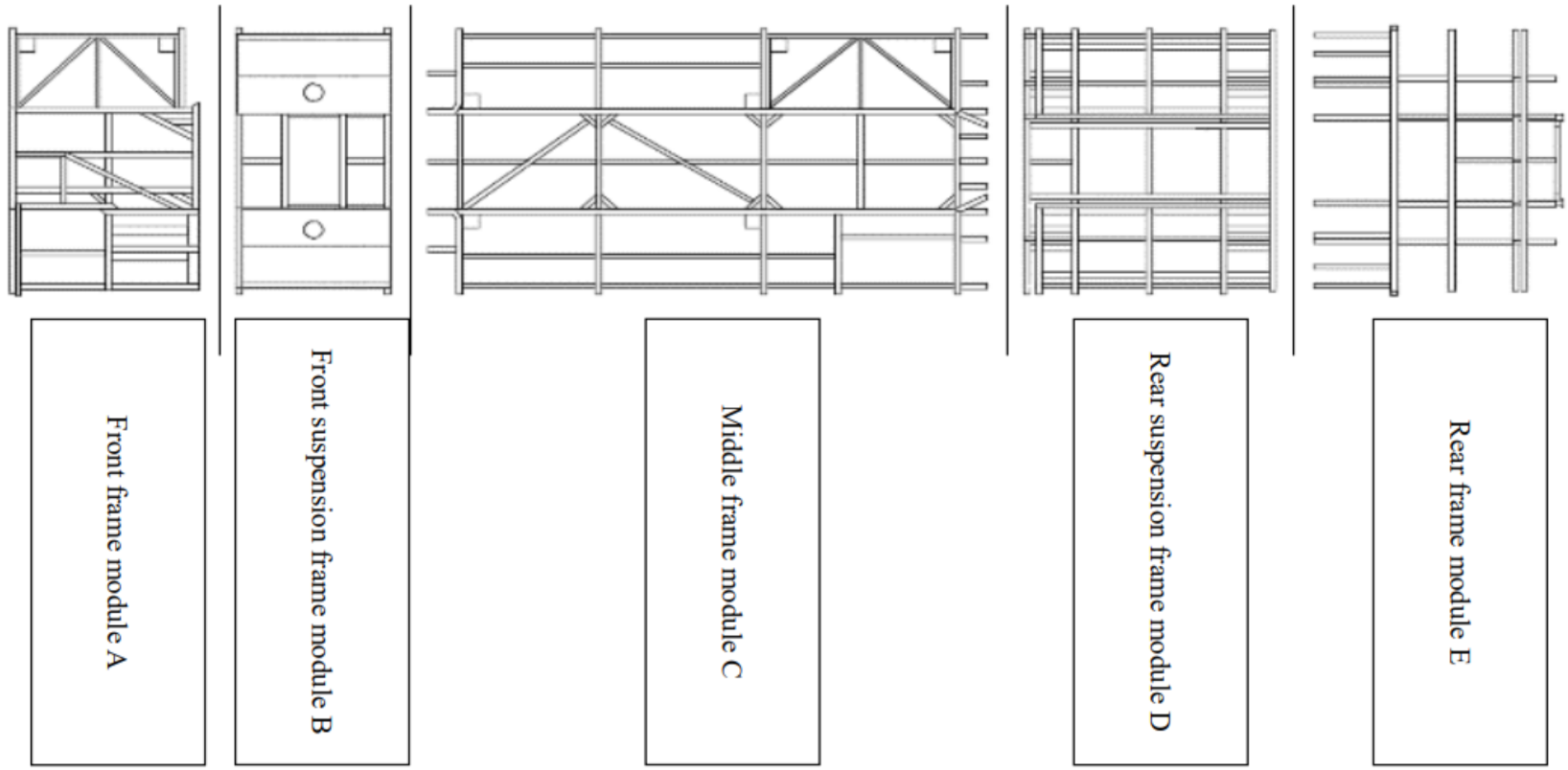
Figure 1. Bus chassis modules defined according to their functions and positions: (A) front frame module; (B) front suspension frame module; (C) middle frame module; (D) rear suspension frame module; and (*E) rear frame module. (Top view of a bus chassis).
Applsci 12 03274 g001
Figure 2. (a) Plug interface and the corresponding module, showing that the layout direction of the structural components is consistent with the pre-connected direction of the module, showing the top view of the middle frame module and the plug interface; (b) Socket interface and the corresponding module, showing that the layout directions of the structural components are perpendicular to the pre-connected direction of the module, showing the top view of the rear suspension frame module and the socket interface. The pre-connected direction in the figure refers to the direction that the module is ready to be assembled with other modules. For example, the middle frame module of bus chassis is ready to be connected with the front suspension or rear suspension frame module, so the front and rear directions of the module are the pre-connected directions.
Applsci 12 03274 g002
Figure 3. (a) Node network of plug interface; the parent node represents the center point and each child node represents one of the pre-connected structural components. Shown is the front view of a middle frame module and the plug interface; (b) Node network of socket interface; the parent node represents the center point and each child node represents one of the pre-connected structural components. Shown is the front view of a rear suspension frame module and the socket interface; (c) Creation and identification of the feature points of a regular structural component section. shown is a cross-section diagram of a truss of the plug interface.
Applsci 12 03274 g003
Figure 4. (a) Digital expression model of the plug interface; matrix M represents the location of components and matrix Q represents the connection section of components; (b) Digital expression model of socket interface; matrix A represents the interface location and matrix B represents the acceptable range.
Applsci 12 03274 g004
Figure 5. (a) The connection relationship between structural component numbered (i) and structural component numbered (k); (b) The parent and child relationship between matrix Mi and matrix Ak.
Applsci 12 03274 g005
Figure 6. (a) The connection relationship between structural component (i) and structural component (k); (b) The parent and child relationship between matrix Qij and matrix.
Applsci 12 03274 g006
Figure 7. Process of module reconfiguration based on the interface digital expression model.
Applsci 12 03274 g007
Figure 8. The updated design process for the bus chassis.
Applsci 12 03274 g008
Figure 9. Schematic diagram of the front interface node network of the middle frame module; the node numbers are referred in Table 1.
Applsci 12 03274 g009
Figure 10. Digital expression model of the front interface of the middle frame module.
Applsci 12 03274 g010
Figure 11. Schematic diagram of the rear interface node network of the front suspension frame module; the node numbers are referred to in Table 2.
Applsci 12 03274 g011
Figure 12. Digital expression model of the rear interface node network of the middle frame module.
Applsci 12 03274 g012
Figure 13. Confirmation of connection relationships between modules and module reconfigurations.
Applsci 12 03274 g013
Figure 14. Confirmation of connection section relationship between modules and module reconfiguration.
Applsci 12 03274 g014
Figure 15. (a) Connections between the front suspension frame module and the middle frame module (without reconfiguration); (b) Connections between the front suspension frame module and the middle frame module (with reconfiguration).
Applsci 12 03274 g015
Figure 16. (a) Bus chassis without a replaced front suspension frame module; (b) Bus chassis with a replaced front suspension frame module.
Applsci 12 03274 g016
Table 1. Information for the front interface of the middle frame module (mm).
Node NumberAdjustableLocation of Child Node Description of Pre-Connected ComponentsRelative Coordinates of Feature Points
xyz
1N00145Square
40 × 40
Number
Coordinate(0, 20, −20)(0, 20, 20)(0, −20, 20)(0, −20, −20)
2Y0−450485Rectangle
50 × 40
Number
Coordinate(0, 25, −20)(0, 25, 20)(0, −25, 20)(0, −25, −20)
3Y0−800485Rectangle
50 × 40
Number
Coordinate(0, 25, −20)(0, 25, 20)(0, −25, 20)(0, −25, −20)
4N0−455145Square
50 × 50
Number
Coordinate(0, 25, −25)(0, 25, 25)(0, −25, 25)(0, −25, −25)
5N0−45525Square
50 × 50
Number
Coordinate(0, 25, −25)(0, 25, 25)(0, −25, 25)(0, −25, −25)
6N045525Square
50 × 50
Number
Coordinate(0, 25, −25)(0, 25, 25)(0, −25, 25)(0, −25, −25)
7N0455145Square
50 × 50
Number
Coordinate(0, 25, −25)(0, 25, 25)(0, −25, 25)(0, −25, −25)
8Y0800485Rectangle
50 × 40
Number
Coordinate(0, 25, −20)(0, 25, 20)(0, −25, 20)(0, −25, −20)
9Y0450485Rectangle
50 × 40
Number
Coordinate(0, 25, −20)(0, 25, 20)(0, −25, 20)(0, −25, −20)
Table 2. Information for the rear interface of the front suspension frame module (mm).
Node NumberingLayout Direction of Structural ComponentWhether It Is AdjustableLocation of Structural ComponentsRelative Acceptable Range of Structural Components
y Directionz Directionx Directiony Directionz Direction
1Parallel to the y directionYN0−800500Directionyz
Range value−400400−2525
2Parallel to the y directionYN0800500Directionyz
Range value−400400−2525
3Parallel to the y directionYY00165Directionyz
Range value−12001200−2525
4Parallel to the y directionYY0025Directionyz
Range value−12001200−2525
Publisher’s Note: MDPI stays neutral with regard to jurisdictional claims in published maps and institutional affiliations.