Abstract
The main components of a liquid breeder blanket in a fusion power reactor are lead lithium alloy (PbLi) and the steel structure in which the liquid is enclosed (EUROFER). Several compatibility tests have shown that structural materials always suffer from corrosion attacks. The governing mechanism can be attributed to the dissolution of the steel by the liquid breeder and is strongly related to the PbLi chemistry, velocity profile, and temperature. A new facility, CiCLo-C (CIEMAT Corrosion Loop, Internally Coated), is dedicated to the study of corrosion in materials under the severe breeding blanket condition. An effort was made to design an experimental facility with a specific test section able to work at quite ambitious operation parameters: up to 550 °C and a 1 m/s flow of PbLi. Furthermore, an innovative tantalum coating was introduced in the whole loop to avoid impurities coming from the pipeline, which can disturb the measurements, and to better preserve the installation.
1. Introduction
The chemical compatibility of breeding and structural materials is essential for safe and reliable system operation in nuclear fusion reactors. The eutectic alloy Pb-17Li, enriched at 90% in 6Li, and reduced activation ferritic–martensitic (RAFM) steels, such as EUROFER, are the breeder and the structural material candidates, respectively, used in fusion reactors’ breeding blanket (BB) concepts under investigation in Europe for future fusion machines [1,2]. The fuel of the fusion reaction is composed of two hydrogen isotopes, deuterium and tritium, which fuse to yield a helium nucleus and one unique neutron of approximately 14 MeV. Deuterium is abundant in nature, but tritium is a fast-decaying radioelement that has to be produced inside a reactor [3] obtaining so-called self-sufficiency. Thus, in all the BB concepts, tritium is produced inside the blanket following the reactions (n is the neutron coming from the fusion reaction):
taking into account that lithium, which is composed of two stable isotopes (isotopic composition 6Li 7.4% and 7Li 92.6%), presents a low nuclear binding energy per nucleon [4]. Another key aspect is that not all neutrons produced by fusion reactions interact with the blanket (approximately 20% [5]); therefore, they will not produce tritium. Considering that the fusion reaction only releases one neutron, the self-sufficiency of the reactor cannot be guaranteed. For this reason, neutron multipliers, such as Pb, are required. Thus, a PbLi alloy enriched to 90% in 6Li, circulating in loops through the BB internals, provides a tritium breeder, a neutron multiplier, and a tritium carrier, hence playing an important role in reactor operation. The advantages of using PbLi are due to the nuclear properties of the eutectic (since the breeder and neutron multiplier are combined in the same material) and the chemical properties (since the eutectic does not exhibit an explosive reaction when in contact with air and water) [6,7]. The main drawback is its compatibility with materials due to its high corrosion grade. Corrosion can result in significant material thinning/wastage and the deposition of corrosion products, which may cause severe flow restrictions and excessive accumulation of radioactive material in unshielded regions.
6Li + n(slow) → 4He + 3T + 4.8 MeV
7Li + n(fast) → 4He + 3T + n − 2.5 MeV
Within the European Fusion Technology Program, much effort has been placed on developing appropriate steels because of safety requirements, as it is mandatory to minimize problems associated with induced radioactivity in the structural materials. Several ferritic–martensitic steels, such as MANET, OPTIFER, F82H, CLAM, and so on, have been developed worldwide. The progress of the research activities in Europe has resulted in the formulation of the RAFM steel named EUROFER (9% Cr, 1% WVTa) [8].
The implementation of structural materials in blanket applications required a detailed study on chemical compatibility with a special focus on corrosion behavior. Considering that the structural material must maintain its integrity under large temperature gradients, severe thermal cycling, and intense irradiation, the compositional and microstructural changes due to selective dissolution and intergranular corrosion can lead to material failures [9]. The former consequence results in a loss of mechanical integrity, the creation of several impurities flowing in the system, and consequent load losses that increase the requirements for pumping power, decreasing the energy conversion efficiency and complicating system maintenance [10].
Several experiments have been performed over the past years in different international facilities, focusing on various aspects of PbLi flow and its interaction with structural and functional materials for fusion applications [11,12,13,14,15,16,17,18,19,20]. Although a good understanding of lithium lead behavior has been achieved, many compatibility problems with EUROFER as a structural material are still unresolved, especially in several blanket relevant conditions. These include cases of a high lithium lead flow rate together with a high temperature [21], chemical compatibility with coating materials [22], or the effect of radiation on the corrosion layer [23]. The changing experimental conditions have demonstrated that the corrosion attack can drastically change when the temperature changes at a given flow velocity [24], both of which are very important parameters for EUROFER corrosion dynamics.
The state of the art of liquid metal technologies and their future development in fusion research demands the construction of new infrastructure in Europe that could be devoted to the research on several topics, such as the training of scientists and engineers for the industrial development of liquid metal technology in the fusion field, together with the transfer of knowledge and technology among research centers and facilities, universities, and industry to establish competent human teams for the deployment of future fusion devices. For this reason, the prime objective of the CIEMAT Liquid Metal Laboratory (LML) is to achieve new experimental conditions able to cover the gap present in the literature and to study the main concerns related to PbLi technologies in future fusion reactors [25,26]. In this frame, a new facility, the CIEMAT Corrosion Loop, Internally Coated (CiCLo-C), has been designed with the aim of evaluating the corrosion behavior of EUROFER steel and other fusion relevant materials when they are exposed to the liquid metal alloy flow rate. According to the literature, a high mass loss has been observed in steel tested materials (~20–900 µm/year) [27]. Thus, it is reasonable to think that this corrosion can also affect the steel pipeline of the system rather than only the specimens. In this scenario, the chemistry of the liquid metal can be severely modified, thus also affecting the corrosion process [28]. In order to prevent this situation, the pipes in CiCLo-C will be internally coated with tantalum. Tantalum has been demonstrated to have corrosion resistance [29]. The main purpose will be to ensure that observed corrosion products in the liquid metal are derived exclusively from the specimens, thus not modifying the experimental conditions (the chemistry of the liquid metal) and assuring the isolation of the corrosion effect on the specimens. In addition, this protection will extend the lifetime of the facility.
An added value to the corrosion measurements is the inclusion of CIEMAT irradiation facilities [30,31] since the effect of radiation on the corrosion of nuclear materials is still an open question. Thus, specimens can be irradiated or implanted (both with electrons and/or ions) before or after the corrosion experiments, with the samples then being damaged similar to that produced in the fusion reactor. Obviously, the mechanism of degradation, which is due to neutrons or lithium transmutation, is not the same, but it is still a powerful tool to understand the physics/chemistry behind the process [32].
The work provides an overview of the facility, focusing on the main components of the LiPb loop.
2. Corrosion Issue in a Lithium Lead Loop
The use of lead lithium eutectic alloy as the tritium breeder/carrier provides an attractive option for fusion reactors because of its adequate tritium breeding rate with a reduced lithium inventory thanks to the lead acting as the neutron multiplier and the efficient heat-transfer characteristics. The use of this alloy (PbLi) requires an assessment of its compatibility with structural materials, mainly focusing on the corrosion, mass transfer, and degradation of the mechanical properties of the structural material.
The principal processes that contribute to the corrosion of materials by liquid metals are dissolution, alloying, intergranular penetration, impurity transfer from or to the liquid metal, and the thermal and concentration gradient for mass transfer. The whole process can bring about a significant wall-thinning wastage and the deposition of corrosion products, which can result in a severe flow change and an accumulation of radioactive material in unshielded regions. The direct consequence is an increase in the pumping power requirement, a decrease in energy conversion efficiency, and the need for extra shielding in the radionuclide accumulation areas. For all these reasons, it is extremely important to have precise control over the evolution of structural material deterioration.
This variety of possible corrosion phenomena depends on many variables, which include [10]:
- the melt itself (the impurity content and the composition of the impurities as well as the lithium content of the liquid metal alloy);
- the microstructure of the material in contact with lithium lead;
- the exposure time [33];
- the flow velocity and profile;
- the difference in temperature across the loop (ΔT in some specific part of the loop, such as cold traps or pump channels);
- the PbLi temperature profile.
Although these variables are extremely important for corrosion control, some of them are the result of special interests. This is the case for the flow velocity, which provides the mass transfer of the structural material, and the temperature, considering that thermal-gradient mass transfer occurs in non-isothermal systems because of the temperature-dependence of solubility [9]. The mass transfer rate of an element i at a determined temperature can be described as:
where k is the rate constant of the rate controlling dissolution, Cs is the solubility of the element i in the liquid metal and depends exponentially on temperature, and Ci is the concentration of i in the liquid metal, which is approximately constant in the liquid metal loop. The magnitudes of Cs and Ci determine whether there is dissolution (Ri > 0) or deposition (Ri < 0), and the kinetics of the dissolution and deposition reactions represented by the k factor can deeply influence the overall rate of transfer. The k factor for corrosion is strictly related to the chemical potential, which can be expressed as the tendency of a component to escape from a certain phase; a higher chemical potential implies a greater tendency of a component to leave its phase (e.g., W << Fe, Cr < Ni) [6].
Finally, the flow velocity is strictly related to the liquid metal composition, which must be deeply characterized before and after every experimental campaign. A liquid metal used as tritium breeding and as a coolant requires higher velocity, so the final design of the reactor has a direct relationship with the PbLi dynamics inside the breeder module. Even if the magnitude of the corrosion effects depends on the specific reactor design, the mechanisms of mass transfer will be the same.
Starting from these assumptions, a thermal-convection pumped loop, CiCLo-C, able to achieve a velocity up to 1 m/s and a temperature of 550 °C temperature in the test section, was implemented with the aim of providing important results for all lead lithium BB designs.
3. CiCLo-C Loop: Requirements and Design
There are still several technological issues of paramount importance for the practical design and implementation of liquid metal loops in a fusion device, mostly related to material compatibility, component integration, and engineering tool validation [34]. For all these reasons, the setting-up of new corrosion loops is extremely welcomed in the field of fusion materials.
The facility consists of a closed isothermal loop placed in a vertical arrangement to facilitate emergency draining by gravity. The liquid metal flows through a permanent magnets pump (PMP) and one exchangeable part where a test section (TS) is installed for material compatibility experiments. One of the most important parameters is the mass flow, which should ideally cover a wide range. The possibility of working at different velocities thanks to the PMP will not only ensure the coverage of different BB cases but also the study of PbLi compatibility behavior in different reactor areas. Moreover, the design of this test section provides the possibility of studying the compatibility with other materials (coatings, functional materials, irradiated materials, etc.) and testing new experimental devices [26].
For safety reasons, the loop is located in a collecting tray made of stainless steel (3 mm width) with the main dimensions of the loop rack (1 m × 3 m) and a board of 100 mm. To guarantee safe drainage by gravity, the entire system has an inclination of 4 degrees toward one of the loop corners connected to a dedicated vessel. The tube material is stainless steel, 316 L, with well-known behavior [13,18], and the thickness of the tube is 3 mm. The total PbLi inventory in the CiCLo loop is 7 L. The loop is connected over a flange joint, which is sealed by a stainless-steel spiral wound.
All connections are executed by a Swagelok connection or a flange joint.
3.1. Main Components and Functioning
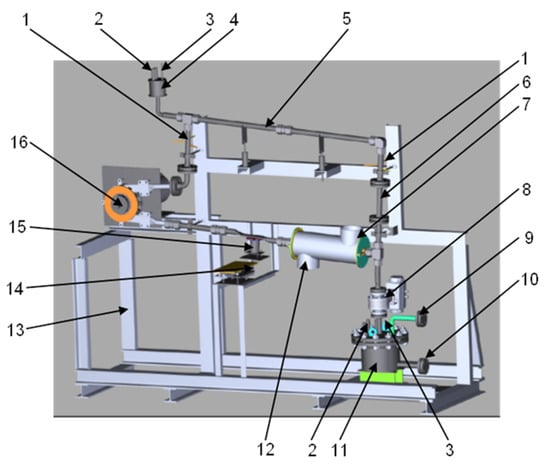
Figure 1.
3D sketch of the CiCLo-C facility.

Table 1.
Main components of the loop, as indicated in Figure 1.
The liquid metal loop has the main operating parameters indicated in Table 2. These parameters were selected considering the worst extreme conditions for a breeder blanket. Of course, it is possible to work in softer regimes and perform specific tests for less demanding scenarios.

Table 2.
Main features of CiCLo-C.
A permanent magnetic pump (PMP) from SAAS GmbH is responsible for the lithium lead circulation inside the loop. It has a rotor diameter of 250 mm, a power of 3 kW, and a rotation speed varying between 70 and 705 rev/min. It can work at up to 600 °C, and as visible from Figure 2, it can supply different flow rates at different working pressures. Thus, the PMP supplies a range of PbLi velocities in the TS from 0.2 m/s to 2.5 m/s.
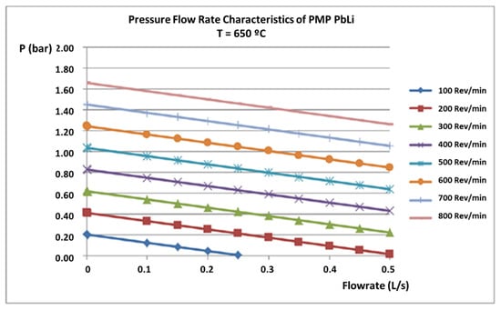
Figure 2.
Pressure vs. flow rate variation characteristic curves of the permanent magnetic pump, by SAAS GmbH.
The draining tank is responsible for recollecting all the liquid metal previously molted. It is provided by a cap and side hook because in this way, it can be removed directly with all the contaminated lead lithium once the experimental campaign is finished. For this purpose, the tank was designed with a slope at the bottom, which facilitates the evacuation of the liquid metal through a drain valve. This drain valve will also be used to extract samples of PbLi during the experimental campaign. With periodic analysis of the liquid metal, it will be possible to have an indirect measurement of how corrosion is acting and identify the presence of a small leak or any possible contamination. At the bottom, a rail system permits movement in the horizontal direction to compensate for the thermal expansion of the whole loop (see Figure 3). An additional expansion tank is placed at the top of the loop for filling purposes and to compensate for changes in the level of the liquid metal (Figure 1).
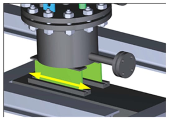
Figure 3.
Details of the rail system of the draining tank, which permits movement due to thermal expansion.
The flow meter is a magnetic flywheel one from SAAS GmbH and consists of three main components: mechanical, inductive proximity switch, and frequency and revolutions relay. It is described by the diagram in Figure 4a. The flow meter is powered by the fluid in the pipe situated above it. The rotation of the shaft is recorded by an inductive proximity switch and is subsequently analyzed by a frequency and rotation relay. For the use and calibration of this flow meter, is necessary to use a dedicated channel with a custom-made flat pipe (see Figure 4b). The magnets are made of SmCo alloy, and as the liquid metal flows, the magnet system rotates at a rotation speed proportional to the flow rate. The measurement can be read out in a voltage value range of 0–10 V or a current value range of 4–20 mA.
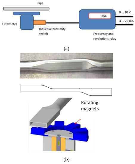
Figure 4.
Schematic description of the flow meter (a). Custom-made pipe in proximity to the flow meter (b).
Temperature measurements are monitored by the thermocouples NiCrNi type K along the entire loop in direct contact with the outer surface of the pipe. An additional temperature measurement is included inside the pipe with the help of three fingers at different depths: one before the test section and one after the pump. In this way, it is possible to measure the liquid metal temperature at different positions along the tube diameter, enabling possible variation in the thermal distribution along the depth of the tube to be measured and compared with the temperature measured by the external thermocouples. The thermocouples each have a diameter of 2 mm and are inserted into the sleeve end (see Figure 5).
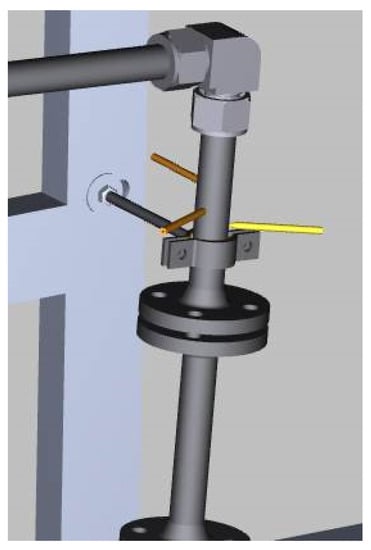
Figure 5.
Fluid temperature measurement system through three-point finger system.
Level detection is fundamental for the filling and draining stages of the loop. The sensors for level detection are inserted in the cap of both tanks (expansion and draining tanks). The level of liquid metal is measured by conductive probes. Their exact length must be determined during the commissioning of the loop. Commercial spark plugs are used as shown in Figure 6.
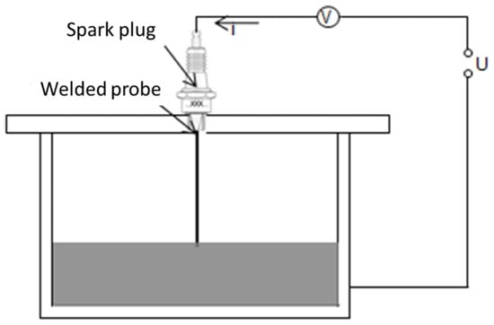
Figure 6.
Principle of conductive level detection.
For forced cooling, a controllable heat exchanger is a mobile part of the design. The transmission power of the heat exchanger was calculated for the working point of 550 °C in the liquid metal and is shown in Table 3. The heat exchanger can use approximately 1.25 kW to adjust the thermal balance of the loop.

Table 3.
Working parameters of heat exchanger design.
The loop heating is reached through several systems located in direct contact with the tube walls, ensuring uniform heating throughout the whole loop. Flexible, high-temperature heating tapes are used in the whole loop.
The PMP does not need a heater. Its channels are heated by the induction eddy currents inside the pump channel supplied by the magnet rotation, and its temperature is continuously controlled by K-type thermocouples. The cooling power transmission is 1.25 kW, which means that the maximum temperature of PbLi would be of 600 °C.
The electrical equipment is located in a cabinet and includes a touch panel for the control of the system programmed by the Siemens TIA Portal and WinCC Flexible. The electric device is designated for a 400 V/50 Hz TNS supply, and the nominal current per phase is 40 A.
The largest part of the electrical system is the control of the heating units, which can be activated and deactivated, measuring the current through a heating zone and detecting eventual failures, guaranteeing safety.
For the tanks, mineral-insulated band barrels from Watlow are used (700 W). Superwool Plus fiber from Morgan Advanced Materials is used as thermal insulation. This material (128 kg/m3, thermal conductivity 0.11 W/m·K at 500 °C) withstands temperatures up to 1200 °C.
The loop functioning starts with the melting of the lead lithium material and is described below.
The lead lithium is supplied in form of solid ingots, which are melted and purified in a special tank built for this purpose. The melting tank is located at the bottom of a glove box (GB) [35] and connected to the main tank of the loop by a pipeline with a small inclination that compels gravity filling. The vacuum-stored ingots are introduced inside the GB and opened in Ar atmosphere to avoid oxidation. Located inside the main tank, surrounded by band-barrel heaters, ingots are melted at 350 °C (melting point: 235 °C). Once totally heated, the first important step is represented by the purification of the melted material: all the impurities eventually present begin to float on the surface of the molten tank [11,35]. They are removed with extreme caution before starting the next phase: the filling of the loop draining tank.
A ball valve at the bottom of the molten tank opens the PbLi pass to the connection with the draining tank of the loop. Conductive probes located at different heights measure the PbLi level inside it, informing when the tank is starting to fill, half-filled, and completely filled. Once filled, the connection with the GB is closed, the loop is inertly insulated from the rest of the installations, and the second phase, loop filling, can be started.
The loop filling is performed with argon pressure; it is adjusted so that the liquid metal starts rising into the loop slowly. Three sensor levels inside the expansion tank are responsible for informing when the loop starts filling (the first one) and is completely filled (the second one). The third one is a safety sensor that has the important role of immediately draining the loop if it is activated by accidental overfilling.
The PbLi circulates in a clockwise direction at the selected velocity thanks to the PMP located in one of the corners of the circuit. The flow meter is installed just before the pump to allow the correct measurement of the flow before the liquid metal enters the PMP.
Finally, the entire loop, except the test section, will be internally coated with tantalum. The treatment is a gas phase process that is able to coat even surfaces with more complex geometries (e.g., fittings, elbows, and pump channels). All dimensions of the components are suitable to be chemically coated with tantalum. As a result, the stainless-steel tubes gain superb corrosion resistance of tantalum while maintaining the mechanical properties of stainless steel and thus enlarging the durability of the loop itself. Samples of 316 stainless steel covered by tantalum have already been produced and analyzed after several heating cycles, showing no signs of defects or distortions (Figure 7). An SEM microscopy image shows good adhesion with the substrate and uniform thickness. The extremely rugged, uniform, and the inert surface will ensure that all the corrosion impurities are only derived from the degradation of the samples in the test section.
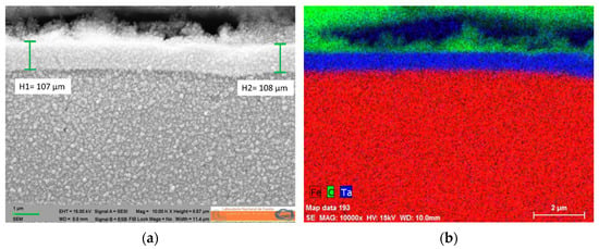
Figure 7.
SEM microscopy image of a 316 stainless steel sample covered by tantalum, showing good adhesion with the substrate and uniform thickness (a). Mapping EDX analysis of the coated sample (b).
3.2. Flow Meter Calibration
The flywheel is used to measure the liquid flow rate because the rotation speed, n, is proportional to the flow rate.
The calibration of the device is based on the thermal balance of the loop. The loop is adjusted to a stationary thermic state. The pump works according to a theoretical characteristic curve in an average rotation speed. All heating zones, except the horizontal one just after the PMP, are deactivated. By adjusting the heating in this zone and the cooling capacity of the coolant, just before the flow meter, a state is established in which all temperatures of the loop are constant. The temperature of the fluid shall be equal to the working temperature of the loop. The present volume flow is calculated with the following Equation [36]:
where is the volume flow rate, is the electrical power of the heaters, is the density depending on the fluid temperature (see Figure 8), is the specific heat capacity depending on the fluid temperature (see Figure 9), and are the fluid temperatures at the three-point temperature points: after the PMP and before the test section.
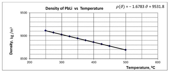
Figure 8.
Variation of PbLi density with temperature.
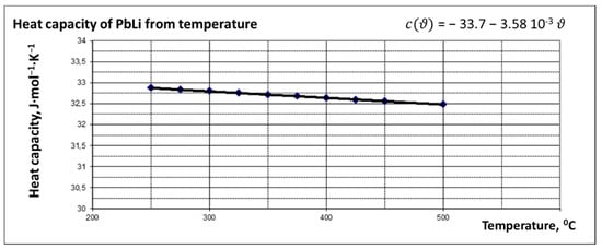
Figure 9.
Dependence of heat capacity of PbLi on temperature.
The measured rotation speed of the flow meter in this state can be related to the calculated flow rate. Thus, the linear characteristic curve of the flow meter using the zero point is calibrated and can be defined for the temperature measured at the thermocouple in the flow meter channel. To calculate the flow meter calibration for other temperatures in the device, the constant k must be determined by the balance between the accelerating and braking torque at the flywheel [36]:
where A is the cross-section of the flow channel, r is the radius of the flow meter (45 mm), is the rotation speed at the calibration temperature, is the electrical conductivity of the channel wall at the calibration temperature, and is the electrical conductivity of fluid at calibration temperature.
In both cases, the error is given by thermocouples, with a total uncertainty range of up to ±2–3% of the reading.
3.3. Test Section
In order to simulate the most realistic environment in terms of geometry, the TS was designed as a cylindrical tube, 176 mm long. All TS components follow this cylindrical configuration, as shown in Figure 10.

Figure 10.
Tubular test section with cylindrical EUROFER samples located inside a 316 L pipe.
Inside the main pipe, 10 samples in the form of rings and an extra piece to adapt the flow from the main pipe of the loop to the TS caudal, 32.8 × 8.5 × 16 mm3, are foreseen. Liquid metal enters from the top of the TS and flows down with a laminar flow rate. According to this direction, the first piece has a different shape in order to adapt the caudal smoothly from 32 mm outside of the TS to 15.8 mm inside the TS. The lower diameter of the TS assures the desired PbLi velocity by maintaining the rest of the circuit at a lower velocity, as can be seen in Table 4.

Table 4.
Comparison of the main operative parameters in the TS and the rest of the loop.
At the end of the TS, an extra piece is installed to contain the samples in the appropriate position even if the flow is swift.
This configuration of the test section provides an important new characteristic to the corrosion samples analyzed: the flow regime of the lead lithium in contact with the EUROFER will be uniform, as in the case of breeder blanket channels in a fusion reactor.
Considering that the extreme conditions that this new loop can achieve are also the most corrosive ones, the test section has been designed to ensure them only in this part, leaving the rest of the experiment to work in milder conditions.
In Table 4, the main operative parameters in the TS and in the rest of the loop are summarized.
As previously mentioned, the temperature in the TS can achieve 550 °C and a PbLi flow of 1 m/s. The experiment stops after running for 250, 500, 1000, 2000, and 4000 h in order to obtain the corrosion rate at different exposure times and evaluate the cinematic rules of the corrosion rate. When the pump stops running, the loop is drained by gravity to the main tank of the loop, where PbLi keeps its temperature over the melting point. Once the loop is totally drained, the test section is opened and manipulated in a glove box under an argon atmosphere. The loop is turned on again without changing the experimental conditions, and the dynamic of the flow does not change. The test section is reinstalled, and the loop is cleaned with argon to eliminate possible oxygen and filled up again.
On the other side, there is the possibility of introducing samples with different geometries from an additional port located just before the TS just described, in the elbow. In this way, it is possible to analyze samples with different geometries to test additional effects, such as hardening or embrittlement.
4. Conclusions
The CiCLo-C facility will study the corrosion mechanism on nuclear materials under the most realistic conditions according to the current breeding blanket concepts. An internal tantalum coating helps to prevent the corrosion of the pipes and main components, while a cylindrical test section can reproduce realistic hydraulic conditions in the blanket pipes. The flexibility of the system allows the installation of other test sections with different materials and different configurations for material compatibility studies. This facility provides unique features in the nuclear material study of corrosion effects and supplies the possibility of several upgrades in different fields (specific sensors, purification systems, magnetic field effect in corrosion, etc.) for a deeper analysis of corrosion phenomena. Finally, the main aims of this facility will be performing experiments simulating real reactor conditions, observing how corrosion could act after long cycles on structural materials, mixing its effect with that of oxidation, determining the possible presence of leaks, identifying the effects of corrosion on welding, determining how to act in the presence of a plug in the loop, and developing experience and manageability with security issues related to this liquid metal.
Author Contributions
Conceptualization, E.C. and D.R.; methodology, E.C. and D.R.; software, S.L.; validation, E.C., D.R. and S.L.; formal analysis, E.C.; investigation, E.C. and D.R.; data curation, E.C. and S.L.; writing—original draft preparation, E.C.; writing—review and editing, E.C. and D.R.; supervision, D.R.; project administration, D.R.; funding acquisition, E.C. and D.R. All authors have read and agreed to the published version of the manuscript.
Funding
This research was supported by the Madrid Community through the program TECHNOFUSION(II)-CM (S2013/MAE-2745) and by the HISMEFUS program (ENE2013–43650-R).
Institutional Review Board Statement
Not applicable.
Informed Consent Statement
Not applicable.
Data Availability Statement
Not applicable.
Conflicts of Interest
The authors declare no conflict of interest. The funders had no role in the design of the study; in the collection, analyses, or interpretation of data; in the writing of the manuscript, or in the decision to publish the results.
References
- Lindau, R.; Möslang, A.; Rieth, M.; Klimiankou, M.; Materna-Morris, E.; Alamo, A.; Tavassoli, A.-A.F.; Cayron, C.; Lancha, A.-M.; Fernandez, P.; et al. Present development status of EUROFER and ODS-EUROFER for application in blanket concepts. Fusion Eng. Des. 2005, 75–79, 989–996. [Google Scholar] [CrossRef]
- Boccaccini, L.V.; Aiello, G.; Aubert, J.; Bachmann, C.; Barrett, T.; Del Nevo, A.; Demange, D.; Forest, L.; Hernandez, F.; Norajitra, P.; et al. Objectives and status of EUROfusion DEMO blanket studies. Fusion Eng. Des. 2016, 109–111, 1199–1206. [Google Scholar] [CrossRef]
- Kovari, M.; Coleman, M.; Cristescu, I.; Smith, R. Tritium resources available for fusion reactors. Nucl. Fusion 2017, 58, 026010. [Google Scholar] [CrossRef]
- Carella, E.; Hernández, T.; Moreno, B.; Chinarro, E. Electrical behaviour of ceramic breeder blankets in pebble form after γ-radiation. Nucl. Mater. Energy 2015, 3–4, 1–5. [Google Scholar] [CrossRef]
- Palermo, I.; Fernández, I.; Rapisarda, D.; Ibarra, A. Neutronic analyses of the preliminary design of a DCLL blanket for the EUROfusion DEMO power plant. Fusion Eng. Des. 2016, 109–111, 13–19. [Google Scholar] [CrossRef]
- Casini, G.; Sannier, J. Research and development on liquid Pb-17Li breeder in Europe. J. Nucl. Mater. 1991, 179–181, 47–52. [Google Scholar] [CrossRef]
- Coen, V. Lithium-lead eutectic as breeding material in fusion reactors. J. Nucl. Mater. 1985, 133–134, 46–51. [Google Scholar] [CrossRef]
- Fernandez, P.; Lancha, A.M.; Lapena, J.; Serrano, M.; Hernandez-Mayoral, M. Reduced Activation Ferritic/Martensitic Steel Eurofer 97 as Possible Structural Material for Fusion Devices. Metallurgical Characterization on As-Received Condition and after Simulated Services Conditions; Centro de Investigaciones Energeticas: Madrid, Spain, 2004; Available online: http://inis.iaea.org/Search/search.aspx?orig_q=RN:36026402 (accessed on 20 January 2021).
- Tortorelli, P.F.; Chopra, O.K. Corrosion and compatibility considerations of liquid metals for fusion reactor applications. J. Nucl. Mater. 1981, 103, 621–632. [Google Scholar] [CrossRef]
- Chopra, O.K.; Tortorelli, P.F. Compatibility of materials for use in liquid-metal blankets of fusion reactors. J. Nucl. Mater. 1984, 123, 1201–1212. [Google Scholar] [CrossRef][Green Version]
- Smolentsev, S.; Li, F.-C.; Morley, N.; Ueki, Y.; Abdou, M.; Sketchley, T. Construction and initial operation of MHD PbLi facility at UCLA. Fusion Eng. Des. 2013, 88, 317–326. [Google Scholar] [CrossRef]
- Martelli, D.; Barone, G.; Tarantino, M.; Utili, M. Design of a new experimental loop and of a coolant purifying system for corrosion experiments on EUROFER samples in flowing Pb-Li environment. Fusion Eng. Design. 2017, 124, 1144–1149. [Google Scholar] [CrossRef]
- Huang, Q.; Zhang, M.; Zhu, Z.; Gao, S.; Wu, Y.; Li, Y.; Song, Y.; Li, C.; Kong, M. Corrosion experiment in the first liquid metal LiPb loop of China. Fusion Eng. Des. 2007, 82, 2655–2659. [Google Scholar] [CrossRef]
- Karditsas, P.; Caloutsis, A. Corrosion and activation in fusion cooling loops—TRACT. Fusion Eng. Des. 2007, 82, 2729–2733. [Google Scholar] [CrossRef]
- Kumar, M.; Patel, A.; Jaiswal, A.; Ranjan, A.; Mohanta, D.; Sahu, S.; Saraswat, A.; Rao, P.; Rao, T.S.; Mehta, V.; et al. Engineering design and development of lead lithium loop for thermo-fluid MHD studies. Fusion Eng. Des. 2019, 138, 1–5. [Google Scholar] [CrossRef]
- Zhu, Z.; Huang, Q.; Gao, S.; Song, Y.; Li, C.; Peng, L.; Chen, H.; Liu, S.; Ling, X.; Chen, Y.; et al. Design analysis of DRAGON-IV LiPb loop. Fusion Eng. Des. 2011, 86, 2666–2669. [Google Scholar] [CrossRef]
- Venturini, A.; Utili, M.; Gabriele, A.; Ricapito, I.; Malavasi, A.; Forgione, N. Experimental and RELAP5-3D results on IELLLO (Integrated European Lead Lithium LOop) operation. Fusion Eng. Des. 2017, 123, 143–147. [Google Scholar] [CrossRef]
- Zhang, M. Corrosion experiment for CLAM and SS316L in liquid LiPb loop of China. Ann. Nucl. Energy 2015, 80, 203–206. [Google Scholar] [CrossRef]
- Konys, J.; Krauss, W. Corrosion and precipitation effects in a forced-convection Pb–15.7Li loop. J. Nucl. Mater. 2013, 442, S576–S579. [Google Scholar] [CrossRef]
- Bucenieks, I.; Krishbergs, R.; Platacis, E.; Lipsbergs, G.; Shishko, A.; Zik, A.; Muktup, F. Investigation of corrosion effects of eurofer steel in Pb-17Li stationary flow in the magnetic field. Magnetohydrodynamics 2006, 42, 237–251. [Google Scholar]
- Rapisarda, D.; Fernandez, I.; Palermo, I.; Urgorri, F.R.; Maqueda, L.; Alonso, D.; Melichar, T.; Frýbort, O.; Vála, L.; Gonzalez, M.; et al. Status of the engineering activities carried out on the European DCLL. Fusion Eng. Des. 2017, 124, 876–881. [Google Scholar] [CrossRef]
- Gazquez, M.C.; Bassini, S.; Hernandez, T.; Utili, M. Al2O3 coating as barrier against corrosion in Pb-17Li. Fusion Eng. Des. 2017, 124, 837–840. [Google Scholar] [CrossRef]
- Hernández, T.; Sánchez, F.J.; Moroño, A.; Aristu, M.; Marco, J.F. Effect of irradiation on the stability of the corrosion layer produced in EUROFER by contact with lithium ceramics. J. Nucl. Mater. 2021, 545, 152614. [Google Scholar] [CrossRef]
- Konys, J.; Krauss, W.; Steiner, H.; Novotny, J.; Skrypnik, A. Flow rate dependent corrosion behavior of Eurofer steel in Pb–15.7Li. J. Nucl. Mater. 2011, 417, 1191–1194. [Google Scholar] [CrossRef]
- Garcinuño, B.; Rapisarda, D.; Fernández, I.; Moreno, C.; Palermo, I.; Ibarra, Á. Design of a permeator against vacuum for tritium extraction from eutectic lithium-lead in a DCLL DEMO. Fusion Eng. Des. 2017, 117, 226–231. [Google Scholar] [CrossRef]
- Garcinuño, B.; Rapisarda, D.; Moreno, C.; Sanz, J.; Ibarra, Á. Design of a System for Hydrogen isotopes Injection into Lead-Lithium. Fusion Eng. Des. 2018, 137, 427–434. [Google Scholar] [CrossRef]
- Smolentsev, S.; Saedi, S.; Malang, S.; Abdou, M. Numerical study of corrosion of ferritic/martensitic steels in the flowing PbLi with and without a magnetic field. J. Nucl. Mater. 2013, 432, 294–304. [Google Scholar] [CrossRef]
- Precipitation Phenomena during Corrosion Testing in Forced-Convection Pb-15.7Li Loop PICOLO | Elsevier Enhanced Reader. Available online: https://www.sciencedirect.com/science/article/abs/pii/S0920379619303564 (accessed on 2 February 2022).
- Corrosion Properties | Tantaline® Surface Treatment. Tantaline®. Available online: https://tantaline.com/technology/corrosion-properties/ (accessed on 2 February 2022).
- Muñoz, P.; Malo, M.; Moroño, A.; García-Cortés, I.; Cabrera, S. RIPER: An irradiation facility to test Radiation Induced Permeation and release of deuterium for fusion blanket materials. Fusion Eng. Des. 2019, 145, 66–71. [Google Scholar] [CrossRef]
- Electron Accelerator | Laboratorio Nacional de Fusión. Available online: http://www.fusion.ciemat.es/competitive-access-to-facilities/electron-accelerator/ (accessed on 2 February 2022).
- González de Vicente, S.M.; Boutard, J.-L.; Zinkle, S.J.; Tanigawa, H. Materials testing facilities and programmes for fission and ion implantation damage. Nucl. Fusion 2017, 57, 092011. [Google Scholar] [CrossRef]
- Konys, J.; Krauss, W.; Zhu, Z.; Huang, Q. Comparison of corrosion behavior of EUROFER and CLAM steels in flowing Pb–15.7Li. J. Nucl. Mater. 2014, 455, 491–495. [Google Scholar] [CrossRef]
- Abánades, A.; García, A.; Casal, N.; Perlado, J.M.; Ibarra, A. Conceptual design of the liquid metal laboratory of the TECHNOFUSION facility. Fusion Eng. Des. 2012, 87, 161–166. [Google Scholar] [CrossRef][Green Version]
- Garcinuño, B.; Rapisarda, D.; Fernández-Berceruelo, I.; Carella, E.; Sanz, J. The CIEMAT LiPb Loop Permeation Experiment. Fusion Eng. Des. 2019, 146, 1228–1232. [Google Scholar] [CrossRef]
- Lenk, S. Theory of Flywheel V7 2019. Available online: https://saasonline.de/en/measure/ (accessed on 2 February 2022).
Publisher’s Note: MDPI stays neutral with regard to jurisdictional claims in published maps and institutional affiliations. |
© 2022 by the authors. Licensee MDPI, Basel, Switzerland. This article is an open access article distributed under the terms and conditions of the Creative Commons Attribution (CC BY) license (https://creativecommons.org/licenses/by/4.0/).