Article

A Model-Based Approach for Common Representation and Description of Robotics Software Architectures

by
Valery Marcial Monthe
1,*,
Laurent Nana
2 and
Georges Edouard Kouamou
3
1
Faculty of Sciences, University of Yaounde 1, Yaounde P.O. Box 812, Cameroon
2
Lab-STICC, UMR CNRS 6285, University of Brest, P.O. Box 29238 Brest, France
3
National Advance School of Engineering, Yaounde P.O. Box 337, Cameroon
*
Author to whom correspondence should be addressed.
Appl. Sci. 2022, 12(6), 2982; https://doi.org/10.3390/app12062982
Submission received: 7 December 2021 / Revised: 15 February 2022 / Accepted: 17 February 2022 / Published: 15 March 2022
(This article belongs to the Special Issue Application of Computer Science in Mobile Robots)

Abstract

:
Unlike conventional software, robotic software suffers from a lack of methods and processes that could systematize and facilitate development. Thus, the application of software engineering techniques is at the heart of current issues in robotics. The work presented in this paper aims to facilitate the development of robotic software and to facilitate communication between experts in the field through the use of software engineering techniques and methods. It proposes RsaML (Robotic Software Architecture Modeling Language), a Domain Specific Modeling Language (DSML) dedicated to robotics, which takes into account the different categories of robotic software architectures and makes it possible to describe the latter independently from the implementation platform. The conceptual model defining the terminology and the hierarchy of concepts used for the description and representation of robotic software architectures in RsaML are presented in this article. RsaML is defined through a meta-model which represents the abstract syntax of the language. The real-time properties of robotic software architectures are identified and included in the meta-model. The use of RsaML is illustrated through several experimental scenarios of the language: the definition of a robotic system and the description of its software architecture, the verification of the semantics of a robotic software architecture, and the modeling of a robotic system whose software architecture does not belong to the usual categories. The support tool used for implementations and experimentation is Eclipse Modeling Framework (EMF). The results of experimentation showed good working of the proposed solution and made it possible to validate the main concepts of the RsaML language.

1. Introduction

Robotic systems are real-time systems whose behavior, of type “perception, decision, action”, is founded on information extracted from the environment with the help of sensors (for example, images captured by a camera). The information provided by the sensors should be processed within a bounded time interval in order to provide a new command to the robot, before the capture of new data.
Robotic systems are generally composed of two parts: a material part and an immaterial part. The material part contains the physical elements of the robot. The immaterial part contains the knowledge (programs) that allow the robot to operate in a complex, dynamic, and unstructured environment, and that affects its behavior [1]. This second part is called the control system of the robot. The control system can be completely embedded in the robot. It can also be split into two sub-parts: a remote sub-part and a sub-part embedded in the robot. The control system comprises control software system as well as other automated control processes. This paper focuses mainly on control software systems of robots. This software part has an architecture that is considered as the software architecture of the robotic system.
The software integration of the robot’s functionalities, which for a long time has been the hidden face of robotics, has become a central issue for the future robotic service industry (medical, assistance, etc.). Due to the increasing complexity of robotic systems and the ever-increasing diversity of applications and missions of robots, the design and development of performing and correct robotic software architectures has become a major issue [2]. The progress of the software industry has opened new opportunities and made the application of software engineering one of the main research areas in the robotics field, as shown by the important number of recent research works carried out on the development of robotic software ([3,4,5,6,7,8,9,10,11,12,13,14,15,16,17], etc.). One of the challenges of robotics today is to use techniques, tools, and methods that are proven in the development of “traditional” software systems to increase productivity in the development of robotic systems while ensuring the quality of their software architecture. The proposals [18] in this field aim to define methods, making it possible to describe and encapsulate the various functions of the robot in the form of a set of interactive software entities(function, class, module, components, etc.). The goal is to provide a solution for the design of robotic software that satisfies properties of modularity, portability, reusability, maintainability, etc. Describing the robotic software architecture is not enough. Indeed, it must be implemented, deployed, and executed in order to be fully used. Implementing the robotic software architecture and deploying it on an execution target, while controlling the logical and temporal constraints of the robotic system, requires the constraints coming from the underlying platform (hardware, operating system, and programming languages) to be taken into account. Building sustainable, reusable, and adaptable architectures for a wide variety of physical platforms and components (sensors and actuators, but also processors, networks, and other hardware sometimes specific to robotics) is a significant challenge [2]. In order to meet the aforementioned challenges, robotics is currently facing a fundamental question: How can we develop standardized and understandable control architectures that can capitalize designers’ knowledge and best practices, and which are based on reliable, composable, and reusable software entities, thus leading to optimization of time and development costs?
To answer this question, one needs to respond to several other questions:
  • How can we capitalize know-how in terms of architectural design?
  • How can we describe and encapsulate the functions of the robot in the form of software entities?
  • With which paradigm should these software entities be represented in order to facilitate their use and reuse?
  • Which formalism should be adopted to provide a standard representation of robotic software architectures? Which languages should be used to specify the conceptual model of these architectures? Generalist languages? Or languages that are specific to this field?
  • At which level of abstraction should we reason to guarantee the independence of architectures described with respect to technologies, and thus facilitate their reuse and possibly reduce a system’s development cost?
  • How can we build tools making it possible to quickly define these architectures and validate them at the design stage (upstream validation)?
A correct application and rigorous monitoring of the different steps of the software engineering development process (see Figure 1) to the construction of robotic software architectures could help to answer these questions. Nevertheless, such application requires investigating and proposing solutions adapted to the robotic domain at the different levels (expression of need, detailed design, etc.).
This paper, therefore, aims at proposing answers to the above questions of roboticists, by proposing software engineering solutions adapted to the robotic field and following the software engineering process. It focuses on the design step of the software engineering process and, more precisely, on the investigation and proposal of RsaML, a DSML for the robotic domain that makes it possible to facilitate the design of robotic software architectures satisfying software engineering principles (modularity, reusability, scalability, portability, maintainability, etc.).
The remainder of the paper is organized as follows. The second section is dedicated to the literature review. The third section deals with the RsaML language. The fourth section presents the experimentation of RsaML on a sample robotic system. A discussion is presented in the fifth section. The paper ends by conclusions and future works in the sixth section.

2. Literature Review

In this section, we first introduce some notions useful for a better understanding of the work presented in this paper, namely notions related to robotics software architectures and model-driven engineering, then we present related works.

2.1. Background

2.1.1. Overview of Robotic Software Architectures

Robotic software architectures can be classified into four categories: (i) traditional centralized architectures, (ii) hierarchical architectures, (iii) behavioral or reactive architectures and (iv) hybrid architectures. These different categories are briefly described hereafter.
  • Centralized architectures
    The first work on robotic control architectures belongs to the centralized architectures’ category. Centralized architectures were inspired from artificial intelligence, that is, organized around decision making and a symbolic state of the world and the robot [19,20]. These architectures place planning at the system’s center and share the axiom according to which the central problem in robotics is cognition, that is to say, the manipulation of symbols to maintain and act on a model of the world. The world is the environment with which the robot interacts. Among centralized architectures, we can mention the planning system STRIPS [19] which assumes that the plan remains static and the world is unchanged during its execution, and Blackboard architecture, ref. [21] which gathers information on a world that is assumed non static and takes decisions based on the world state and goals that could evolve during mission execution. Other examples of centralized architectures can be found in [22].  
  • Hierarchical architectures
    The organizational model of hierarchical architectures, also called deliberative architectures, centers the design over the decisional system [19,20]. These architectures are organized in several hierarchical layers (also called Levels) [21,23,24]. A layer only communicates directly with the levels immediately above and below itself. It breaks down a task, recommended to it by the immediately higher level, into more simple tasks for the immediately lower layer. The highest level manages the overall objectives of the application, while the lowest controls the robot’s actuators [20]. These architectures typically have three layers: functional (contains the perception modules), executive (in charge of the supervision of robot’s tasks execution), and decisional (in charge of planning). In this category of architectures, we can mention the following examples: NASREM (NASA Standard Reference Model) [25], the LIFIA architecture [26], the architecture Smach of I3S (Computer Science, Signals, and Systems Sophia Antipolis) [27], and FLEXHRC+ architecture, designed to provide collaborative robots with more autonomy when helping operators in shop-floor tasks that have large variability [28].  
  • Behavioral or reactive architectures
    In a reactive architecture [29], several modules connect the sensor inputs to the actuators. Each module implements a behavior, i.e., a basic functionality of the robot associating each input vector (the set of sensor values) to an output vector applied to the actuators. These behaviors are called “reactive” because they immediately provide an output value from a value in their entry. Inspired by observing animals’ behavior, these architectures are built according to the idea that a more mature behavior can emerge from a combination of a set of simple, basic behaviors.
    Subsumption architecture was the first behavioral architecture [29]. It was proposed by Brooks in the middle of the 1980s. Based on Brooks’ subsumption architecture, Rosenblat [30] proposed a new behavioral architecture called DAMN (Distributed Architectures for Mobile Navigation). Martín recently proposed an evolution of a behavior-based architecture developed at the Universities of Leon and Rey Juan Carlos [31]. This architecture takes into account the need for modular decomposition as well as the need for frequent reconfigurations to adapt to different competitions such as RoboCup Soccer and European Robotics League. It has been experimented with different robots, such as the four legged Aibo robot, the bipedal robot Nao, and wheeled robots TIAGo and RB1.  
  • Hybrid architectures
    Hybrid architectures combine the reactive capacity of behavioral architectures and reasoning skills (decisional) of hierarchical architectures [19,20]. These architectures include a hierarchy of layers and reactive nested loops, allowing each layer to provide responses tailored to its dynamics. Among hybrid architectures, we can mention The CONTROLSHELL [32]; LAAS architecture [33], which proved effective in the fields of mobile robotics both on the HILARE platform and in the MARTHA experiment; the ORCCAD architecture (Open Robot Controller Computer Aided Design System) of INRIA [34,35] that integrated formal verification of missions at the early steps of its design; The IDEA architecture (Intelligent Distributed Execution architecture) [19]; CLARATy (Coupled Layer aRchitecture for Robotic Autonomy) [36,37]; the architecture of the ISTL (Higher Technical Institute of Lisbon) [38]; and the Autonomous Robot Architecture (AuRA) [39].
As mentioned earlier, one of the challenges of robotics today is to use well-known and proven software engineering techniques for the development of software dedicated to robots. In the next subsection, we present an overview of MDE, a software engineering technique, that we have chosen in this perspective. MDE has proven its efficiency in the development of traditional software systems.

2.1.2. Model-Driven Engineering

MDE technology combines [40] domain specific modeling languages (DSML), the ability to describe constraints on DSML, transformation engines, and support tools. In this section, we present this technology as well as the concepts related to DSML, an example of language dedicated to the definition of constraints, and a framework that supports the implementation of the MDE technology.

Brief Presentation of MDE

A model is an abstraction, a simplification of a system that allows to understand and answer the questions asked about the latter. A system can be described by different models related to each other. Model is at the heart of MDE technology, which combines two major activities:
  • The meta-modeling, which aims at building a model called meta-model that makes it possible to define models description languages, i.e., modeling languages. The meta-modeling enables the definition of a modeling language for a domain, also called Domain Specific Modeling Language (DSML), through the definition of domain concepts, relationships between these concepts, and specific constraints required by the domain.
  • The model transformation that aims to build processing engines, enabling movement from one model to another and the creation of operational models (for code generation, documentation, testing, verification, implementation, etc.) [41].
MDE has several significant improvements in the development of complex systems, allowing us to focus on a more abstract concern than conventional programming. This is a form of generative engineering in which all or part of an application is generated from models [41].
The benefits of MDE are many: independence from technological changes, better management of complexity, greater reusability, etc. The number of views increases, the models used and their associated semantics are becoming better defined and, little by little, models occupy a central position in the development process: the virtual prototype of the system to achieve. Indeed, the evolution of software workshops (such as I-Logix Rapsody, and Artisan Software Studio) and languages allows executable model building today [42]. Meta-models have significant advantages over other techniques, such as BNF grammars or the UML profile [43].

Domain Specific Modeling Languages (DSML)

DSMLs are languages that are designed on purpose for a specific domain, context, or company, to ease the task of people that need to describe things in that domain [44]. They are particularly useful because they are tailored to the requirements of the domain, both in terms of semantics and expressive power (and thus do not force end users to study more general-purpose languages that may be full of concepts completely irrelevant for the domain) and of notation and syntax (and thus provide appropriate modeling abstractions and primitives closer to the ones used in the domain). A modeling language is defined through three core ingredients. (i) Abstract syntax: Describing the structure of the language and the way the different primitives can be combined together, independently of any particular representation or encoding; (ii) Concrete syntax: Describing specific representations of the modeling language. It consists of one or more diagrams. The concrete syntax can be either textual or graphical; and (iii) Semantics: Describing the meaning of the elements defined in the language and the meaning of the different ways of combining them.

OCL: A Language for Verification of UML Models

OCL (Object Constraint Language) is a functional language based on first-order logic for expressing specifications on a UML model. By the representation of different types of UML diagrams in the form of class diagrams, OCL can be used as the meta-model specification language, which requires a good knowledge of the syntax and semantics of modeling elements. OCL rules may be attached to a meta-model not only to check the own semantic rules of the modeled domain, but also to restrict the set of valid instances (models). OCL allows navigation in class diagrams (particularly in the meta-model) and has set-primitive and iterators on data collections. One can thus express the pre- and post-conditions of methods, class invariants, etc. [45].

Overview of Eclipse Modeling Framework (EMF)

The choice of a meta-modeling technology depends primarily on the availability of tools to support the development of a complete solution. The Eclipse Modeling Framework (EMF) [26] is the leading open-source tool in this area. It provides enhanced support for graphical and textual notations modeling languages and for validating model constraints, the model to model and the model to text transformations. The various tools of this framework follow the standards of the Object Management Group (OMG) [46,47,48]. EMF provides code generation capabilities, allowing us to define a model either in UML, XML, or Java form, and to generate the other forms from this latter as well as the corresponding implementations classes. Regardless of the technology used to define a model, EMF is the common high-level representation that “gathers” them all together [49]. EMF models are usually represented with the help of a UML class diagram notation [50]. However, in contrast to models created in UML, models created with meta-modeling solutions are formal and precise [51]. These models are Ecore models that represent the abstract syntax of the language defined for a given domain. EMF will then be used to generate a model from ecore (an XMI model) that represents the concrete syntax.

2.2. Related Work

In the last few years, more and more solutions for the use of software engineering techniques in robotics are proposed at different levels. We present some of them.
In [52], Passama proposes a solution to the problem of representation and communication of Robotic software architectures between domain experts. He proposes a specific modeling language for the domain, with the aim to express and easily compare different architectures.
In [53], Xavier Blanc et al. address the benefits brought by the MDE (Model Driven Engineering) approach to the development of embedded systems and robotics. They apply this approach to develop a software system for the Aibo robot.
The authors of [54] address the issue of model driven engineering applied to the design of a service robot controller. They develop a scalable modeling approach for the development of real-time control software of a prototype of seven-axis arm actuated by artificial muscles.
In [55], authors also address the issue of MDE process for robotic systems. They are particularly concerned with taking into account of non-functional properties in modeling properties such as quality of service and management of real-time resources (e.g., the schedulability analysis of real-time tasks).
The work proposed in [56] uses an MDE approach to design specific domain solutions for the development of robots control systems, using subsumption architecture. It presents a case study of the entire process: identification of domain meta-model, definition of graphic notation, and code generation.
The authors of [1,57] formulate the problem of the development of stable software systems in the robotics field, analyze the elements that make this problem difficult, and identify challenges that robotics community must face in order to build stable software systems.
In [58], authors present the contributions of model driven approach compared to code driven approach in the development of robotic software systems.
In [18], the authors propose an overview of Model Driven Engineering approaches in robotics. They point out the complexity of robots development due to the variety of hardware and software components and the lack of common standards.
The PuRSUE (Planner for RobotS in Uncontrollable Environments) approach defined in [59] aims to support developers in the rigorous and systematic design of high-level execution control strategies for robotic applications.
In [60], the authors provide a catalog of 22 mission specification models for mobile robots, as well as tools to instantiate them to create robotic mission specifications.
The work carried out in [61] provides an end-to-end overview of how robotic software systems can be formally specified from requirements modeling to architecture modeling, and from the latter to executable code generation.
The above works are related to a general application of MDE to robotics. Other works, such as those presented in [62], targeted more specifically the development of DSML for robotics. Hereafter, we briefly present SmartSoft [63] and RobotML [64], that are among the most recent.
SmartSoft is a component-based framework for robotic software that focuses on the communication model between components. It offers a predefined set of generic communication patterns based on standard communication services (client/server, master/slave, request/response, etc.) that the user can compose to build components. It allows the implementation of systems based on standardized components, whose interaction can be adjusted according to the context and current requirements. It builds on a meta-model called SmartMars [55] implemented as a UML profile, and was used as a basis for building an integrated Eclipse tool called SmartMDSD [65]. The latter provides an integrated development environment for robotic software using a model-driven approach and generates code to CORBA [66] and ACE [67].
RobotML is a language specific to the field of robotics, supported by a tool-chain to facilitate the design, simulation, and deployment of robotic applications on different target execution platforms. RobotML and its tool-chain were developed in the framework of the PROTEUS project (Platform for Robotics Organizing Transfer between Users and Scientists) [68]. It allows specifying the architecture of a robotic system (components, ports, and data types exchanged), the communication between the components through ports (flow of data or service) and their type (synchronous or asynchronous), the behavior of components through state machines or algorithms, and a deployment plan that defines several heterogeneous target platforms (simulators and middleware). RobotML is supported by a graphical editor designed using the Papyrus tool.
Analysis of the works summarized above allows us to identify a number of key points. Some of these works apply MDE only to a particular architecture or a particular robot. The management of functional constraints that cannot be addressed using graphical relationships between concepts is hardly addressed by these works. Likewise, very few of them deal with non-functional constraints. Additionally, among the works related to the definition of a DSML, only a few offer the possibility to describe the behavior of the components of an architecture. This does not facilitate information sharing on the architectures thus defined. Indeed, being able to describe the behavior of a component makes it possible to better guarantee its compositionality with other components and its reusability. Apart from the type of task (periodic, aperiodic) defined in one of the proposals, none of the works are able to specify real-time properties of the modeled systems.
After this overview of related works, the next section is devoted to the definition of RsaML, which has been proposed in order to remedy shortcomings observed in the existing solutions regarding the specification of non-functional constraints, the description of components behaviors, specification of real-time constraints, and description of functional constraints that cannot be handled graphically.

3. The New Domain Specific Modeling Language Proposed

In this section we first present the design approach adopted for the definition of the new DSML RsaML, then we present the different design steps: domain analysis; proposal of an abstract model of the language, semantics definition, constraints and real-time properties support, and definition of a concrete syntax of the language. An implementation of the abstract syntax with the integration of constraints properties is also presented to illustrate their working.

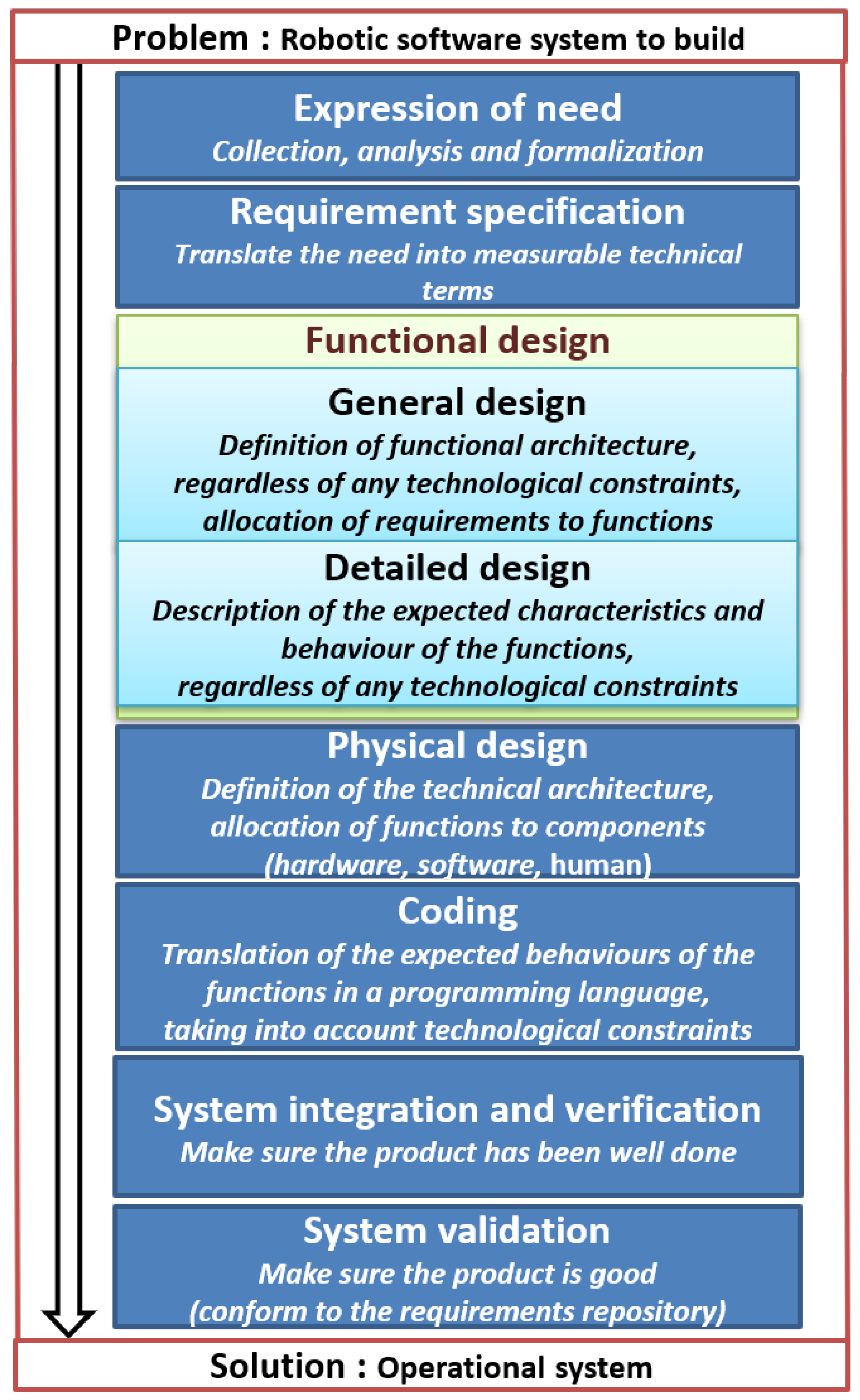
3.1. Design Approach

The development of a domain specific modeling language begins with the identification of modeling concepts. This requires one to understand the functioning of the field and the notions which are used in the domain, how to use them, and the links between them. In our case we relied on reference documents (original publications) of each class of architectures as well as publications in the field. Different concepts are used in each category. Thus, the main design steps and challenges are to: (i) define concepts which allow us to represent any robotic software architecture; (ii) define the types of these concepts in the model, the relationship between them, and especially cardinality, which allows us to implement structural and functional aspects of these architectures; (iii) be concise, but accurate and complete, to avoid proposing a model that is dense and therefore complex, which may be difficult to analyze and understand for end users of the language; (iv) provide the opportunity to define the real-time properties in the models that will be built.

3.2. Domain Analysis: The Main Modeling Concepts

This activity aimed to:
  • Identify the notions handled in the categories and examples of architectures;
  • To abstract and define the resulting concepts, their properties, and the relations between them;
  • Analyze the real-time properties handled in the domain and their context of use;
  • Organize these concepts in a hierarchy.
To do this, a careful study of each robotics software architecture class was made, followed by a synthesis of the concepts handled. This initial work resulted in a list of concepts per architecture. Thereafter, all the concepts were integrated into a single set of concepts comprising all the concepts of all the classes of architectures. Once identified, each concept was described based on the concept of robotics it models. Table 1 shows in alphabetical order some of these descriptions.
Table 1 presents in its left column the different concepts used to specify robotic software architectures and in the right column a brief meaning of each concept.
For a better understanding and ease of use of the concepts in the language, a hierarchy of all the concepts has been built. The diagram in Figure 2 shows the hierarchy of the different concepts identified.
This hierarchy can be described as follows. A robotic system consists of a robot, the environment in which it operates, and the software that controls it. A robot has a central part which we call the “body of the robot” and a set of hardware components. The software allows the robot to evolve in its environment (set of physical and logical resources). The hardware components can be either sensors, actuators, or any other device for communicating and evolving (observation, perception, and reaction) in its environment. The software consists of a set of decision-making components (layer, activity, database, knowledge, etc.) and behavioral components (action, function, module, modifier, goal, etc.). There are two types (small empty triangle in the figure) of ports: input ports and output ports. In some architectures, such as subsumption, the port data can be modified by those of another. Thus, an input port can carry multiple suppressors and an output port several inhibitors. The multiplicity [1..*] on the relationship between the elements Software and Software Component for example, means that a software is composed (small black diamond) of one or more software components.
After this presentation of the main concepts used in robotics software architectures, the next subsection deals with the use of these concepts to define an abstract syntax for the Domain Specific Modeling Language RsaML.

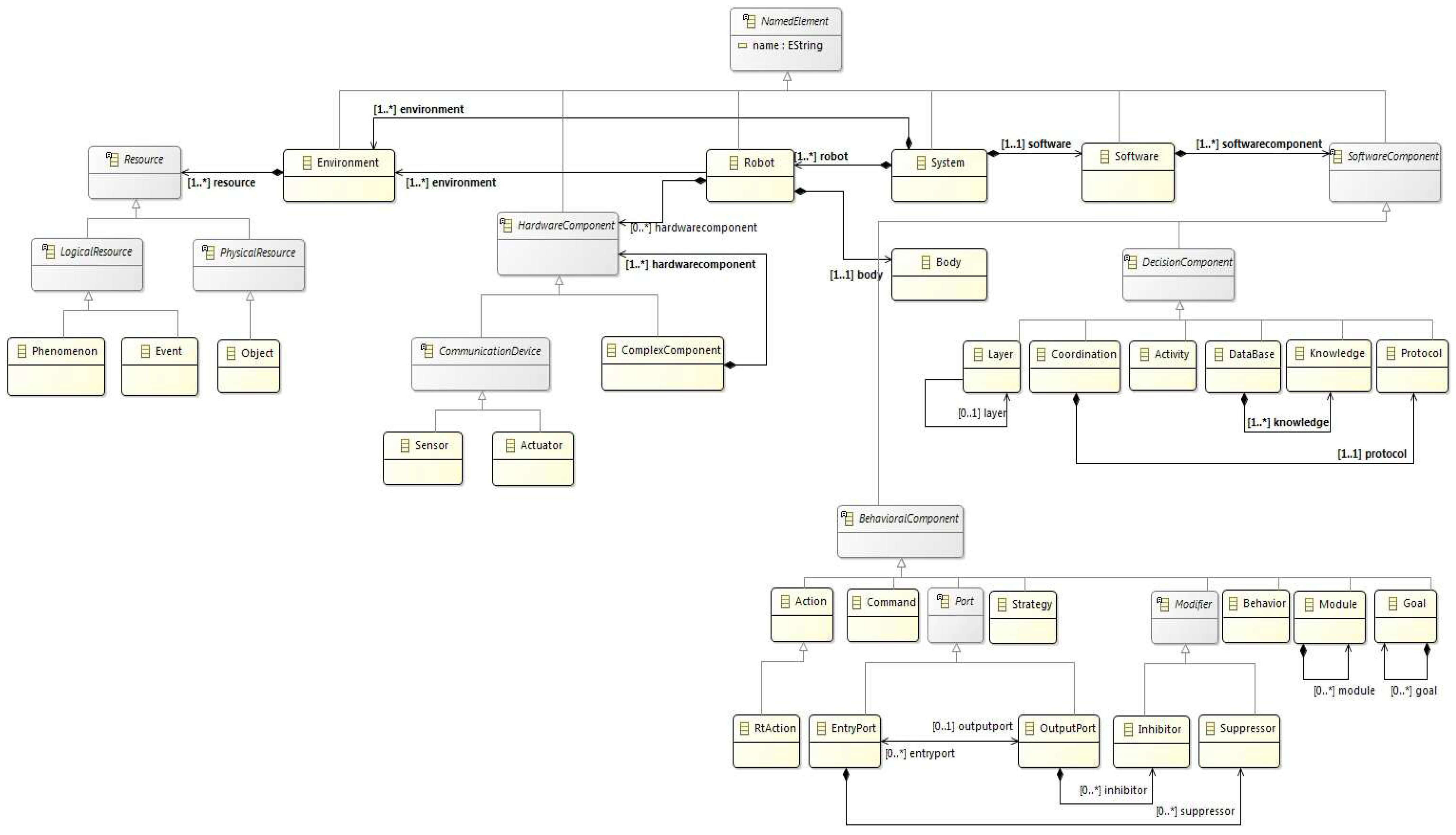
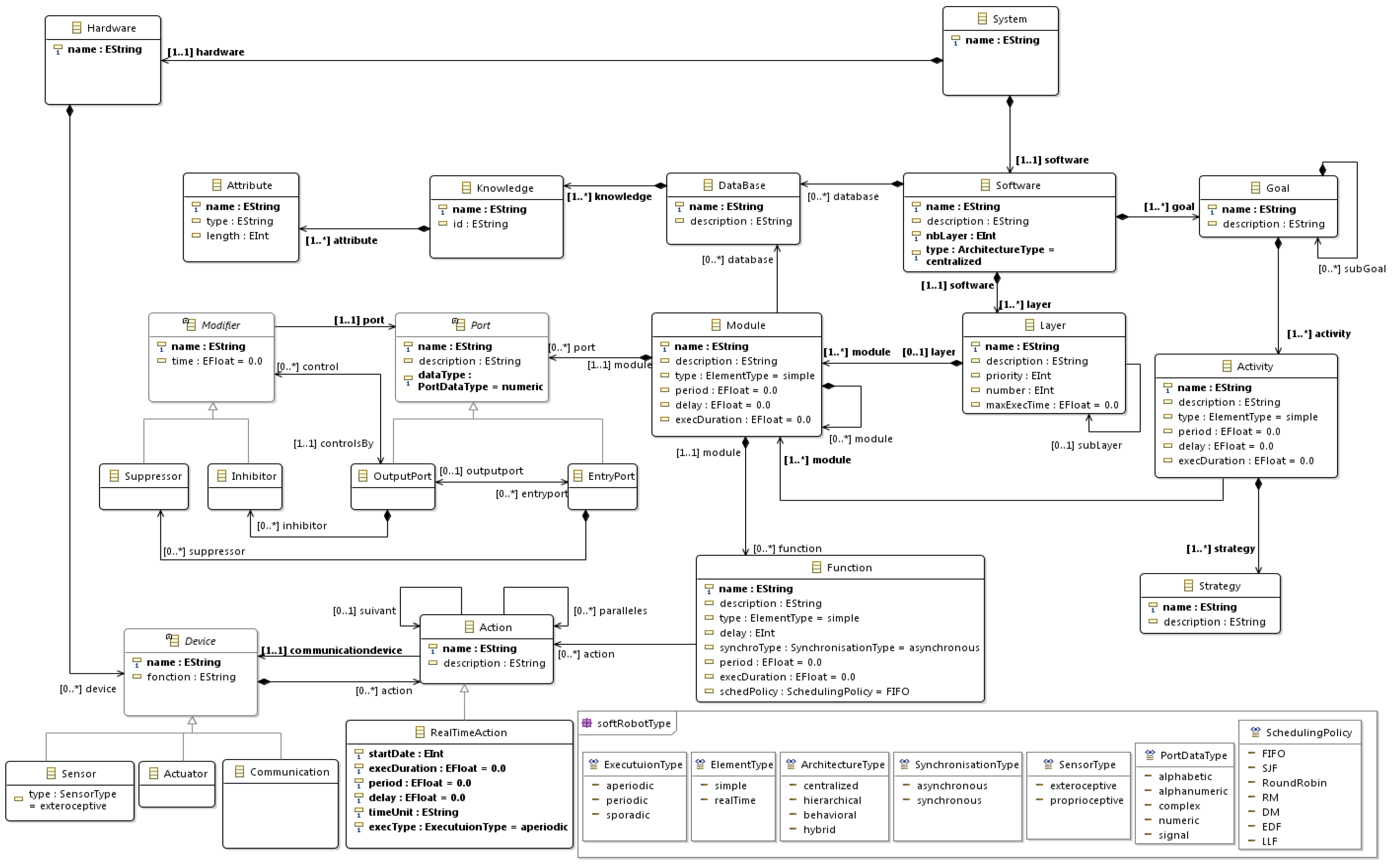
3.3. Abstract Syntax of RsaML: The Proposed Meta-Model

The abstract syntax of RsaML is defined through a meta-model, which shows the way in which the concepts identified in robotic software architectures are put in relationships to define an architecture. This meta-model was built using Ecore meta-meta-model. It is shown in Figure 3.
The diagram in Figure 3 can be described as follows: a robotic control software can be composed of a database containing a set of knowledge and several layers, and must have one or more goals to achieve. The goal can be broken down into sub goals reached by performing a set of activities. These activities follow a given strategy. The activities are carried out by execution of processes that are implemented in modules. The modules that are on the layers may have several functions that implement processing. The modules communicate through ports. Each function is a set of actions that can be simple or contain real-time constraints (real-time action). An action can be followed sequentially by another or run in parallel to several others.
Generally, the abstract syntax of the DSML does not have enough information to define the meaning of the constructs of the latter. Additional information is needed to determine this meaning. This is achieved through the semantics of the language. There are two types of semantics: static semantics and dynamic semantics. In this paper, we focus on the static semantic. It is defined at two levels:
  • When defining the meta-model, by defining the multiplicities of the relations between the concepts;
  • By defining and integrating semantic constraints to the meta-model. This is the purpose of the next section.

3.4. RsaML Semantics: Definition of Constraints on the Meta-Model

The definition of RsaML semantics requires us to identify and organize information which make it possible to give a meaning (in relation with the field of robotics) to the built models, then to define the latter as semantic rules of RsaML. After defining the semantic rules, a solution is needed for their integration in the meta-model. Although constraints such as the multiplicities of relations between the concepts can be directly included in the graphical model, the other semantic constraints are generally defined using a textual approach. In this work, OCL is used for the definition of these additional semantic constraints. It is a well known standard for textual constraints definition which is commonly used in MDE.
This subsection is structured in two parts: the first presents some defined semantic rules and the second presents the OCL constraints defined for their integration in the meta-model.

3.4.1. Definition of Semantic Rules

Using the operating principle of the different categories and examples of architectures, we have identified and defined semantic rules. Some of them are presented below.
There are rules related to the general operation of architectures among which:
  • The number of declared layers must be equal to the number of layers actually in the system.
  • Two communicating modules must exchange the same type of data on their communication interfaces.
  • A module only communicates with modules that are either on the same layer as it, or on the layer directly above or directly below.
  • For some architectures in the category of behavioral architectures, a module can inhibit (or delete) only the outputs (resp inputs) of the modules of the immediately lower layer.
And specific rules regarding real-time aspects, such as the following:
  • If the type of a module is real-time, its period and delay must be non-zero.
  • A module is real-time if all its functions are real-time.
  • A function is real time if all its actions are real-time.
  • Runtimes of all the modules of a layer are bound by the maximum execution time of the layer.

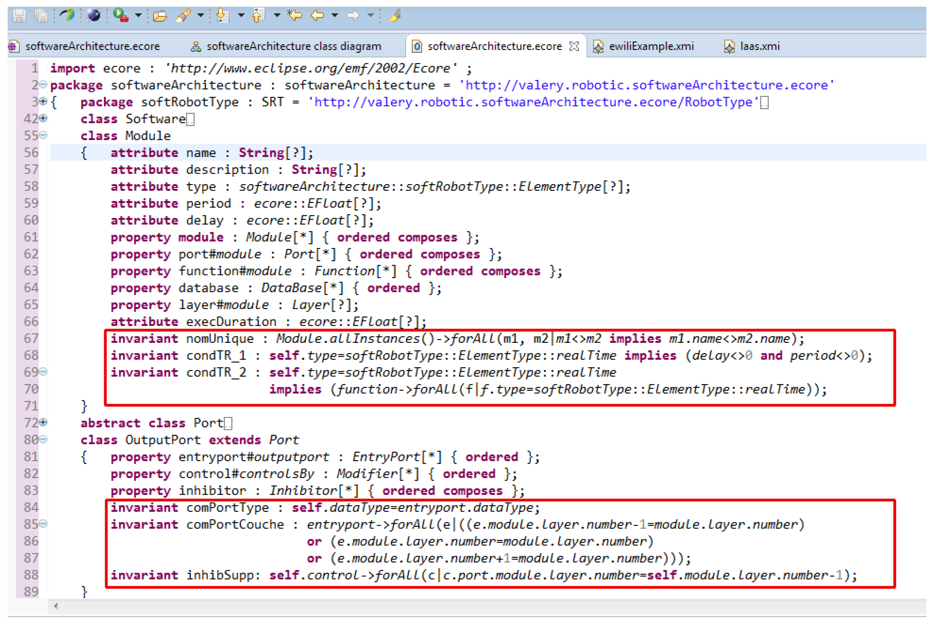
3.4.2. Defining OCL Constraints to Check Semantic Rules

In order to integrate the semantic rules of RsaML in the meta-model (abstract syntax) of RsaML, these rules are translated into OCL constraints. These last serve as rules of good formation of models. Some of the OCL constraints are presented in Listing 1. Each time, the constraint in natural language is given in the form of a comment, followed by the OCL code (context and invariant) corresponding to its definition.
Listing 1. Some OCL constraints imposed on the domain’s meta-model.
  • --1. Each system has a name and at least one layer
  • context Software
  • inv : name<>“‘‘ and layer->size()>0
  • --2. The number of a layer is always less than the number of layers of the system, we assume that the first layer is always 0
  • context Layer
  • inv : number<Software.layer->size()
  • --3. Two modules must not have the same name
  • context Module
  • inv : Module.allInstances()->forAll(m1, m2|m1<>m2 implies m1.name<>m2.name)
  • --4. Two modules that communicate must share the same type of data on their communication interfaces.
  • context EntryPort
  • inv : self.dataType=outputport.dataType
  • context OutPutPort
  • inv : self.dataType=entryport.dataType
  • --5. A module communicates with the modules that are either on the same layer as it, or the layer directly above or directly below.
  • context OutPutPort
  • inv : entryport->forAll(e|((e.module.layer.number−1=module.layer.number) or  (e.module.layer.number=module.layer.number) or (e.module.layer.number+1=module.layer.number))
  • context EntryPort
  • inv : let s : OutPutPort= self.outputport in ((s.module.layer.number+1)=module.layer.number) or ((s.module.layer.number)=module.layer.number) or ((s.module.layer.number−1)=module.layer.number)
  • --6. A module can inhibit (resp remove) the outputs (resp entries) module of immediately lower layer.
  • context OutPutPort
  • inv : self.control->forAll(m|m.port.module.layer.number=self.module.layer.number−1)

3.5. Real-Time Properties Support

The integration of real-time properties was made at different levels in the definition of the meta-model: firstly in the structure of the meta-model, by setting attributes for specifying these real-time properties; then, through the definition and adding of constraints to the meta-model. Table 2 describes some of these properties.
In Table 2, the first column lists the real time properties used, the second column gives the meaning of each property and the third column specifies the concept on which this property has been defined. The mark—on a line means that the concept concerned is the same as in the last line filled in.
These constraints are shown in Listing 2. Note that these constraints are defined after laying a few assumptions. We assume that: (i) the system response time, switching time, and the generation time of the mission plan are all zero; (ii) every action has a limited and known time; and (iii) any time other than execution one is assumed to be zero.
Listing 2. OCL constraints for management of real-time properties.
  • --1. If the type of module is real time, its period and delay must not be null.
  • context Module
  • inv : self.type=ElementType::realTime implies (delay<>0 and period<>0)
  • --2. A module is real time if all its functions are real time
  • context Module
  • inv : self.type=ElementType::realTime implies (function->forAll(f|f.type=ElementType::realTime))
  • --3. A function is real time if all its actions are real time
  • context Function
  • inv : self.type=ElementType::realTime implies (action->forAll(a|a.oclIsTypeOf(RealTimeAction)))
  • --4. Runtimes of all modules of a layer are bounded by the maximum execution time of the layer.
  • context Layer
  • inv : module->forAll(m|m.execDuration<=self.maxExecTime)

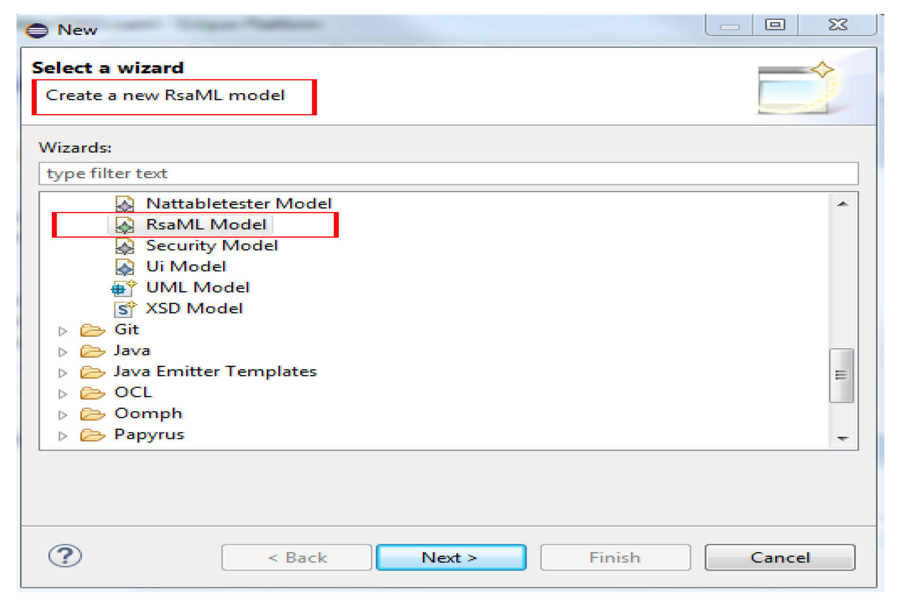
3.6. Implementation: Meta-Modeling in Eclipse

This subsection deals with the implementation of the abstract syntax of the RsaML language (its meta-model) and the integration of its semantic rules (as OCL constraints) in the meta-model, in order to verify their good working. The Framework EMF and the OCL project of Eclipse were, respectively, used for the implementation of the meta-model and the integration of OCL constraints in the meta-model.
Once the meta-model is built, it was checked to verify that all the syntactic rules of construction were satisfied (for example, to ensure that the type of each attribute was specified). The next step was, therefore, the integration of OCL constraints in the meta-model under Eclipse.
Before integrating the OCL constraints to the meta-model, each of them was first checked to ensure that it was syntactically correct, and provided the expected result. For this, the interactive console of the Eclipse OCL project was used. Figure 4 shows an example of verification with the result in the red rectangle. The result is False in this case, because two modules (m12,m12) have the same name.
In Figure 4, we have three blocks: The first contains the RsaML meta-model, which is presented in Figure 3; the second contains an instance of the meta-model, which represents an architecture in which two modules have the same name (m12 highlighted in yellow); the third is the interactive console that allows us to evaluate the constraints before their insertion in the meta-model. It presents a constraint and the result (red rectangle) that it produces when it is applied to the example model of block 2.
To add OCL constraints in the meta-model, its textual version is edited and constraints’ invariants are added, as shown in the red boxes in Figure 5.
After this presentation of the implementation of the abstract syntax and the semantics rules of RsaML, the next subsection is dedicated to the definition of a concrete syntax for RsaML.

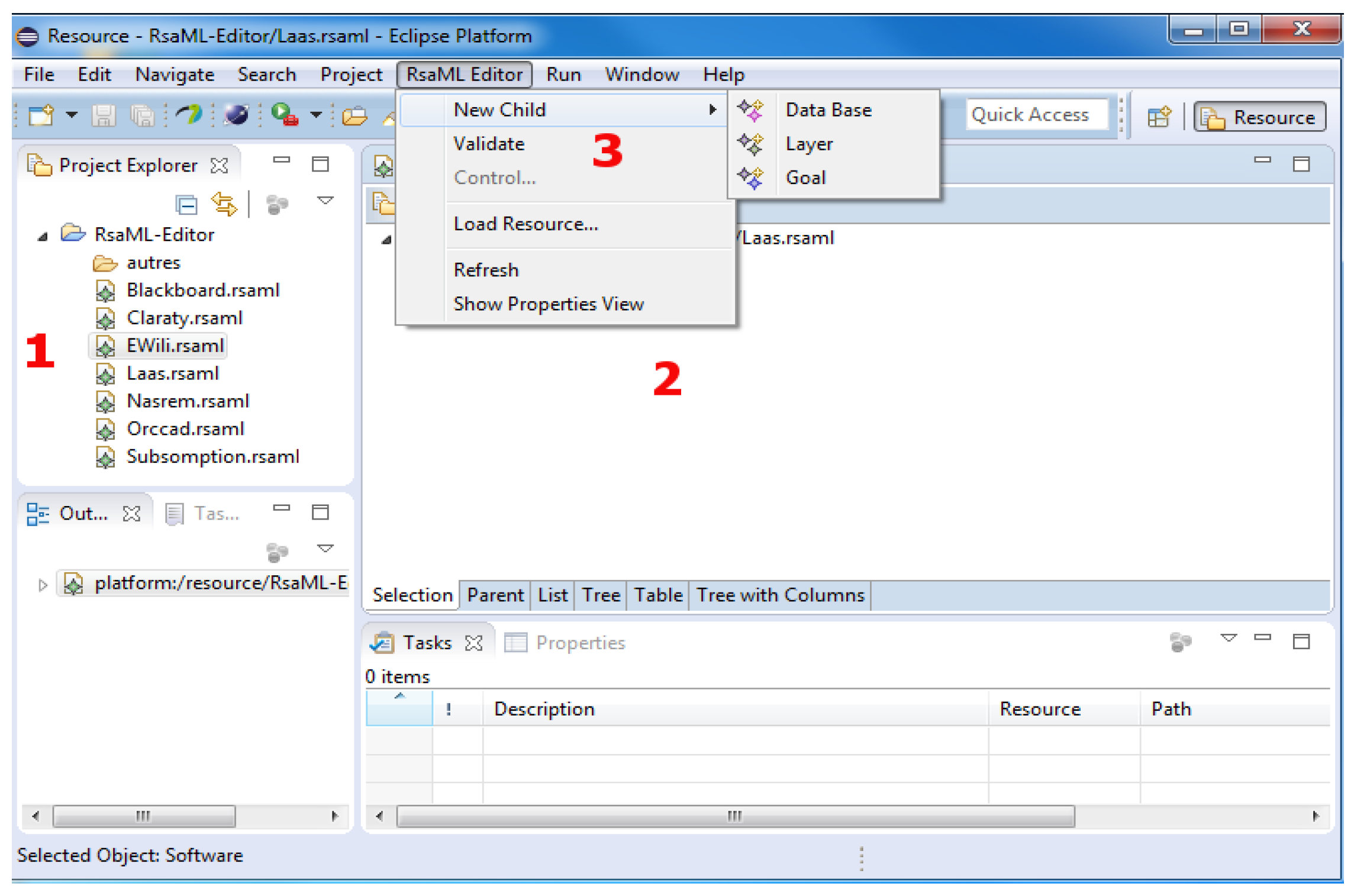
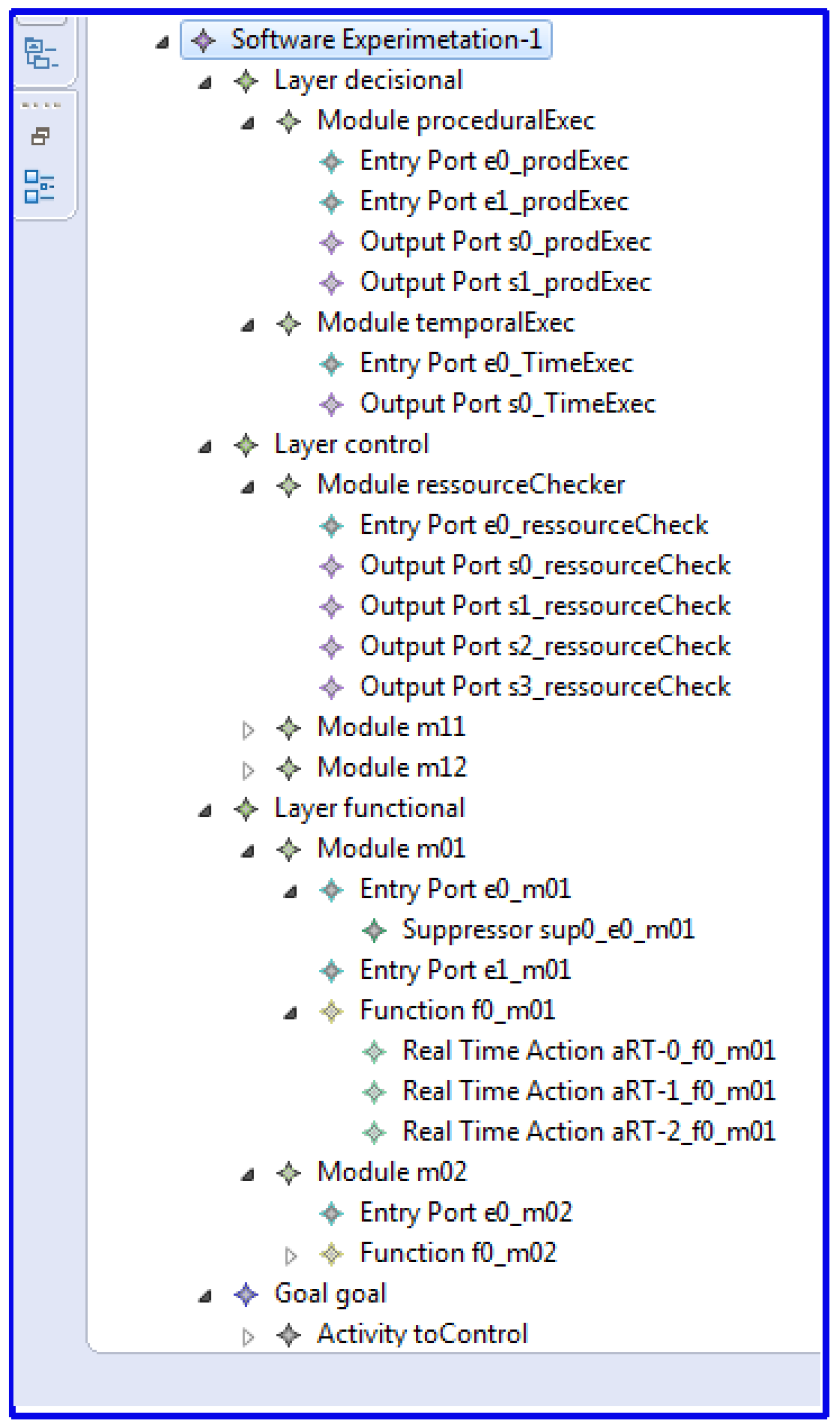
3.7. Definition of a Concrete Syntax: The Tree Editor of RsaML

The concrete syntax defines the interface and the notations that will be used by the users to represent the different concepts of the language, and thus to build their models (architectures). This syntax can take many forms. For this first version of RsaML, we propose a tree editor, which will be enriched later to evolve towards a graphic editor. Eclipse EMF offers the possibility of producing the tree editor from the abstract syntax (meta-model) of a language. This requires associating an editor generator with the meta-model. An EMF project was therefore created, and the meta-model was integrated in this project by importing the RsaML Ecore file. This led to the creation of a .genmodel file that is the template generator. Subsequently, the .genmodel project was used to generate code for a set of projects, including an .emf.editor project. The execution of the latter produced the RsaML tree editor presented in Figure 6.
The editor of Figure 6 has, among others (1, 2, and 3 in the figure):
  • An explorer of already created models. These models have a language-specific extension (.rsaml);
  • The space reserved for the construction of the models;
  • A menu allowing, among other things, to validate the model being built.
With this editor, RsaML models can now be built, just by choosing the type of model in the proposed list, as shown in the diagram of Figure 7.
After this presentation of the RsaML language, the next section deals with its validation through experimentions.

4. Validation: Experimentations of RsaML

Three experimentations were performed in order to validate the proposed DSML. They were chosen so as to show the use of the language for the modeling of a system having any type of architecture (i.e., belonging, or not, to the classical categories of robotics architectures), and to validate the semantic constraints defined in the language. The first experimentation uses the language to represent a category of architecture, the second focuses on the test of the semantics of the language, and the third represents a system whose architecture belongs to none of the classical robotics architectures.

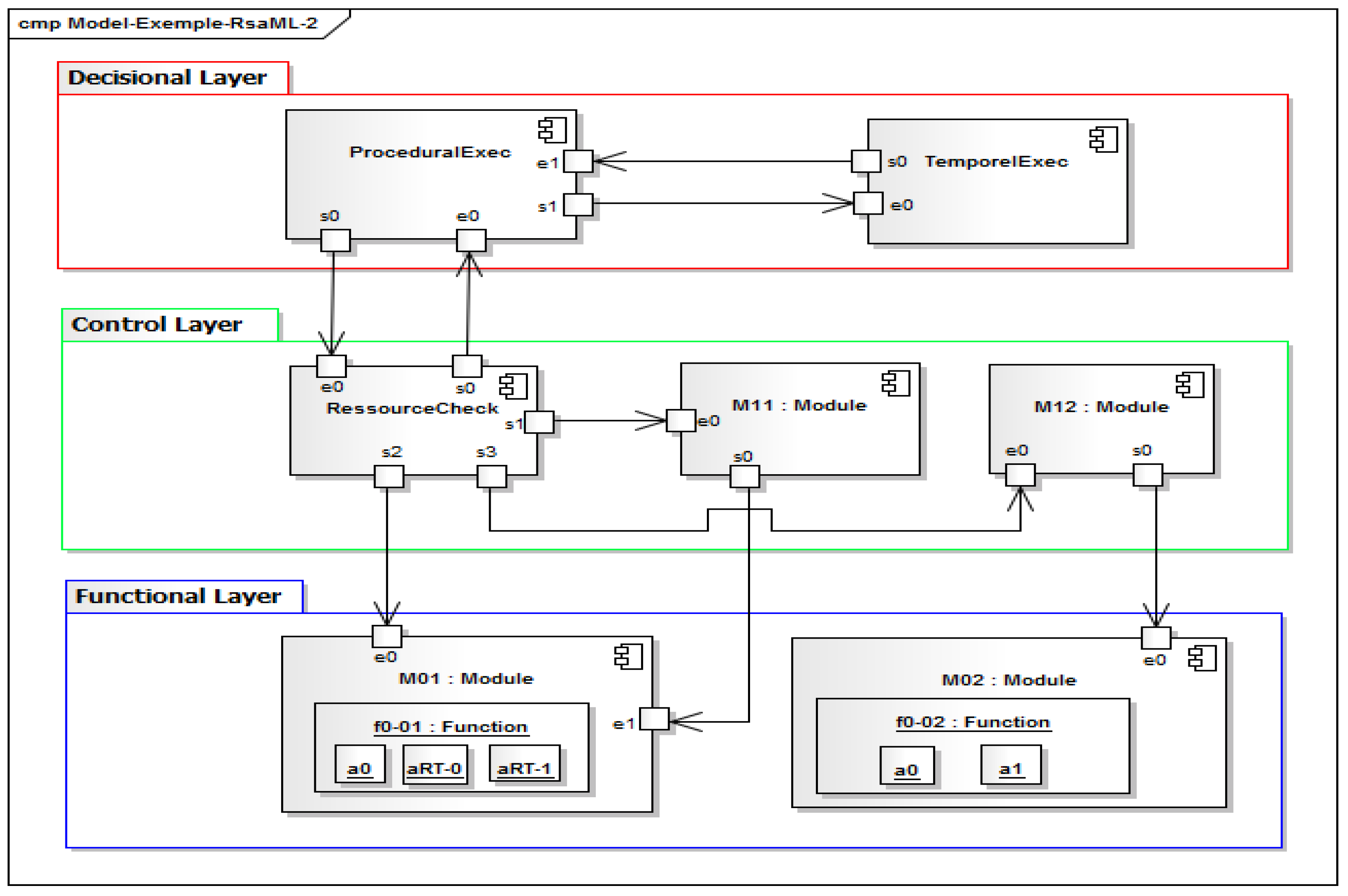
4.1. Experimentation 1: A Robotic System Having a Hybrid Architecture

The goal of this first experiment is to ensure that the language is operational and ready for use. For this, it is necessary to describe a system and to specify its architecture using the language. This section, therefore, begins with a description of the system to be modeled, and then presents the use of the RsaML language to build the model of its architecture.

4.1.1. Description of the System

The system considered is a robotic system whose software architecture belongs to the category of hybrid architectures. This category of architectures has been chosen because it is more representative. Indeed, as mentioned in Section 2.1.1, hybrid architectures combine the reactive capabilities of behavioral architectures and reasoning abilities (decision making) specific to hierarchical architectures. The proposed system has an architecture that is divided into three layers:
  • A decision layer containing two modules. A module called temporal executive, that manages the planning of the global mission of the robot, and another module that oversees the missions sent by human operators.
  • A control layer containing three modules. A module that checks the requests sent to the modules of the functional layer, another that verifies the use of the resources of the robot, and a last one that manages the aspects related to robustness and dependability.
  • A functional layer containing two modules that offer services via queries to start/stop/ parameterize them, and making it possible to manage physical and logical resources (sensors and others). These modules have functions containing the actions that are necessary for the control of these resources.
Figure 8 shows the block diagram of the architecture of this system.

4.1.2. Description of the Architecture with RsaML

The tree editor of RsaML presented in Section 3.7 has been used to build the architecture of the robotic system presented in the previous subsection. The diagram in Figure 9 shows the constructed model.
For a better understanding, Table 3 gives the correspondence between some elements of the robotic software architecture presented in Figure 8 and the corresponding RsaML concepts.
This first experimentation shows that the syntax of the RsaML language is operational. The second experimentation aims at testing RsaML semantics. It is presented in the next subsection.

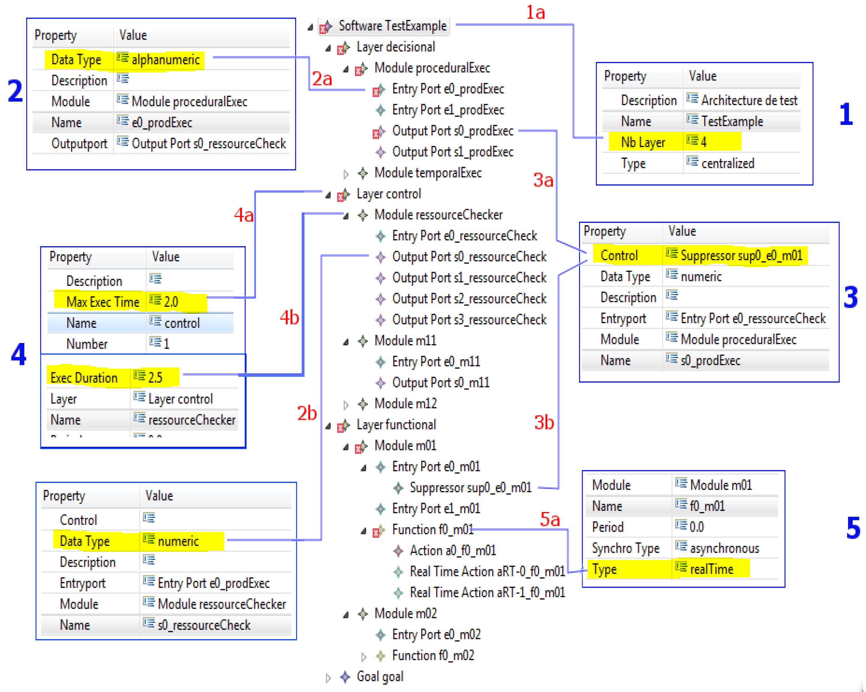
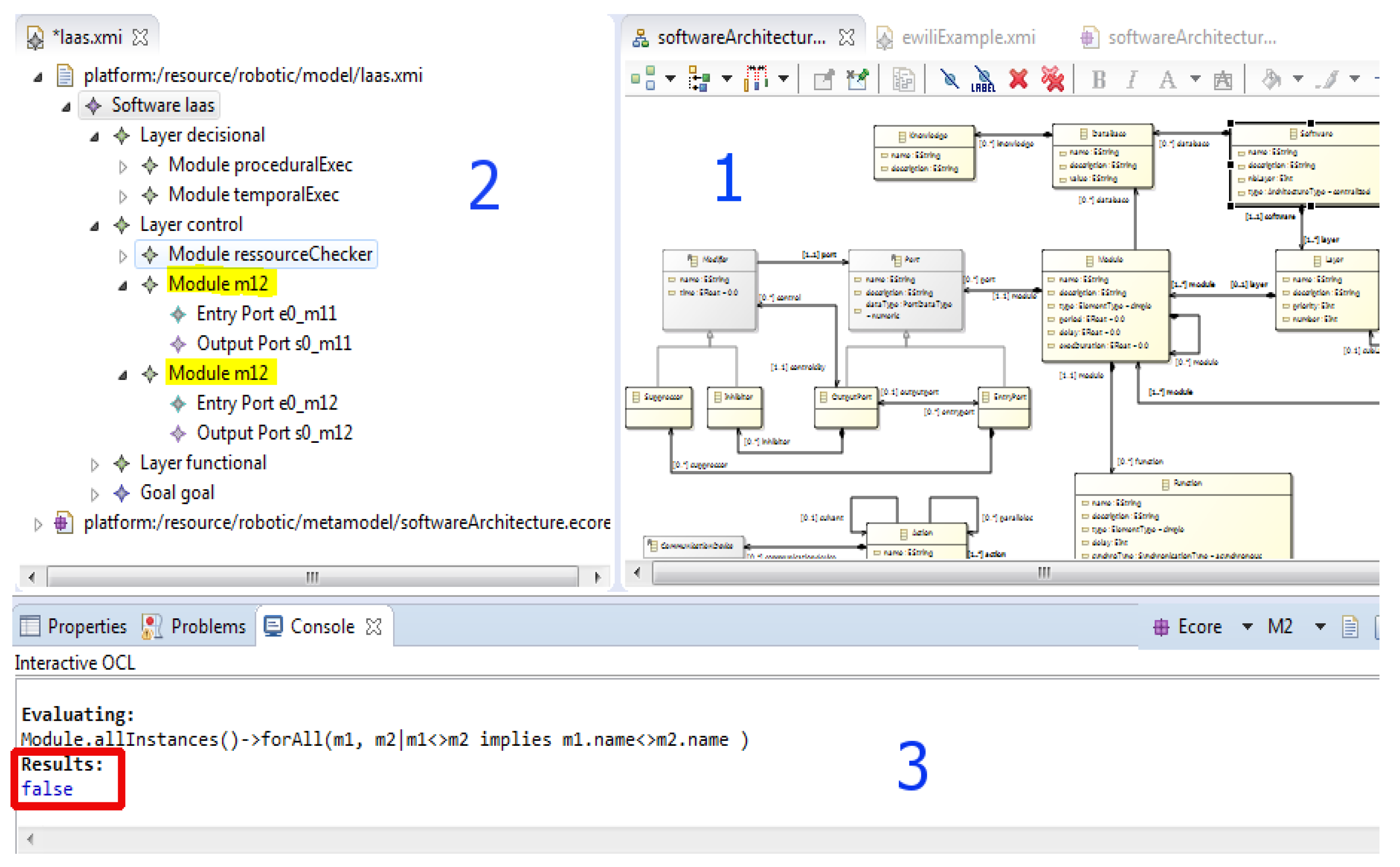
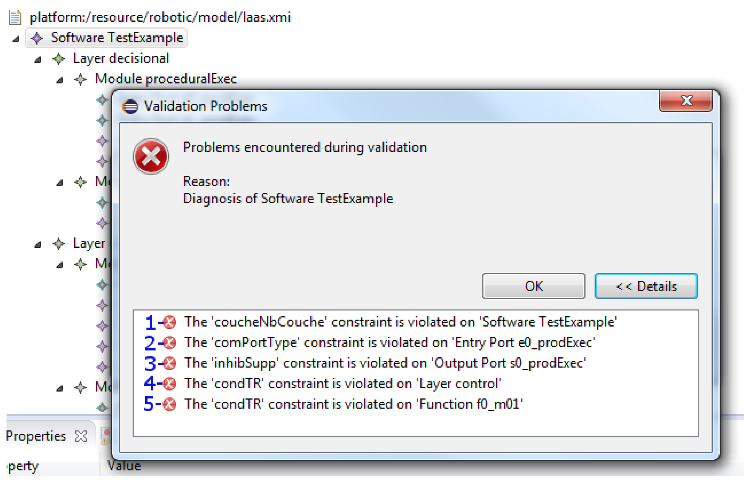
4.2. Experimentation 2: Test of Semantics and Verification of a Model

The objective is to check that the semantic rules in the meta-model (i.e., the abstract syntax of RsaML) are well integrated, making it possible to detect semantic errors correctly. In order to reach this goal, some semantic errors (with respect to the semantic rules defined) have been introduced in the case study described in Section 4.1.1, then the verification of the obtained model has been carried out and finally the errors generated have been compared with those expected.
The verification of the modified model (i.e., the model including semantic errors) generated five (5) errors as shown in Figure 10.
Figure 10 shows the errors generated as a result of the following anomalies:
  • The number of defined layers is different from the number of layers actually created;
  • A port communicates with another port whose data type is different from its own;
  • A module of layer n modifies the data of another module located at layer n-2;
  • The execution time of a module is greater than the maximum execution time defined for the layer that contains it;
  • A function is defined as real-time, but contains non-real-time actions.
Figure 11 shows details explaining these errors. It contains the numbers from 1 to 5 corresponding to the errors in Figure 10.
In the diagram of Figure 11:
  • The problem items carry a small red cross;
  • Extracts of couples (properties, values) of certain elements of the model are represented in rectangles connected to these elements by lines which we will call “links” in the following.
The diagram in Figure 11 shows the following:
  • Four (4) layers are declared for the architecture (link 1a), but only three layers (decisional, control, and functional) are actually created;
  • The type of data that the e0_prodExec input port can receive is “alphanumeric” (link 2a), but it is connected to the output port (its Outputport property) s0_ressourceCheck, which sends it data of type “numeric” (link 2b);
  • The proceduralExec module deletes the entry e0_m01 (link 3a) of module m01, which is at the functional layer (link 3b) at level n-2, whereas the decisional layer is at level n;
  • The execution duration of the resourceChecker module is 2.5 (link 4b), while the maximum time of execution of the layer where it is located is 2.0 (link 4a);
  • The function f0_m01 is real-time (link 5a), but it contains an action which is not real-time (action a0_f0_m01).
This experimentation shows that the integration of OCL constraints in the language works fine, that these constraints are well and truly verified when the language is used, and therefore that the static semantics of RsaML is potentially well defined.

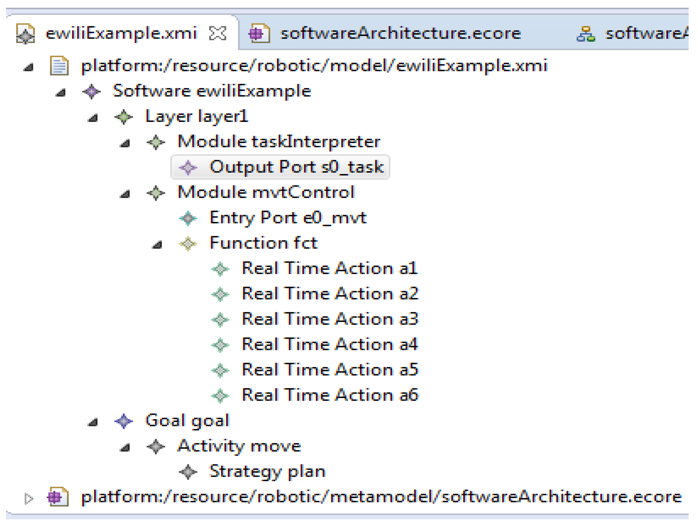
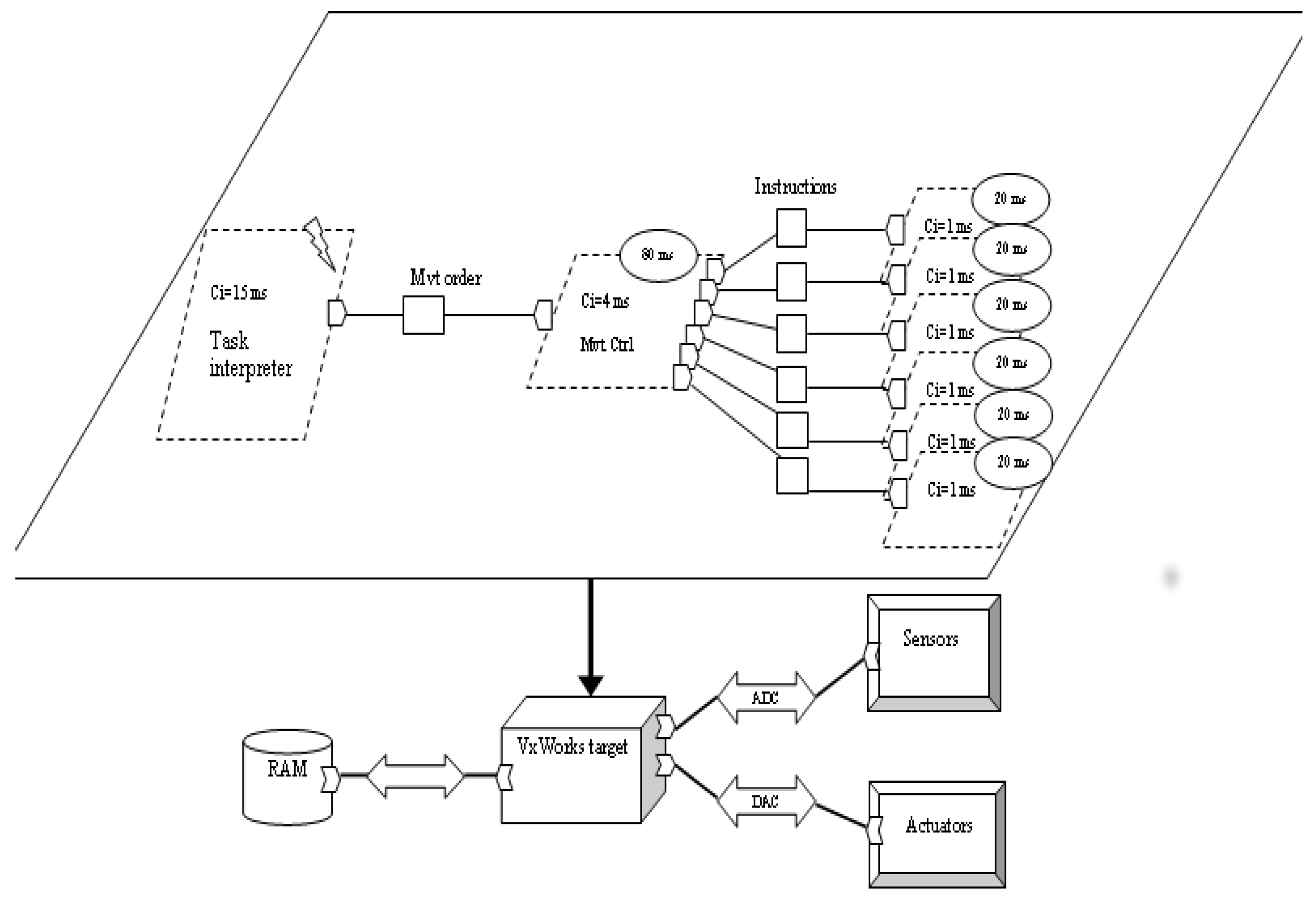
4.3. Experimentation 3: A Robotic System Whose Architecture Belongs to None of the Classical Categories of Architectures

The objective of this last experiment is to verify that the language RsaML can be used to model robotic systems whose architecture belongs to none of the classical categories of architectures. For this, we consider a robotic system taken from the literature and describe its software architecture with RsaML. The robotic system considered is described in [54]. It is a system with a real-time executive that is represented by a single processor. The latter is connected to the sensors and actuators via two acquisition cards. Figure 12 shows the structure of the robotic system.
To build the software architecture of this system using the RsaML language, we proceed as follows: The sensors and actuators (visible in the diagram of Figure 12) can be represented by the concepts of sensors and actuators defined in the language, an action (the parallelogram with the expression Ci = 1 ms, for example) by the concept of action, a task (the parallelogram named Mvt Ctrl, for example) by the concept of function, the execution system on which the real-time controller will be executed by the concept of processor, other software components (acquisition of sensor data, processing of these data, etc.) by the concept of module, the connections between the components by links between their respective ports, and the memory by a database and the whole system by the concept of Software. Thus, the architecture of this system is structured in a layer having two modules:
  • A task interpreter: it has a function to provide this service;
  • A motion controller: it has a function containing six actions named Instructions. These actions are periodic, and each has a period of 20 ms and an execution time of 1 ms.
We built this architecture using the RsaML tree editor. The obtained model is shown in Figure 13.
After these experimentations of RsaML, the next section discusses its advantages and limits.

5. Discussion

Part of the related works presented in Section 2.2 addressed the question of the application of MDE to the development of robotic software systems in general, and the other part addressed the specific problem of definition of DSML for robotics. Each of these works has contributed to filling the gaps regarding the application of software engineering methods and techniques to the robotics field. However, with respect to the questions raised in Section 1, these works present some shortcomings.
The work presented in [52] does not allow us to represent all categories of architectures. For example, it does not take into account specific aspects of behavioral architectures such as the mechanisms of inhibiting output and suppressing inputs. The works described in [55,58] do not address the specific issue of the representation of robotic software architectures. The proposition made by [56] is specific to the subsumption architecture. The study conducted by [53] concerns the specific case of the Aibo system, and the proposed meta-model is therefore restricted to this system. Likewise, the proposal made by [54] focuses on the development of the system for the control of a given prototype. Almost all of these works do not take into account the real-time aspects of robotic systems. Unlike the previous solutions, RsaML provides a solution taking into account all categories of robotic software architectures and all types of robotic systems. It makes it possible to take into account functional and non-functional properties of robotic systems that cannot be included graphically in the meta-model. RsaML also offers the ability to include and verify real-time properties for robotic systems that have time constraints.
As mentioned in Section 2.2, SmartSoft [63] brings a significant advance in the definition of DSML for robotics. We can recall, among other things, the interoperability provided by the possibility of generating code to CORBA and ACE (Adaptive Communication Environment). However, SmartSoft’s meta-model does not distinguish hardware components from software components of robotic systems. This has the consequence of reducing the level of abstraction and therefore the possibility of abstracting the material that must support the developed system. RsaML provides the ability to model software architectures independently of the underlying hardware by decoupling the hardware and software components of a system. The components of smartSoft are kinds of “black boxes” offered to manage the robot. Consequently, the possibilities to specify/modify the desired behaviors of these components are almost nil. Furthermore, the tasks do not explicitly describe the actions that carry them out. RsaML takes this level of granularity into account by making it possible to specify at the level of the architectural model, the components, and the tasks that constitute them as well as the actions of the latter. This way of doing things promotes the modularity of the architectures defined, increases the maintainability of the systems built, and facilitates the reusability of the components of the latter. The SmartMars meta-model on which SmartSoft is built does not integrate semantic rules for the management of non-functional properties. The authors made new works [69] dedicated to the modeling of non-functional constraints for robotic software systems. RobotML [64] has also paved the way for the application of software engineering in the field of robotics. However, unlike RsaML, RobotML does not allow checking the non-functional properties of built models. Moreover, although RobotML defines a property allowing to specify the type of a task in the constructed model (periodic, aperiodic, etc.), it does not offer elements for the specification of the real-time properties of the systems, which are essential elements to specify, for example, the policy and parameters for scheduling tasks.
Table 4 summarizes the comparison of RsaML with some of the proposed solutions, namely RobotML, GenoM3, SmartSoft, and BRIDE. The following criteria have been used for the comparison:
  • Ability to model any type of robotic software architecture;
  • Ability to describe the behaviour of the components (possibility for the user to specify new component and not only to use predefined components);
  • Ability to express non-functional properties;
  • Ability to express Real-time properties;
    with periodic tasks (PT);
    with aperiodic tasks (AT);
    with policy and scheduling parameters (PSP);
  • Defines a DSML (language);
  • Independent from the target platform.
As shown in Table 4, unlike the other approaches, RsaML satisfies all the criteria defined above.
The limit of the work presented in this paper is that it does not cover the whole software engineering process for the construction of robotic systems shown in Figure 1. Future works are planned to cover other steps of this process.

6. Conclusions and Future Work

Robotic systems which are special cases of embedded real-time systems suffer from the lack of development methods and processes that could systematize and facilitate their development, such as those found in the development of classical software. One of the key and topical issues is the application of software engineering techniques to robotics. One area of software engineering that opens new opportunities is model-driven engineering (MDE) that makes it possible to define Domain Specific Modeling Languages (DSML). In this article, we have addressed the issue of formalization of the description of robotic software architectures. A DSML called RsaML has been proposed for the design of the latter. It takes into account the different categories of robotic software architectures, with the possibility to specify real-time properties when necessary. In order to define this DSML, an analysis of the robotic domain was done and the different categories of software architectures were investigated. This analysis ended with the identification and description of concepts useful for the representation of these architectures. Useful attributes to take into account real-time properties were identified, defined, and integrated into the relevant concepts. A meta-model was proposed to describe robotic software architectures. This meta-model defines the abstract syntax of RsaML. The static semantics of the language were defined and integrated in the meta-model using OCL constraints. These OCL constraints make it possible to verify semantic rules specific to the field of robotics as well as real-time properties. The Eclipse EMF Framework was used to implement the RsaML language and experiments were performed to validate the proposed solution. The comparison with related works shows that RsaML provides several advantages. Unlike solutions proposed in most of the related works, RsaML takes into account the different categories of architectures and the functional and non-functional properties of robotic software systems. By decoupling the representation of software components from that of hardware components, it is possible to define architectures independently of the underlying hardware. This offers the possibility of detailing the actions carrying out the behavior of a software component. This level of granularity increases the maintainability and reusability of the architectures built, and makes communication between experts of the robotic domain easier. RsaML also makes it possible to specify real-time properties of robotic systems, including policy and parameters for tasks’ scheduling.
Future work aims to develop a graphic editor to facilitate the representation of robotic software architectures as well as a model transformation engine, so as to offer a complete chain from modeling to code generation.

Author Contributions

Main idea and conceptualization, V.M.M.; methodology, V.M.M. and L.N.; analysis and design, V.M.M.; software, V.M.M.; validation, V.M.M., L.N. and G.E.K.; resources, V.M.M. and L.N.; writing—original draft preparation, V.M.M.; writing—review and editing, V.M.M., L.N. and G.E.K.; and supervision, L.N. All authors have read and agreed to the published version of the manuscript.

Funding

The APC was funded by the Lab-STICC Laboratory and the Institute of Brest for Numeric and Mathematics (IBNM).

Institutional Review Board Statement

Not applicable.

Informed Consent Statement

Not applicable.

Data Availability Statement

The study did not report any data.

Conflicts of Interest

The authors declare no conflict of interest.

References

  1. Brugali, D.; Reggiani, M. Software stability in the robotics domain: Issues and challenges. In Proceedings of the IRI-2005 IEEE International Conference on Information Reuse and Integration, Las Vegas, NV, USA, 15–17 August 2005; pp. 585–591. [Google Scholar]
  2. Passama, R.; Andreu, D.; Crestani, D.; Godary-Dejean, K. Architectures de contrôle pour la robotique—Approches et tendances. Tech. L’Ingenieur 2014, 1, S7791. [Google Scholar] [CrossRef]
  3. Nana, L.; Monin, F.; Gire, S. Formal Proof of Properties of a Syntax-Oriented Editor of Robotic Missions Plans. Adv. Sci. Technol. Eng. Syst. J. 2021, 6, 1049–1057. [Google Scholar] [CrossRef]
  4. Molina, M.; Carrera, A.; Camporredondo, A.; Bavle, H.; Rodriguez-Ramos, A.; Campoy, P. Building the executive system of autonomous aerial robots using the Aerostack open-source framework. Int. J. Adv. Robot. Syst. 2020, 17, 1–20. [Google Scholar] [CrossRef]
  5. Bettini, L.; Bourr, K.; Pugliese, R.; Tiezzi, F. Writing Robotics Applications with X-Klaim. In Leveraging Applications of Formal Methods, Verification and Validation: Engineering Principles, ISoLA 2020; Margaria, T., Steffen, B., Eds.; Lecture Notes in Computer Science; Springer: Cham, Switzerland, 2020. [Google Scholar]
  6. Zhang, Y.-N.; An, M.-Q. A Compact and Reliable Software Architecture for Robotics Control. In Proceedings of the 2021 IEEE International Conference on Information Communication and Software Engineering (ICICSE), Chengdu, China, 19–21 March 2021; pp. 41–46. [Google Scholar] [CrossRef]
  7. Kolak, S.; Afzal, A.; Le Goues, C.; Hilton, M.; Timperley, C.S. It Takes a Village to Build a Robot: An Empirical Study of The ROS Ecosystem. In Proceedings of the 2020 IEEE International Conference on Software Maintenance and Evolution (ICSME), Adelaide, SA, Australia, 27 September–3 October 2020; pp. 430–440. [Google Scholar] [CrossRef]
  8. Rendiniello, A. A Flexible Software Architecture for Robotic Industrial Applications. In Proceedings of the 25th IEEE International Conference on Emerging Technologies and Factory Automation (ETFA), Vienna, Austria, 8–11 September 2020; pp. 1273–1276. [Google Scholar] [CrossRef]
  9. Efremov, M.A.; Kholod, I.I. Architecture of Swarm Robotics System Software Infrastructure. In Proceedings of the 9th Mediterranean Conference on Embedded Computing (MECO), Budva, Montenegro, 8–11 June 2020; pp. 1–4. [Google Scholar] [CrossRef]
  10. Malavolta, I.; Lewis, G.; Schmerl, B.; Lago, P.; Garlan, D. How do you Architect your Robots? State of the Practice and Guidelines for ROS-based Systems. In Proceedings of the IEEE/ACM 42nd International Conference on Software Engineering: Software Engineering in Practice (ICSE-SEIP), Seoul, Korea, 23–29 May 2020; pp. 31–40. [Google Scholar]
  11. Demeter, R. Cognitive robotics software development aspects based on experiments of future software engineers. In Proceedings of the 11th IEEE International Conference on Cognitive Infocommunications (CogInfoCom), Mariehamn, Finland, 23–25 September 2020; pp. 459–464. [Google Scholar] [CrossRef]
  12. Tröbinger, M. Introducing GARMI—A Service Robotics Platform to Support the Elderly at Home: Design Philosophy, System Overview and First Results. IEEE Robot. Autom. Lett. 2021, 6, 5857–5864. [Google Scholar] [CrossRef]
  13. Trezzy, M.; Ober, I.; Oliveira, R. Leveraging domain specific modeling to increase accessibility of robot programming. In Proceedings of the IEEE International Workshop of Electronics, Control, Measurement, Signals and Their Application to Mechatronics (ECMSM), Liberec, Czech Republic, 21–22 June 2021; pp. 1–9. [Google Scholar] [CrossRef]
  14. Hong, H.; Kang, W.; Ha, S. Software Development Framework for Cooperating Robots with High-level Mission Specification. In Proceedings of the IEEE/RSJ International Conference on Intelligent Robots and Systems (IROS), Las Vegas, NV, USA, 24 January 2021; pp. 11615–11622. [Google Scholar] [CrossRef]
  15. Salas, R.P. Reusable Learning Objects: An Agile Approach. In Proceedings of the IEEE Frontiers in Education Conference (FIE), Uppsala, Sweden, 21–24 October 2020; pp. 1–6. [Google Scholar] [CrossRef]
  16. Muratore, L.; Laurenzi, A.; Mingo Hoffman, E.; Tsagarakis, N.G. The XBot Real-Time Software Framework for Robotics: From the Developer to the User Perspective. IEEE Robot. Autom. Mag. 2020, 27, 133–143. [Google Scholar] [CrossRef]
  17. Triantafyllou, P. A Methodology for Approaching the Integration of Complex Robotics Systems: Illustration Through a Bimanual Manipulation Case Study. IEEE Robot. Autom. Mag. 2021, 28, 88–100. [Google Scholar] [CrossRef]
  18. De Araujo Silva, E.; Valentin, E.; Carvalho, J.R.H.; Da Silva Barreto, R. A survey of Model Driven Engineering in robotics. J. Comput. Lang. 2021, 62, 101021. [Google Scholar] [CrossRef]
  19. El Jalaoui, A. Gestion Contextuelle de Tâches Pour le Contrôle D’un véhicule Sous-Marin Autonome. Ph.D. Thesis, Faculté des Sciences de Montpellier, Montpellier, France, 2007. [Google Scholar]
  20. Nana, L. Architectures logicielles pour la robotique. In Proceedings of the Journees Nationales de la Recherche en Robotique (JNRR’05), Guidel, France, 5–7 October 2005; pp. 239–248. [Google Scholar]
  21. Albus, J.; McCain, H.; Lumia, R. In Proceedings of the 20th International Symposium on Industrial Robots, Tokyo, Japan, 4–6 October 1989.
  22. Kotseruba, I.; Tsotsos, J.K. 40 years of cognitive architectures: Core cognitive abilities and practical applications. Artif. Intell. Rev. 2020, 53, 17–94. [Google Scholar] [CrossRef] [Green Version]
  23. AlbusGat, E.; Bonnasso, R.; Murphy, R. On three-layer architectures. Artif. Intell. Mob. Robot. 1998, 198, 210. [Google Scholar]
  24. Tate, A.; Drabble, B.; Kirby, R. O-Plan2: An Open Architecture for Command, Planning and Control; Artificial Intelligence Applications Institute, University of Edinburgh: Edinburgh, Scotland, 1992. [Google Scholar]
  25. Lumia, R.; Fiala, J.; Wavering, A. The NASREM robot control system and testbed. IEEE J. Robot. Autom. 1990, 5, 20–26. [Google Scholar]
  26. Hassoun, M.; Laugier, C. Reactive motion planning for an intelligent vehicle. In Proceedings of the Intelligent Vehicles92 Symposium, Detroit, MI, USA, 29 June–1 July 1992; pp. 259–264. [Google Scholar]
  27. Tigli, J.Y. Vers une Architecture de Controle Pour Robot Mobile Orientée Comportement, SMACH. Ph.D. Thesis, University of Nice Sophia Antipolis, Nice, France, 1996. [Google Scholar]
  28. Darvish, K.; Simetti, E.; Mastrogiovanni, F.; Casalino, G. A Hierarchical Architecture for Human–Robot Cooperation Processes. IEEE Trans. Robot. 2021, 37, 567–586. [Google Scholar] [CrossRef]
  29. Brooks, R. A robust layered control system for a mobile robot. IEEE J. Robot. Autom. 1986, 2, 14–23. [Google Scholar] [CrossRef] [Green Version]
  30. Rosenblatt, J. DAMN: A distributed architecture for mobile navigation. J. Exp. Theor. Artif. Intell. 1997, 9, 339–360. [Google Scholar] [CrossRef]
  31. Martín, F.; Rodríguez Lera, F.J.; Ginés, J.; Matellán, V. Evolution of a Cognitive Architecture for Social Robots: Integrating Behaviors and Symbolic Knowledge. Appl. Sci. 2020, 10, 6067. [Google Scholar] [CrossRef]
  32. Schneider, S.A.; Chen, V.W.; Pardo-Castellote, G.; Wang, H.H. ControlShell: A software architecture for complex electro-mechanical systems. Int. J. Robot. Res. Spec. Issue Integr. Archit. Robot Control Program. 1998, 17, 360–380. [Google Scholar]
  33. Alami, R.; Chatila, R.; Fleury, S.; Ghallab, M.; Ingrand, F. An Architecture for Autonomy. Int. J. Robot. Res. 1998, 17, 315–337. [Google Scholar] [CrossRef]
  34. Simon, D.; Kapellos, K.; Espiau, B. Control laws, tasks, procedures with ORCCAD; application to the control of an underwater arm. Int. J. Syst. Sci. 1998, 29, 1081–1098. [Google Scholar] [CrossRef]
  35. Simon, D.; Espiau, B.; Castillo, E.; Kapellos, K. Computer-aided design of a generic robot controller handling reactivity and real-time control issues. IEEE Trans. Control Syst. Technol. 1993, 1, 213–229. [Google Scholar] [CrossRef]
  36. Volpe, R.; Nesnas, I.; Estlin, T.; Mutz, D.; Petras, R.; Das, H. Claraty: Coupled Layer Architecture for Robotic Autonomy; Technical Report; Jet Propulsion Laboratory: Pasadena, CA, USA, 2000.
  37. Volpe, R.; Nesnas, I.; Estlin, T.; Mutz, D.; Petras, R.; Das, H. The claraty architecture for robotic autonomy. In Proceedings of the 2001 IEEE Aerospace Conference Proceedings (Cat. No.01TH8542), Big Sky, MT, USA, 10–17 March 2001. [Google Scholar]
  38. Oliveira, P.; Pascoal, A.; Silva, V.; Silvestre, C. Design, development, and testing at sea of the mission control system for the MARIUS autonomous underwater vehicle. In Proceedings of the OCEANS 96 MTS/IEEE Conference Proceedings. The Coastal Ocean—Prospects for the 21st Century, Fort Lauderdale, FL, USA, 23–26 September 1996; pp. 401–406. [Google Scholar]
  39. Arkin, R.C.; Balch, T. AuRA: Principles and practice in review. J. Exp. Theor. Artif. Intell. 1997, 9, 175–189. [Google Scholar] [CrossRef]
  40. Schmidt, D. Model-driven engineering. Comput.-IEEE Comput. Soc. 2006, 39, 25. [Google Scholar] [CrossRef]
  41. Combemale, B. Ingénierie Dirigée par les Modèles (IDM)—État de L’art. Research Report. 2008. Available online: https://hal.archives-ouvertes.fr/hal-00371565/ (accessed on 7 December 2020).
  42. Niemann, S. Executable Systems Design with UML 2.0. In OMG Whitepapers on UML; Object Management Group: Needham, MA, USA, 2004. [Google Scholar]
  43. Kleppe, A. Software Language Engineering: Creating Domain-Specific Languages Using Metamodels; Pearson Education: London, UK, 2008. [Google Scholar]
  44. Brambilla, M.; Cabot, J.; Wimmer, M. Model-driven software engineering in practice. Synth. Lect. Softw. Eng. 2012, 3, 1–182. [Google Scholar] [CrossRef] [Green Version]
  45. Bazex, P.; Bodeveix, J.; Le Camus, C.; Millan, T.; Percebois, C. Vérification de Modèles UML Fondée sur OCL. Research Report. 2003. Available online: https://d1wqtxts1xzle7.cloudfront.net/39471554/Vrification_de_modles_UML_fonde_sur_OCL20151027-2311-1rjb2p0-with-cover-page-v2.pdf?Expires=1647324644&Signature=KZaAYLjQfgwLsosyV1E2aziSn0TKj6JXpq~sVPlN1-AtKxhzo~35qFVPya4vw~QvVL2w2pg6b–XWdfO5LQYDFL2hhQJ2IKennxg0IJSiF1iT2mosELp~U~DzYQBFurWugdM73qCG78gJfZTpye6ywp5MaR2~1MY3zYAItSywXdwITpvJExrrxHLK8TycUpW-jm1IkCbvpLx2JYtER0f1I97Czy5MaUnhPs5CxYXaXLnaVFzHXfQi4T~jMO2~uuw4AYaMWt1EytPMoNial9I4ZNKQwNcl2zevrIensp5kaYbuYLa9fXW3Ve8q28nVR2qlcq3mkJj2xffpOvMybn35Q__&Key-Pair-Id=APKAJLOHF5GGSLRBV4ZA (accessed on 7 December 2020).
  46. Object Management Group. Meta Object Facility (MOF) Core Specification; Object Management Group: Needham, MA, USA, 2015. [Google Scholar]
  47. Object Management Group. Object Constraint Language (OCL); Object Management Group: Needham, MA, USA, 2014. [Google Scholar]
  48. Object Management Group. MOF Model to Text Transformation Language; Object Management Group: Needham, MA, USA, 2008. [Google Scholar]
  49. Steinberg, D.; Budinsky, F.; Merks, E.; Paternostro, M. EMF: Eclipse Modeling Framework; Pearson Education: London, UK, 2008. [Google Scholar]
  50. Object Management Group. Unified Modeling Language (OMG UML). Superstructure, Version 2.3; Object Management Group: Needham, MA, USA, 2010. [Google Scholar]
  51. Kelly, S.; Tolvanen, J. Domain-Specific Modeling: Enabling Full Code Generation; John Wiley & Sons: Hoboken, NJ, USA, 2008. [Google Scholar]
  52. Passama, R. A Modeling Language for Communicating Architectural Solutions in the Domain of Robot Control. In Proceedings of the 2nd National Workshop on “Control Architectures of Robots: From Models to Execution on Distributed Control Architectures”, CAR 2007, Paris, France, 31 May–1 June 2007; pp. 109–121. [Google Scholar]
  53. Blanc, X.; Delatour, J.; Ziadi, T. Benefits of the MDE approach for the development of embedded and robotic systems. In Proceedings of the 2nd National Workshop on “Control Architectures of Robots: From Models to Execution on Distributed Control Architectures”, CAR 2007, Paris, France, 31 May–1 June 2007. [Google Scholar]
  54. Thomas, D.; Baron, C.; Tondu, B. Ingénierie Dirigée par les Modèles Appliquée à la Conception d’un Contrôleur de Robot de Service. Idm06 2007. [Google Scholar]
  55. Steck, A.; Schlegel, C. Towards quality of service and resource aware robotic systems through model-driven software development. arXiv 2010, arXiv:1009.4877. [Google Scholar]
  56. Trojanek, P. Model-driven engineering approach to design and implementation of robot control system. arXiv 2013, arXiv:1302.5085. [Google Scholar]
  57. Brugali, D.; Salvaneschi, P. Stable aspects in robot software development. Int. J. Adv. Robot. Syst. 2006, 3, 17–22. [Google Scholar] [CrossRef] [Green Version]
  58. Schlegel, C.; Haßler, T.; Lotz, A.; Steck, A. Robotic software systems: From code-driven to model-driven designs. In Proceedings of the 2009 International Conference on Advanced Robotics, Munich, Germany, 22–26 June 2009; pp. 1–8. [Google Scholar]
  59. Bersani, M.; Soldo, M.; Menghi, C.; Pelliccione, P.; Rossi, M. Pursue-from specification of robotic environments to synthesis of controllers. Form. Asp. Comput. 2020, 32, 187–227. [Google Scholar] [CrossRef] [Green Version]
  60. Menghi, C.; Tsigkanos, C.; Pelliccione, P.; Ghezzi, C.; Berger, T. Specification patterns for robotic missions. IEEE Trans. Softw. Eng. 2021, 47, 2208–2224. [Google Scholar] [CrossRef] [Green Version]
  61. Brugali, D.; Hochgeschwender, N. Software product line engineering for robotic perception systems. Int. J. Semant. Comput. 2018, 12, 89–107. [Google Scholar] [CrossRef]
  62. Kchir, S. Faciliter le Développement des Applications de Robotique. Ph.D. Thesis, University of Paris, Paris, France, 2014. [Google Scholar]
  63. Schlegel, C.; Steck, A.; Lotz, A. Model-driven software development in robotics: Communication patterns as key for a robotics component model. In Introduction to Modern Robotics; iConcept Press: Hong Kong, China, 2011; pp. 119–150. [Google Scholar]
  64. Dhouib, S.; Kchir, S.; Stinckwich, S.; Ziadi, T.; Ziane, M. Robotml, a domain-specific language to design, simulate and deploy robotic applications. In Simulation, Modeling, and Programming for Autonomous Robots; Springer: Berlin/Heidelberg, Germany, 2012; pp. 149–160. [Google Scholar]
  65. Dennis, S.; Alex, L.; Matthias, L.; Christian, S. The Smartmdsd Toolchain: An Integrated Mdsd Workflow and Integrated Development Environment (ide) for Robotics Software. J. Softw. Eng. Robot. 2016, 7, 3–19. [Google Scholar]
  66. OMG®. CORBA: Common Object Request Broker Architecture; Object Management Group: Needham, MA, USA, 2018. [Google Scholar]
  67. Schmidt, D. The ADAPTIVE Communication Environment An Object-Oriented Network Programming Toolkit for Developing Communication Software. In Proceedings of the 12th Sun User Group Conferences, San Francisco, CA, USA, 14–17 June 1993. [Google Scholar]
  68. Proteus. Available online: http://www.anr-proteus.fr/ (accessed on 7 December 2020).
  69. Lotz, A.; Hamann, A.; Lutkebohle, I.; Stampfer, D.; Lutz, M.; Schlegel, C. Modeling Non-Functional Application Domain Constraints for Component-Based Robotics Software Systems. arXiv 2016, arXiv:1601.02379. [Google Scholar]
Figure 1. General software system development process.
Applsci 12 02982 g001
Figure 2. Conceptualization of components used for the description of robotic software architectures.
Applsci 12 02982 g002
Figure 3. Proposed meta-model for the definition of robotics software architectures.
Applsci 12 02982 g003
Figure 4. Syntax checking of OCL constraints.
Applsci 12 02982 g004
Figure 5. Integration of OCL constraints in Ecore meta-model.
Applsci 12 02982 g005
Figure 6. The RsaML editor for description of robotic software architectures.
Applsci 12 02982 g006
Figure 7. Dialog box for the creation of a new RsaML model.
Applsci 12 02982 g007
Figure 8. The architecture of the system to be modeled.
Applsci 12 02982 g008
Figure 9. The RsaML model corresponding to the architecture presented in Figure 8.
Applsci 12 02982 g009
Figure 10. Semantic errors detected thanks to the semantic rules of RsaML.
Applsci 12 02982 g010
Figure 11. Details showing and explaining the erroneous points of the constructed model.
Applsci 12 02982 g011
Figure 12. An example of robotic system architecture [54].
Applsci 12 02982 g012
Figure 13. The RsaML model corresponding to the robotic architecture presented in Figure 12.
Applsci 12 02982 g013
Table 1. An extract of the concepts used in the language definition.
ConceptsDescriptions
Actionbasic task of the robot
Actuatorallows the robot to act on the environment
Activitytask or sequence of tasks of the robot
Databasedatabase, knowledge base, etc.
Functionset of functions implementing a module
Goalgoal to be achieved by the robot; it can have sub-goals
Inhibitorallows to inhibit some outputs
Knowledgedata handled and how they are used
Layerlevel in the hierarchy of the architecture
Missionestablished set of goals, tasks, and paths
Moduleany robotic software component
Orderorder sent to the robot to perform a task
Plansequence of actions to perform a mission
Portsallows communication between modules; they can be input or output ports
Sensorallows the robot to detect its environment
Supervisorcontrols plans execution
Suppressorallows to remove or modify entries
Table 2. The real-time properties used in the RsaML meta-model.
AttributesDescriptionsConcepts
MaxExecTimeMaximum execution timelayer
typetype of the element (simple or real-time)activity, module, action, function
periodperiod of execution- - - - -
delayresponse time- - - - -
execDurationexecution duration- - - - -
startDatestart timeaction
timeUnittime unit- - - - -
execTypesporadic, periodic or not- - - - -
synchroTypesynchronous or notfunction
schedPolicyscheduling Policy: FIFO, SJF, RR, RM, DM, EDF, LLF, etc.function
Table 3. Correspondence between some elements of Figure 8 and the concepts of RsaML.
Element of the SystemConcepts of RsaML
Decision LayerLayer
Procedural ExecModule
f0-01Function
a0Action
aRTRTAction
e0EntryPort
s0OutPutPort
Table 4. Comparison of RsaML with other proposals.
ProposalsRobotic Software ArchitectureBehaviour of the ComponentsNon-Functional PropertiesDefines a DSMLIndependent from PlatformReal-Time Properties
PTATPSP
RobotMLxx xxxx
GenoM3xx xxx
SmartSoftx xxx
BRIDEx x
RsaMLxxxxxxxx
Publisher’s Note: MDPI stays neutral with regard to jurisdictional claims in published maps and institutional affiliations.

