Abstract
In order to solve the problems of multiple process parameters, difficult control and high process requirements in laser first/second scribing of aerospace chemical milling thin-wall parts, a laser scribing depth model based on thermal energy balance was established, and the relationship between laser power and speed was established with scribing depth as a target. Using AC850 laser scribing maskant as coating material, the effects of laser power, scribing speed, laser frequency, forward angle and side slope angle on the scribing depth were studied by single factor experiment. Experimental results show that the theoretical model is in good agreement with experimental data. The laser scribing depth is positively proportional to the laser power and inversely proportional to the laser speed and has little relationship with the laser frequency. The predicted accuracy of the mathematical equations regarding the laser power density and scribing depth, calculated by the laser power, speed and scribing depths experimental data, are 88.53% and 90.79%. The laser scribing depth at a forward angle of 6° and a side slope angle of 7° is deeper compared with the vertical incident scribing depth, and the angle is also the recommended angle of laser scribing. Based on the simplified regression model, the laser scribing depth model can be directly used in the laser NC system to realize the adaptive adjustment and accurate control of laser energy according to the actual laser speed.
1. Introduction
In order to meet the lightweight requirements of aerospace, a large number of thin-walled parts with complex form features are widely designed and applied, which poses great challenges to existing manufacturing technologies [1,2]. At present, the thin-walled parts of aerospace are produced via chemical milling after traditional metal cutting, in which the excess metal on the surface of the parts is removed by chemical milling to form features such as reinforcing ribs and structural bosses [3,4,5]. Chemical milling is a non-traditional machining process where a chemical solution is used to selectively remove material from a workpiece using a strong chemical reagent known as etchant [6,7]. Before chemical milling, the surface of parts should be coated with maskant. Then, some maskant is trimmed away, and the uncovered area is subject to etching. The maskant could be cut by mechanical cutting or by laser ablation, which is called the scribing process in chemical milling [8,9]. The scribing process in chemical milling has become one of the key processes for manufacturing and chemical milling aviation equipment parts [10].
Laser scribing in chemical milling is developed from traditional manual scribing, which is an important process in the chemical milling for aerospace parts. In essence, it is a technological process of laser ablation for a chemical milling maskant on the surface of aluminum or titanium, which is to scribe form patterns on the surface of parts with the metal substrate material not damaged. Laser scribing combines a laser with multi-axis CNC machining to ensure scribing is carried out efficiently and precisely; it is programmed based on the geometric pattern information and process parameters of chemical milling. Laser scribing can be used for the first and second scribing on complex surfaces and provides a new solution to solve the bottleneck problem of scribing in the chemical milling process of aerospace complex thin-walled structural parts [11].
When laser scribing is combined with five-axis numerical control, the processing of complex patterns of three-dimensional parts can be realized. In general laser processing, laser scribing parameters such as laser power, pulse repetition frequency, feed speed, incident angle and other parameters are usually set before the start of processing and do not change during the process. However, due to the restriction of laser scribing trajectory and dynamic performance of machine tools, when the feed speed is set at a higher level, the actual feed speed is often difficult to reach the programmed value. The actual feed speed is subject to a variety of factors, including the structure of machine tools, loads, and curvature changes of machining characteristics, so the specific control will become more difficult. Therefore, it is very important to study the accurate control method of removal amount in NC laser scribing and realize the equal removal of materials to ensure the accurate manufacturing of protective adhesive surface patterns in chemical milling.
The scribing quality strictly depends on the process parameters, and it is important to choose optimized process parameters according to the productivity and the required cut properties. As early as the 1970s, laser scribing was proposed and applied to semiconductor manufacturing [12]. In 1987, Gnanamuthu DS from Boeing North American Inc Dallas, TX, USA [13] disclosed a laser method for scribing chemical milling, in which the Nd:YAG (wavelength = 1.06 pum), the Nd:Glass (wavelength = 1.06 m) and CO2 (wavelength = 10.6 um) laser beams controlled by NC or CNC were used to scribe the maskant. In 1992, Slysh P [14] proposed a laser-assisted masking process, which is a method of accurately applying maskant to a workpiece using one or more scanned laser beams and a maskant delivery device. In 2003, Griffin [15] studied laser scribing for chemical milling maskant and proposed that the light energy emitted from lasers in the 200–500 W range will reflect from the aluminum substrate with no damage to the substrate. In 2010, Leone C [8] studied the application of laser ablation in chemical milling in aeronautics and astronautics and analyzed laser power/speed on the interaction phenomenon and defect formation in the maskant laser cutting process under the condition of a CO2 laser source. In 2012, Gao XJ [16] analyzed the scribing parameters through multiple parameter laser cutting experiments to realize flexible and accurate pattern scribing for chemical milling graphics. In 2020, Pei LY [17] studied the relationship between laser power, scribing speed, laser frequency and scribing depth in process parameters, and pointed out that there is an obvious linear positive correlation between laser scribing power and scribing speed with scribing depth. In terms of other surface coating removal, Arnold N [18] described the ablation of organic polymers on the basis of photothermal bond-breaking within the bulk material by assuming a first-order chemical reaction meets Arrhenius law. Ko S.H. [19] explored the ablation of gold nanoparticle films on polymer using a nanosecond pulsed laser and demonstrated high resolution and clean feature fabrication with small energy and selective multilayer processing. Khoshaim A.B [20] reports an experimental investigation on the continuous CO2 laser cutting of polymethylmethacrylate (PMMA) sheets. The influence of four process factors (laser power, cutting speed, assisting gas pressure and sheet thickness) on five process responses (kerf deviation, top heat affected zone, bottom heat affected zone, maximum surface roughness and rough area) were investigated. Dyer P.E. [21] studied the mechanism and application of laser ablation and analyzed the photon absorption in the smoke area of laser etching polymer materials, which reduced the effective ablation density of the material surface, and affected the improvement of the surface etching speed precision. Caiazzo F. [22] investigates the application of the CO2 laser cutting process to three thermoplastic polymers, polyethylene (PE), polypropylene (PP) and polycarbonate (PC) in different thicknesses ranging from 2 to 10 mm. In the aspect of maskant removal by incident angle, there are few reports. Kaplan A.F.H [23] studied that the absorptivity is strongly altered by the grazing angle of incidence of the laser beam on the processing front. Owing to its specific Brewster-peak characteristics, the 10.64 μm wavelength CO2 laser shows an opposite trend with respect to roughness and angle-of-incidence compared to lasers in the wavelength range of 532–1070 nm. Lee J.M. [24] carried out the laser removal of small particles from a metal surface by changing the incident angle of the laser beam. It was found that a dramatic improvement of cleaning efficiency in terms of area and energy is observed when using the laser at a glancing angle of incidence as compared to perpendicular. The above research mainly focused on the plane plate or parts with large curvature and realized laser scribing at the vertical incidence angle, which can meet the requirements of first laser scribing in chemical milling to a certain extent. However, there are few reports on the research of laser scribing theoretical modeling and laser scribing by changing the laser incidence angle.
In the above literature research, the process parameters applied to laser scribing are generally obtained by experimental methods. Although laser scribing experimental parameters can be used in the application and processing, the process parameters do not consider the speed change of laser equipment and cannot realize the real-time control in the NC system. Considering the comprehensive influence of multiple process parameters in the application of laser processing on the scribing quality, many scholars also built prediction models through artificial intelligence [25,26] and multiple data regression methods to predict and analyze laser parameters and scribing depth and obtained good prediction results [27,28]. However, the method loses the physical law information of the laser scribing process and cannot clearly give the influence law of various laser parameters on the scribing depth. The model-based neural network needs a large number of sample data, and a small amount of sample data is difficult to support the accuracy of the results. In this paper, our goal is to establish the physical theoretical model of laser scribing depth and laser parameters and analyzes the influence and law of each parameter on the scribing depth through a single factor experiment. Through the regression of experimental data, the feasibility of the model is verified and analyzed, and the adaptive mathematical equations which can be used for the direct control of the laser CNC system are obtained.
Therefore, the requirements of the laser scribing process, the physical theoretical model and the experiment of process parameters were studied. This paper is organized as follows. Section 2 analyzes the process requirements of laser scribing. Section 3 presents the laser scribing depth model based on thermal energy balance. Section 4 introduces the equipment and parameters of engraving experiment verification. In Section 5, the relationship between laser process parameters (laser power, frequency, speed, forward angle and side slope angle) with scribing depth is explored. Section 6 presents the concluding remarks of this study and the plan for future research.
2. Theoretical Study on Laser Scribing Process
2.1. Laser Scribing Process Flow and Requirements
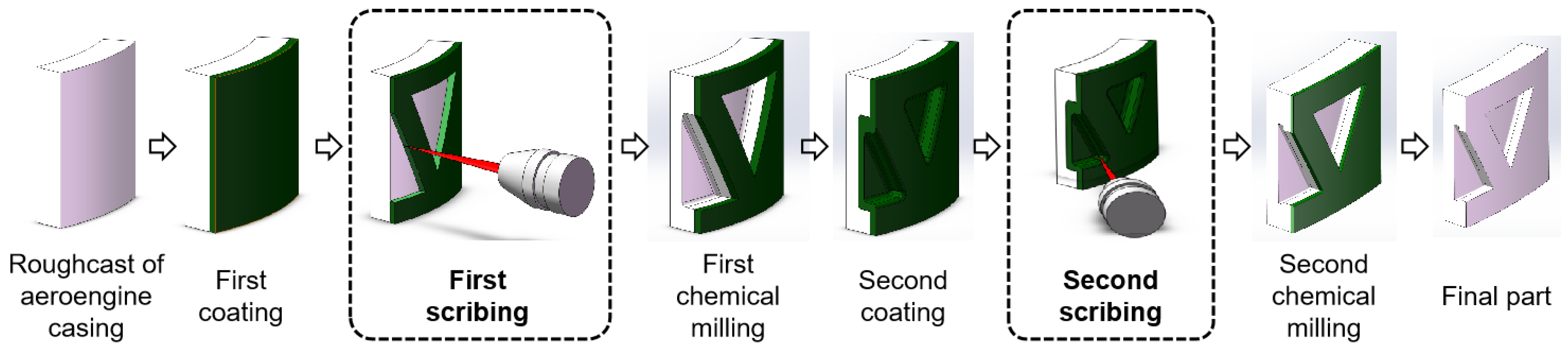
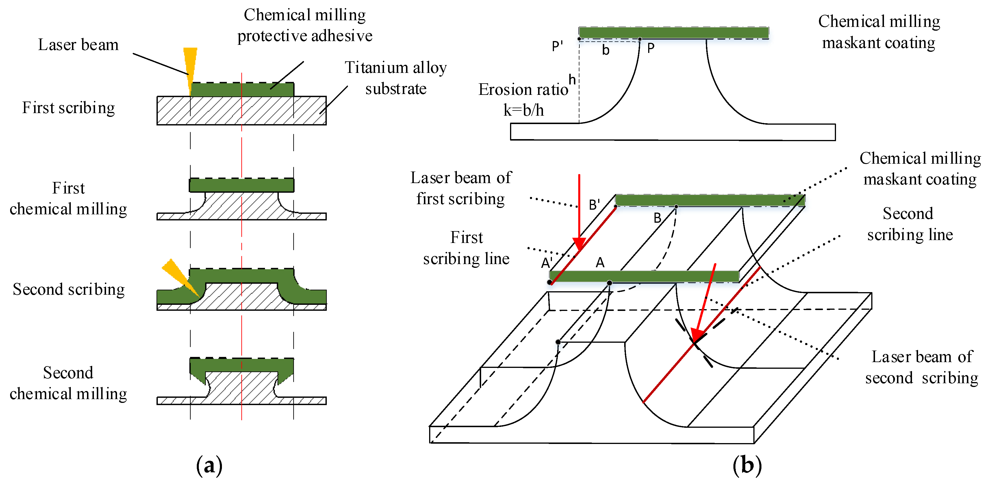
As an important process in chemical milling, the laser scribing process has an important effect on the quality of milling parts. In aerospace chemical milling parts, a large number of reinforcing ribs are designed as “I-shape” or “T-shape” structures to maximize weight reduction while ensuring the strength and rigidity of the casing. The chemical milling process of parts includes: chemical degreasing, sand blowing, coating maskant, scribing, uncovering maskant and chemical milling [29,30]. The laser scribing process of the engine casing is as follows [31]: (1) The blank part is coated with maskant after chemical degreasing and sand blowing; (2) First scribing according to the engraved pattern; (3) First chemical milling; (4) The part is secondly coated with maskant; (5) Second scribing according to the engraved pattern; (6) Second chemical milling; (7) Obtaining the final part. The chemical milling process of aeroengine casing parts is shown in Figure 1.
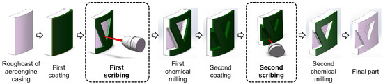
Figure 1.
Manufacturing process of chemical milling parts.
In the scribing process of chemical milling parts, there are obvious differences in the actual patterns between the first and second scribing. The laser beam is generally perpendicular to the surface of the cylinder in first scribing. The second scribing is on the sidewall of the stiffener, which formed the approximate arc surface after the first chemical milling. In second scribing, the laser beam must be inclined to etch with the sidewall of the stiffener section, as shown in Figure 2. Compared with first laser scribing on two-dimensional plane parts, the biggest characteristic of second scribing on three-dimensional parts is the change of “laser beam direction”. During first laser scribing on two-dimensional plane parts, the direction of the laser beam is always perpendicular to the plane, which is always in a vertical position and consistent with the direction of gravity. In second scribing on three-dimensional parts, the scribing surface is no longer on a horizontal plane, and the direction of the laser beam and gravity is inconsistent. In order to ensure the scribing quality and laser absorption rate, it is usually required that the laser beam is perpendicular to the workpiece surface. The angle between the laser incident direction and the vertical direction is defined as “θ”, which is changed with the surface shape of the workpiece. Therefore, it is of great significance to study the influence of the laser scribing angle on scribing depth to ensure the quality and accuracy of first/second scribing.
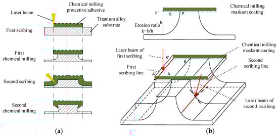
Figure 2.
Section diagram of laser scribing. (a) Schematic diagram of stiffener for laser scribing; (b) Schematic diagram of twice laser scribing.
The requirements of scribing are as follows:
- (1)
- The maskant scribing with the substrate should not be damaged;
- (2)
- The scribing lines are generally complex curves;
- (3)
- First laser scribing needs to be perpendicular to the part surface according to the pattern;
- (4)
- Second laser scribing needs to be inclined to the sidewall, which is generated by first chemical milling;
- (5)
- The upper and lower edges of the scribing lines are continuous and smooth, with high accuracy;
- (6)
- The accuracy of second scribing is ±0.05 mm.
2.2. Laser Scribing Features and Trajectories
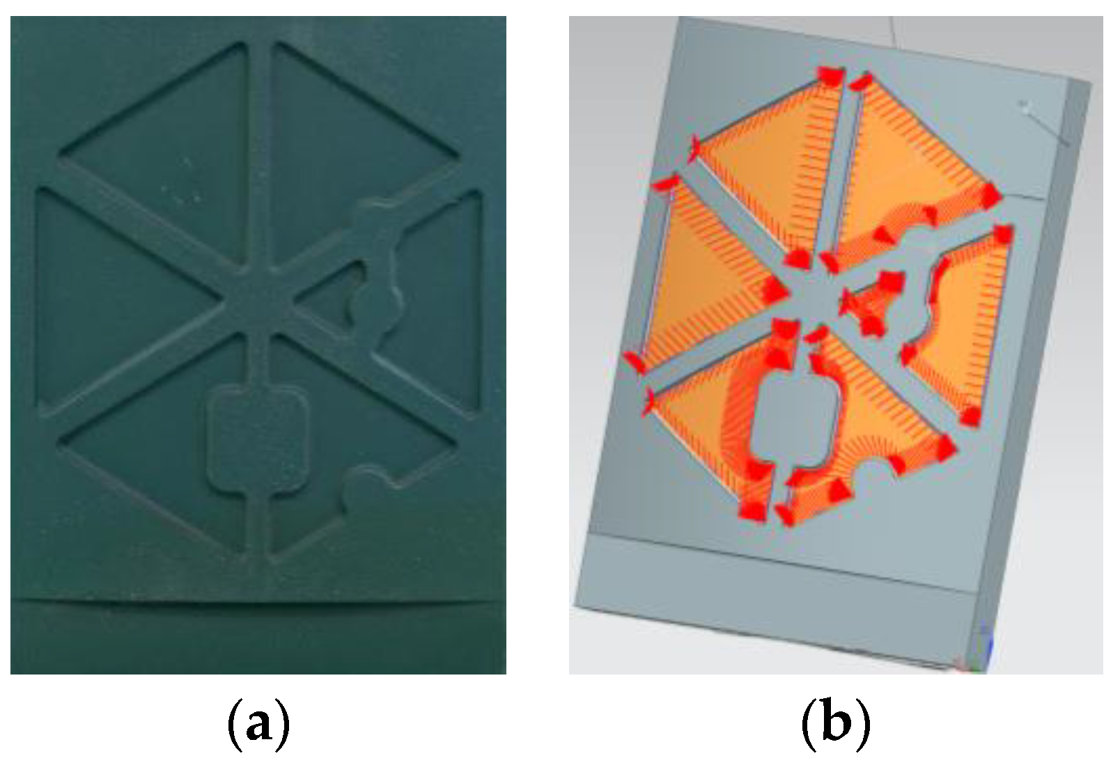
Since the aerospace thin-walled parts of chemical milling usually have complex pattern features, the laser scribing process needs to control the laser beam to move on the curved surface according to a given space curve trajectory, which is also needed to control the laser beam to maintain a given angle with the curved surface. The second scribing trajectory of aerospace parts local features is shown in Figure 3. Especially in the second scribing, the inclination angle of the laser scribing axis must be controlled in linkage to ensure the formation of I-shaped ribs by chemical milling. The laser first and second scribing is shown in Figure 4.

Figure 3.
Local pattern features of aeroengine casing and Second scribing trajectory. (a) Local pattern features of aeroengine casing; (b) Second scribing trajectory of aerospace parts local features.
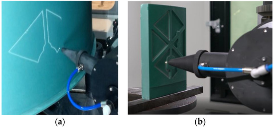
Figure 4.
Laser first scribing and second scribing. (a) Laser first scribing on aeroengine casing parts; (b) Second scribing on local feature parts of aeroengine casing.
2.3. Laser Scribing Quality
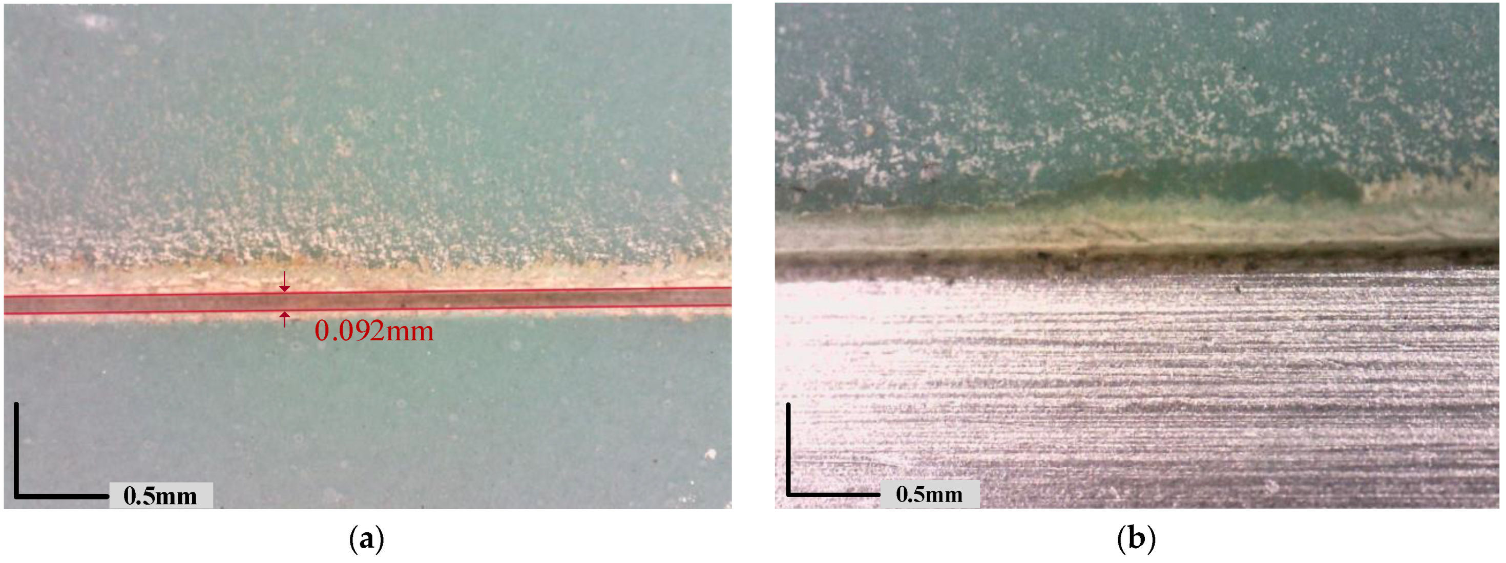
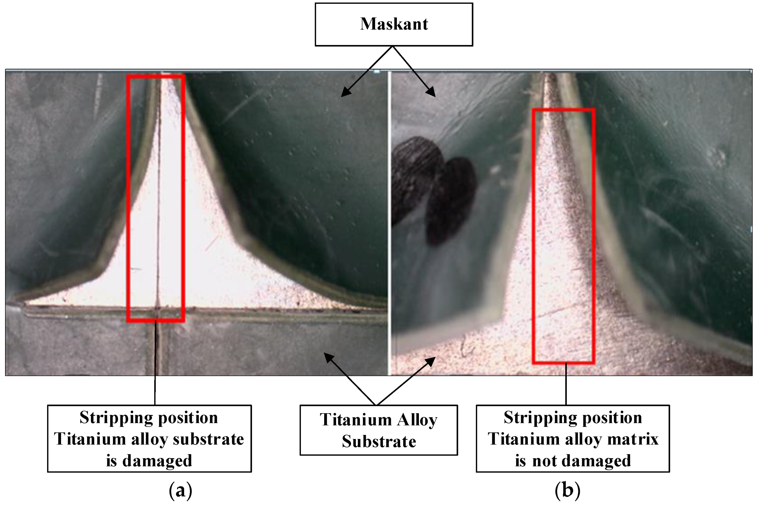
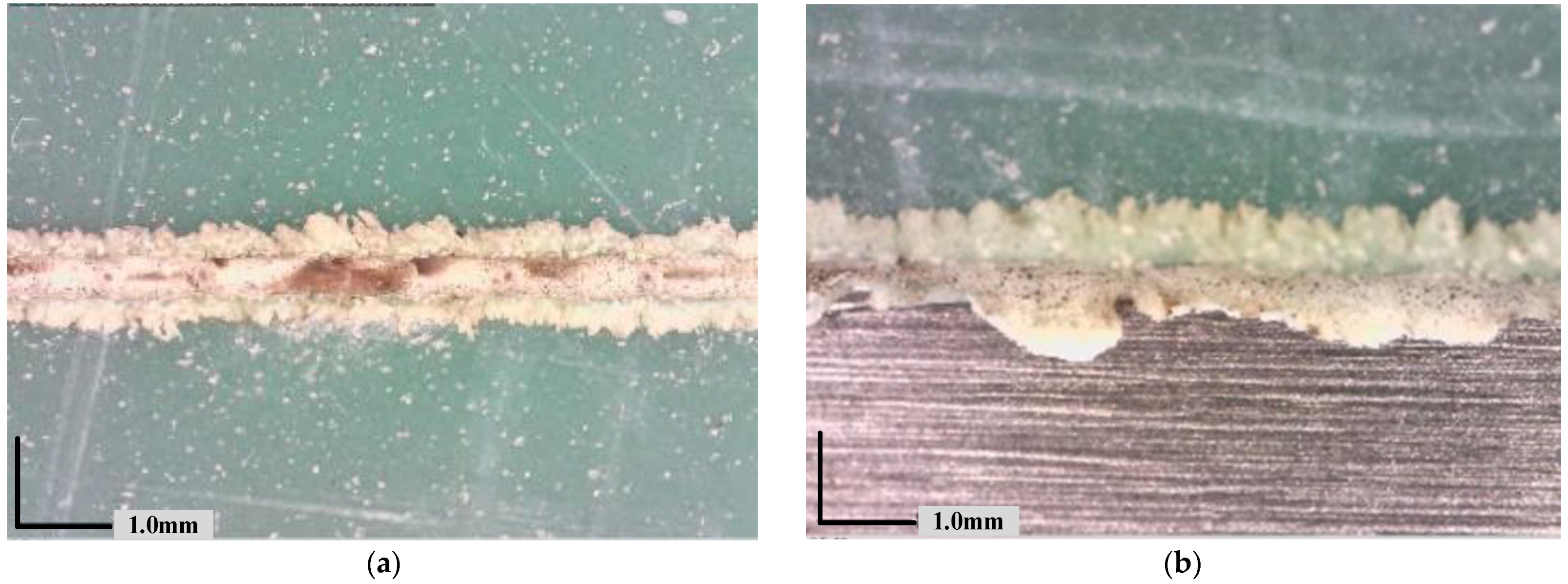
In laser scribing, appropriate laser parameters and motion parameters must be selected to realize ideal the ideal scribing quality. The ideal quality of first and second scribing are shown in Figure 5 and Figure 6. When the laser ablation energy is too high, the titanium alloy matrix is ablated into visible grooves, as is shown in Figure 7. When the laser energy is too low, the maskant cannot be completely engraved. In the process of stripping maskant, the precision of the scribing line will be very poor, as shown in Figure 8, which will affect the precision of subsequent chemical milling.

Figure 5.
Good quality of laser scribing and stripping. (a) Width of laser scribing; (b) Edge quality of the laser.

Figure 6.
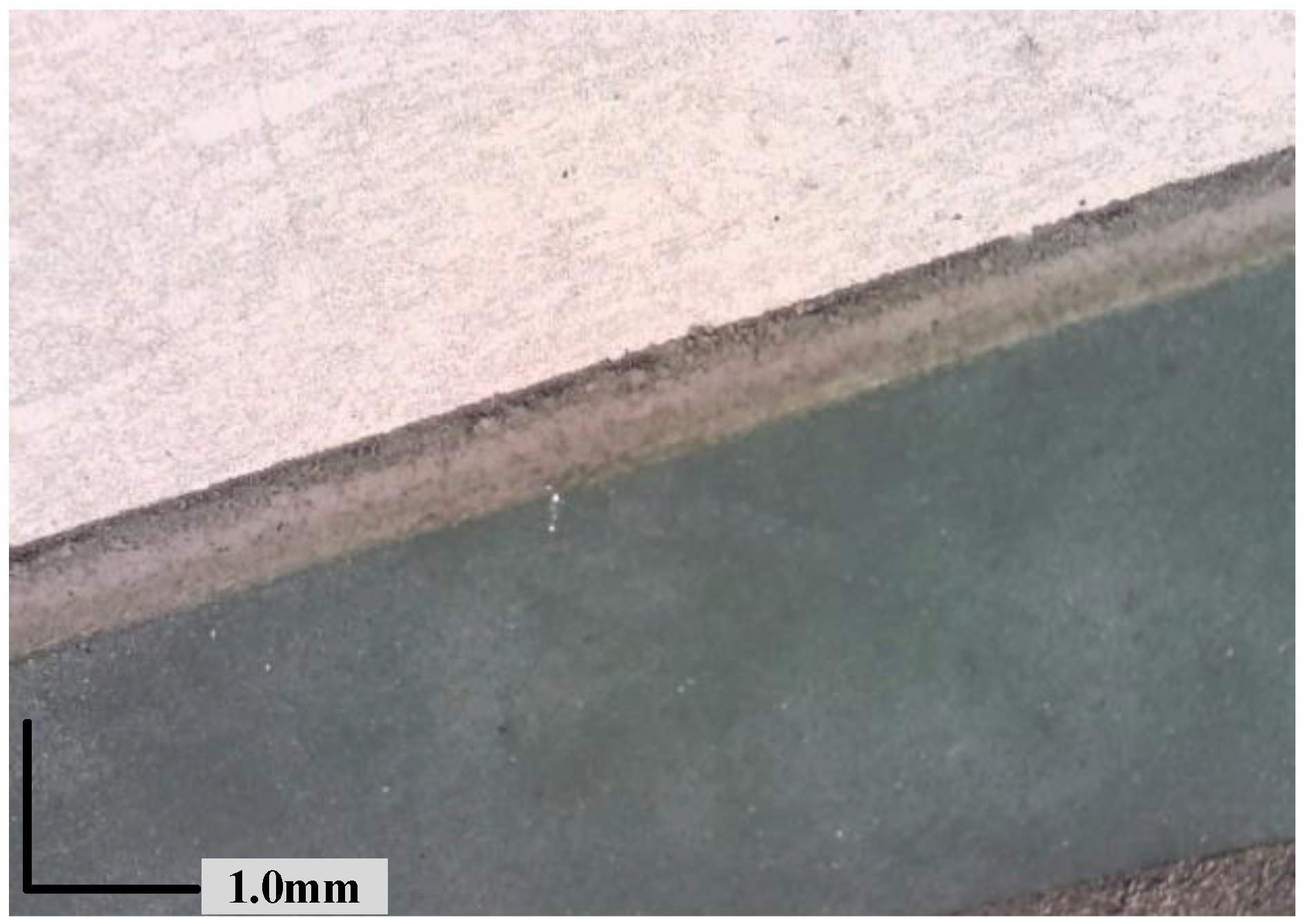
Laser grooving and removing chemical milling maskant of second scribing.
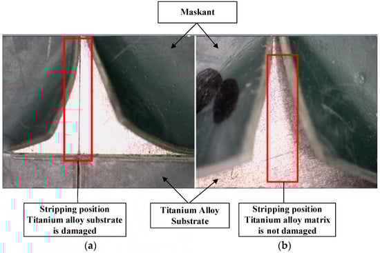
Figure 7.
Ablation of the substrate in laser scribing. (a) The titanium alloy substrate is damaged. (b) The titanium alloy substrate is not damaged.
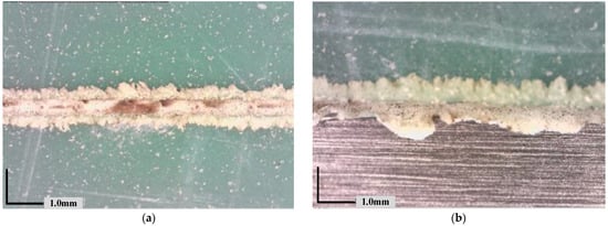
Figure 8.
The maskant incomplete cut. (a) Incomplete cut scribing line; (b) The scribing lines are not continuous and smooth.
3. Laser Scribing Mechanism and Theoretical Model
3.1. Mechanism and Process Parameters of Laser Scribing
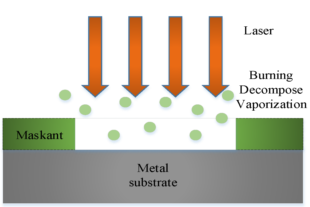
Laser scribing is a laser application based on laser ablation, which irradiates a high-energy laser beam on a maskant of parts to remove the maskant on the metal surface without damaging the substrate. The main mechanism of laser scribing is the ablation effect, which means the thermal effect generated by the high-energy laser to eliminate the combination of the maskant and the substrate by evaporation, plume, ionization and explosion [32]. The mechanism of laser scribing is shown in Figure 9.
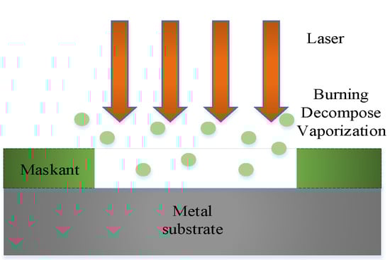
Figure 9.
Mechanism of laser scribing.
The main components of chemical milling maskant are organic polymers and is similar to plastic, resin or rubber, which have very high laser absorptivity at a 10.6 um wavelength. The thermal conductivity of organic polymer materials is much less conductive to heat than metals, and the heat conduction loss in processing is also very low. Among them, the thermal conductivity of resin glass is 1.9 × 10⁻¹ W/(m·K), the thermal conductivity of rubber is 1.69 × 10⁻¹ W/(m·K), and the thermal conductivity of titanium λ = 15.24 W/(m·K) [33]. Due to the poor thermal conductivity of organic polymers, there is an obvious temperature difference between laser heating areas and non-heating areas. On the premise of no energy accumulation, it can ensure that the processing slit width and heat affected area is small. In most cases, the basic optical properties of polymers are not only determined by polymer macromolecules but also have a decisive relationship with added materials such as dyes and softeners.
The laser scribing quality under argon protection/no argon protection is compared for AC850 protective maskant. The results show that there was little difference in the quality of laser scribing under argon protection and without argon protection [17]. According to the laser ablation mechanism of organic polymers, the phase transition of laser scribing from a solid state to a gas excited state is carried out by chemical decomposition [30]. Additionally, the complex macromolecules break down into smaller molecules, volatile elements and vapors. Therefore, the laser scribing mechanism of the AC850 maskant is mainly vaporization or sublimation after material decomposition.
3.2. Theoretical Model of Laser Scribing
In order to avoid the problems of incomplete penetration, excessive ablation or serious heat-affected zone in the process of laser scribing and reduce the consistency of scribing quality, the scribing depth model should be studied and established.
3.2.1. Theoretical Model of Laser Scribing
It is assumed that the transfer of laser energy in the material only exists in the direction perpendicular to the workpiece surface (defined as Z direction), and approximately conforms to the one-dimensional heat transfer equation. According to Lambert’s law, the laser intensity attenuates and propagates along the depth z inside the material is as follows:
According to the basic theory of thermodynamics, to evaporate or vaporize the material with a thickness of h, it is necessary to heat the material with a depth of h on the surface to the melting or even vaporization temperature. Since the interaction process between laser and materials conforms to the energy conservation, the energy balance of the scribing process at the scribing line can be described as follows [34]:
where,
is the reflectivity of the material surface;
is the laser power radiated on the surface of the material;
is the material density;
is the scribing speed;
is the scribing width;
is the scribing depth;
is the specific heat capacity of the material;
is the melting temperature of the material;
is the environmental temperature of the material;
is the melting enthalpy of the material;
is the evaporation enthalpy of the material;
is the heat conduction loss in the scribing area.
The left side of Formula (2) is the laser power absorbed by the material on the surface. On the right side of Formula (2) is the sum of the power required to heat the environment temperature to the evaporation temperature, the power required for melting and evaporation at the incision and the heat conduction loss.
If all the materials at the scribing area are sublimated, the sublimation enthalpy required for the transformation from a solid state to a gaseous state includes melting enthalpy and evaporation enthalpy. The above energy balance formula is effective for the phenomenon of incision.
Under the irradiation of a laser beam, if the workpiece material is chemically decomposed, is replaced by the specific enthalpy of decomposition. At this time, the sublimation temperature, evaporation temperature , is replaced by the decomposition temperature .
In this theoretical model, it is assumed that the laser scribing line is the same width of the upper and lower scribing seams of the section. In the actual scribing process, the section is generally a conical groove, and the actual cribbing width in Formula (2) can be approximately .
The following relationship between ablation depth and power density threshold is as follows:
is the power density threshold.
When the laser energy irradiates the material surface and is partially absorbed by the material, the energy of the part greater than the ablation threshold makes the material evaporate or even vaporize with thickness h, the energy balance relationship is as follows:
The above formula can be transformed as follows:
In general, the laser output power is equal to the power of the material surface, that is . is the laser average output power. When the material is assumed to be isotropic, the ablation power density of the material , the material density , the melting enthalpy of the material and the evaporation enthalpy of the material are constants. Therefore, the ablation depth is determined by the material absorptivity , laser power , scribing speed , which is based on Formula (5).
3.2.2. Cumulative Scribing Depth Model of Pulsed Laser
In the scribing process of a pulsed laser, the energy conservation Formula (2) can be expressed as:
is the single pulse energy;
is the displacement distance of two pulses.
Where,
For a quasi-continuous pulse laser, the calculation formula of the single pulse energy is:
where:
is peak power;
is pulse frequency;
is duty cycle.
The laser output power per unit time is:
Substitute Formulas (7) and (8) into Formula (6):
Formula (10) can be simplified as:
Substitute Formula (12) for Formula (11), the model equation is as follows:
When , Formula (2) is exactly the same as Formula (13). Therefore, the laser frequency only changes the single pulse energy but does not change the average laser output power. The laser power is mainly determined by the duty cycle and peak power.
It is generally believed that one pulse interval is sufficient for heat transfer; all ablation products and excess heat can be blown away by auxiliary gas. Therefore, it is assumed that the removal rate of the material will not be affected by the action of the previous pulse. It should be noted that during the processing of the quasi-continuous laser, if the laser frequency is too large and the pulse time interval is too small, all ablation products and excess heat are difficult to be blown away by auxiliary gas, there may be overheating in the process of laser radiation processing. Overheating leads to the accumulation of the edges of laser scribing, resulting in the irregular edges of laser scribing lines, which affects the final scribing quality.
4. Laser Scribing Machine and Parameters of Experiment
4.1. Laser Scribing Machine
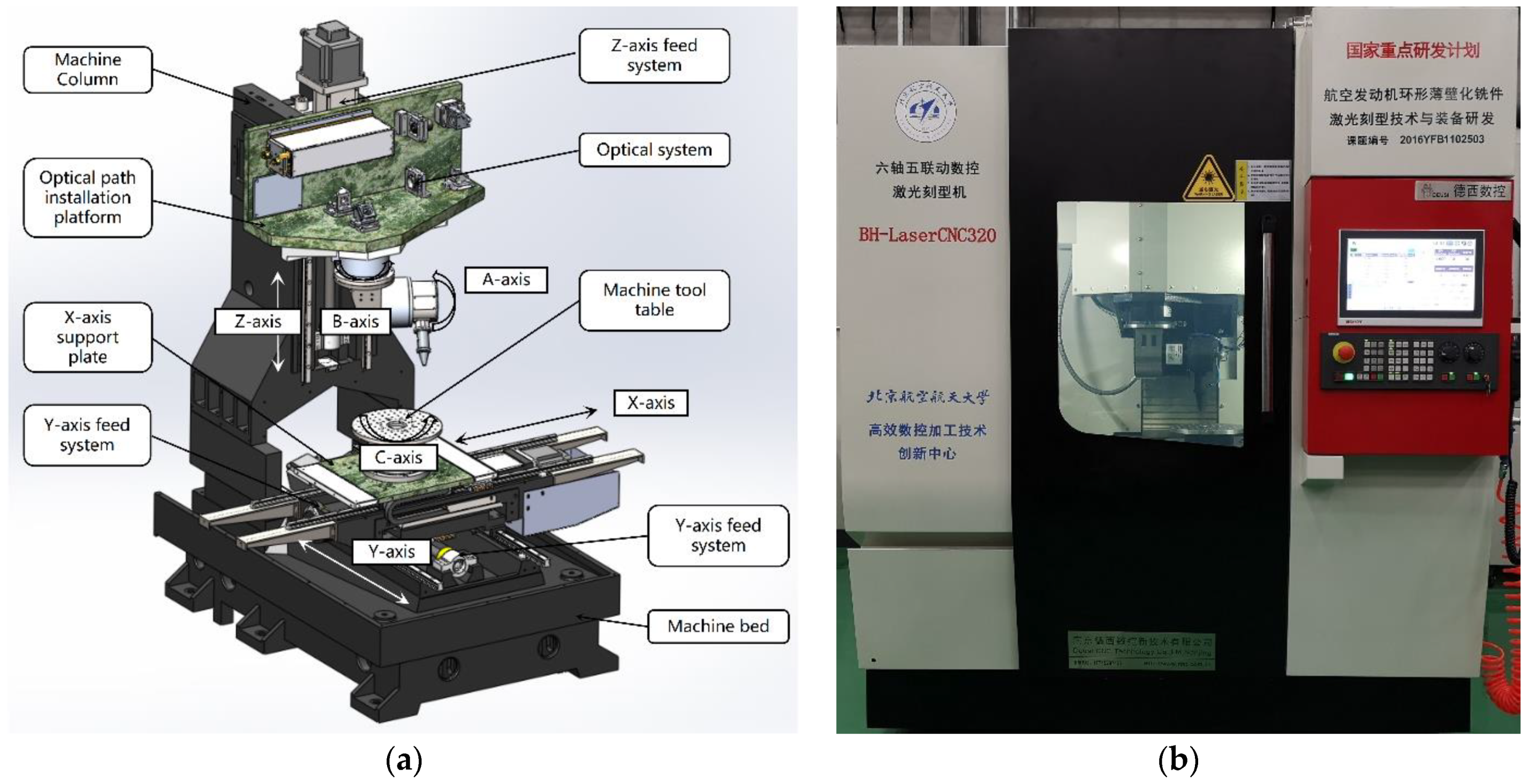
The laser scribing machine used in the test is a prototype of a six-axis five-linkage intelligent NC laser scribing machine tool, which is shown in Figure 10. Figure 10a show the structural principle and composition of the host machine. The main components include: machine bed and column, optical path installation platform, X/Y/Z linear feed axis, a/b optical rotation axis, c-axis mechanical rotation axis workbench, laser and optical path system, etc. In the process of laser scribing, due to the evaporation of the material inside the incision, the inert gas beam coaxial with the laser beam is often used to protect the optical system in the processing head, which can avoid contamination and oxidation of the workpiece.
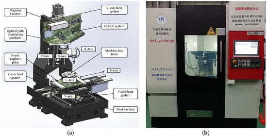
Figure 10.
Structure and equipment of laser scribing machine. (a) Structure of laser scribing machine; (b) 6-axis 5-linkage laser scribing machine.
The laser and optical transmission systems are as follows: (1) laser: Firestar V30 CO2 laser from SYNRAD. After the laser beam emitted by the CO2 laser is expanded by a beam expander, the position and direction of the laser beam are adjusted by reflector M1 and M2, and the beam is shaped through an aperture. The reflector quarter-wave plate adjusts the laser beam to the circular polarization state. After adjusting the direction and position of the laser beam with the reflector M3, the laser beam enters the AB axis laser processing head and converges to the working surface through the focusing mirror for scribing processing. Among them, the AB-axis laser processing head can achieve rotation of laser beam in three-dimensional space, the B-axis can make all optical elements behind it rotate 360° around the optical axis and the A-axis can make all optical elements behind it swing ±120° around the optical axis, which realize the precise positioning in spatial position and five-axis high-precision linkage of the optical path flexible space transmission positioning device in the five-axis machining system. The laser uses the SIMATIC S7-1200 module from Siemens, Berlin and Munich, Germany to output the PWM impulse signal to control the output of the CO2 laser, so the CO2 laser is a quasi-continuous laser. It should be noted that after the beam passes through the focusing mirror, the parallel polarized light emitted by the laser becomes circularly polarized. The laser and optical path parameters are shown in Table 1.

Table 1.
Laser and optical path parameters.
4.2. Experiment Parameters
The specification of the experiment plate with TC4 as base material is 300 mm × 200 mm × 2 mm, and its surface is covered with AC850 protective adhesive. According to the actual process requirements of laser scribing, the coating layer of laser scribing protective adhesive is 0.6 mm, which is uniform overall, and the color of AC850 protective adhesive is dark green. The scribing depth is measured by a super-high magnification lens zoom 3D microscope (Equipment model: Olympus dsx1000). The experiment plate is placed horizontally on the C-axis turntable, and the incident angle of the laser is changed by controlling the A/B rotation axis to complete the experimental processing. The test parameters of laser scribing is shown in Table 2.
Table 2.
Test parameters of laser scribing.
The output of the CO2 laser is controlled by the Siemens SIMATIC S7-1200 module by using a PWM pulse signal. In order to accurately measure the influence of laser power on the scribing depth, the actual average power of different duty cycles is measured at the pulse frequency of 1000 Hz, as shown in Table 3.
Table 3.
Actual average power under different duty cycles (effective measurement time 2.4 S).
Under the condition of a 9% duty cycle, the actual average power corresponding to different pulse frequencies is measured, as shown in Table 4. The minimum pulse time of the PWM module output is 1 μs. The different laser power at different frequencies is mainly due to the time constant of the PWM wave, which has a great influence on the duty cycle at different frequencies.
Table 4.
Actual average power under different pulse frequencies (effective measurement time: 2.4 S).
5. Results and Discussion
5.1. Verification and Analysis of Theoretical Model
According to the five groups of laser scribing parameters in Table 2, the experimental processing is carried out on the laser scribing equipment described in this paper. The depth of different positions of laser scribing under each processing parameter is measured seven times, and the laser experimental data and theoretical model are analyzed according to the measured depth data.
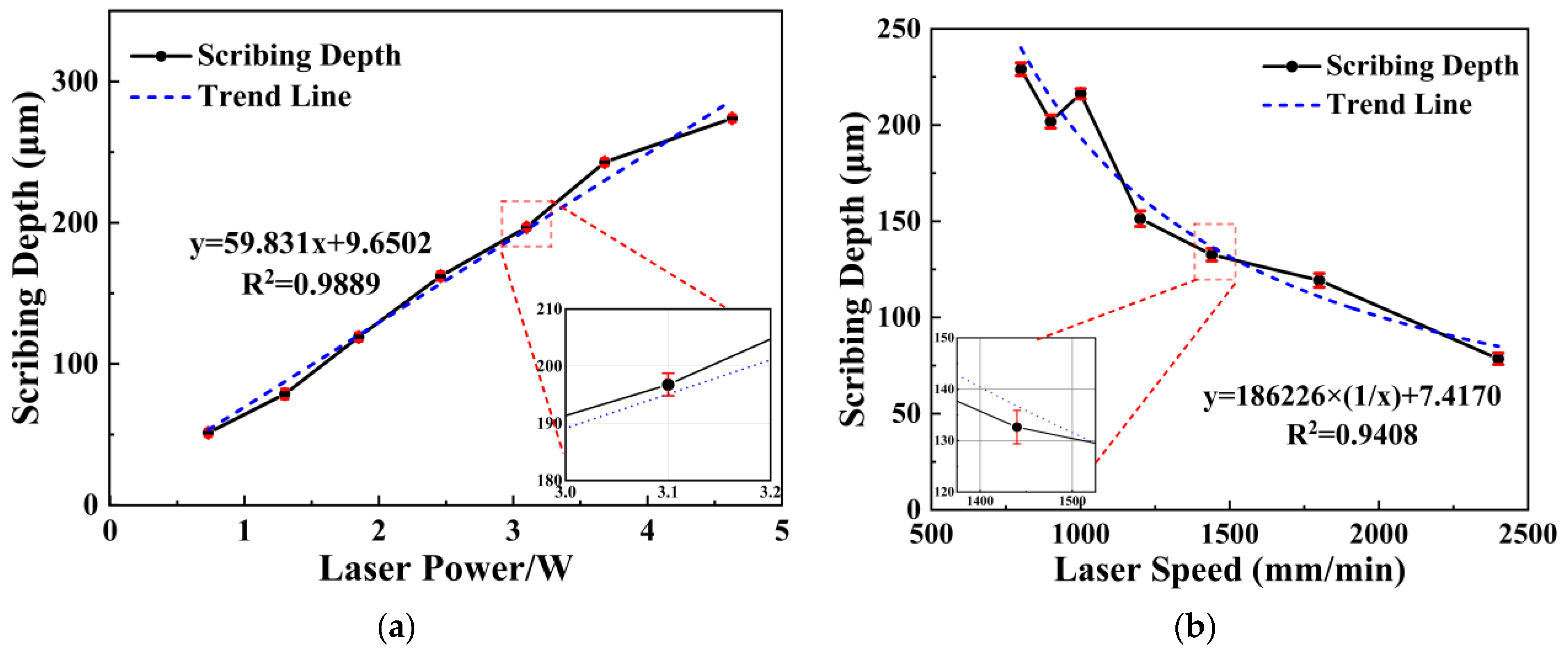
The relationship between laser power and scribing depth is as shown in Figure 11a. There is an obvious linear positive correlation between laser power and scribing depth, which conforms to the model of Formula (5).
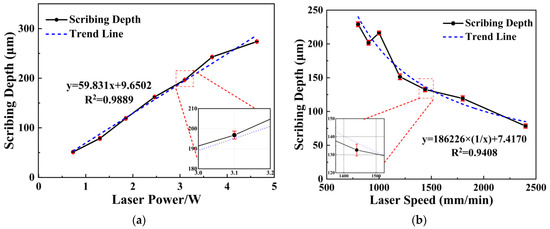
Figure 11.
Relationship between laser power and speed with scribing depth. (a) Relationship between scribing power and scribing depth; (b) Relationship between scribing speed and scribing depth.
The relationship between laser speed and scribing depth is as shown in Figure 11b. There is an obvious inverse proportionality between laser speed and scribing depth, which also conforms to the model of Formula (5).
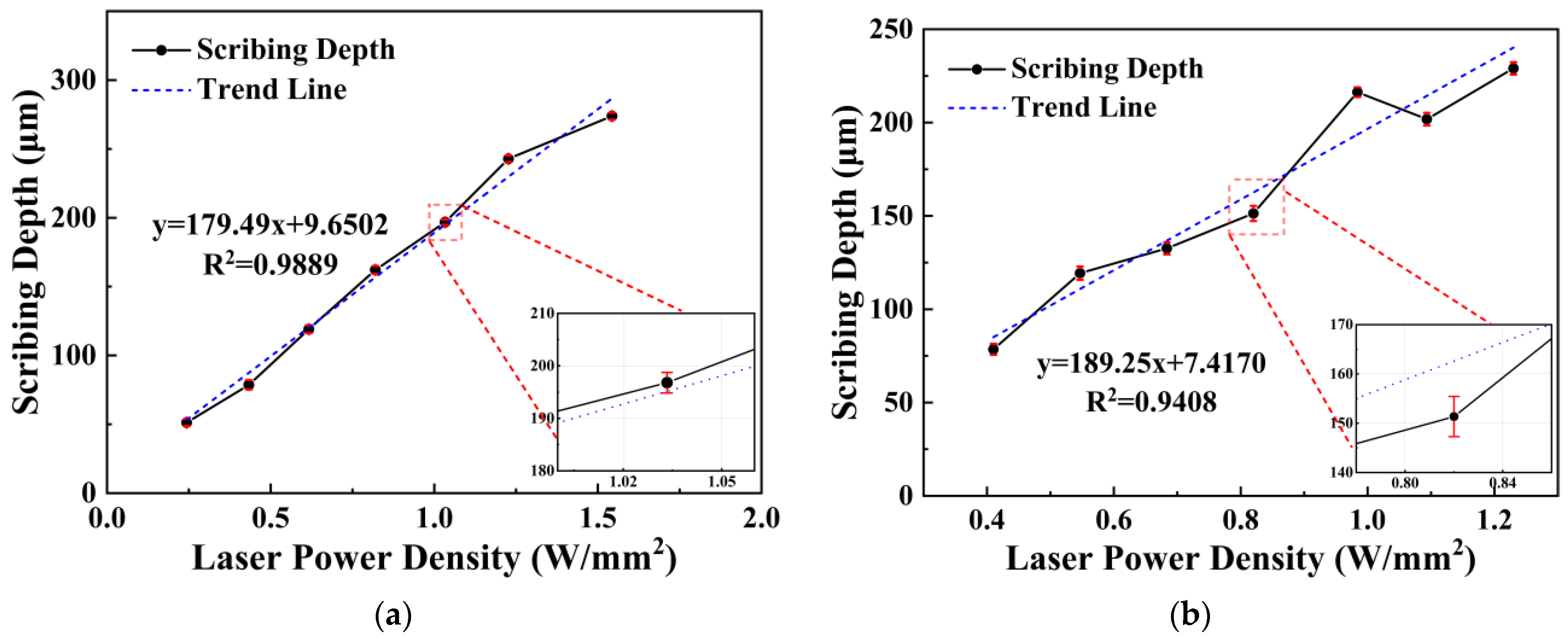
According to the scribing depth data under different laser power and speed in Figure 11, the corresponding laser power density can be calculated, respectively. The relationship between laser scribing depth and power density can be established, as shown in Figure 12.
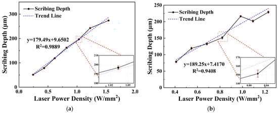
Figure 12.
Relationship between laser power density and scribing depth. (a) Relationship between laser power density and scribing depth based on a single factor experimental data of laser power; (b) Relationship between laser power density and scribing depth based on a single factor experimental data of laser speed.
As shown in Figure 12, there is an obvious linear positive correlation between the laser scribing depth and the laser power density, and the calculated trend lines are also very similar. Therefore, the relationship between the laser scribing width and the required laser power density can be expressed by formula:
This formula is a simplified expression of Equation (5), which is the theoretical model of laser scribing. In the application of laser scribing, when the depth of laser scribing is given, the above formula can be recognized by the NC system. At this time, the laser power can be adjusted adaptively according to the laser speed so as to realize the accurate control of the scribing depth in the NC laser scribing.
The data of the testing set were simulated to verify the accuracy of proposed mathematical equations, which is shown in Table 5. The prediction accuracy is defined as follows [35]:
where PV and MV are the prediction value and measurement value.
Table 5.
Prediction results of testing set data.
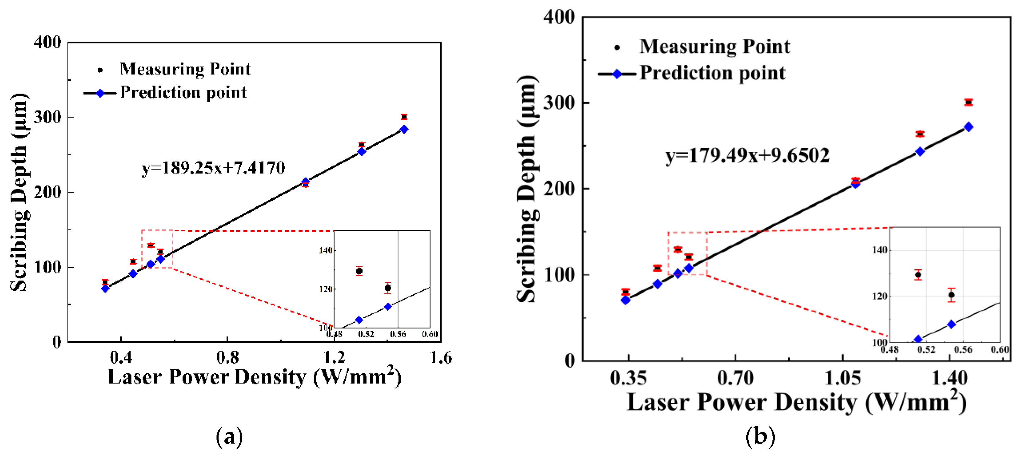
According to mathematical Equation (13), the minimum accuracy of the prediction equation is 78.36%, the maximum value is 98.07% and the average prediction accuracy is 88.53%. The accuracy of mathematical Equation (13) at different test points is shown in Figure 13a.
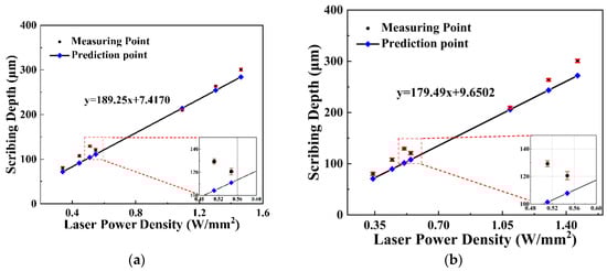
Figure 13.
Accuracy of mathematical equations. (a) Accuracy of mathematical Equation (13); (b) Accuracy of mathematical Equation (14).
According to mathematical Equation (14), the minimum accuracy of the prediction equation is 80.49%, the maximum value is 97.91% and the average prediction accuracy is 90.79%. The accuracy of mathematical Equation (13) at different test points is shown in Figure 13b.
5.2. Influence and Analysis of Frequency on Scribing Depth
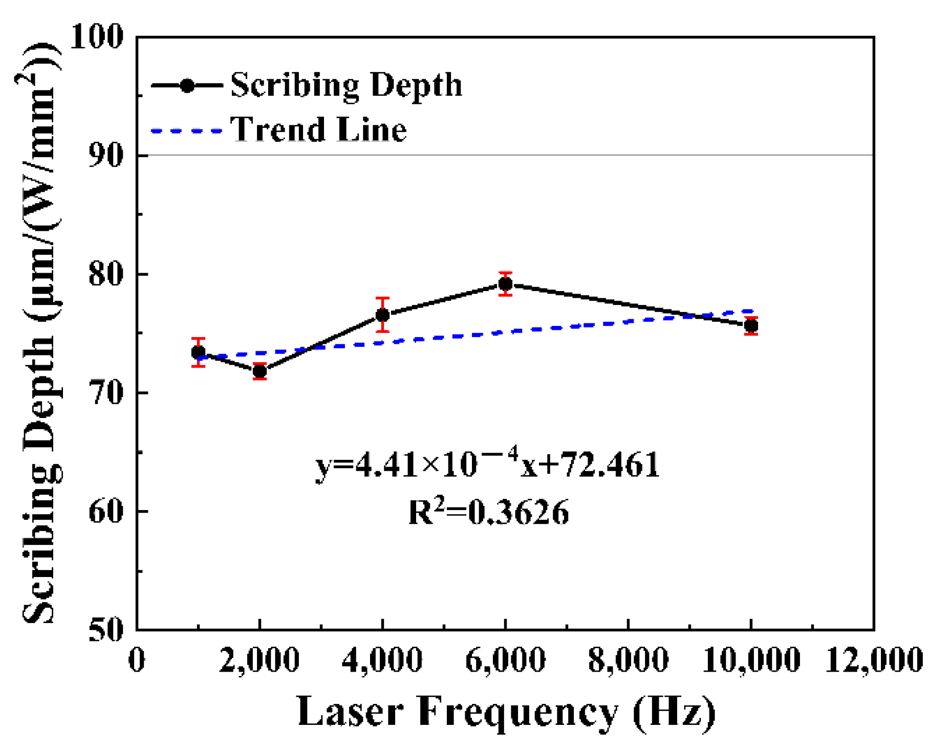
According to the corresponding data of laser power and scribing depth under different laser frequencies, the laser scribing depth under unit power is calculated; that is, the scribing depth/the laser power under different frequencies. The scribing depth per unit power corresponding to different frequencies is calculated, as shown in Figure 14.
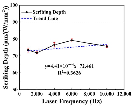
Figure 14.
Relationship between laser frequency density and scribing depth.
According to the trend line in Figure 11, the linear coefficient is 4.41 × 10⁻⁴. The laser frequency has little effect on the scribing depth. This result is also consistent with the theoretical model of laser scribing. It should be noted that the heat accumulation of the previous pulse cannot be completely eliminated with the increase of frequency, which will increase the material temperature of the current laser scribing. When the laser parameters remain unchanged, the same laser influence will remove more materials.
The laser frequency will also affect the scribing speed and accuracy based on the laser overlap rate. If the pulse overlap rate is not selected properly, it will lead to the phenomenon of “sawtooth” at the edge of the maskant layer, and the width of the scribing line cannot be guaranteed.
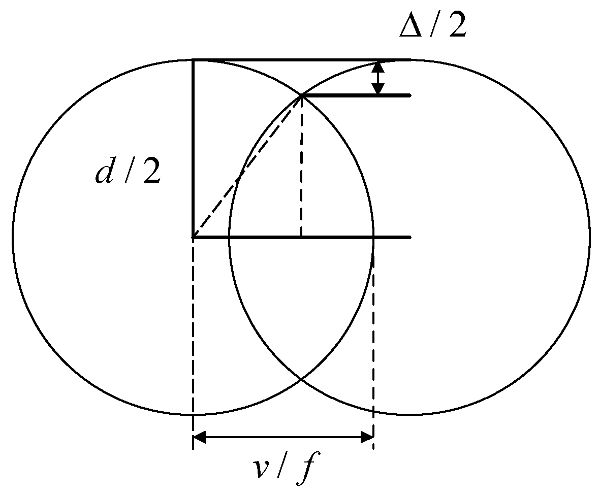
The formula of laser scribing line accuracy, speed and frequency is shown in Equation (17). The overlap rate and residual height of ablation width are shown in Figure 15:
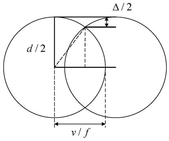
Figure 15.
Overlap rate and residual height of ablation width.
is the residual height of ablation width;
is the laser scribing speed;
is the laser spot diameter;
is the laser frequency.
5.3. Experimental Results and Analysis of Laser Scribing Depth with Laser Incidence Angle
5.3.1. Result of Forward Angle
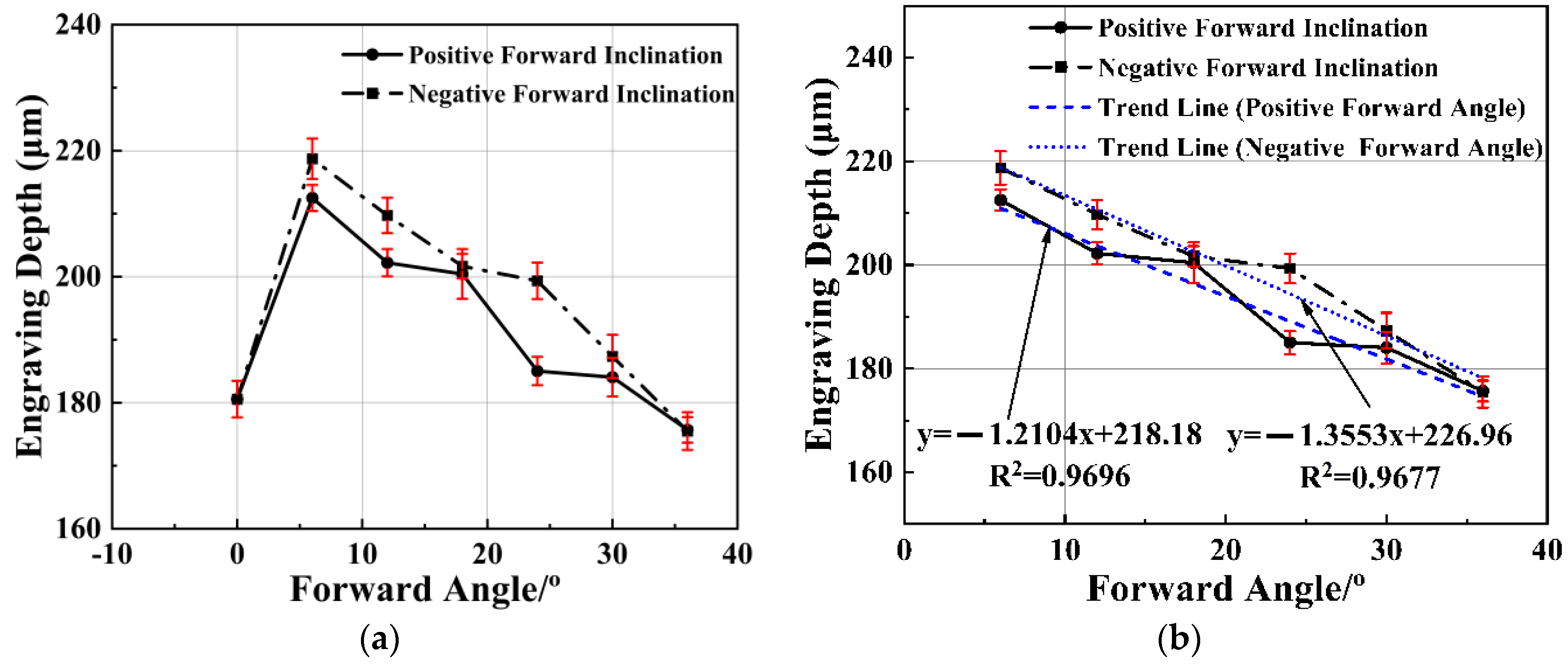
Under the given laser power, speed and frequency parameters, the depth of laser scribing at vertical incidence angle is smaller than the depth of laser scribing at ±6° forward angles, as shown in the first and second points in Figure 16a. With the increasing of the forward angle in the positive and negative directions, the scribing depth decreases linearly, as shown in Figure 16b.
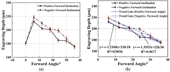
Figure 16.
Relationship between forward angle and scribing depth. (a) Relationship between positive/negative forward inclination and scribing depth. (b) Relationship between positive/negative forward inclination and scribing depth without vertical angle.
5.3.2. Result of Side Slope Angle
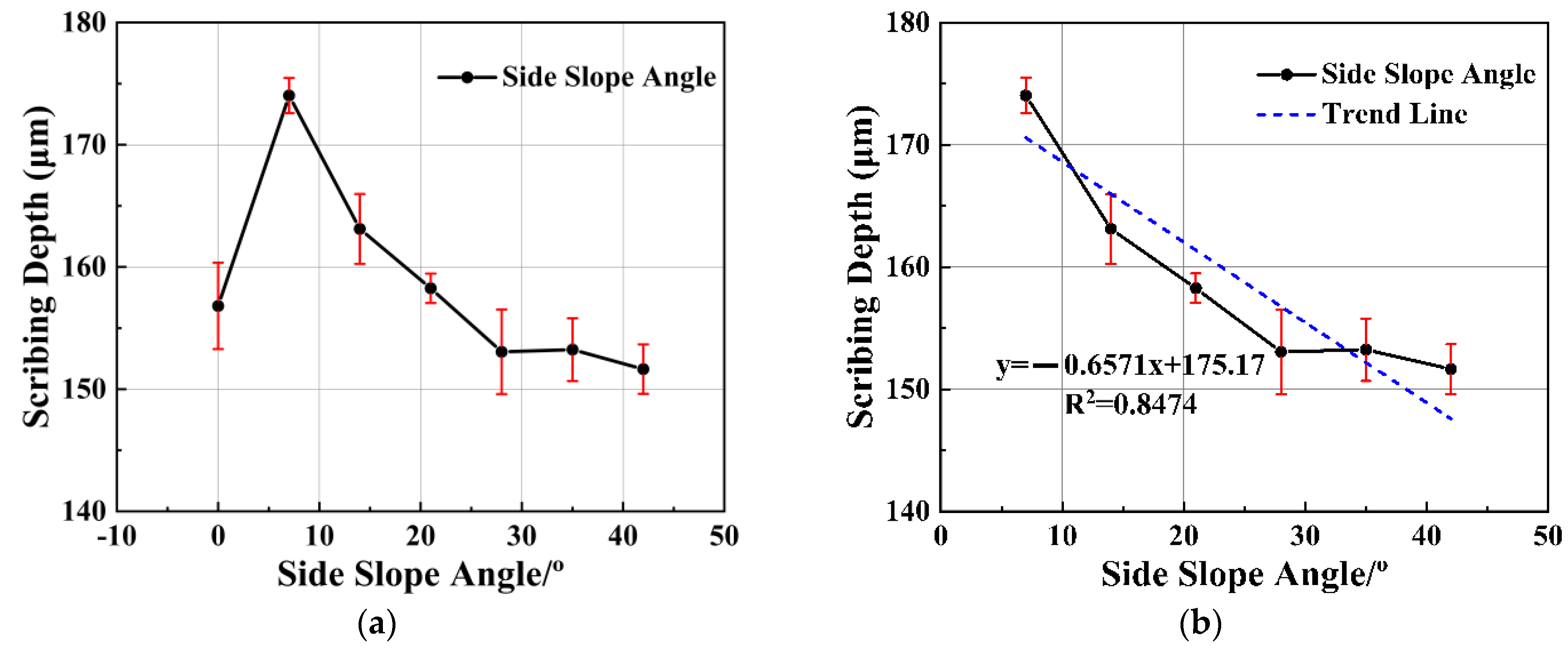
Under the given laser power, speed and frequency parameters, the depth of laser scribing at vertical incidence angle is smaller than the depth of laser scribing at ±7°side slope angle, as shown in the first and second points in Figure 17a. With the increase of the side slope angle increases in the positive and negative directions, the scribing depth decreases linearly, as shown in Figure 17b.
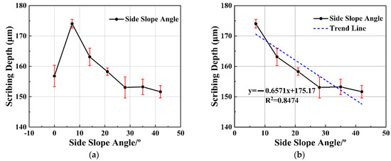
Figure 17.
Relationship between side slope angle and scribing depth. (a) Relationship between side slope angle and scribing depth. (b) Relationship between side slope angle and scribing depth without vertical angle.
5.3.3. Discussion of Laser Scribing Depth with Laser Incidence Angle
According to the laser scribing depth of the forward angle and side slope angle under the same power density, and according to Figure 16b and Figure 17b, the relation equation between the laser scribing depth and scribing angle can be established. According to the equation, the laser scribing depth at different angles can be predicted, which can be effectively applied to the laser secondary scribing. Meanwhile, there are two obvious phenomena: (1) the scribing depth at the forward angle (6°) and side slope angle (7°) are increased compared with the vertical incidence angle; (2) the scribing depth decreases linearly with the increase of incident angle.
(1) Discussion of scribing depth improving by laser incident angle.
According to Formula (5), the increase of laser scribing depth must be a change in the power absorbed by the material under the condition that other process parameters remain unchanged. In laser scribing, a large number of maskant particles, molecules and ions are splashed out from the surface of the matrix. Additionally, white fumes were observed during the experiment. As a kind of polymer material, chemical milling maskant inevitably produces fumes which leads to the loss of laser energy in the process of interaction with laser. The laser energy loss depends on the density of the particles in the fumes and the length of the fumes along the laser propagation direction. The loss of laser energy can be expressed as:
where,
is the laser power on the surface of the material;
is the laser output power;
is the laser power irradiating on the fumes;
is the absorption coefficient of a laser incident to the fumes;
is the length of the fumes in the direction of the laser beam.
The laser incident angle can change the fumes concentration in the direction of laser transmission and can also change the length of fumes in the direction of laser transmission. In the process of laser scribing, the material will go through the whole process of material evaporation, plume formation and smoke formation. This phenomenon is quite complex, and a full computational fluid dynamics (CFD) simulation would be needed in order to really evaluate its effects. The evaluation of the plume needed advanced thermochemical non-equilibrium [36]. According to the literature, the reverse jet of laser ablation plume first occurs in the ablation plane and gradually diffuses around with time, but the density and temperature also gradually decrease [37]. This will cause relatively more fumes in the vertical direction. Considering that the flow speed of smoke is not enough to be completely blown away, it will have an impact on the energy actually irradiated on the material surface. The plume in the process of laser scribing is not the goal of this paper, and we only made a brief discussion and analysis.
(2) Analysis of scribing depth decrease with increasing laser incidence angle.
Aiming at the problem that the laser scribing depth decreases with the increase of angle, there are three kinds of influences jointly affecting this trend. Based on Formula (5), including the material reflectivity R, scribing width and heat conduction loss .
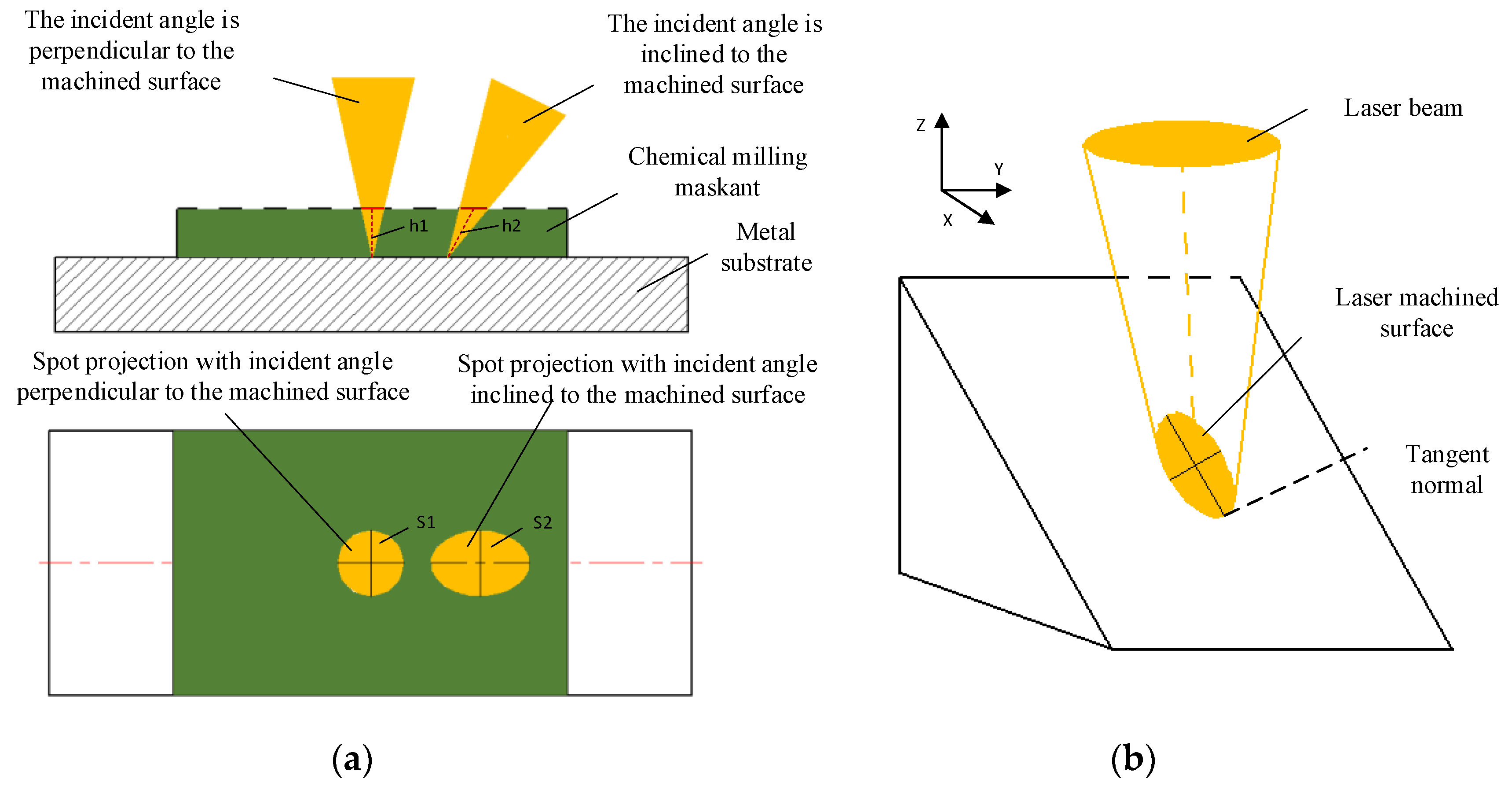
The relationship between reflectivity R and inclination θ of materials can be calculated by the Fresnel formula of the refraction law. When the incident angle is less than Brewster’s angle, the reflectivity of materials to circularly polarized light stays roughly the same. When the incident angle is greater than Brewster’s angle, the reflectivity of organic polymers to circularly polarized light increases rapidly until total reflection. The laser beam incidence angle has a great influence on the laser scribing area. With the change of the inclination angle θ of the laser beam, the radiation area of the laser becomes wider (S2 > S1), which is shown in Figure 18.
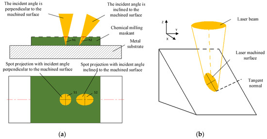
Figure 18.
The influence of laser angle. (a) The influence of laser beam incidence angle on depth and area; (b) 3D sketch of laser beam incidence angle on depth and area.
With the increase of laser scribing area, the laser power density decreases under the condition of invariable laser power, speed and frequency. It takes a longer time for the single-pulse laser energy to heat the material to the melting temperature, and heat transfer time becomes longer. As a result, the width of the scribing becomes larger with the increase of the heat-affected zone, and the loss of heat transfer energy in the whole process becomes larger. In summary, the above three parameters will lead to a decrease in the slit depth of laser scribing with the increase of incidence angle.
6. Conclusions and Future Work
(1) Based on the analysis of the process and difficulties of multiple laser scribing, this paper analyzes the process requirements of adaptive matching of laser scribing process parameters and motion parameters in the process of laser scribing. The physical theoretical model of scribing depth and laser scribing process parameters was established for a continuous laser and a quasi-continuous laser. Experimental results show that the theoretical model is in good agreement with experimental data. The laser scribing depth is positively proportional to the laser power and inversely proportional to the laser speed and has little relationship with the laser frequency.
(2) There is an obvious positive linear correlation with the laser power density. The predicted accuracy of mathematical equations regarding the laser power density and scribing depth which is calculated by the laser power, speed and scribing depths experimental data, are 88.53% and 90.79%. The relationship model of laser scribing depth with laser power and laser scribing speed can realize the adaptive adjustment of laser energy according to the laser speed so as to realize the precise control of scribing depth in the application.
(3) Under the condition of the same laser power, scribing speed and scribing frequency, the laser scribing depth at a forward angle of 6° and a side slope angle of 7° is the deepest compared with the vertical incident scribing depth, and the angle is also the recommended angle of laser scribing. With the increase of the incidence angle, the laser scribing depth will decrease linearly. The scribing depth at each angle can be conveniently calculated for practical laser scribing applications. The influence of laser scribing angle for scribing depth is also explained and analyzed, which includes many factors. Further systematic research is needed in the follow-up study.
In this paper, a laser sublimation model based on energy conservation is established, and the influence of laser engraving process parameters on engraving depth is analyzed only by a single factor. The techniques can be used to guide the setting of process parameters during laser scribing processing, which will help improve processing accuracy and efficiency. However, the comprehensive influence of multiple parameters in laser engraving also needs to be further analyzed and studied. Meanwhile, the theoretical model of incident angle and laser engraving depth also needs to be further studied. In the future, our group will conduct research on precise removal models and multiparameter regression methods of laser scribing, or even the influence of fumes and plumes, which is a more complex task.
Author Contributions
Conceptualization, Q.L. and J.W.; methodology, J.W., P.S. and Q.L.; validation, J.W. and P.S.; formal analysis, J.W.; investigation, P.S. and L.W.; data curation, P.S.; writing—original draft preparation, Z.N.; writing—review and editing, J.W. and Z.N.; visualization, J.W.; supervision, Q.L.; project administration, Q.L. All authors have read and agreed to the published version of the manuscript.
Funding
This research was funded by the project “Research and development of laser scribing technology and equipment for annular thin-walled milled parts of aeroengine” from the national key R&D plan “special project of additive manufacturing and laser manufacturing” (Project No.: 2016YFB1102500).
Institutional Review Board Statement
Not applicable.
Informed Consent Statement
Not applicable.
Data Availability Statement
Not applicable.
Acknowledgments
The authors acknowledge Li Ming from the Xi’an Institute of Optics and precision mechanics of CAS, and Wang Hui from AECC Shenyang Liming Aero-Engine Co. Ltd.
Conflicts of Interest
The authors declare no conflict of interest.
References
- Ezugwu, E.O.; Bonney, J.; Yamane, Y. An overview of the machinability of aeroengine alloys. J. Mater. Processing Technol. 2003, 134, 233–253. [Google Scholar] [CrossRef]
- DeForce, B.; Eden, T.J.; Pickering, H.W. Cold-Sprayed Aluminum Coatings for Magnesium Aircraft Components. Mater. Perform. 2009, 48, 40–44. [Google Scholar]
- Hansen, J.O.; Long, K.C.; Jackson, M.A.; Hodgens, H.M. Chemical Milling Process and Solution for Cast Titanium Alloys. U.S. Patent No. 6,793,838, 21 September 2004. [Google Scholar]
- Staebler, C.J., Jr. Advanced Chemical Milling Processes; Grumman Aerospace Corp.: Bethpage, NY, USA, 1971. [Google Scholar]
- Hot, J.; Dasque, A.; Topalov, J.; Mazars, V.; Ringot, E. Titanium valorization: From chemical milling baths to air depollution applications. J. Clean. Prod. 2020, 249, 119344. [Google Scholar] [CrossRef]
- Mahamood, R.M.; Akinlabi, E.T. Chemical Cutting Process. In Advanced Noncontact Cutting and Joining Technologies; Springer: Berlin/Heidelberg, Germany, 2018; pp. 11–25. [Google Scholar]
- Dini, J.W. Chemical Milling. Int. Metall. Rev. 2013, 20, 29–56. [Google Scholar] [CrossRef]
- Leone, C.; Lopresto, V.; Minutolo, F.M.C.; De Iorio, I.; Rinaldi, N. Laser ablation of maskant used in chemical milling process for aerospace applications. In Proceedings of the XVIII International Symposium on Gas Flow, Chemical Lasers, and High-Power Lasers, Sofia, Bulgaria, 30 August–3 September 2010; p. 77511M. [Google Scholar]
- Nelson, C. Method and Apparatus for Automated Chemical Milling of Compound Curved Surfaces. U.S. Patent No. 4,523,973, 18 June 1985. [Google Scholar]
- Gao, X.J.; Huang, Q.S.; Liu, B.Q.; Qiu, Z.F.; Kan, T.T. Research on Application of Three Dimensional Laser Cutting Technique in Chemical Milling and Welding Case. Mach. Des. Manuf. 2012, 7, 92–94. [Google Scholar] [CrossRef]
- Pantsar, H.; Ruusu, R.; Laakso, P.; Jansson, A. Advances in 3D laser processing in mold technology. In Proceedings of the International Congress on Applications of Lasers & Electro-Optics, Scottsdale, AZ, USA, 30 October–2 November 2006; p. 204. [Google Scholar]
- Daly, R.T. Laser Scribing Apparatus. U.S. Patent No. 3,626,141, 7 December 1971. [Google Scholar]
- Gnanamuthu, D.S.; Moores, R.J.; Paton, N.E.; Vyhna, R.F. Non-Contact Scribing Process for Organic Maskants on Metals or alloys Thereof. U.S. Patent No. 4,716,270, 29 December 1987. [Google Scholar]
- Slysh, P. Laser Assisted Masking Process. U.S. Patent No. 5,147,680, 15 September 1992. [Google Scholar]
- Griffin, B.M. Aluminum Chemical Milling. 2003, p. 1159. Available online: https://www.academia.edu/download/45969448/Handbook-of-Aluminum.pdf#page=1172 (accessed on 10 February 2022).
- Cao, J.P.; Xu, Z.B.; Wang, B.C.; Chen, R.J. Influence of injection air pressure on the microcapillary formation within extruded plastic films. J. Mater. Sci. 2012, 47, 8188–8196. [Google Scholar] [CrossRef]
- LiYan, P.; Hui, W.; PengPeng, S.; Jian, W. Study on Laser Engraving Process Parameters of Protective Coatings on Titanium Alloy Substrate for Chemical Milling. Plat. Finish. 2021, 43, 29–35. [Google Scholar] [CrossRef]
- Arnold, N.; Bityurin, N.; Bauerle, D. Laser-induced thermal degradation and ablation of polymers: Bulk model. Appl. Surf. Sci. 1999, 138, 212–217. [Google Scholar] [CrossRef]
- Ko, S.H.; Pan, H.; Hwang, D.J.; Chung, J.; Ryu, S.; Grigoropoulos, C.P.; Poulikakos, D. High resolution selective multilayer laser processing by nanosecond laser ablation of metal nanoparticle films. J. Appl. Phys. 2007, 102, 093102. [Google Scholar] [CrossRef] [Green Version]
- Khoshaim, A.B.; Elsheikh, A.H.; Moustafa, E.B.; Basha, M.; Showaib, E.A. Experimental investigation on laser cutting of PMMA sheets: Effects of process factors on kerf characteristics. J. Mater. Res. Technol. 2021, 11, 235–246. [Google Scholar] [CrossRef]
- Dyer, P.E. Laser ablation: Processes and applications. In Proceedings of the Proceedings-Spie The International Society for Optical Engineering, Orlando, FL, USA, 21–22 April 1997; pp. 412–417. [Google Scholar]
- Caiazzo, F.; Curcio, F.; Daurelio, G.; Minutolo, F.M.C. Laser cutting of different polymeric plastics (PE, PP and PC) by a CO2 laser beam. J. Mater. Processing Technol. 2005, 159, 279–285. [Google Scholar] [CrossRef]
- Kaplan, A.F.H. Absorptivity modulation on wavy molten steel surfaces: The influence of laser wavelength and angle of incidence. Appl. Phys. Lett. 2012, 101, 151605. [Google Scholar] [CrossRef]
- Lee, J.M.; Watkins, K.G.; Steen, W.M. Angular laser cleaning for effective removal of particles from a solid surface. Appl. Phys. A-Mater. Sci. Processing 2000, 71, 671–674. [Google Scholar] [CrossRef]
- Smokvina Hanza, S.; Marohnić, T.; Iljkić, D.; Basan, R. Artificial Neural Networks-Based Prediction of Hardness of Low-Alloy Steels Using Specific Jominy Distance. Metals 2021, 11, 714. [Google Scholar] [CrossRef]
- Juez-Gil, M.; Erdakov, I.N.; Bustillo, A.; Pimenov, D.Y. A regression-tree multilayer-perceptron hybrid strategy for the prediction of ore crushing-plate lifetimes. J. Adv. Res. 2019, 18, 173–184. [Google Scholar] [CrossRef] [PubMed]
- Dixit, S.R.; Das, S.R.; Dhupal, D. Parametric optimization of Nd:YAG laser microgrooving on aluminum oxide using integrated RSM-ANN-GA approach. J. Ind. Eng. Int. 2018, 15, 333–349. [Google Scholar] [CrossRef] [Green Version]
- Teixidor, D.; Grzenda, M.; Bustillo, A.; Ciurana, J. Modeling pulsed laser micromachining of micro geometries using machine-learning techniques. J. Intell. Manuf. 2013, 26, 801–814. [Google Scholar] [CrossRef] [Green Version]
- Tehrani, A.F.; Imanian, E. A new etchant for the chemical machining of St304. J. Mater. Processing Technol. 2004, 149, 404–408. [Google Scholar] [CrossRef]
- Narisaranukul, N. Modeling and Analysis of the Chemical Milling Process. Doctoral Dissertation, Massachusetts Institute of Technology, Cambridge, MA, USA, 1997. [Google Scholar]
- Kumar, K.; Zindani, D.; Davim, J.P. Chemical Machining. In Advanced Machining and Manufacturing Processes; Springer: Berlin/Heidelberg, Germany, 2018; pp. 89–104. [Google Scholar]
- Phipps, C. Laser Ablation and Its Applications; Springer: Berlin/Heidelberg, Germany, 2007; Volume 129. [Google Scholar]
- Ready, J.; Farson, D.J.I. LIA Handbook of Laser Materials Processing; Laser Institute of America Magnolia Publishing: Orlando, FL, USA, 2001. [Google Scholar]
- Wissenbach, K. Tailored Light 2. Laser Application Technology; Springer: Berlin/Heidelberg, Germany, 2009; pp. 384–415. [Google Scholar]
- Yin, Z.; Liu, Q.; Sun, P.; Wang, J. Study on Nanosecond Laser Ablation of 40Cr13 Die Steel Based on ANOVA and BP Neural Network. Appl. Sci. 2021, 11, 331. [Google Scholar] [CrossRef]
- Colonna, G.; Pascazio, G.; Bonelli, F. Advanced model for the interaction of a Ti plume produced by a ns-pulsed laser in a nitrogen environment. Spectrochim. Acta Part B At. Spectrosc. 2021, 179, 106120. [Google Scholar] [CrossRef]
- Liedahl, D.A.; Rubenchik, A.; Libby, S.B.; Nikolaev, S.; Phipps, C.R. Pulsed laser interactions with space debris: Target shape effects. Adv. Space Res. 2013, 52, 895–915. [Google Scholar] [CrossRef] [Green Version]

Publisher’s Note: MDPI stays neutral with regard to jurisdictional claims in published maps and institutional affiliations. |
© 2022 by the authors. Licensee MDPI, Basel, Switzerland. This article is an open access article distributed under the terms and conditions of the Creative Commons Attribution (CC BY) license (https://creativecommons.org/licenses/by/4.0/).