1. Introduction
With increasing human activities, higher levels of contamination are emerging, especially water contamination. The main source of water contamination is the direct discharge of industrial waste into water bodies, such as from textile industries, paper printing, leather, plastic, pharmaceutical, and cosmetics [
1,
2]. Furthermore, contamination may be a result of the pollutants’ precipitation from atmospheric air [
1]. Among different water pollutants, organic dyes, such as methyl orange, are considered the main risk factor, due to their complex structure. Most of these dyes are highly water-soluble and non-biodegradable. Thus, it is very difficult to eliminate them and they tend to accumulate [
2]. Furthermore, these dyes are classified as highly toxic, chromatic, and carcinogenic. In addition, they are very harmful to aquatic life, since they affect the light absorbance by the water bodies, which in turn affects all of the biological degradation occurring with the aid of light and also causes oxygen imbalance in the aquatic system [
1,
3].
Adsorption is considered one of the most attractive techniques for the remediation of organic dyes from water systems. This is mainly due to its simplicity, low cost, low maintenance requirements, and the availability of a very wide range of adsorbents that can be utilized for this purpose [
4]. Many researchers have reported the successful removal of methyl orange by adsorption using different adsorbents, such as activated carbon, chitosan-based adsorbents [
1,
5], mesoporous maghemite [
4], ulexite [
2], nanoparticles [
6,
7], nanotubes [
8], polymers [
9], MOF/graphite oxide composites [
10], hydrogel composites [
11], and many others [
12]. In a previous contribution to our research group, ZnO/NiO nanocomposites were greenly prepared and utilized for the adsorption of methyl orange, and reported a removal efficiency of 100% from 6.25 ppm [
13].
However, despite all the advantages of the adsorption technique for removing organic dyes from wastewater, it has some drawbacks, such as the separation of adsorbents from water bodies, safe disposal of the saturated adsorbent especially if they are single-use adsorbents, and the possibility of leaching the dye back into to the water system under certain conditions. Accordingly, there is a need for a more suitable technique to be developed. Photocatalytic degradation is considered very attractive, especially if a suitable catalyst is used under suitable conditions to produce non-harmful products [
14]. The main advantages of photocatalytic degradation over other treating methods are that there is no need for further treatment or another separation process, there is a low consumption of chemicals, and the catalyst can be reused for many treatment cycles [
15].
For this purpose, semiconductor-based catalysts were developed and applied for the photodegradation of methyl orange [
15]. The development of ZnO-based nanoparticles has attracted much attention due to their high chemical and physical stabilities, availability, nontoxicity, low cost, wide bandgap (3.37 eV), and very high photosensitivity [
16,
17,
18]. However, it suffers from a fast recombination of the photo-generated electrons and the holes; also, it absorbs light only in the UV region and does not absorb the visible light. To overcome this shortage, ZnO can be improved by being mixed with CuO, as the oxide is a p-type semiconductor with a small bandgap (1.2–1.5 eV), to improve its photodegradation activity [
19]. In addition to this, mixing metal oxides’ nanoparticles also enhances the charge carriers’ transfer (holes and electrons) and inhibits the recombination of these charge carriers [
15].
However, there are still some limitations of the photodegradation treatment, such as the fluctuation of light between days and nights, which leads to an instability of the processes [
20]. Therefore, there is still a need to develop a catalyst material that can work under dark conditions without the need for exposure to any kind of light. Accordingly, this work aims to investigate CuO/ZnO greenly prepared nanocomposites’ catalytic ability towards the degradation of methyl orange under mild conditions (dark and stagnant). The catalytic degradation of the dye was investigated by changing the composition of the nanocomposite and, also, with and without controlling the pH of the reaction mixture.
3. Results and Discussion
Figure 1 shows the FTIR of ANE, Z, 1C3Z, 1C1Z, 3C1Z, and C nanocomposites before (a) and after hydrothermal treatment and calcination (b). The ANE spectrum contains more than five peaks, indicating that it is not a simple chemical, and it has some common peaks with the nanocomposites. Before hydrothermal treatment (
Figure 1a), all nanocomposites have the same pattern with a broad peak in the range of 3200–3400 cm
−1, which indicates a hydrogen bond. This band indicates the existence of hydroxyl (-OH) and (H
2O) adsorbed on the surface [
21]. The other common peak at 1620 cm
−1 is related to the hydroxyl group (-OH). The small peak at around 2100 cm
−1 can be related to the absorption band of C≡C [
21]. After hydrothermal treatment and calcination, the intensity of the peaks at 3200–3400 cm
−1 and 1620 cm
−1 become very weak due to the conversion of metal hydroxide into metal oxide and due to the dehydration of the surface during the calcination process. In
Figure 1b, the appearance of the peaks below 700 cm
−1 after hydrothermal treatment confirms the successful conversion of metal hydroxide into metal oxide, since this band is related to the metal
–oxygen bonds in both ZnO and CuO.
Figure 2 shows the XRD patterns for the five prepared nanocomposites. Lines 1, 3, 5, 7, and 10 located at 2Ɵ ~ 31.96°, 34.61°, 36.44°, 47.74°, and 56.73° represent the diffraction planes (1 0 0), (0 0 2), (1 0 1), (0 1 2), and (1 1 0), respectively, of the ZnO hexagonal structure (Card no. 96-900-4179). The intensity of these peaks decreased by decreasing the zinc precursor in the synthesis mixture, and disappeared in sample C, which represents pure CuO. Lines 2, 4, 6, 8, and 9, passing through the peaks at 2θ ~ 32.47°, 35.60°, 38.90°, 48.96°, and 53.576°, correspond to planes (1 1 0), (1 1 1), (1 1 1), (2 0 2), and (0 2 0), respectively, of tenorite copper oxide with a monoclinic phase (Card no. 96-721-2243). The intensity of the monoclinic tenorite copper oxide peaks increases gradually, by the increase in copper precursor in the synthesis mixture, according to
Table 1.
The crystallite sizes of ZnO and CuO were measured using the Debye
–Scherrer equation and are reported in
Table 2. The main peaks of the plane (101) of ZnO and plane (111) of CuO were used to estimate the crystallite size of ZnO and CuO, respectively. The crystallite sizes of pristine zinc oxide and pristine copper oxide were 26 and 29 nm, respectively. It is clear from
Table 2 that, when the starting mixture contained 25% of a copper precursor, the crystallite size of ZnO increased to 30 nm. By a further increase in the copper precursor to 50% and 75%, the crystallite size of ZnO decreased to 21 and 17 nm, respectively. However, adding ZnO to the starting synthesis mixture always resulted in a lower crystallite size of CuO and for any composition, as shown in
Table 2. In addition to this qualitative evidence for the presence of both CuO and ZnO in the prepared nanocomposites, another qualitative analysis was performed for each sample; the compositions are shown in
Table 2. It is apparent that the tendency of CuO for formation is higher than that of ZnO under the conditions used in this work. For example, sample 3, which was prepared with a 1:1 ratio of the precursors of both metal oxide. However, the final nanocomposite contains 69.3% of CuO and 30.7% of ZnO.
Figure 3 shows the SEM images of the five prepared samples at two different magnifications. Sample Z has a stacked layers structure with sharp edges. Adding CuO precursor to the synthesis mixture caused a huge change in the surface morphology, as obtained for sample 1C3Z, which had a mixture of spherical CuO particles and ZnO rods, with a more porous structure. Increasing the percentage of the CuO precursor in the synthesis mixture to 50% (1C1Z) resulted in irregular shapes for both CuO and ZnO with almost similar sizes. Further increase in the CuO precursor to 75% (3C1Z) resulted in flakes (ZnO) with spherical particles (CuO). Sample C, which is made of 100% CuO, has 1 irregularly shaped particle with sharp edges.
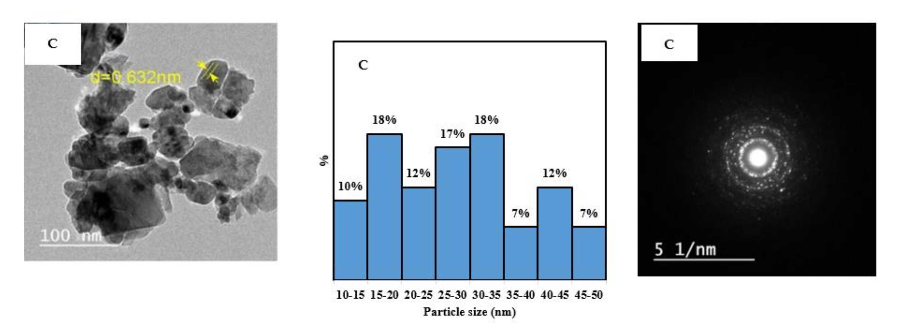
Figure 4 shows the TEM images of the five prepared samples. The concentric rings shown in the SAED images confirm the crystalline structure for all samples. The TEM images were used with image J software to find the particle size distribution for each nanocomposite.
Figure 4 shows that the nanocomposite Z has the narrowest particle size distribution, with 73% of the particles in the range of 5–10 nm. By increasing the percentage of the Cu precursor in the synthesis mixture, wider distribution and larger particle size were obtained. For 1C3Z, 1C1Z, and 3C1Z, 40%, 43%, and 40% of the particles, respectively, are in the range of 10–15 nm. For sample C, the particle size distribution is very widely distributed in the range of 0–50 nm, with most of the particles between 15–35 nm.
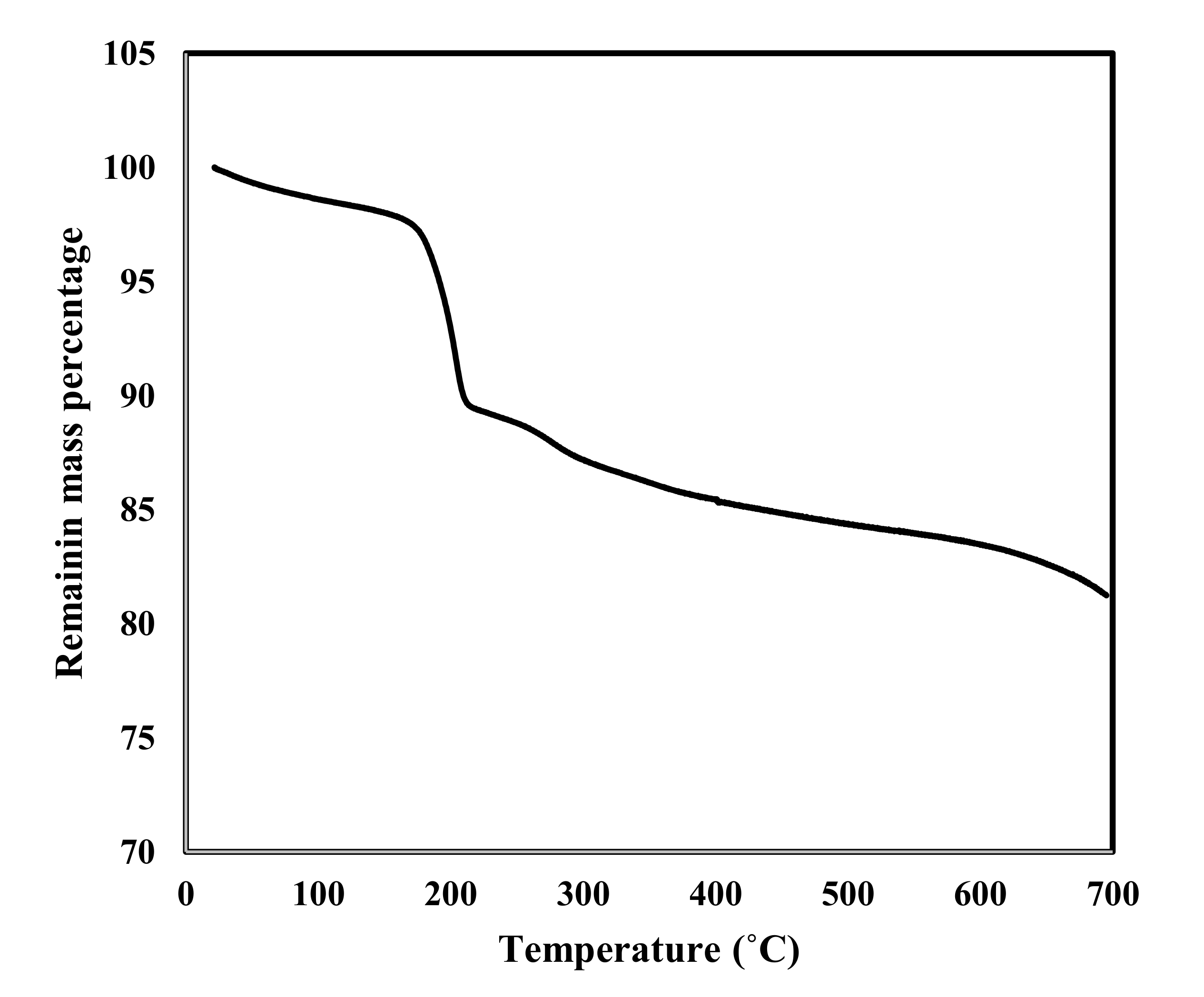
TGA analysis was performed for sample 1C1Z for the temperature range of 20–700 °C, as shown in
Figure 5. The sample lost only 2.5% during the first period of treatment (20–175 °C), which is mainly related to the loss of some adsorbed gases (CO
2, N
2) and water on the external surface of the sample. After that, the sample lost 7% before reaching 220 °C, which may be related to the strongly adsorbed water within the pores. After that sharp decrease in mass, the sample continued to lose mass in a slower and almost regular manner, until it reached a total loss of 18% at 700 °C. The last loss of material, almost 9%, may be related to the decomposition of some organic residual from the extract. This is supported by the EDEX analysis performed for the same sample (
Figure 6), which shows the presence of some minerals (Na, K) and Cl ions. These ions are mainly from the plant extract used during the synthesis process.
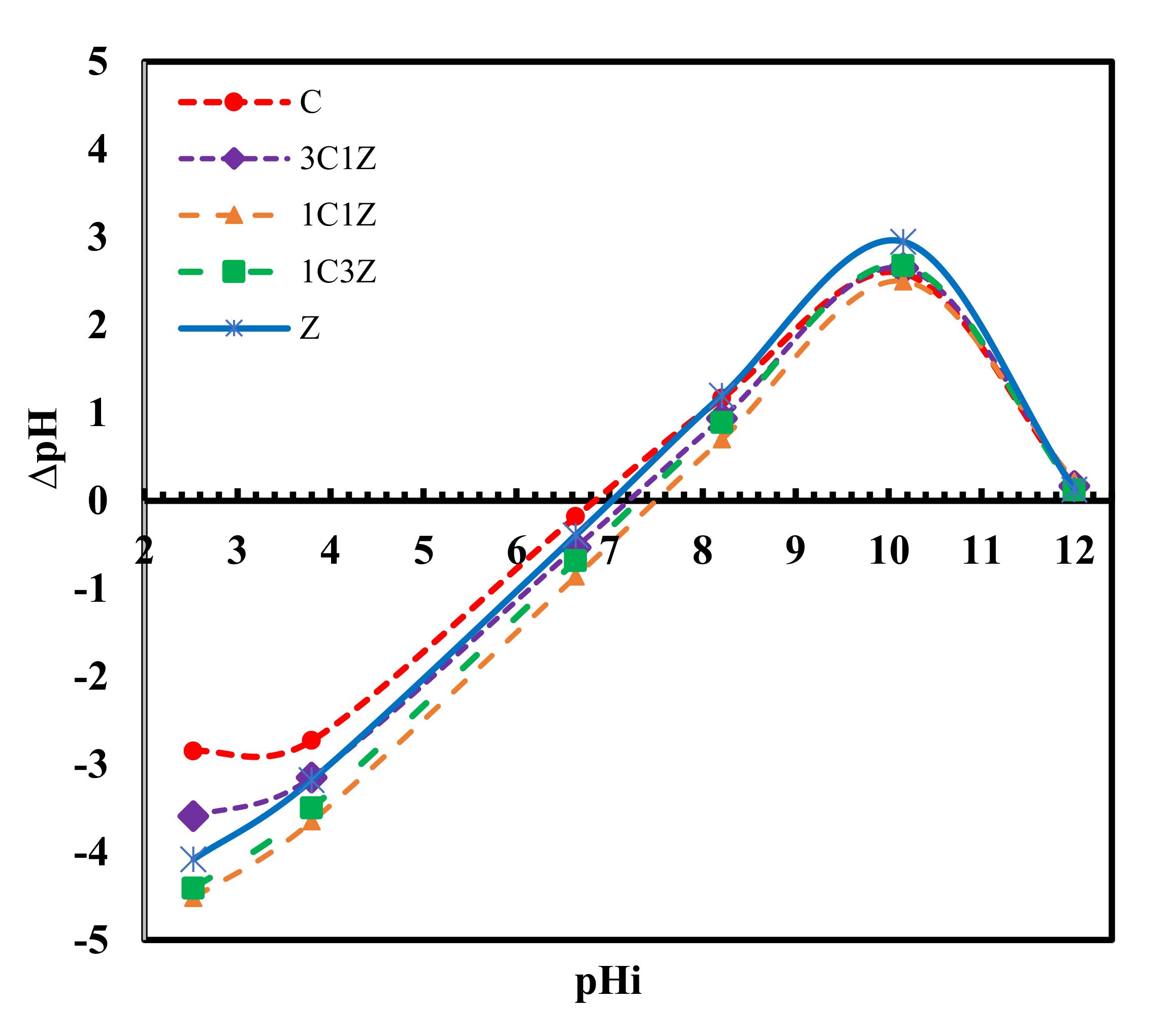
Figure 7 shows the results of the equilibrium technique used to measure the pH of the zero point charge for each sample. This point represents the x-intercept of the ∆pH versus pHi. From the figure, it is apparent that the pH
ZPC of Z, 1C3Z, 1C1Z, 3C1Z, and 1C are 7.0, 7.3, 7.5, 7.2, and 6.8, respectively. These values imply that, for a solution with a pH of higher than 7.2, all the samples are expected to be deprotonated and their surfaces will become negatively charged. On the contrary, if these samples are placed in a solution with a pH of less than 6.8, they will be protonated with a positively charged surface. This concept is very important for any surface phenomena such as adsorption or heterogeneous catalytic reactions, since the first step is expected to be the diffusion of the target molecule, which is MO, to reach the active sites on the catalyst surface; since MO dye is known to be an anionic dye that forms anions in aqueous solution, it is expected that decreasing the pH of the solution to a lower value than the pH
ZPC would enhance the degradation process by increasing the rate of reaching MO to the surface under the effect of electrical attraction. Accordingly, all the degradation tests were performed at a pH of 4.5, as will be discussed next. It is expected that under this pH value (4.5), the most positively charged surface will be 1C1Z, and this is maybe one reason for the best degradation efficiency obtained by this nanocomposite, compared to the other samples. Degradation results shown in
Figure 8 and
Figure 9 suggest that the main two parameters affecting the degradation efficiency of the prepared samples are pH
ZPC and the content of CuO. For samples Z, 1C3Z, and 1C1Z, there was a gradual increase in the degradation efficiency as a result of increasing both the CuO% and pH
ZPC. For samples 3C1Z and C, the degradation efficiency started to decline despite the increase in the CuO%. This may be related to the decrease in the pH
0 for these two samples.
Figure 10 shows that for the five nanocomposites, gas bubbles appear after adding the nanocomposite to the MO solution, which indicates the formation of CO
2 gas as a result of MO degradation, as reported by other research groups [
22,
23]. As the time passed, the number of gas bubbles decreased, as shown in the third row of
Figure 10, indicating that the rate of reaction slowed over time. This is mainly because the concentration of MO declines over time as a result of degradation; accordingly, the driving force for the diffusion of MO from the bulk of the solution to the surface of the catalyst becomes smaller, especially as the tests were performed stagnantly without any stirring, leading to a smaller amount of MO adsorbed on the surface of the catalyst and, thus, a slower rate of degradation.
Figure 10 also shows the change in solution color as a result of degradation.
To confirm the rule of the nanocomposite in the degradation process, a blank test (B) was performed by mixing the MO solution with H
2O
2 and adjusting the pH at 4.5. As shown in the first column of
Figure 10, there was no change in the solution color after 3 h or 24 h, indicating that no degradation took place. Another test was performed to confirm that catalytic degradation took place, rather than adsorption. This test was performed by mixing the MO solution with the nanocomposites without adding H
2O
2, and the pH was adjusted at 4.5. The obtained results showed no decrease in the concentration of MO.
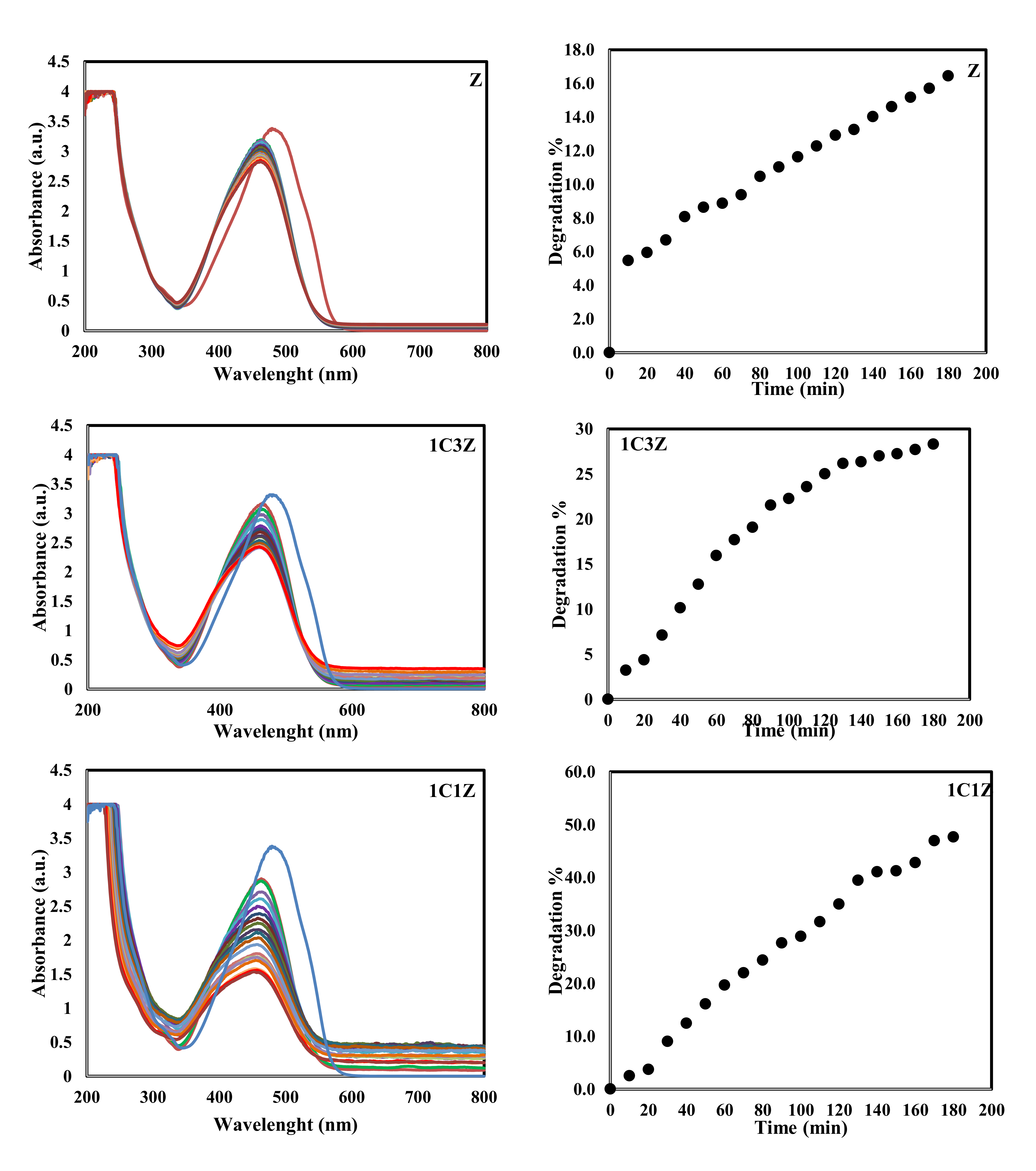
Figure 8 confirms the same thing through the absorbance of UV at different intervals (the highest spectra of each figure represents the absorbance at time zero, before adding the catalyst, and each lower one represents the absorbance after 10 min, until the end of the experiment). There is no change in the absorbance even after 24 h. Another experiment was performed using 1C1Z nanocomposite without controlling the pH at 4.5, as shown in
Figure 10, column 2. In this experiment, there was also no change in the color of the solution or the UV absorbance, as shown in
Figure 8, indicating that there was also no degradation in this experiment. This is mainly because MO is an ionic dye, which forms anions in an aqueous solution. When the pH of the solution (around 7.5) is higher than the zero point charge of the nanocomposite, the surface of the nanocomposite will gain a negative charge. Under this condition, a repulsive force between the anionic MO and the nanocomposite will prevent the MO molecules from reaching the active sites on the nanocomposite surface; thus, no degradation will take place. On the contrary, when the pH of the solution is lower than the zero point charge of the nanocomposite, the surface will gain a positive charge, which will attract the negatively charged MO, leading to a higher concentration of MO on the surface and, accordingly, a higher degradation rate.
Figure 8 and
Figure 9 show that the performance of the five samples toward degradation of MO follows the order C > 1C1Z > 1C3Z > 3C1Z > Z. For all the samples except C, there is a relation between the pH
ZPC and the degradation %. The higher the pH
ZPC is, the more the surface will be protonated and positively charged under the same pH condition, leading to a higher degradation performance. For sample C, one possible reason for the deviation is the larger and wider particle size distribution, compared to the other samples, which leads to a lower surface area and, accordingly, a lower number of active sites available for catalytic activity.


