1. Introduction and State of the Art
Over the last three centuries, manufacturing has radically evolved through the industrial revolutions. The manufacturing has moved from hand production to high automated production through the replacement of humans by machines. During the last decade, the technological advances have boosted the fourth industrial revolution (
Industry 4.0) [
1,
2]. Internet of Things (IoT), cloud computing, big data, robotics and Artificial Intelligence (AI) are the main involved technologies in the Industry 4.0 that aims at developing smart manufacturing for mass production by the provision of Cyber-Physical Production Systems (CPPS) [
3,
4]. Industry 4.0 is only focusing on the efficiency of the process ignoring the human role and capability that are crucial for a lot of production processes [
5], especially in the context of the new mass customisation trend. To respond to the multiple types of market demands, the manufacturing requires production lines to be adaptive, intelligent, and flexible for rapidly changing production methods and products. In such a context, the role of machines and humans has changed and evolved again.
Nowadays, we are living a new transition from the fourth to the fifth industrial revolution (Industry 5.0) [
6,
7]. As defined by the Directorate-General for Research and Innovation (European Commission) [
8] “
Industry 5.0 recognises the power of industry to achieve societal goals beyond jobs and growth to become a resilient provider of prosperity, by making production respect the boundaries of our planet and placing the well-being of the industry worker at the centre of the production process.”. Industry 5.0 is based on three pillars: Resilience—robustness in industrial production also in times of crisis; Sustainability—low energy consumption and greenhouse emissions by using and recycling natural resources; Human-centric—human is the centre of production process. The human-centric pillar is mainly based on Human-Robot Collaboration (HRC), human and collaborative robot (cobot) work together sharing tasks and spaces without separation fences [
9]. The absence of physical separation is the main issue for safely HRC application, especially for mobile robots and automated mobile cobots (AMCs) that can potentially navigate all around the factory.
There are a lot of safety standards and technical specifications for industrial robotics but almost all of them are not focused on the safety collaboration between human and robot. ISO 10218-1/2:2011 [
10,
11] and ISO/TS 15066:2016 [
12] define four basic levels of collaboration related to fixed cobot; moreover, ISO/TS 15066:2016 provides thresholds for human-robot contact related to the “quasi-static” and the “transient” contact. ISO 3691-4:2020 [
13] defines safety requirements for driverless industrial trucks, i.e., Automated Guided Vehicles (AGVs) and Autonomous Mobile Robots (AMRs). That regulation framework can no longer be applied for all the collaborations between humans and mobile manipulators, i.e., Autonomous Mobile Manipulator (AMM) as well as Autonomous Mobile Cobot (AMC), since the current standards do not address the new risks related to the integration of the two systems (i.e., mobile robot and manipulator).
The full HRC implementation requires new Standards and new approaches for both cobot and workplace design [
14] by using dedicated methods to assess application impact and safety [
15].
Industry 5.0 is taking factory to the synergistic coexistence of classic and HRC workplaces as well as AMM and AMC. The factory is an open space with humans and automated systems freely moving before, during, and after task execution. A complete definition of a such system, starting from its requirements up to its behaviour, requires the usage of multiple and heterogeneous models to catch all involved aspects as, for example, performances, safety, data monitoring, and requirement traceability during the life-cycle. In such complex scenario, characterised by the coexistence of heterogeneous data, new tools and methods are needed to support the definition of all requirements and their traceability during the design phase as well as the verification and validation of the designed solutions in order to correctly and completely assess the safety which enables the full HRC implementation. Moreover, the obtained results should be continuously updated according to the fault and unexpected events that occur during collaborative assembly operations. This implies the in-line process monitoring and the data exchange between physical system and digital models; their integration is the way to predict fault events and perform corrective actions for guarantying high level of safety for HRC applications. To reach and maintain a high safety level, tools and approaches are needed for supporting: (i) the modelling of complex and safety-critical system during all the life cycle phases; (ii) the integration of the different models of the system; (iii) the integration between the physical and digital systems (Digital Twin).
The present paper proposes a model-based approach to integrate performance and safety modelling for a collaborative workplace design. Moreover, the paper introduces a meta-model and a related instance to enable the Digital Twin integration.
1.1. Model-Based Systems Engineering
Model-Based Systems Engineering (MBSE) is the formalized application of modeling to support complex system requirements, design, analysis, verification and validation, beginning in the conceptual design phase and continuing throughout the development, and covering all life cycle phases [
16]. Models basically represent an effective way to support all the main steps of a System Engineering (SE) process for complex system development, usually represented as a “V-Model”. There are many different variations of the “V-Model” in the literature [
17], but the basic philosophy of the SE approach involves the following main, often iterative, steps: the descending branch includes the (i) requirements definition (ii) system decomposition and (iii) model implementation; while the ascending branch comprises the activities of (i) integration (ii) verification and (iii) validation of components, subsystems, and the whole system. The SysML-based methodology presented in [
18] helps to carry out the descending branch of the V-Model. It consists of two phases: (i) a Black Box Analysis (BBA) that provides a comprehensive and consistent set of functional and non-functional requirements by analyzing the system from an external point of view, and (ii) a White Box Analysis (WBA) that progressively leads to the internal architecture and behavior of the system. BBA and WBA use SysML diagrams to describe different viewpoints of the system. SysML [
19] is a unified general-purpose modeling language for high-level descriptive models; it also supports traceability among the different viewpoint diagrams.
In addition to designing the system to respond to the functional requirements, it is important to make sure that failures and dysfunctions among the system does not cause a big harm. To this end, Safety analysis and particularly Model-Based Safety Analysis (MBSA) must make part of the whole design process. MBSA requires the use formal languages such as AltaRica [
20,
21] in order to model and simulate the system behavior in different conditions in order to assess that the system satisfies the safety requirements.
Generally, model-based approaches deal with the same system providing different models according to the design viewpoint. Different models means different data often developed by using different languages and software. The development of a unified system model or linked models to obtain consistent system models is still a challenge.
Some researchers have dealt with the consistency of models through different approaches. For instance, the authors in [
22] proposed an approach named SafeSysE which proposes both a methodological approach that specifies the sequence of exchange between system and dependability analyses and also allows the generation of (partially filled) safety-related artifacts from system models to ensure their consistency. Nguyen et al. [
23] dealt with MBSE and MBSA integration through model transformation from SysML semi-formal models into AltaRica 3.0 formal language elements taking into account the system behaviour by using state machine elements. Berriche et al. in [
24] dealt with model synchronization through the abstraction of the different models into a common formalism and then their comparison and synchronization if inconsistencies are detected. Although some researchers have worked on the connection of different virtual models, no one provides a useful generalized method to link models.
1.2. Digital Twin
In recent years, the concepts of “cyber-physical systems” (CPS) and the “Internet of Things” (IoT) have emerged, both of which have a similar but different impact on the design, development and implementation of mechatronic components and systems, as well as on more complex systems resulting from the combination and integration of these [
25]. In the case of cyber-physical systems, individual components, often but not always mechatronic in nature, are combined and integrated through the use of advanced intelligent software. The Internet of Things represents a domain that is extended by access to and exchange of information to integrate both mechatronic and cyber-physical systems to create novel systems that are user-centric [
26,
27]. Starting with mechatronics, this section considers the design issues involved and discusses the product development process using model-based approaches. In this context, an important requirement is the interaction between systems at different hierarchical levels. This concerns modelling as well as simulation. The concept of a “digital twin” dates back to NASA’s Apollo program, where at least two identical spacecraft were built, allowing engineers to mirror the conditions of the spacecraft during the mission, with the vehicle remaining on Earth referred to as the twin [
26]. Nowadays, a digital twin refers to a computerized model of a product that is used for different purposes or product life phases. Currently, there are many definitions and explanations of the term “digital twin” in the literature. Depending on the information flow between the physical and digital object, a distinction is made between a “digital master”, a “digital shadow” and a “digital twin” [
28]. The problem is that a digital twin follows certain laws and properties in every application, but ultimately is different in every implementation. The research goal is to develop a generic meta-model [
29,
30] that can then be instantiated by the development engineer according to the respective circumstances. This leads to the question of what the structure of the meta-model should look like as a generic template, how can a digital twin for a collaborative workplace be specified from it?
1.3. Contribution
Through the designing workflow of a collaborative workplace for the assembling of an avionics Electro-Mechanical Actuator (EMA), the paper illustrates an operational flow to integrate MBSE, MBSA and multi-physics modelling activities; then it introduces a proposal for the Digital-Twin (DT) creation in order to integrate additional “digital services”, as for example, the support to system construction or commissioning as well as the control of maintenance activities, within the development process of the collaborative workplace.
The paper is organized as follows.
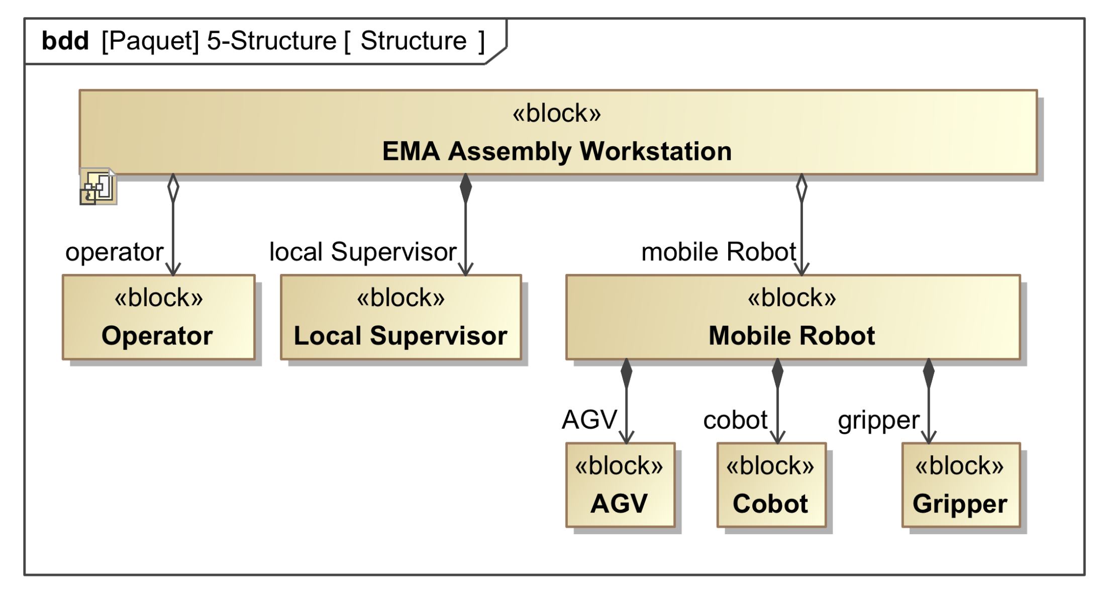
Section 2 describes the EMA collaborative assembly workplace. The EMA assembly workplace architecture, is presented in
Section 4. The safety model created with AltaRica 3.0 and the multi-physics model of the human-robot contact are presented in
Section 4.1 and
Section 4.2 respectively. Finally,
Section 5 proposes the meta-model for DT integration.
2. Ema Assembly Workplace and Scenario Description
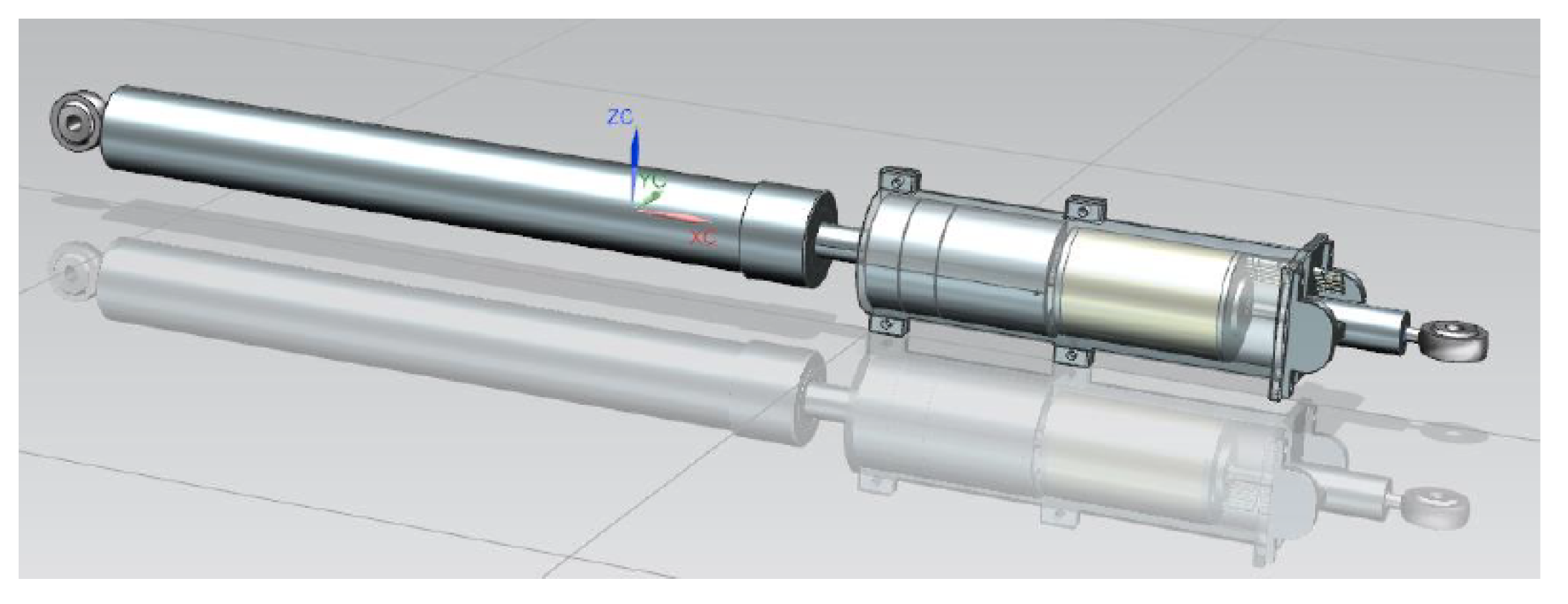
The case study in this paper is a collaborative workplace for the assembly of Electro-Mechanical Actuators (EMA) on aircraft wings. A human operator and a collaborative mobile robot (also named light hybrid cobot), assembly of an AGV (Automated Guided Vehicle) and a cobotic arm, have to perform a synergistic mounting operation with fitting (orientation and position), screwing and wiring of mechatronic components on a small aircraft wing on the aircraft assembly line.
In order to fit 2 EMAs on one wing of the aircraft on the production line, the robot carries, provides and handles the EMAs in turn (in a row) during a unique operation, thus allowing a dedicated operator to deal with wires and screws for the mounting of the mechatronic components on the wing and aileron assembly. This implies some long robotic displacements with high positioning and orientation accuracy, and a long holding in place time during manual operations.
Figure 1 shows the EMA and
Figure 2 shows the upper and lower positions of the aileron when the integrated EMA is at its longer and shorter extensions respectively. Finally,
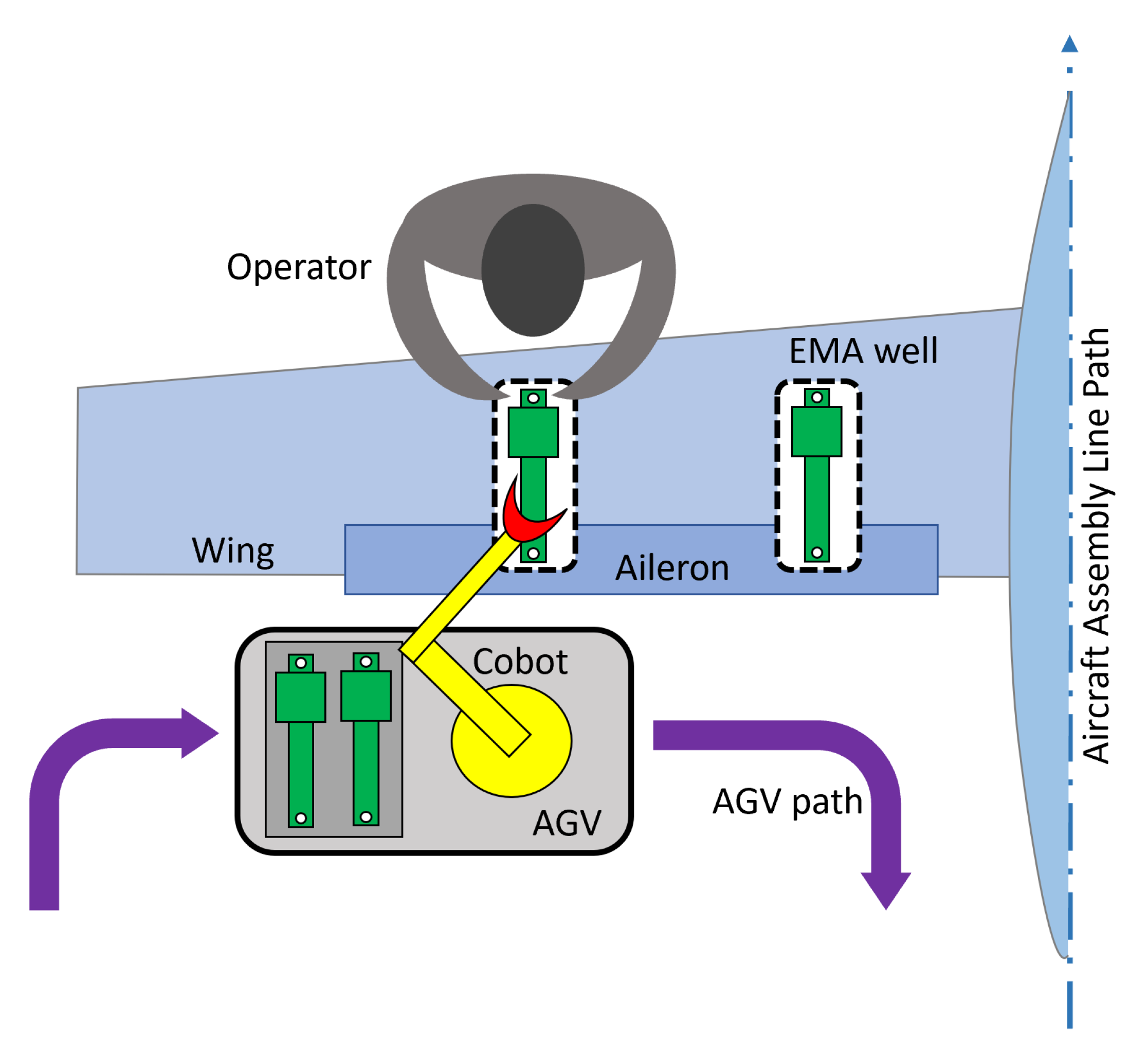
Figure 3 shows the upper view of the collaborative workplace with the wing, the AGV with associated cobot, and the operator.
Table 1 summarizes the main information related to the workplace, the EMA and the process to be considered.
Human-Cobot Collaboration Specification
The operation is performed by two main resources: a human operator and a mobile manipulator. A mobile manipulator can be defined as the combination of a robotic arm and a mobile platform (an AGV in the current use case). This complex scenario involves the interaction between a human operator and a complex machine which is able to move following a specific path performing material handling tasks. The main issue in this context is related to the safety of human operators during the execution of the multiple tasks. ISO 10218-1/2:2011 and ISO/TS 15066:2016 define four basic levels of collaborative operation: (i) Safety-rated monitored stop (SRMS); (ii) Hand guiding (HG); (iii) Speed and separation monitoring (SSM); (iv) Power and force limiting (PFL). The first above-mentioned three types consist in a low level of collaboration: human and robot simply coexist without sharing the same workspace or they share the same space but never at the same time. To be precise, the HG operations allow the space sharing between human and robot; however, the robot moves only through direct guiding of the human operator. The PFL level is the most complex level of collaboration. It allows to achieve a real collaboration between human and robot, but since it is a “hand-in-hand” collaboration it takes into account the possibility that unwanted, unpredictable contacts may occur. The application described in this manuscript can be classified as PFL application, even if it should be taken into account the further complication due to the movement of the mobile manipulators. However, the technical specification ISO/TS 15066:2016 introduces the “quasi-static” and the “transient” contact. The former could involve the clamping of the operator’s body part between a moving part of the robot and another fixed part of the workplace (e.g., operator’s hand clamped between the robot arm and the aircraft wing or the EMA); it could be a sustained/prolonged contact. The latter could be a more “dynamic impact” like a collision between a moving part of the robot and a human body part. The actual contact characterized by short duration. Then, the ISO standard provides some reference tables of the permissible threshold values for bio-mechanical loading according to the exposed body region of the human operator. Maximum force and maximum pressure values are provided for quasi-static contacts; peak force and peak pressure values can be at most twice as great as quasi-static values. Contact with face, skull and forehead is not permissible. These values must be respected by the design and verified through the simulation of multi-physics models as will be presented in the next sections.
4. System Architecture Evaluation
The White-box analysis provides one or more candidate architectures that must be evaluated with regards to the requirements (including performance and safety requirements as well as other constraints such as the cost). In this case we have defined one architecture and we will check both safety and performance requirements. For this purpose, first safety analysis is given in
Section 4.1. Then, multi-physics models (introduced in
Section 4.2) will be built with Modelica to assess the system behavior.
4.1. Safety Analysis
A preliminary risk identification was performed and helped in identifying the following undesired event “Undesired contact with operator hands” during the “Assembling EMA” phase where the cobot is close to the operator (c.f.
Figure 6). During Assembling EMA phase, the AGV, Cobot and Gripper shall stay motionless while holding the EMA in position so that the operator safely performs the integration tasks (connecting wires and screwing the EMA to the wing). To model this behavior, an AltaRica 3.0 [
20] model is built. In this model (c.f.
Figure 11), first a class of component is defined in which the component is initially motionless and an event “inadvertent” is defined that will make the component become mobile (motionless becomes false). The component also has an input “in_position” and an output “out_position”. Then, the global system is built by instantiating three components that are respectively the AGV, the Cobot and the Gripper. A stepwise simulation allows to play many scenarios with the system. For instance, in
Figure 12, we can see that if the AGV moves inadvertently, then the final observer corresponding to EMA_position becomes false. This means that the EMA hold by the cobot is not in the intended place which means that there is a risk for it to hit or pinch the operator expressed above by the undesired event “Undesired contact with operator hands”. By simulation of the AltaRica code or by generating the corresponding fault tree ( given in
Figure 13), this event can be caused by one of the following events (or failure modes):
The gripper moves inadvertently “Unintended proper motion of the Gripper”
The cobot moves inadvertently “Unintended proper motion of the Cobot”. This would lead to the moving the Gripper consequently.
The AGV moves inadvertently “Unintended motion of the AGV” that in turn would result in moving the Cobot and the Gripper.
The operator and AGV plus cobot are physically separated by the wing and aileron assembly. However, while displacing and EMA, the cobot may hit the operator. In the same way, while the cobot+gripper handle the EMA prior to connection (mechanical fixation data bus, electrical wiring), the hands of the operator are working in the EMA well area, meaning that his hands may be pinched between the robotic arm and the wing and aileron elements. Then, whatever the reason, if the cobot detects an obstacle during any displacement, it has to drastically reduce its force/torque and stop in order to analyze the situation before any restart.
Considering the proposed use case, unwanted contact is more likely to occur between the operator’s hands and the robotic arm as represented in the
Figure 14. It could occur a quasi-static contact or a transient contact. Referring to the tables provided by the Annex A of ISO/TS 15066:2016, it is possible to identify the maximum permissible pressure and force both in the first and in the second case (see
Table 2).
Furthermore, the maximum permissible energy transfer may be defined as a function of the maximum force or maximum pressure values as stated in Equation (
1):
Where
E is the transfer energy,
and
are respectively the maximum contact force and the maximum contact pressure for specific body area,
k is the effective spring constant for specific body region (these values is provided by the reference ISO standard), and
A is the area of contact between robot and body region. For the current case, considering “Hands and fingers” as body region, the ISO/TS 15066:2016 specifies a maximum transferred energy equal to 0.49 J for contact area of approximately 1 cm
2 (see
Table 3).
The energy transfer threshold value for the current contact scenario is used to identify the maximum speed at which the robot could move within the collaborative workspace according to the following equation:
For the assumption behind the calculation of these limit values, the reader could refer to the ISO/TS 15066:2016. We simply recall here that is the reduced mass of the two-body collision model described by the technical specification, whereas is the relative speed between the robot and the human body region.
In conclusion, the limit values of force, pressure and speed for the current contact scenario (i.e., contact between operator’s hands and the robotic arm) are set and reported in the
Table 4. The relative speed is limited to 1200 mm/s since this value brings the transfer energy to 0.42 J/cm
2 which is less than the limit value based on conservative estimates and scientific research on pain sensation [
12]. This computation takes into account the simplified mass distribution model that the technical specification provides, and considers an effective mass of 20 kg.
4.2. Mechatronic Design and Analyses (Modelica) for Nominal and Dysfunctional Behavior
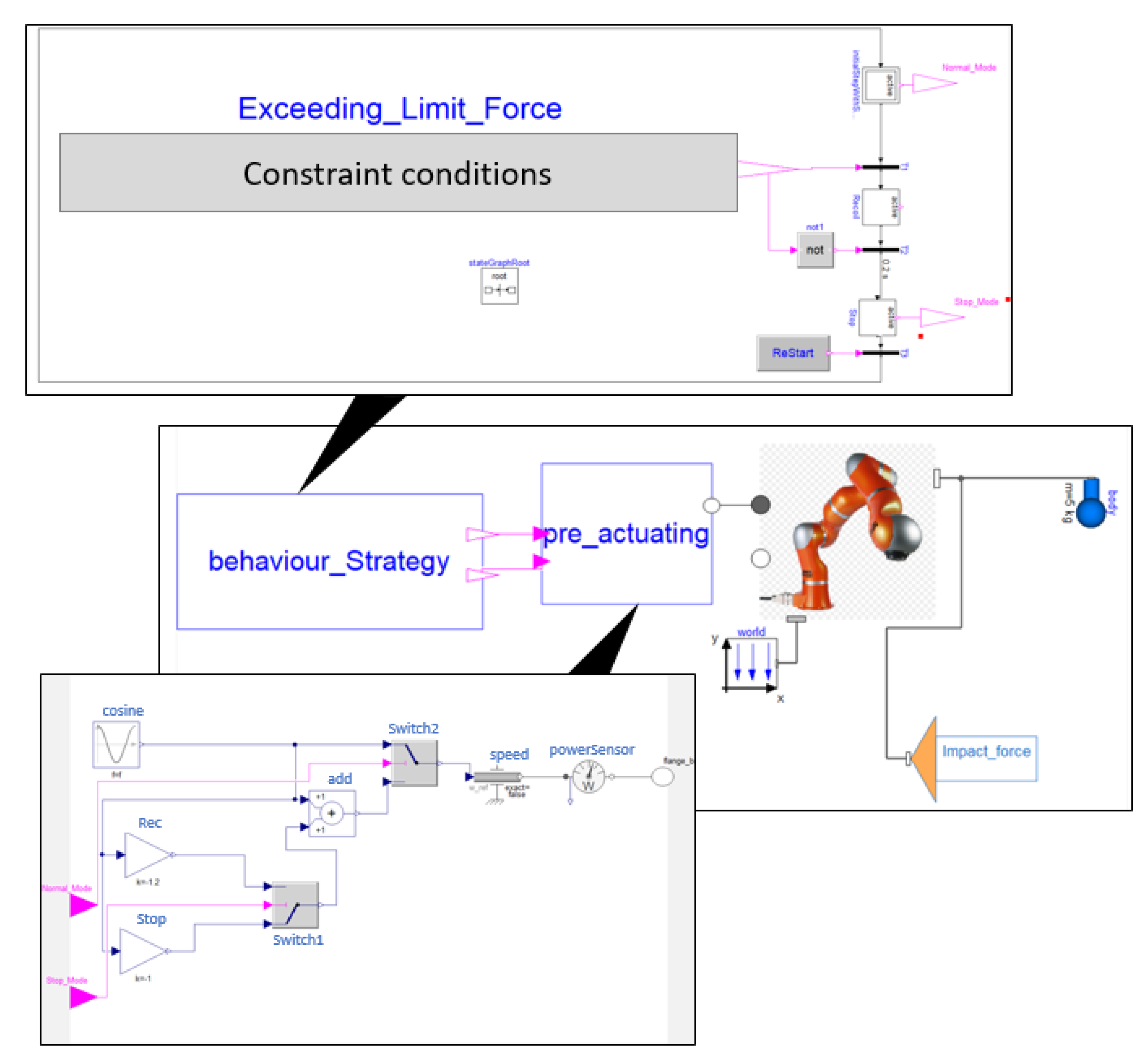
A multi-physics model is built with Dymola tool and Modelica language to ensure that the system does not exceed the permissible force thresholds specified by the ISO/TS 15066:2016 technical specification. Thus, a dedicated model is built in order to evaluate the control strategy to limit the force on the operator if the undesired contact with operator hands occurs. In our example, this limit is based on the maximum permissible force of 280N for a transient contact on hands and fingers. The same modeling and simulation approach can be used to deal with the maximum contact pressure, contact speed and transferred energy. This is illustrated with a Dymola modeling in
Figure 15.
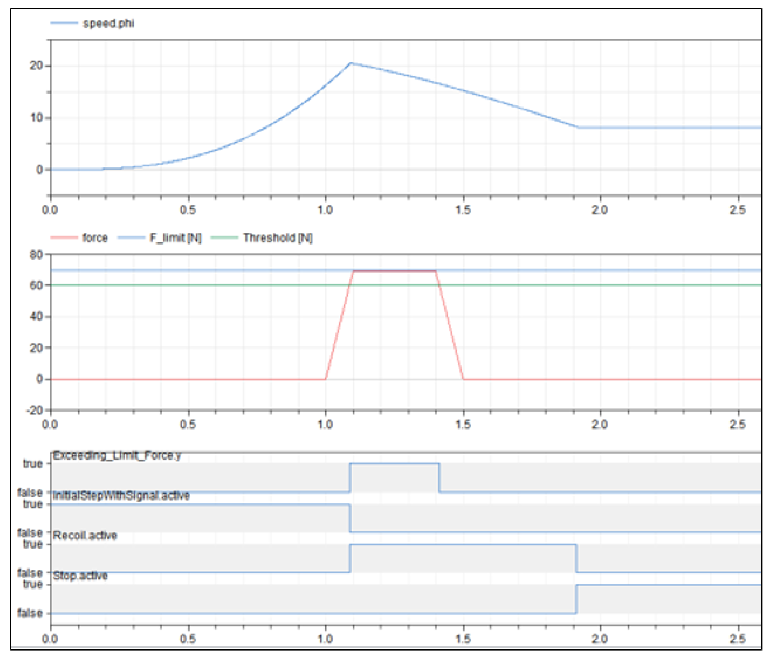
Figure 16 displays some results associated to a scenario of contact during the beginning of an undesired rotation of the main axis (base) of the cobot, the detection of this contact, the stopping of the dangerous movement followed by a backward rotation in order to protect the operator.
5. Meta-Model for Digital Twin Integration
This section deals with the integration of the previous models and analyses within a Digital Twin for the collaborative mechatronic design task. Digitization is advancing in many areas and is now loading most companies with additional work tasks. These are usually triggered by additional new requirements of customers who not only want to purchase the product, but also additional “digital services”, such as virtual models for integration/use in development in order to be able to make statements about the overall performance of a complete system or support for construction and commissioning (virtual commissioning) or additional tools for controlling maintenance activities, such as reliable statements about the remaining service life. All these aspects can be summarized under the umbrella term “digital twin” and now pose additional challenges, especially for the producers of mechatronic systems. On the one hand, a large number of virtual models (as, for example, geometry, design calculations, simulations, etc.) are usually available from the development phase, and on the other hand, a large number of data can be obtained from measurements during operation. However, this available database is not always uniform and consistent (e.g., different software tools, data formats, completeness, accuracy). Therefore, it is not always possible to create added value in a single step. The aim of this section is to provide insights on the way of creating a digital twin, on the basis of different initial conditions and models. In the context of this article, a definition based on [
28] is used: A digital twin is a virtual dynamic representation of a physical system, which is connected to it over the entire product life for a bidirectional data exchange.
Figure 17 shows the typical phases of a product’s life, focusing on the phases of development, production and use. In order to accomplish a virtual dynamic representation of a system a distinction has to be made between the physical, digital and cyber layers.
5.1. Approach for Integration
System-level models should at the very least be able to manage existing data and to illustrate both the relationships within a system (between its sub-systems) as well as those between a system and its environment. Additionally, they should make it possible to execute several simulations of test cases, thus allowing specific “global” system properties to be evaluated. In many cases it is neither feasible nor even possible to build a model of the overall system simply by combining or assembling a large number of sub-system-specific (more or less isolated) models without adapting them (model reduction, simplification), since the system-models resulting from such an approach easily become confusing, too complex, and unmanageable. The goal is now to create a meta-model that represents the information of the individual property-view that is relevant for other views. The challenge here is that the knowledge about the overall system is not equal to the sum of the knowledge from the corresponding sub-systems, since each sub-system is in principle self-contained and can therefore only respond to the needs of the other domain to a limited extent. The knowledge must therefore be generalized (abstracted) and integrated. The separate treatment of system models and property-specific models has the consequence that the information is distributed to different places and therefore the traceability of the model data is required in order to be able to trace design decisions and be able to make changes consistently.
Figure 18 presents the Meta-model for describing the interaction between systems and their related properties. On the right side the instance for the EMA assembly workplace is shown.
5.2. Specification of a Digital Twin for the Collaborative Workplace
With the objective of integrating MBSE and MBSA approaches together with multiphysics simulations as early as possible in the design process and all along the system life cycle, some relevant scientific barriers for a DT accomplishing a virtual dynamic representation of a real system are:
How to formally structure and consistently implement a unique digital twin to efficiently deal with a multi-criterion heterogeneity (context, modeling intention, languages, temporality, abstraction, breakdown and refinement levels, etc.) of system, safety and multiphysics models?;
What are the different digital interoperating contents of the digital twin, and how do they interoperate on a logical and consistent way?;
How to produce or reuse the different models (i.e., libraries with generic models to be customized and instantiated) in a coherent and compatible way to be co-simulated as close as possible to the reality, and ensure that after completion they can be proved to be equivalent to a physical reality?;
How to use system, safety and multiphysics Digital Twin to validate the system?
To deal with these scientific barriers, our proposal (give in
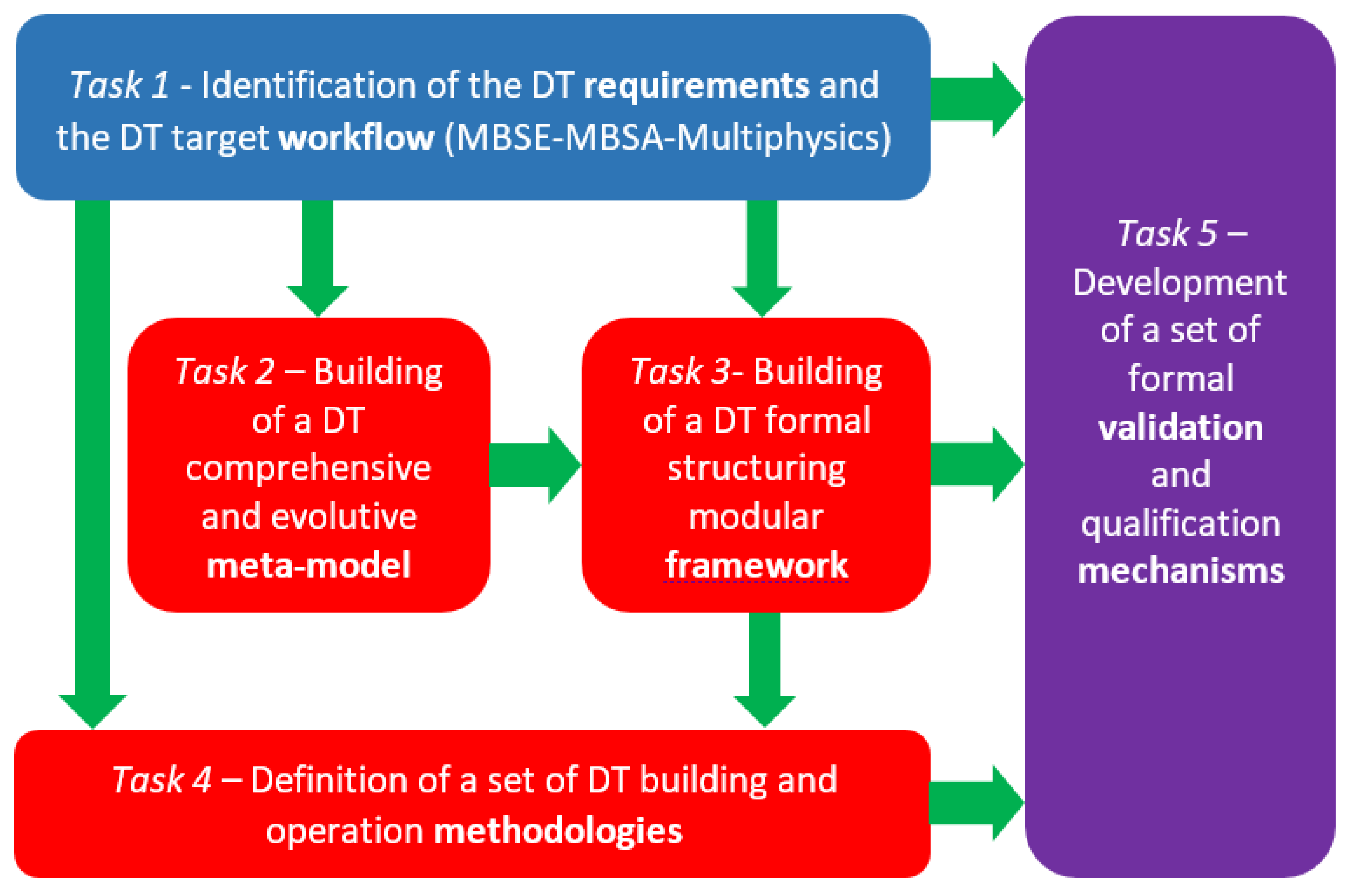
Figure 19) is that the main development tasks of a DT related to the collaborative workplace may consist in:
Identification of the DT requirements and the DT target workflow: from the previously defined system models and simulation workflows based on MBSE, MBSA and multiphysics analyses, identify the DT requirements and define a target workflow merging new or adapted system, safety and multi-physical models in a unique framework, in order to perform exploration, evaluation, comparison, selection and validation for candidate system architectures (e.g., the number of axis required on the cobot), new technologies (e.g., different kind of gripper, axis motors, sensors or controller) and new usages (e.g., new cobot reachable tasks).
Actions required:
- -
To analyze the need for coupling co-simulable systems models (e.g., with SysML), safety models (e.g., with AltaRica) and multi-physical models (e.g., with Dymola-Modelica);
- -
To perform the current design workflow (models, tools, languages, connectors, etc.) for the collaborative workplace and specify the target process that will be supported by a System-Safety-MultiPhysics Digital Twin;
- -
To identify potential consistency issues, impact links between models, coverage, equivalence: depending on the modeling contents with different languages, different points of view on the system are covered; these points of view may present some overlapping areas which must not be contradictory;
DT meta-model building: to build a comprehensive meta-model encompassing all necessary DT objects (different models and their modeling objects, simulation tools, real system data, etc.).
Actions required:
- -
To define a well-structured meta-model for a theoretical framework, supporting the target workflow for system, safety and multiphysics integration, ensuring modularity, consistency, inheritance and relational dependencies;
- -
To specify the Digital Twin context with its input/output (real system, designers, experts, operators, etc.);
- -
To identify the Digital Twin relevant elements (tools, models, data, information and knowledge, etc.);
- -
To address the Digital Twin internal workflow and processes, dealing with synchronization of tools, time(s) keeper, data/information/knowledge exchange, models and data consistency, traceability;
- -
To enlarge the initial set of DT requirements to include the specification of a formal framework able to support the implementation of the Digital Twin.
DT formal framework: to define a formal structuring modular framework in order to structure the DT, with all interfaces between models, tools and the real system.
Actions required:
- -
To propose a structuring formal framework based on mathematics (graphs theory, set theory, category theory, algebra, etc.) and relevant formal modeling languages (i.e., SysML V2, S2ML, etc.), to support the target workflow, the previously defined meta-model, and to formally declare all kinds of relevant elements of the digital twin, all kinds of relations between these elements, and the possible transformations of elements and relations, with compositionality properties for modularity and scalability;
Definition of DT methodologies: to define all necessary methodologies to build and to operate the Digital Twin on the basis of the proposed meta-model and formal framework. Thus, the objective is to define a two-fold methodology enabling to choose and elaborate models, build and operate a consistent digital twin satisfying the needs of system and multi-physics designers, and safety experts.
Actions required:
- -
To define a methodology to build the digital twin on the proposed foundations (meta-model, framework, target workflow) for a given system with relevant tools and bridges, languages and models, such as Dymola (Modelica), Cameo (SysML), OpenAltarica and 3D modelers;
- -
To define a methodology to operate the digital twin in order to perform functional and dysfunctional simulations regarding the target workflow;
Development of validation mechanisms: Thanks to the formal framework relying on mathematical principles, to elaborate some validation and qualification mechanisms to deal with the DT target workflow results and propose some corrections, adjustments or modifications on both the DT and the real system, in order to have them converge and improve.
Actions required:
- -
To define formal reasoning based on mathematics and logic;
- -
To propose methodologies to perform trials, for example for undesired events (safety, black swan sequences, etc.). In the case of the EMA workplace, undesired events may be numerous and the DT will offer the opportunity to play more dysfunctional scenarios than the usual design workflow actually can provide, as previously defined;
- -
To validate these results with real data or constructed data (e.g., provided by experience plans) related to industrial scenarios and current workflow, such as the presented mechatronic design of the EMA workplace.
6. Conclusions and Future Works
Coupling MBSE, MBSA and multiphysics models is difficult but of huge interest since a growing number of mechatronic systems are safety critical. Beyond models, tools and language to design such systems, relevant collaborative methodologies and resulting workflows are of strategic importance to fulfill the designing goals and proceed towards the human-centric pillar of Industry 5.0. We have shown the above mentioned coupling by considering a collaborative workplace for aircraft assembly (EMA assembly workplace). In order to deal with the complexity of the system itself and its associated collaborative design process, it is important to perform as many as possible functional and dysfunctional experiments with a DT connected to the physical system, in order to have both of them improved and converging. To this aim, we have addressed the need and the barriers for a DT and proposed an approach to accomplish the DT integration. A meta-model has been formulated and an example, related to the EMA assembly workplace has been introduced. A set of development tasks for the EMA assembly workplace has been proposed. Further activities will deal with the detailed implementation of the DT, by using the set of development tasks and the successive validation steps, in order to accomplish the needed level of exchanging data between the DT and the physical system.


 ,
, 


