Abstract
This paper proposes a new method of target localization and tracking. The method consists of four parts. The first part is to divide the scene into multiple cells based on the camera’s parameters and calibrate the position and error of each vertex. The second part mainly uses the bounding box detection algorithm, YOLOv4, based on deep learning to detect and recognize the scene image sequence and obtain the type, length, width, and position of the target to be tracked. The third part is to match each vertex of the cell in the image and the cell in the scene, generate a homography matrix, and then use the PnP model to calculate the precise world coordinates of the target in the image. In this process, a cell-based accuracy positioning method is proposed for the first time. The fourth part uses the proposed PTH model to convert the obtained world coordinates into P, T, and H values for the purpose of actively tracking and observing the target in the scene with a PTZ camera. The proposed method achieved precise target positioning and tracking in a 50 cm ∗ 250 cm horizontal channel and a vertical channel. The experimental results show that the method can accurately identify the target to be tracked in the scene, can actively track the moving target in the observation scene, and can obtain a clear image and accurate trajectory of the target. It is verified that the maximum positioning error of the proposed cell-based positioning method is 2.31 cm, and the average positioning error is 1.245 cm. The maximum error of the proposed tracking method based on the PTZ camera is 1.78 degrees, and the average error is 0.656 degrees.
1. Introduction
With the continuous advancement of science and technology and the continuous improvement of people’s living standards, video surveillance has played an increasingly important role in people’s lives [1,2,3,4]. The traditional monitoring method based on a fixed perspective can no longer meet people’s increasing demand for security protection. Therefore, PTZ cameras with rotation, pan, and zoom functions have gradually become a focus of people’s attention [5,6,7,8]. A camera with a PTZ function tracks and observes the target in the scene by changing its own parameters. However, due to the constantly changing position, speed, size, and background of the moving target in the scene, it is easy to cause a situation where the target cannot be accurately located, or the tracking target is lost. Recently, domestic and foreign researchers have conducted many related studies, but there are still many key issues to be urgently solved [9].
The PTZ camera has the function of real-time perception of the external characteristics of the target in the scene. However, if one wants to further perceive other target characteristics, such as type, location, and speed, a new observation model must be built.
To use the PTZ camera to obtain accurate target information such as type, position (speed), etc., we propose a target localization and tracking method based on cell and active cameras. In this method, we divide the area of target movement into multiple cells. We then use deep learning-based algorithms to identify the vertices and targets of the cells in the scene, and then use the PnP algorithm to calculate the world coordinates of the targets in the image. Finally, based on the target’s world coordinates, the PTH model is used to calculate the P and T values of the PTZ camera, in order to achieve the purpose of tracking and observing the target.
This experiment was conducted with a wireless remote-control Jeep (hereafter referred to as “WRC-Jeep”) as the target and it was compared with other target tracking methods. The main contributions of this article are summarized as follows:
(1) A cell segmentation and recognition method is proposed for the first time. This method divides the experimental scene into multiple cell areas, calibrates each cell’s vertices, and then uses the YOLOv4 detection algorithm to identify the vertices of the cells and the target in the image. Finally, the proposed vertex matching method is used to match the vertex in the image and vertex in the scene.
(2) A method for accurately calculating the target position is proposed first. Firstly, we used the PnP model to calculate the target’s initial position. Secondly, we used the proposed error model to calculate the target error position. Finally, we used the target position to subtract the error position to obtain the precise target position.
(3) A PTH model is constructed. The world coordinates can be transformed into P value, T value and H value based on the PTZ camera.
2. Related Work
2.1. Image-Level Target Tracking
Before 2010, researchers achieved fruitful results in the field of target tracking. Classic target tracking algorithms included Meanshift [10], Camshift [11], particle filter [12], and the Kalman filter algorithm, as well as the optical flow algorithm, and so on. However, these classic target tracking algorithms also have some problems, including limitations in feature representation. When the target is deformed, partially occluded, and there is similar target interference in the background, it will cause the tracking target to be lost, or cause a large error in the target trajectory.
The Siamese network trackers and correlation filter trackers have better performance, with the appearance of many new target tracking algorithms. Compared with the traditional correlation filtering algorithm, when the SiamFC algorithm [13] is used to track the targets, the targets in the first frame are used as the templates for subsequent frame tracking, and the templates will not change. This also causes the tracking template not to change with the change of the target. The disadvantage is that it cannot perceive the change of the target. When the parameters of the target change, the tracked target is likely to be lost. Classical Siamese network tracking algorithms include SiamFC [13], SiamRPN [14], SiamRPN++ [15], etc.
The essence of the correlation filtering algorithm and its improved algorithm [16,17,18,19,20,21] is to find an area with the greatest correlation with the template in the current frame of the video sequence. The tracking template comes from a filter of online learning. In tracking the target, the correlation filtering algorithm continuously updates the template. The performance of the updated template directly determines the effect of target tracking. The classic correlation filtering algorithms include MOSSE [22], CSK [23], KCF [24], DSST [25], SAMF [26], SRDCF [27], Staple [28], C-COT [29], ECO [30], and ATOM [31].
Many excellent deep learning-based target tracking algorithms have emerged. They are divided into two categories. One is based on region proposals, and the main representatives are R-CNN, SPP-net, Fast R-CNN, Faster R-CNN, R-FCN, etc. The others are based on the end-to-end algorithm, mainly represented by SSD [32] and the YOLO algorithm [33,34,35,36].
2.2. Device-Level (PTZ Camera) Target Tracking
Hu et al.’s [37] method uses two PTZ cameras to observe moving targets in the path, such as alternate channels. The experimental scene is divided into several continuous cells, and then each cell is calibrated. The PTZ camera quickly calibrates online after the operation and then tracks the moving targets in the cell for observation.
In Nacer Farajzadeh et al.’s method [38], the area of interest is first manually selected, and then the three features of the feature points in the area are extracted. The features include the mean, the variance, and the range of intensity values. Then, they calculate the transformation matrix with the information of the feature points and the K-means algorithm for the purpose of tracking the target of interest in the image.
Liu et al. [39] proposed a target tracking model based on a PTZ camera. The model consists of background modeling, observation frame registration, and target tracking. The first step is to build a background model for the observation scene. Then, the feature extraction algorithm is used to register the region of interest in the adjacent frames; finally, the classic target tracking algorithm is used to cooperate with the PTZ camera to achieve the purpose of actively tracking the target in the scene. This method makes full use of the advantages of the PTZ camera and combines the image-level target tracking algorithm to realize the tracking of the scene target.
Kang et al. [40] built a moving target tracking system based on a PTZ camera. The system includes three parts: adaptive background generation, moving region extraction and tracking. Similar to the method proposed by Liu et al., it also needs to build a background model of the scene first, and then extract the moving target from the continuous frame. Finally, we changed the PTZ parameters of the active camera for the tracking target.
Lisanti et al. [41] proposed an online calibration method for a PTZ camera. First, the internal and external parameters of the camera were calibrated offline before the operation. Then, when the PTZ camera started working, the shooting attitude of the current camera was calculated by extracting the captured image features, and then it was compared with the external parameters of the calibrated camera. Following these steps, the camera’s attitude was adjusted to track and observe the target.
Shakeri et al. [42] used a dual-camera system to locate and track small targets in the scene. This method constructs a camera model that extracts the target features to calculate the best posture. We adjusted the parameters of the PTZ camera to track and observe the target.
Baris et al. [43] constructed a dual-camera system for target tracking and observation. The dual-camera system includes an omnidirectional camera and a PTZ camera. First, the omnidirectional camera provides a 360-degree field of view to locate and classify the target. Then, the PTZ camera is used to track the target.
Hu et al. [44] constructed a PTZ camera observation model, namely a four-cell-based image target tracking method. They achieved image target tracking by one PTZ camera. However, the method cannot precisely locate the target and has a significant tracking error.
3. Methodology
The proposed method mainly includes four parts. Firstly, the scene is divided into multiple cells that were calibrated; secondly, YOLOv4 is used to detect the image coordinates of the target and the cells’ vertices. Then, the cells’ vertices in the image are matched by the proposed matching method; thirdly, the precise world coordinates of the target are calculated by the proposed method; finally, the world coordinates are transformed into angles of the PTZ camera, to track and observe the target. The overall flow chart of the system is shown in Figure 1. The specific method is to change the P value and T value of the PTZ camera continuously to ensure that the moving target is always in the center of the FOV (field of view).
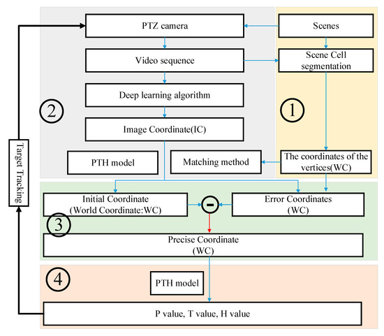
Figure 1.
The overall flow chart of the proposed method.
3.1. Cell Division and Vertex Calibration in the Experimental Scene
In a wide traffic scene, it is often impossible to observe the dynamics of the entire scene through a fixed-view camera. In contrast, a PTZ camera obtains information about targets in a wider scene by adjusting the camera’s observation parameters. Furthermore, observing the target in real time with an active camera is an effective method for obtaining the target’s motion information state. The purpose of this paper is to propose an approach based on the scene’s cell division for precisely positioning the target and tracking and observing it in real time using the active camera. As shown in Figure 2, suppose the camera is on the ZOY plane in the world coordinate system, and the target is on the XOY plane. The target area is partitioned into continuous cell areas using predefined rules, and each cell area’s vertices are calibrated.
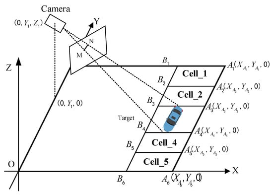
Figure 2.
Cell-based scene segmentation.
3.2. Target Localization on an Image
This research employs YOLOv4 to complete the detection and recognition of ship targets in the image. Alexey Bochkovskiy’s team proposed YOLOv4 in 2020. This algorithm is based on the YOLO series [34,35,36,37] and can accurately and rapidly detect and identify targets in images. On the Tesla V100, the YOLOv4 algorithm detects objects in real time at a rate of 65 fps and with an accuracy of 43.5% AP.
The prediction method of the YOLO series algorithm is shown in Figure 3. The recognition result of YOLOv4 is shown in Figure 4. The neural network predicts five bounding boxes on each unit of the feature map, and each bounding box indicates five values, which are . The first four values are coordinates and is the confidence level. The length and width of the bounding box corresponding to the cell are , respectively. The distance between the cell and the upper left corner of the image is . Then, the predicted value is
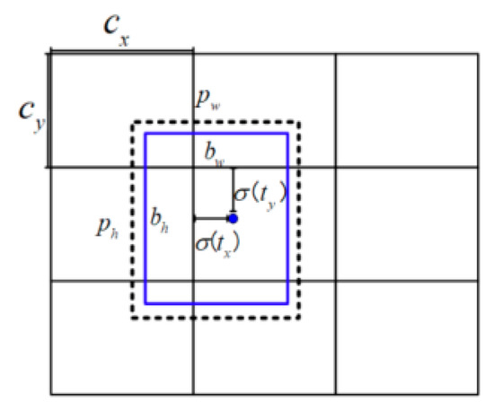
Figure 3.
Bounding box prediction of the target.
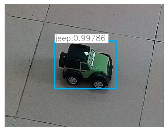
Figure 4.
Target detection with YOLOv4.
In the text, (Target: ) is used to represent the target in the image; “Jeep” and “cross” are the target types; and are the coordinates of the center point of the target bounding box.
We detected the coordinates of the target in the image and the coordinates of all cell vertices with the YOLOv4 algorithm, and then compared the pixel distances from the image’s principal point to all vertices in the image. The distance formula is:
We picked out the four vertices closest to the center of the image and considered these four vertices to be the four vertices of a cell. The world coordinates of the principal point of the image in the scene can be calculated with the PTH model. Because the world coordinates of the vertices of each cell are manually calibrated when the scene cell is divided, it is easy to calculate in which scene cell the principal point of the image is located. Finally, the proposed matching method matches the vertices of the image cell with the vertices of the scene cell. For different channels (horizontal or vertical), different matching methods are adopted.
For the horizontal channel, the method used mainly includes two steps. First, we calculated the distance between the vertices of the cell and the vertex of the lower left corner of the image to identify the vertices A1 and A3. Then, we calculated the abscissa of the remaining two vertices. The vertices A2 and A4 can be identified as well. The specific identification method is shown in Figure 5.
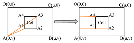
Figure 5.
Recognition method of the cell vertex in the horizontal channel.
For the vertical channel, the method adopted is shown in Figure 6:
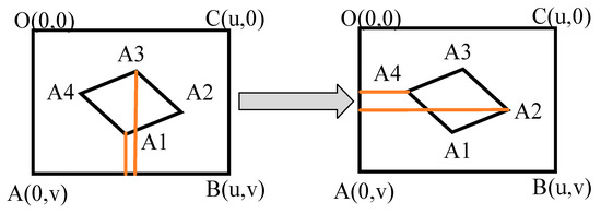
Figure 6.
Recognition method of the apex of the vertical channel.
When the principal point of the camera is at the starting point, it can be directly determined that the target is in the first cell After the camera moves for the first time, the cell recognition method shown in Figure 6 can be adopted. Figure 6 shows the method to distinguish the cell’s vertices in the vertical channel. Under different shooting angles, the attitude of the cell is different, but its direction is generally as shown in Figure 6. The abscissa value of vertex A2 is the largest, the abscissa value of vertex A4 is the smallest, the ordinate of vertex A1 is the largest, and the ordinate of vertex A3 is the smallest. The four vertices can be distinguished in this way.
3.3. From Image Coordinates to World Coordinates
We set the plane where the target object is located as the XOY plane of the world coordinate system and set the z-axis as the straight line passing through point O and perpendicular to the XOY plane. MN is the image of the target in the camera, as shown in Figure 2. The relationship between the real target and its image appeared as:
Formula (7) is a classic formula for converting the world coordinate system to the image coordinate system. is the depth of the point in the camera coordinates, is the internal parameter matrix of the camera, and R and T are the rotation and translation matrices of the camera coordinate system to the world coordinate system, respectively. When the target is running on the ground, the ground is set to the plane XOY, and the coordinates of the object on the ground in the world coordinate system are set to . Then, Formula (7) can also be expressed as:
Given M as a 3 ∗ 3 matrix, Formula (8) can be represented as follows:
where M is the homography matrix and the M matrix has eight degrees of freedom. Therefore, at least four pairs of feature points are required to solve M. Set the expression of the M matrix as follows:
From Formulas (9) and (10), we can obtain:
Given the M′ matrix as follows:
Then, Formula (12) can be expressed as:
Formula (13) can be regarded as , which can be solved by the least square method:
Furthermore, the homography matrix can be obtained without solving the camera’s internal and external parameters. can be obtained by , Formulas (10) and (12).
As shown in Figure 7, in the camera’s perspective, the image of the red target on the XOY plane is ABCD, but in actual situations, the projection of the target on the XOY plane is ABFG. As a result, the quadrilateral ABCD and the quadrilateral ABFG are quite different. When the YOLOv4 algorithm is used to identify the target, the bounding box of the identified target is shown in Figure 7. The center point of the green bounding box representing the target position deviates further from the target’s true position. Therefore, this paper proposes a position compensation method. The error value of the target at that point is subtracted to obtain the precise position of the target. The specific method is shown in Figure 8.
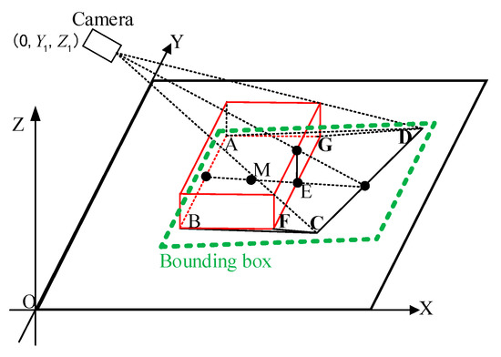
Figure 7.
PTZ Camera imaging model in our method.
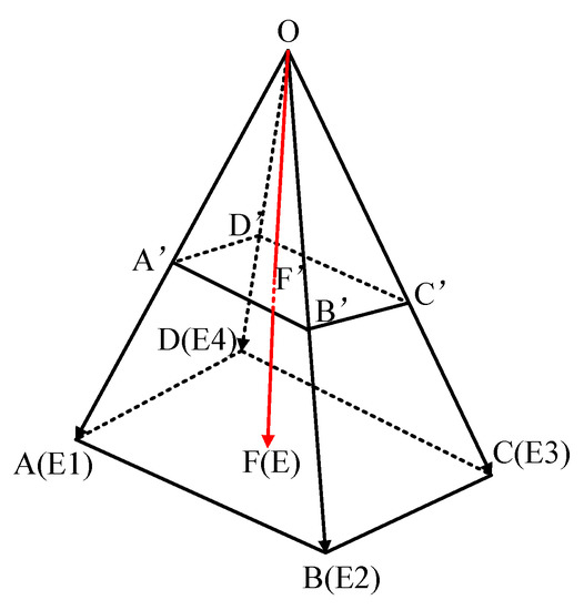
Figure 8.
Camera projection model.
Two projection models were constructed to calculate the target position. The first projection model is the position model, and the second is the error model. First, the initial position of the target in the world coordinate system is obtained through the position model. Then, the error of the corresponding point of the target in the world coordinate system is obtained through the error model. The position model and error model are shown in Formulas (15) and (16):
From Formulas (15) and (16), the initial coordinates of the target can be solved as . The coordinate error of the target on the image at point is . Finally, the precise world coordinates of the target can be derived:
3.4. Converts XYZ Coordinates to PTH Coordinates
As shown in Figure 9, the PTZ camera is regarded as a point, and the PTZ camera is located at point O. Set point O as the origin of the world coordinate system, and the coordinates of point A are . The ellipse in Figure 9 is on the ground in the real scene, and the vertices of the cell and the WRC-Jeep in the scene are regarded as points on the ground. According to the coordinate characteristics, it is easy to derive the following formula:
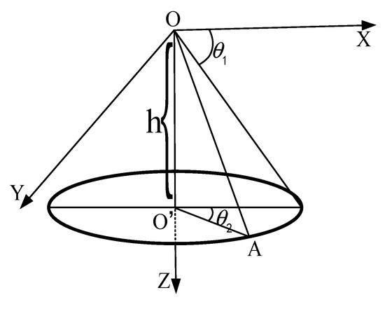
Figure 9.
Coordinate transformation model.
From the above formula,
According to Formulas (19) and (20), the unique , and H corresponding to point A can be calculated. Therefore, we call the model composed of , and H the PTH model.
4. Experimental Methods
4.1. Experimental Platform and Scene
The proposed method was tested on 50 cm ∗ 250 cm horizontal and vertical channels. The experimental equipment used in the experiment is shown in Figure 10. It mainly includes a PTZ camera. This active camera is produced by Hikvision Company. Its model is DS-2DF8231IW-A, the focal length range of this camera is 6 mm to 186 mm, it has two degrees of freedom of rotation, and the pan and tilt angles are between 0~90 degrees and 0~360 degrees, as shown in Figure 10. In this experiment, the resolution of the captured image is set to 1920 × 1080 (pixels). Another experimental device used in this experiment is a wireless remote-control car, as shown in Figure 10b. The length, width and height of the car are 22.5 cm, 14 cm and 13.5 cm, respectively.
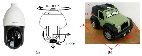
Figure 10.
Experimental equipment. (a) Active camera with pan and tilt functions. (b) Wireless remote-control Jeep car.
The experimental scene was modeled, and the world coordinate system was constructed (Figure 11a). We divided the operating channel of the WRC-Jeep into a horizontal channel (Figure 11c) and a vertical channel (Figure 11b) and divided each channel into five equally sized cells. The size of each cell was 50 cm ∗ 50 cm, and the vertices of each cell were calibrated. In addition, we calibrated the world coordinates of each vertex.
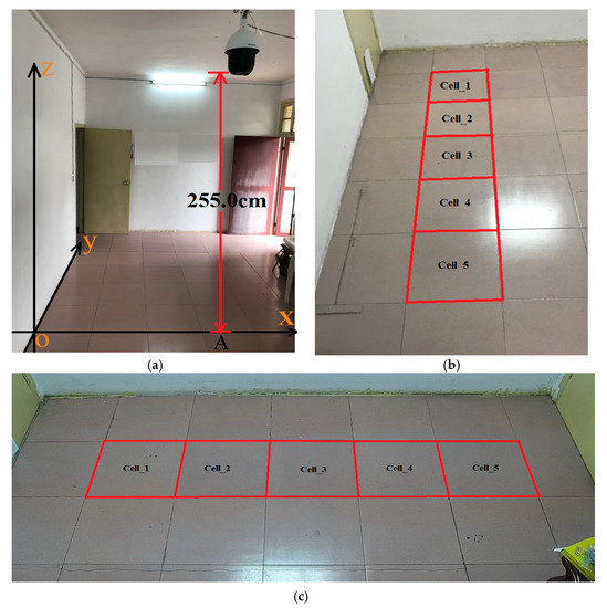
Figure 11.
Experimental scene. (a) Experimental scene modeling. (b) Vertical channel. (c) Horizontal channel.
Before the experiment, the camera needed to be calibrated. The results of camera calibration are as follows:
From the internal parameter matrix, the coordinates of the principal point of the camera can be obtained as: O′ = (963,557).
4.2. Training and Testing of Video Sequences with YOLOv4
This study uses the YOLOv4 algorithm to train and test the sample images. The targets used in the experiment are divided into two categories: “Jeep” and “cross”. The results of training and testing are shown in Table 1. The size of the sample picture selected in the experiment is 1920 (pixel) ∗ 1080 (pixel). A good recognition was achieved by applying YOLOv4 for training and testing (Table 1). A total of 6000 pictures were used for testing.

Table 1.
Training and testing result of YOLOv4.
4.3. Cell-Based Scene Division and Calibration
Before the experiment, we first built the world coordinate system in the scene, then divided the experimental scene into cells, and calibrated each vertex of each cell to calibrate the world coordinates of each vertex. At the same time, it was also necessary to calibrate the error of each vertex. That is, when the target center was located at the vertex of the cell from the perspective of the camera, we measured the position error of the WRC-Jeep in the real scene (including the error in the x-axis direction and the error in the y-axis direction) and calibrated all vertices with this method. The calibration results of the horizontal and vertical channels are in Table 2 and Table 3. XYZ represents the coordinates of each vertex, and errors represent the coordinate error of each vertex in the camera’s perspective.
Table 2.
Coordinates and errors of cell vertex on horizontal channel.
Table 3.
Coordinates and errors of cell vertex on vertical channel.
4.4. Experimental Result
Tests and verifications were carried out on the horizontal channel and the vertical channel to verify the effectiveness of the proposed method.
4.4.1. Horizontal Channel
We used YOLOv4 to detect the collected images. Figure 12 is a preliminary identification result.
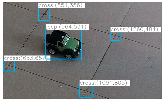
Figure 12.
Target detection results with YOLOv4.
The size of the image is 1920 (pixel) ∗ 1080 (pixel), so the coordinates of the image’s principal point are (963, 557). YOLOv4 detected the coordinates of each vertex (Figure 12). Then, the cell where the image principal point is located in the world coordinate system can be calculated by using the proposed cell recognition method. Then, the world coordinates and error coordinates of each vertex of the cell where the image principal point is located can be determined (Table 2 or Table 3). The homography matrix can be obtained according to the PnP algorithm. Then, the initial world and error coordinates of the WRC-Jeep can be obtained according to the image coordinates of the WRC-Jeep. The fourth column of Table 4 is the initial world coordinates of the WRC-Jeep, and the fourth column of Table 5 shows the error coordinates of the WRC-Jeep; the accurate world coordinates of the target can be solved.
Table 4.
Calculation results of target’s coordinates of horizontal channel.
Table 5.
Calculation results of error coordinates on horizontal channel.
Figure 12 and Table 4 and Table 5 show the test results of some frames. The complete trajectory and error of the WRC-Jeep in the horizontal channel are listed; the P value, T value and its error when using the PTZ camera to track and observe the target are listed as well. Finally, the specific results are shown in Figure 13 and Figure 14.
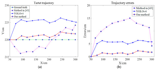
Figure 13.
Trajectory and PTZ errors of the target on the horizontal channel. (a) Target trajectory. (b) Trajectory errors [43].
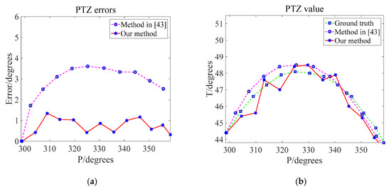
Figure 14.
Observation angle and angle error of the PTZ camera in the horizontal channel. (a) PTZ value. (b) PTZ errors [43].
4.4.2. Vertical Channel
We used the same method as the horizontal channel for testing. Figure 15 and Figure 16 show the results of the test under the vertical channel. Figure 15a shows the trajectory of the WRC-Jeep. Figure 15b shows the trajectory error of the WRC-Jeep detected by three different methods. Figure 15 shows the P and T values of the PTZ camera and shows the error between these P and T values with the real P and T values.
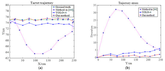
Figure 15.
Trajectory and trajectory error of the target on the vertical channel. (a) Target trajectory. (b) Trajectory errors [44].
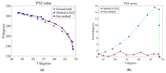
Figure 16.
Observation angle and angle errors of the PTZ camera in the vertical channel. (a) PTZ value. (b) PTZ errors [43].
According to the experimental results of the horizontal channel and vertical channel, the proposed method has better performance in tracking trajectory and tracking trajectory error. In addition, the value of the observation angle is closer to the ground truth of the observation angle, and the error of the observation angle is smaller than that of the previous method.
Finally, the recognition of the cell vertices is masked to display the position of the WRC-Jeep on the collected images. Then, the coordinates of the WRC-Jeep are displayed after the name of the WRC-Jeep (Figure 17).
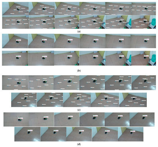
Figure 17.
Final recognition result. (a) Preliminary identification result of the horizontal channel. (b) Final identification result of the horizontal channel. (c) Preliminary identification result of the vertical channel. (d) Final identification result of the vertical channel.
5. Conclusions
This paper proposes a target localization and tracking method based on cells and an active camera. In this method, the experimental scene is divided into multiple continuous cells and the vertices of each cell are calibrated. The cell vertices and targets in the experimental scene are detected and recognized by the YOLOv4 algorithm. When the target was running in the experiment scene, we detected which image cell the image principal point was located in, and which cell of the real scene the projection point of the image principal point was located in. Then, we calculated the accurate world coordinates of the target at the current time using the projection model and converted the accurate world coordinates of the target into P, T, and H values using the PTH model for the purpose of tracking and observing the target in the experimental scene with the PTZ camera. This method can accurately locate the target position in the real scene and track the target quickly. The system proposed in this paper has the characteristics of robustness, accuracy, and easy installation.
The method proposed in this paper still has great room for improvement in the future. The proposed method is only implemented and verified in a small space and has good results. When the channel is long or the external conditions are complex, its effect needs to be examined. In addition, when the target runs in a fixed direction in the channel, it will have a better effect; when the target changes its travel attitude or direction in the channel, the target positioning error will increase exponentially.
Author Contributions
Conceptualization, J.Y. and Z.H.; data curation, J.Y. and Z.H.; funding acquisition, Z.H. and H.X.; project administration, Z.H. and C.X. All authors have read and agreed to the published version of the manuscript.
Funding
This research was funded by National Natural Science Foundation of China (NSFC) (No. 51679181), research project of provincial teaching reform in colleges and universities of Hubei Province (No. 2020809), guiding project of scientific research plan of Hubei Provincial Department of Education (No. B2021457, B2021563), Industry university cooperation collaborative education project (No. 202102191003).
Institutional Review Board Statement
Not applicable.
Informed Consent Statement
Not applicable.
Data Availability Statement
Data sharing is not applicable.
Acknowledgments
The author would like to thank all teachers and colleagues from Wuhan University of technology, and all involved in this research.
Conflicts of Interest
The authors declare no conflict of interest.
References
- Shorfuzzaman, M.; Hossain, M.S.; Alhamid, M.F. Towards the sustainable development of smart cities through mass video surveillance: A response to the COVID-19 pandemic. Sustain. Cities Soc. 2021, 64, 102582. [Google Scholar] [CrossRef] [PubMed]
- Tariq, S.; Farooq, H.; Jaleel, A. Anomaly detection with particle filtering for online video surveillance. IEEE Access 2021, 9, 19457–19468. [Google Scholar] [CrossRef]
- Pramanik, A.; Sarkar, S.; Maiti, J. A real-time video surveillance system for traffic pre-events detection. Accid. Anal. Prev. 2021, 154, 106019. [Google Scholar] [CrossRef] [PubMed]
- You, J.; Hu, Z.; Peng, C. Generation and Annotation of Simulation-Real Ship Images for Convolutional Neural Networks Training and Testing. Appl. Sci. 2021, 11, 5931. [Google Scholar] [CrossRef]
- López-Rubio, E.; Molina-Cabello, M.A.; Castro, F.M. Anomalous object detection by active search with PTZ cameras. Expert Syst. Appl. 2021, 181, 115150. [Google Scholar] [CrossRef]
- Arroyo, S.; Garcia, L.; Safar, F. Urban dual mode video detection system based on fisheye and PTZ cameras. IEEE Lat. Am. Trans. 2021, 19, 1537–1545. [Google Scholar] [CrossRef]
- Hu, J.; Zhang, C.; Xu, S. An Invasive Target Detection and Localization Strategy Using Pan-Tilt-Zoom Cameras for Security Applications. In Proceedings of the IEEE International Conference on Real-Time Computing and Robotics (RCAR), Xining, China, 15–19 July 2021; pp. 1236–1241. [Google Scholar]
- Meng, J.; Wang, S.; Xie, Y. Efficient re-localization of mobile robot using strategy of finding a missing person. Measurement 2021, 176, 109212. [Google Scholar] [CrossRef]
- Shao, C.; Zhang, L.; Pan, W. PTZ Camera-Based Image Processing for Automatic Crack Size Measurement in Expressways. IEEE Sens. J. 2021, 21, 23352–23361. [Google Scholar] [CrossRef]
- Comaniciu, D.; Meer, P. Mean shift: A robust approach toward feature space analysis. IEEE Trans. Pattern Anal. Mach. Intell. 2002, 24, 603–619. [Google Scholar] [CrossRef] [Green Version]
- Bradski, G.R. Computer vision face tracking for use in a perceptual user interface. In Proceedings of the IEEE Workshop on Applications of Computer Vision, Princeton, NJ, USA, 19–21 October 1998; pp. 214–219. [Google Scholar]
- Arulampalam, M.S.; Maskell, S.; Gordon, N. A tutorial on particle filters for online nonlinear/non-Gaussian Bayesian tracking. IEEE Trans. Signal Process. 2002, 50, 174–188. [Google Scholar] [CrossRef] [Green Version]
- Bertinetto, L.; Valmadre, J.; Henriques, J.F. Fully-convolutional siamese networks for object tracking. In Proceedings of the 14th European Conference on Computer Vision, Amsterdam, The Netherlands, 8–16 October 2016; pp. 850–865. [Google Scholar]
- Li, B.; Yan, J.; Wu, W. High performance visual tracking with siamese region proposal network. In Proceedings of the 2018 IEEE Conference on Computer Vision and Pattern Recognition, Salt Lake City, UT, USA, 18–22 June 2018; pp. 8971–8980. [Google Scholar]
- Li, B.; Wu, W.; Wang, Q. Siamrpn++: Evolution of siamese visual tracking with very deep networks. In Proceedings of the 2019 IEEE/CVF Conference on Computer Vision and Pattern Recognition, Los Angeles, CA, USA, 16–19 June 2019; pp. 4282–4291. [Google Scholar]
- Chen, K.; Tao, W. Once for all: A two-flow convolutional neural network for visual tracking. IEEE Trans. Circuits Syst. Video Technol. 2018, 28, 3377–3386. [Google Scholar] [CrossRef] [Green Version]
- Lukežič, A.; Zajc, L.Č.; Kristan, M. Deformable parts correlation filters for robust visual tracking. IEEE Trans. Cybern. 2017, 48, 1849–1861. [Google Scholar] [CrossRef] [PubMed] [Green Version]
- Wang, Q.; Gao, J.; Xing, J. Dcfnet: Discriminant correlation filters network for visual tracking. arXiv 2017, arXiv:1704.04057. [Google Scholar]
- Gundogdu, E.; Alatan, A.A. Good features to correlate for visual tracking. IEEE Trans. Image Process. 2018, 27, 2526–2540. [Google Scholar] [CrossRef] [PubMed] [Green Version]
- Gao, J.; Hu, W.; Lu, Y. Recursive least-squares estimator-aided online learning for visual tracking. In Proceedings of the 2020 IEEE/CVF Conference on Computer Vision and Pattern Recognition, Seattle, WA, USA, 14–19 June 2020; pp. 7386–7395. [Google Scholar]
- Du, F.; Liu, P.; Zhao, W. Correlation-guided attention for corner detection based visual tracking. In Proceedings of the 2020 IEEE/CVF Conference on Computer Vision and Pattern Recognition, Seattle, WA, USA, 14–19 June 2020; pp. 6836–6845. [Google Scholar]
- Bolme, D.S.; Beveridge, J.R.; Draper, B.A. Visual object tracking using adaptive correlation filters. In Proceedings of the 2010 IEEE Computer Society Conference on Computer Vision and Pattern Recognition, San Francisco, CA, USA, 13–18 June 2010; pp. 2544–2550. [Google Scholar]
- Henriques, J.F.; Caseiro, R.; Martins, P. Exploiting the circulant structure of tracking-by-detection with kernels. In Proceedings of the 2012 (12th) European Conference on Computer Vision, Firenze, Italy, 7–13 October 2012; pp. 702–715. [Google Scholar]
- Henriques, J.F.; Caseiro, R.; Martins, P. High-speed tracking with kernelized correlation filters. IEEE Trans. Pattern Anal. Mach. Intell. 2014, 37, 583–596. [Google Scholar] [CrossRef] [Green Version]
- Cimpoi, M.; Maji, S.; Vedaldi, A. Deep filter banks for texture recognition and segmentation. In Proceedings of the IEEE Conference on Computer Vision and Pattern Recognition, Boston, MA, USA, 7–12 June 2015; pp. 3828–3836. [Google Scholar]
- Danelljan, M.; Häger, G.; Khan, F. Accurate scale estimation for robust visual tracking. In Proceedings of the British Machine Vision Conference, Nottingham, UK, 1–5 September 2014. [Google Scholar]
- Danelljan, M.; Hager, G.; Shahbaz Khan, F. Learning spatially regularized correlation filters for visual tracking. In Proceedings of the IEEE International Conference on Computer Vision, Santiago, Chile, 13–16 December 2015; pp. 4310–4318. [Google Scholar]
- Bertinetto, L.; Valmadre, J.; Golodetz, S. Staple: Complementary learners for real-time tracking. In Proceedings of the 2016 IEEE Conference on Computer Vision and Pattern Recognition, Las Vegas, NV, USA, 27–30 June 2016; pp. 1401–1409. [Google Scholar]
- Danelljan, M.; Robinson, A.; Khan, F.S. Beyond correlation filters: Learning continuous convolution operators for visual tracking. In Proceedings of the 14th European Conference on Computer Vision, Amsterdam, The Netherlands, 8–16 October 2016; pp. 472–488. [Google Scholar]
- Danelljan, M.; Bhat, G.; Shahbaz Khan, F. Eco: Efficient convolution operators for tracking. In Proceedings of the IEEE Conference on Computer Vision and Pattern Recognition, Honolulu, HI, USA, 21–26 July 2017; pp. 6638–6646. [Google Scholar]
- Danelljan, M.; Bhat, G.; Khan, F.S. Atom: Accurate tracking by overlap maximization. In Proceedings of the IEEE/CVF Conference on Computer Vision and Pattern Recognition, Los Angeles, CA, USA, 16–19 June 2019; pp. 4660–4669. [Google Scholar]
- Liu, W.; Anguelov, D.; Erhan, D. Ssd: Single shot multibox detector. In Proceedings of the 14th European Conference on Computer Vision, Amsterdam, The Netherlands, 8–16 October 2016; pp. 21–37. [Google Scholar]
- Redmon, J.; Divvala, S.; Girshick, R. You only look once: Unified, real-time object detection. In Proceedings of the 2016 IEEE Conference on Computer Vision and Pattern Recognition, Las Vegas, NV, USA, 27–30 June 2016; pp. 779–788. [Google Scholar]
- Redmon, J.; Farhadi, A. YOLO9000: Better, faster, stronger. In Proceedings of the 2017 IEEE Conference on Computer Vision and Pattern Recognition, Honolulu, HI, USA, 21–26 July 2017; pp. 7263–7271. [Google Scholar]
- Redmon, J.; Farhadi, A. Yolov3: An incremental improvement. arXiv 2018, arXiv:1804.02767. [Google Scholar]
- Bochkovskiy, A.; Wang, C.Y.; Liao, H.Y.M. Yolov4: Optimal speed and accuracy of object detection. arXiv 2020, arXiv:2004.10934. [Google Scholar]
- Hu, Z.; Matsuyama, T.; Nobuhara, S. Cell-based visual surveillance with active cameras for 3D human gaze computation. Multimed. Tools Appl. 2015, 74, 4161–4185. [Google Scholar] [CrossRef]
- Farajzadeh, N.; Karamiani, A.; Hashemzadeh, M. A fast and accurate moving object tracker in active camera model. Multimed. Tools Appl. 2018, 77, 6775–6797. [Google Scholar] [CrossRef]
- Liu, N.; Wu, H.; Lin, L. Hierarchical ensemble of background models for PTZ-based video surveillance. IEEE Trans. Cybern. 2014, 45, 89–102. [Google Scholar] [CrossRef]
- Kang, S.; Paik, J.K.; Koschan, A. Real-time video tracking using PTZ cameras. In Proceedings of the Sixth International Conference on Quality Control by Artificial Vision, Gatlinburg, TN, USA, 29–30 April 2003; pp. 103–111. [Google Scholar]
- Lisanti, G.; Masi, I.; Pernici, F. Continuous localization and mapping of a pan–tilt–zoom camera for wide area tracking. Mach. Vis. Appl. 2016, 27, 1071–1085. [Google Scholar] [CrossRef] [Green Version]
- Shakeri, M.; Zhang, H. Cooperative targeting: Detection and tracking of small objects with a dual camera system. In Proceedings of the Field and Service Robotics, Toronto, ON, Canada, 24–26 June 2015; pp. 351–364. [Google Scholar]
- Baris, I.; Bastanlar, Y. Classification and tracking of traffic scene objects with hybrid camera systems. In Proceedings of the 20th International Conference on Intelligent Transportation Systems (ITSC), Yokohama, Japan, 16–19 October 2017; pp. 1–6. [Google Scholar]
- Hu, Z.; You, J.; Yuan, K. Grid-based Control of Active Cameras for Waterway Ship Surveillance. In Proceedings of the 5th International Conference on Transportation Information and Safety (ICTIS), Liverpool, UK, 14–17 July 2019; pp. 1319–1323. [Google Scholar] [CrossRef]
Publisher’s Note: MDPI stays neutral with regard to jurisdictional claims in published maps and institutional affiliations. |
© 2022 by the authors. Licensee MDPI, Basel, Switzerland. This article is an open access article distributed under the terms and conditions of the Creative Commons Attribution (CC BY) license (https://creativecommons.org/licenses/by/4.0/).