Abstract
The semi-fixed dowel joint studied in this paper consists of a steel dowel with rubber sleeves and a rubber pad to connect the superstructure and the substructure and to support the main beam. This type of joint is suitably used in retrofitting a jointed bridge with high-stiffness substructure into a semi-integral bridge. This study aimed to investigate the nonlinear stiffness of the joint, which is the key parameter in the retrofitting design. Taking the real joint in a retrofitted semi-integral bridge as a prototype, tests on full-scale models were carried out, in which the wall thickness of the rubber sleeve and the thickness of the rubber pad were taken as parameters. The test results show that the wall thickness of the rubber sleeve is the main factor affecting the radial stiffness and the flexural stiffness of the semi-fixed dowel joint. With the decrease of the wall thickness of the rubber sleeve, the radial stiffness decreases while the flexural stiffness increases. However, the thickness of the rubber pad has little influence on both the radial and flexural stiffness of the joint, and its main role is only vertical loading-bearing. If the longitudinal deformation of the main beam of a bridge under maximum temperature variation is 10 mm as the allowance value of engineering design, the wall thickness of the rubber sleeve for this joint should not be less than 40 mm. At last, on the basis of experimental research and theoretical analysis, the formulas of radial stiffness and flexural stiffness are fitted; it can be used as reference for practical engineering application, or for formulation of relevant specifications.
1. Introduction
Most small and medium span bridges are simply supported beam-type structures. In order to accommodate the variation of ambient temperature, expansion joints are usually arranged between beams and abutments, and between adjacent spans for multi-span bridges. Expansion joints often become the weakest parts of bridges, bringing adverse effects to traffic and bridge structure. Their maintenance and replacement consume a lot of manpower, material resources and costs. An effective solution is to retrofit them into integral abutment bridges (IABs), in which the expansion gaps, expansion joints and bearings can be eliminated by integrating the superstructure and the abutments [1,2]. An IAB is a statically indeterminate structure in longitudinal direction due to these rigid connections, and the substructure stiffness has a significant effect on the stress level induced by thermal loads in the structure [3,4,5,6]. For new IABs, flexible piles like H-shaped steel piles or concrete piles with an enclosure of the top part by a rubber sleeve or filled with loose sand can be used as the foundation [7,8]. However, for most of the existing bridges with expansion joints (jointed bridges), the stiffness of the substructures are generally high and integral design is not feasible; thus, the semi-integral abutment bridges (SIABs) are used to be an alternative of jointless bridges [3,9,10].
In a SIAB, the superstructure may rest on conventional bearings at abutments, and moves longitudinally independent of the abutments. In order to reduce the detrimental effects of temperature-induced displacements, the Virginia Department of Transportation (VDOT) in the USA developed the dowel joints for semi-integral abutment bridges, in which the dowels protruded into the superstructure were loosely wrapped with three layers of roofing felt. Tests on the two types of joints were carried out; one was the original type with a shear key but without a pad, while the other was the revised type without a shear key, instead it used a pad as bearing. Test results showed that the dowel joints could significantly reduce the moments transferred from the superstructure to the foundation piles. The original joints experienced the shear key failure, while the revised ones did not exhibit this behavior and showed no sign of damage during the tests [11]. In the rehabilitation of the Jingpu Bridge transformed from a simply supported structure into a SIAB, dowel joints wrapped by rubber sleeves were used [12]. The rubber sleeve can provide space for the daily small thermal movements with small restraint, while the steel dowel can control the extra movements induced by seasonal temperature by transmitting shear forces from superstructure to substructure, the steel dowel can prevent fatigue failure caused by daily thermal movements. In addition, a rubber (neoprene) pad is used for the proper sitting of the superstructure on the substructure, to ensure the even distribution of the stresses at the bearing face and allow small thermal movements. The rubber sleeve and rubber pad will make the dowel joint behave nonlinearly, and the joint becomes a semi-fixed one. The nonlinear stiffness of the semi-fixed dowel joint has an impact on the performance of SIABs, and is the key parameter in the design calculation.
Dowel joints are used widely in buildings because they can play an important role in seismic energy dissipation of a structure and an unseating prevention system. Research studies up to now have mainly focused on their seismic energy dissipation capacity [13,14,15]. The studs used in the rehabilitation of the Isola Della Scala bridge transformed from a simply supported structure into an IAB can be considered as dowels, in which the push-out test of the stud was carried out [16]. However, the studs had no rubber sleeve and were used together with expansive concrete mortar incorporated with the existing bearings; accordingly, the connection between the superstructure and substructure is rigid. Studies on nonlinear stiffness of semi-fixed dowel joints in SIABs are lacking in the literature.
In this study, the real semi-fixed dowel joints used in the Jingpu Bridge were adopted as a prototype; tests on full-scale models were carried out to investigate their nonlinear stiffness by being taken as the parameters of the wall thickness of the rubber sleeve and the thickness of the rubber pad. The main findings of the experimental study are presented and a calculation formula for the stiffness is proposed.
2. Introduction to the Jingpu Bridge
The semi-fixed dowel joints used in the retrofitted Jingpu Bridge were taken as the prototype of the model tests in this study. The Jingpu Bridge is located on the Provincial Road 208 in the Suburb of Zhangzhou City, Fujian Province, China, where it is close to the Zhangzhou Railway Station with heavy traffic. The original bridge built in early 1990s has three spans of simply supported adjacent precast prestressed concrete (PC) slabs together with a continuous 10 cm thick cast-in-place link slab over piers. Each span was 16 m long, and the slab had a width of 124 cm and a depth of 80 cm. Two expansion joints were arranged between slab ends and the back wall of the abutments. The substructure consisted of a reinforced concrete column pier and abutments supported on piles. Each pier or abutment has dual columns with diameters of 1.0 m and dual-bored piles with diameters of 1.2 m as well as a capping beam 1.2 m wide and 1.2 m deep. The whole length of the bridge was 52.8 m, and the total width was 30 m [12].
After about 20 years of service, the Jingpu Bridge’s condition had degenerated seriously. According to the inspection carried out in 2010, the main problems of the bridge occurred in the superstructure, including longitudinal and transverse cracks of the slab beams and decks, steel bar corrosion and concrete carbonation of the slab beams, concrete crush in link slabs and in the vicinity of the expansion joints. After the inspection, the condition evaluation of the bridge was performed according to the Chinese standards for technical condition evaluation (JTG/T H21-2011) [17], in which the technical condition of a bridge was evaluated to a grade of 1–5, with 1 being the best and 5 representing the worst condition. The condition score of the Jingpu Bridge was only 30.8 and rated as level 4 in the evaluation, exhibiting very poor conditions of the bridge for service. Therefore, a plan for its strengthening and retrofitting plan was proposed.
Due to the substructure of the bridge being in good technical condition, it was determined that the strengthening and retrofitting of the bridge is only focused on the superstructure. All the deteriorated simply supported PC voided slabs were replaced by new fabricated PC voided slabs, which were first erected as simple spans and then made continuous by pouring concrete between the adjacent spans, so that no link slabs over the piers were necessary to make adjacent spans continuous again. The slab beams and the abutments were connected together and the expansion joints between them were eliminated in the retrofitted structure. The superstructure was supported on piers and abutments with the semi-fixed dowel joints to form a jointless bridge with semi-integral abutments and semi-integral piers (semi-integral bridge in short). The semi-fixed dowel joint was composed of a rubber pad and a steel dowel with a rubber sleeve, which were also called a pad and dowel bearing. The square rubber pad used in this bridge has a thickness of 40 mm and a side length of 600 mm. The steel dowel had a diameter of 32 mm and a length of 1520 mm, buried in the capping beams for 1000 mm, went through the pad for 40 mm and extended into the slab beam 480 mm. Steel bars were wrapped with a rubber sleeve with an inner diameter of the 32 mm, wall thickness of 40 mm and length of 520 mm. Each slab beam in the transverse direction has two semi-fixed dowel joints with a spacing of 400 mm, as illustrated in Figure 1. The bridge elevation before and after retrofitting is shown in Figure 2. The bridge was retrofitted from July 2014 to November 2014.
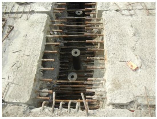
Figure 1.
Semi-fixed dowel joints in the Jingpu Bridge.
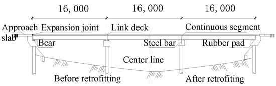
Figure 2.
Elevation of the Jingpu Bridge before and after retrofitting.
3. Experimental Program
3.1. Specimens
A specimen consisting of the dowel joint components and the upper and bottom concrete blocks was fabricated to simulate the superstructure and the substructure of the bridge, as shown in Figure 3. The steel dowel in the dowel joint had the same diameter of 32 mm as in the real structure, and its 380 mm length was buried into the bottom block and 480 mm was extended into the upper block. The steel dowel was wrapped with a rubber sleeve, and a rubber pad was arranged between the upper and bottom block of the specimen.
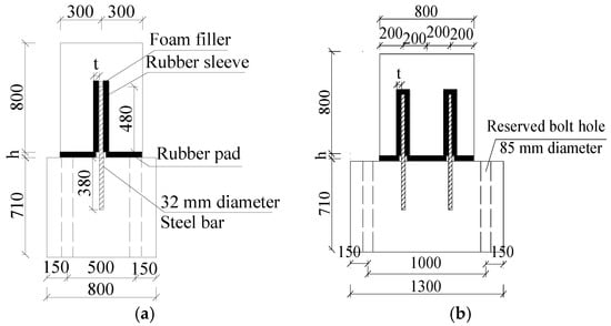
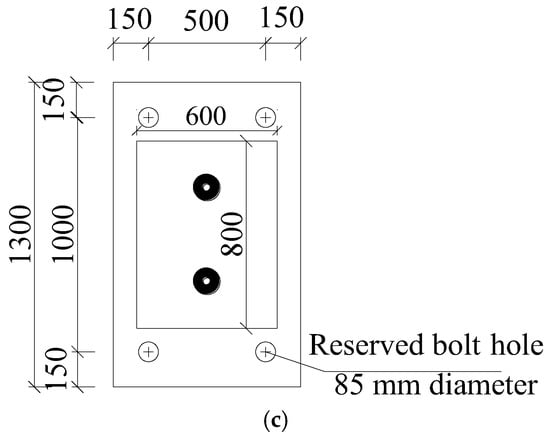
Figure 3.
Specimen dimension of the semi-fixed dowel joint (unit: mm). (a) Side view. (b) Front view. (c) Top view.
The wall thickness of the rubber sleeve, t, and the thickness of the rubber pad, h, were taken as the main parameters.
The rubber sleeve had an inner diameter the same as the diameter of the steel dowel, that is, 32 mm. With 40 mm as the basic wall thickness as in the real structure, 20 mm thicker and 20 mm thinner of the wall was taken for the wall thickness variation, which results in three specimens with different wall thicknesses of rubber sleeves, i.e., 20 mm, 40 mm and 60 mm. The rubber pad had a plan dimension of 800 mm × 600 mm, with its basic thickness of 40 mm, The thickness of another contrast specimen is 20 mm. Therefore, a total of 4 specimens were designed and fabricated, as listed in Table 1.

Table 1.
Specimen parameters (unit: mm).
The dimension of the upper concrete block is 800 mm × 600 mm × 800 mm, and the bottom block is 1300 mm × 800 mm × 710 mm for the specimen with a rubber pad thickness of 40 mm; it was 1300 mm × 800 mm × 730 mm when the rubber pad thickness was 20 mm. The specimen dimension is shown in Figure 3.
Considering the concrete blocks of the specimens would work as rigid bodies in the test and only very small stresses would be produced, they were only reinforced with longitudinal steel bars with a diameter of 16 mm and stirrups, less than the actual reinforcement in the bridge. The reinforcement is not drawn in Figure 3.
The concrete strength grade used for the specimens was C35 concrete, which means that its compression strength of cubic specimen with 150 mm side length is 35 MPa. The concrete sample prepared and cured under the same conditions as used for the corresponding specimens were tested, giving an average compressive strength of 36.7 MPa from three samples.
Three samples of steel bars were taken for material property test. The measured yielding strength and tensile strength were 402.7 MPa and 510.8 MPa, respectively. According to JGJ D62-2004 [18], the elastic modulus is set to 2.0 × 10⁵ MPa. The rubber properties are provided by the manufacturer, as shown in Table 2.
Table 2.
Rubber properties in the semi-fixed dowel joints.
3.2. Loading and Instrumentation
A 100 kN vertical load was applied at the top center of the specimen by means of a vertical hydraulic jack during the whole process of the testing. The horizontal force was applied by means of MTS servo hydraulic loading system, as shown in Figure 4. The test was controlled by displacement.
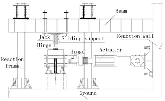
Figure 4.
Loading device.
Strain gauges were placed on opposite surfaces of each dowel to monitor bending strains, in which “F” and “B” of the gauge mean in front and back of the loading, as shown in Figure 5. The strain gauges were only arranged in the part buried into the bottom concrete block as well as the part through the rubber pad, but not in the part inside the upper block, because they would be damaged by the relative displacement between the rubber sleeve and the steel dowel during the test. In the strain gauge numbers, ”L” and ”R” represent the left and right sides of the steel dowel.
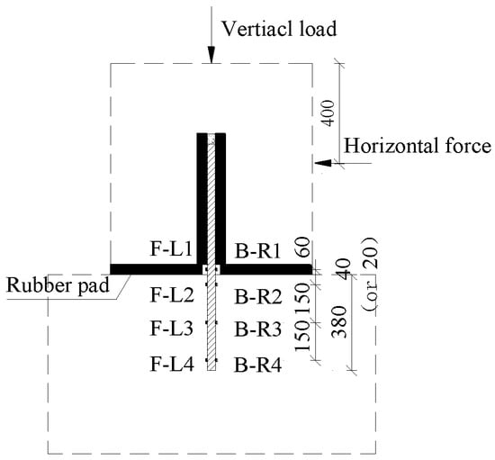
Figure 5.
Strain gauge arrangement on the steel dowel (unit: mm).
Four displacement gauges and one inclinometer were placed along the front of the concrete structure (perpendicular to the loading direction), as shown in Figure 6a, to measure the relative horizontal displacement and inclination angle of the upper concrete block. Two displacement gauges at the bottom concrete block were used to measure its horizontal displacement. Another four displacement gauges were placed on the top surface of the upper concrete block, as shown in Figure 6b, to measure the rotation angle of the joint and the vertical displacements caused by rotation. The vertical displacement measured by these four displacement gauges and the inclination angle obtained from the inclinometer can be used to check each other.
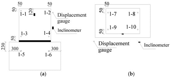
Figure 6.
Arrangement of displacement meter and inclinometer (unit: mm). (a) Front view. (b) Top view.
4. Test Results
4.1. Loading Displacement—Horizontal Displacement Curve
In the loading process, the maximum vertical displacement of the rubber pad was only 0.5 mm, and its influence on the horizontal displacement of the joint can be ignored. The measured horizontal displacement of No. 1–4 displacement gauge (Figure 6a) on the bottom edge of the upper concrete block minus the displacement affected by the rotation is the horizontal displacement of the upper concrete block. The curves of loading displacement–horizontal displacement of the specimen from the test are shown in Figure 7.
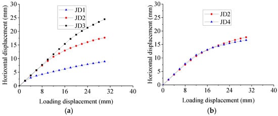
Figure 7.
Loading displacement–horizontal displacement curve of semi-fixed dowel joint. (a) Thickness of rubber sleeve. (b) Thickness of rubber pad.
It can be seen from Figure 6 that the horizontal displacement of the joint increases with the increase of loading displacement. The mechanical behaviors of the specimens can be roughly divided into two stages on the curves: elastic stage and plastic stage. As illustrated by Figure 7a, before the loading displacement of JD1, JD2 and JD3 was 6 mm, 10 mm and 16 mm, respectively, the loading displacement–horizontal displacement curve was a straight line, and the rubber sleeve was mainly subjected to radial compression; the specimen worked elastically. After that, the specimens entered the plastic stage with a gentle change of the tangent slope of the loading displacement–horizontal displacement curve, and the deformation of the specimens was mainly the rotation. In the case of the same rubber pad, the upper horizontal displacement of the joint at the second stage increased with the decrease of thickness the rubber sleeve.
From the comparison of specimens JD2 and JD4 with different thicknesses of rubber pad in Figure 7b, it can be found that the two curves are nearly close to each other. Further comparison can find that the maximum difference of the horizontal displacement between them was only 6.2%, indicating that the rubber pad has little influence on horizontal displacement of the joint; consequently, its influence can be ignored in analysis of the nonlinear stiffness of the semi-fixed dowel joint.
4.2. Rotation Angle
Figure 8 shows the relation curve between the loading displacement of the semi-fixed dowel joint and the rotation angle (denoted by θ; unit: °). In addition, the rotation angle converted based on the measured displacement is almost the same as that measured by the inclinometer.
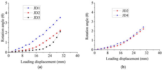
Figure 8.
Loading displacement–rotation angle curve of semi-fixed dowel joint. (a) Thickness of rubber sleeve. (b) Thickness of rubber pad.
It can be seen from Figure 8a that the rotation angle of the joint increases with the increase of loading displacement, and the curve can also be divided into two sections. The rotation angle of JD1, JD2 and JD3 is in a straight line before the loading displacements of 6 mm, 10 mm and 14 mm, respectively, and in a rising curve at the later stage. The rotation angle decreases significantly with the decrease of the wall thickness of rubber sleeve. The reason is that the larger radial compression deformation of the thicker rubber sleeve dominates the deformation of the joint.
Similar to the comparison of horizontal displacement in Figure 8b, the rotation angles of specimens JD2 and JD4 with different thicknesses of the rubber pad were almost the same. Therefore, the rubber pad has little influence on the rotation angle of the joint, which further indicates that the influence of the thickness variation of the rubber pad on the nonlinear stiffness of the semi-fixed dowel joint can be ignored.
4.3. Strain of Steel Dowel
The measured strains on both sides of the steel dowel are basically closed in values. Therefore, only one side of the steel bar was analyzed for tensile strain gauge, as shown in Figure 9. From Figure 9 of the loading displacement–steel bar strain curve of B-R1, it can be seen that the strain of steel bar can be divided into two stages: elastic stage and plastic stage. After the loading displacements of 8 mm, 10 mm and 12 mm, respectively, the steel bar began to yield and entered into plastic deformation.
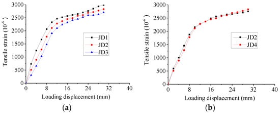
Figure 9.
Loading displacement–steel bar strain curve of B–R1. (a) Thickness of rubber sleeve. (b) Thickness of rubber pad.
By comparing the influences of different thicknesses of rubber sleeves in Figure 9a, it can be seen that the strain of steel bar increased with the decrease of the wall thickness of the rubber sleeve. The reason is that, the smaller the wall thickness of rubber sleeve, the larger the rotation angle and flexural-tensile strain of the steel bar. By comparing JD2 and JD4 with different thicknesses of rubber pads in Figure 9b, it can be seen that the two curves are almost the same, indicating that the thickness of the rubber pad has little influence on the stiffness of the steel bar within the range of test parameters, which can be ignored.
Figure 10 shows the relationship of loaded displacement versus strains of B-R1, B-R2 and B-R3 on the steel dowel in specimen JD2, where strains of B-R4 are not presented due to too small values. The steel strains decreased from top to bottom, where the largest strains came from B-R1 at the location of the rubber pad, which were in the elastic range at the first loading stage, and then entered into the plastic range. However, the strains of B-R2 and B-R3 buried in the concrete block were always in the elastic stage.
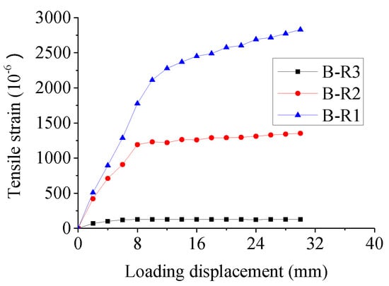
Figure 10.
Relationship of loading displacement versus strain of steel dowel in Specimen JD2.
Figure 11 shows the relationship of loaded displacement versus strains of B-R2 and B-R3 on steel dowels in specimens of JD1, JD2 and JD3, respectively, to investigate the influence of the thickness of the rubber sleeve. For the same loaded displacement, the strains of both B-R2 and B-R3 from largest to smallest appeared in the specimens from JD1 to JD2 to JD3.
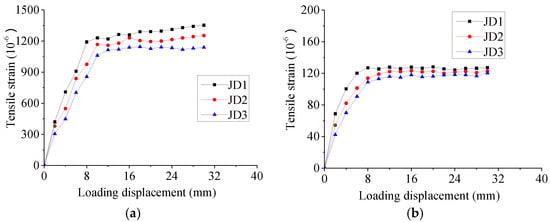
Figure 11.
Relationship of loading displacement versus strain of B–R2 and B–R3 in specimen with a variation of thickness of rubber sleeve; (a) B–R2; (b) B-R3.
In the whole loading process, the steel dowels can be divided into two stages. At the first stage, strains increased linearly with the load, and the main deformation of the steel dowel was bending. Then, the bending deformation concentrated on the gap (occupied by the rubber pad) between the upper and bottom blocks, and the steel dowel began to yield. The strains of the steel dowel embedded in the bottom concrete block were all in elasticity, and their values decreased with the deeper buried location.
Based on the above analysis, the mechanical properties of dowel joints are significantly affected by the wall thickness of the rubber sleeve, but less affected by the thickness of the rubber pad. Therefore, if the deformation of 10 mm in the longitudinal direction caused by the maximum temperature effect of the beam is taken as the design allowable value, the wall thickness of the rubber sleeve should not be less than 40 mm to ensure that the dowel joint behaves in the linear elastic range for the case studied.
5. Stiffness Analysis
5.1. Isolator and Basic Equilibrium Formula
To calculate the stiffness of the joint, the top surface of the rubber pad was taken as the cutting surface and the upper isolator was taken out, as shown in Figure 12.
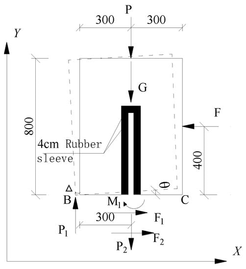
Figure 12.
Isolator for calculation of force on the joint (unit: mm).
The force balance of the joint in the X and Y directions and the moment balance around the long edge of the concrete body can be expressed by Formulas (1)–(5).
where F is the loading force (kN). F1 is the friction between rubber pad and concrete (kN); and F2 is the sheer force of the steel bar (kN). P is the vertical loading force (kN). P1 is the bracing reaction (kN) of the rubber pad to the isolator. P2 is the friction between the steel bar and the rubber sleeve (kN) and M1 is the bending moment of the steel bar (kN·mm). G is the self-weight of the upper concrete block (kN). The △ is the horizontal displacement of the lower edge of the upper concrete block (mm). and are friction coefficients between rubber and concrete and between rubber and steel, respectively.
5.2. Radial Stiffness
The horizontal displacement of the upper concrete block of the specimen is illustrated in Figure 7a. The ratio of the actual horizontal force (F2) on the joint to the horizontal displacement of the upper part of the specimen is the radial stiffness of the specimen in longitudinal direction.
For the specimens in this paper, the friction coefficients in Formulas (4) and (5) were set as [19] and [20], respectively. The radial stiffness and rotational stiffness of the joint are obtained by substituting them into the test results.
Figure 13a gives the curves of loading displacement–radial stiffness of specimens JD1, JD2 and JD3 with the wall thickness of the rubber sleeve as the parameter. The radial stiffness of the specimens decreased greatly before the loading displacement of 16 mm, and then gently decreased, and the curves were approximately straight lines. The radial stiffness of the joint increases with the decrease of the wall thickness of rubber sleeve. The maximum radial stiffness of JD1, JD2 and JD3 are 27.7 kN/mm, 12.6 kN/mm and 8.4 kN/mm, respectively.
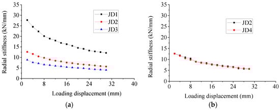
Figure 13.
Loading displacement–radial stiffness curve of semi-fixed dowel joint. (a) Wall thickness of rubber sleeve. (b) Thickness of rubber pad.
From Figure 13b, it can be found that the radial stiffness of JD2 is slightly smaller than that of JD4, the maximum difference between them is only 6.1%, indicating that the thickness of the rubber pad has little influence on the radial stiffness.
Radial deformation of the rubber sleeve in the tube can be obtained by assuming that the sleeve is composed of two independent rubber blocks; one block has a compressive deformation, while the other one has no deformation [21]. The size of the rubber block can be taken as follows: the length is l (height of the rubber sleeve), the width is half of the average circumference, and the thickness δ is the thickness of the rubber dowel sleeve. Based on the force balance of the rubber block, the radial stiffness of the rubber sleeve in the tube is as follows:
where is the radial stiffness of rubber sleeve in tube (N/mm), is the height of the sleeve (mm); are the inner and outer radii of the rubber sleeve (mm), respectively; δ is the wall thickness of the rubber sleeve (mm), and ; E is modulus of elasticity of rubber (N/mm2).
The lower end of the rubber sleeve in the semi-fixed dowel joint is constrained by the steel dowel, the upper end of the rubber sleeve is free, and the force on the rubber sleeve is not uniform. It can be seen from Figure 13 that the radial stiffness of the joint varies nonlinearly with the loading displacement. The ratio of it to the loading displacement X and the inner radius of rubber sleeve r1 is logarithmic. It can be calculated by Formula (7).
where is the radial stiffness of the semi-fixed dowel joint (N/mm); X is the loading displacement (mm); α and β are coefficients.
The coefficients α and β are undetermined, related to the inner radius and outer radius of the rubber sleeve, and they are dimensionless. After regression of test data, the following formula can be obtained:
By substituting α and β into Formula (7), the calculation of Formula (8) of radial stiffness can be obtained.
where X is the loaded displacement, which is taken as 2 mm when X is less than 2 mm, the maximum loading displacement is 30 mm in the process of test.
In the test, the acted load was controlled by the displacement, which was started from 2 mm. Therefore, Formula (8) is only feasible to the stiffness from the acted displacement 0~2 mm. It can be seen from Figure 8a that the maximum rotation angle of each specimen was 0.08° when the loading displacement was 2 mm. It can be considered that when the loading displacement was 0–2 mm, only the rubber sleeve was compressed, and no rotation was occurred in the joint. Therefore, the radial stiffness at the loading displacement of 2 mm can be considered as the initial radial stiffness for the acted displacement from 0~2 mm. In other words, x is taken as 2 when it is less than 2 mm in Formula (8).
5.3. Flexural Stiffness
Figure 14 shows the curves of loading displacement–flexural stiffness of the tested semi-fixed dowel joints. The flexural stiffness of all the joint specimens exhibited non-linear behavior. They decreased rapidly with the increase of the loading displacement before the loading displacement was 8 mm, and then decreased gently and the curves showed almost straight lines. The flexural stiffness of the joint was greatly affected by the wall thickness of rubber sleeve. The maximum flexural stiffness of JD1, JD2 and JD3 are 334.04 kN·m/θ, 450.07 kN·m/θ and 529.79 kN·m/θ, respectively.

Figure 14.
Loading displacement–flexural stiffness curve of semi-fixed dowel joint. (a) Wall thick–ness of rubber sleeve. (b) Thickness of rubber pad.
With regard to the thickness of the rubber pad, it can be seen from Figure 14 that the flexural stiffness of JD4 was only slightly smaller than that of JD2, with the maximum difference of only 3.7%. Therefore, the very small influence of the thickness of the rubber pad on the flexural stiffness of the joint can be negligible.
It can be seen from Figure 14 that the flexural stiffness of each joint differs greatly at the loading displacement of 2~4 mm, and each curve in this portion is in straight lines; after that, all curves are close to each other and demonstrate nonlinearity with the loading displacement. Thus, the flexural stiffness of the joint can be expressed by a function of two portions:
where are, respectively, flexural stiffness of the semi-fixed dowel joint in a straight line and a curve (N). is the inertia moment of the rubber sleeve (. are coefficients and dimensionless, and are related to the inner radius and outer radius of the rubber sleeve. X is the loaded displacement (mm), which is taken as 2 mm when X is less than 2 mm in Formula (9a), due to the same reason as that for Formula (8).
After regression of test data, the following formulas can be obtained:
Substituting the above formulas into Formula (9), we can obtain the expressions to predict the flexural stiffness by Formula (10).
where X is the loaded displacement (mm), taken as 2 mm when X is less than 2 mm, the maximum loading displacement is 30 mm in the process of test.
6. Summary and Conclusions
Taking the real joint in a retrofitted jointless bridge as a prototype, full-scale semi-fixed dowel joints were tested, their nonlinear stiffness were analyzed, and the following conclusions can be drawn in this paper:
(1) The horizontal and rotation displacement of the semi-fixed dowel joint increase with the increase of loading displacement. At the beginning of loading, the deformation of the joint was mainly caused by compression of the rubber sleeve, and then by rotation of the joint.
(2) The steel dowels in the semi-fixed dowel joints behaved from the elastic stage to the elastic–plastic stage in the whole loading process. The strains measured from the bottom concrete block were all in the elastic ranges, and the values decreased as strain gauges are located from shallow to deeper.
(3) The relationships between the radial stiffness or flexural stiffness of the semi-fixed dowel joint and the loading displacement are nonlinear. The stiffness decreases with the increase of the loading displacement, and is affected greatly by the wall thickness of the rubber sleeve around the steel dowels. However, the influence of the thickness of the rubber pad is small and can be ignored in practical engineering.
(4) If the deformation of 10 mm in the longitudinal beam caused by the maximum temperature effect is taken as the design allowable value, the wall thickness of the rubber sleeve should not be less than 40 mm in order to ensure that the dowel joint behaves in the linear elastic range for the case studied.
(5) According to the test results and mechanical analysis, the calculation formula for radial and flexural stiffness of semi-fixed dowels were proposed, which is an interesting topic for further research by more specimen tests and numerical analysis.
Author Contributions
All authors substantially contributed to this work. Z.X. designed and fabricated the semi-fixed dowel joint model. Z.X. and X.L. designed the experiment. Z.X. and F.S. performed the experiments and analysis. B.C. and Z.X. wrote the paper. B.C., F.H. and Y.Z. revised and finalized the paper. All authors helped with the writing of the paper. All authors have read and agreed to the published version of the manuscript.
Funding
This research was funded by the National Natural Science Foundation of China with Grant Numbers 51578161.
Institutional Review Board Statement
Not applicable.
Informed Consent Statement
Not applicable.
Data Availability Statement
The data used to support the findings of this study are available from the corresponding author and upon request.
Conflicts of Interest
The authors declare no conflict of interest.
References
- Xu, Z.; Chen, B.; Zhuang, Y.; Tabatabai, H.; Huang, F. Rehabilitation and Retrofitting of a Multi-Span Simply-Supported Adjacent Box Girder Bridge into a Jointless and Continuous Structure. J. Perform. Constr. Facil. 2018, 32, 04017112. [Google Scholar] [CrossRef]
- Hassiotis, S.; Roman, E.K. A survey of issues on the use of integral abutment bridges. Bridge Struct. 2005, 1, 81–101. [Google Scholar] [CrossRef]
- Burke, J.; Martin, P. Integral and Semi-Integral Bridges; Wiley-Blackwell: Oxford, UK, 2009. [Google Scholar]
- Cehn, B.-C.; Zhuang, Y.-Z.; Huang, F.; Briseghella, B. Jointless Bridge, 2nd ed.; China Communication Press: Beijing, China, 2019. (In Chinese) [Google Scholar]
- Dunker, K.F.; Liu, D. Foundations for Integral Abutments. Pract. Period. Struct. Des. Constr. 2007, 12, 22–30. [Google Scholar] [CrossRef]
- Albhaisi, S.; Nassif, H.; Hwang, E. Effect of Substructure Stiffness on Performance of Steel Integral Abutment Bridges under Thermal Loads. Transp. Res. Rec. 2012, 2313, 22–32. [Google Scholar] [CrossRef]
- Huntley, S.A.; Valsangkar, A.J. Behavior of H-Piles Supporting an Integral Abutment Bridge. Can. Geotech. J. 2014, 51, 713–734. [Google Scholar] [CrossRef]
- Naji, M.; Firoozi, A.A.; Firoozi, A.A. A review: Study of integral abutment bridge with consideration of soil-structure interaction. Lat. Am. J. Solids Struct. 2020, 17, 1–27. [Google Scholar] [CrossRef]
- Russo, G.; Bergamo, O.; Damiani, L. Retrofitting a Short Span Bridge with a Semi-Integral Abutment Bridge: The Treviso Bridge. Struct. Eng. Int. 2009, 19, 137–141. [Google Scholar] [CrossRef]
- Kim, S.H.; Ahn, J.H.; Jung, C.Y.; Jang, J.W.; Park, Y.H. Behavior of Steel-Box Semi-integral Abutment Bridge Considering Temperature-earth Pressure Change. Int. J. Steel Struct. 2014, 14, 117–140. [Google Scholar] [CrossRef]
- Arsoy, S.; Duncan, J.M.; Barker, R.M. Behavior of a Semi-integral Bridge Abutment under Static and Temperature-Induced Cyclic Loading. J. Bridge Eng. 2004, 9, 193–199. [Google Scholar] [CrossRef]
- Dong, J.C.; Chen, B.C.; Briseghella, B.; Zhuang, Y.Z. Integral Transformation Design of Multi-Span Hollow Slab Simply-Supported Bridge. J. Archit. Civ. Eng. 2015, 32, 73–80. (In Chinese) [Google Scholar]
- Seo, J.; Rogers, L.P.; Hu, J.W. Computational seismic evaluation of a curved prestressed concrete I-girder bridge equipped with shape memory alloy. Eur. J. Environ. Civ. Eng. 2018, 24, 1964–8189. [Google Scholar] [CrossRef]
- Zoubek, B.; Isakovic, T.; Fahjan, Y.; Fischinger, M. Cyclic failure analysis of the beam-to-column dowel connections in precast industrial buildings. Eng. Struct. 2013, 52, 179–191. [Google Scholar] [CrossRef]
- Kremmyda, G.D.; Fahjan, Y.M.; Psycharis, I.N.; Tsoukantas, S.G. Numerical investigation of the resistance of precast RC pinned beam-to-column connections under shear loading. Earthq. Eng. Struct. Dyn. 2017, 46, 1511–1529. [Google Scholar] [CrossRef] [Green Version]
- Briseghella, B.; Zordan, T. Integral Abutment Bridge Concept Applied to the Rehabilitation of a Simply Supported Concrete Structure. Struct. Concr. 2007, 8, 25–33. [Google Scholar] [CrossRef]
- JGJ/T 23-2011; Technical Specification for Inspecting of Concrete Compression Strength by Rebound Method. China Building Industry Press: Beijing, China, 2011. (In Chinese)
- JTG D62-2004; Code for Design of Highway Reinforced Concrete and Prestressed Concrete Bridges and Culverts. China Communication Press: Beijing, China, 2004. (In Chinese)
- JT/T 4-2019; Laminated Bearing for Highway Bridge. China Communication Press: Beijing, China, 2019. (In Chinese)
- Cheng, D.-X. Handbook of Mechanical Design, 5th ed.; Chemical Industry Press: Beijing, China, 2008; Volume 1. (In Chinese) [Google Scholar]
- Gong, J.; Gong, Z.; Zhao, X. Engineering Design and Application with Rubber Components; Shanghai Jiaotong University Press: Shanghai, China, 2003. (In Chinese) [Google Scholar]
Publisher’s Note: MDPI stays neutral with regard to jurisdictional claims in published maps and institutional affiliations. |
© 2022 by the authors. Licensee MDPI, Basel, Switzerland. This article is an open access article distributed under the terms and conditions of the Creative Commons Attribution (CC BY) license (https://creativecommons.org/licenses/by/4.0/).