Article

Effect of Elastomeric Expandable Additive on Compressive Strength and Linear Expansion of Fly-Ash-Based Strength-Enhanced Geopolymer Cement for Shrinkage-Resistant Oil-Well Cementing

by
Siti Humairah Abd Rahman
1,*,
Syed Ahmad Farhan
2,3,
Yon Azwa Sazali
1,
Luqmanul Hakim Shafiee
1,
Nadzhratul Husna
4,
Afif Izwan Abd Hamid
2,
Nasir Shafiq
2,
Nurul Nazmin Zulkarnain
1 and
Mohd Firdaus Habarudin
1
1
PETRONAS Research Sdn. Bhd., Bandar Baru Bangi 43000, Malaysia
2
Institute of Self-Sustainable Building for Smart Living, Universiti Teknologi PETRONAS, Seri Iskandar 32610, Malaysia
3
Department of Civil Engineering, Indian Institute of Technology Madras, Chennai 600036, India
4
Institute of Autonomous System for Autonomous Facilities, Universiti Teknologi PETRONAS, Seri Iskandar 32610, Malaysia
*
Author to whom correspondence should be addressed.
Appl. Sci. 2022, 12(4), 1897; https://doi.org/10.3390/app12041897
Submission received: 30 September 2021 / Revised: 29 November 2021 / Accepted: 24 December 2021 / Published: 11 February 2022
(This article belongs to the Special Issue Alkali-Activated Materials: Advances and Novel Applications)

Abstract

:
The present study aimed to investigate the effect of an expandable additive on the compressive strength and linear expansion of geopolymer cement, which is an alternative to ordinary Portland cement, for oil-well cementing. Fly-ash-based geopolymer cement samples, with the addition of slag cement as a strength enhancer, were prepared by using an elastomeric expandable additive (R-additive), which consists of styrene–butadiene rubber with a specific gravity of 0.945, at concentrations of 10%, 15%, 20% and 25% by weight of the solid blend, and cured in a water bath at 60 °C and atmospheric pressure, and a curing chamber at 90 °C and 3000 psi, or approximately 20.68 MPa. Mixability, amount of free water and slurry density were studied, and the effects of the concentration of R-additive on the compressive strength (F) and linear expansion (∆l/l0) of the samples were analyzed. When cured at 60 °C and atmospheric pressure, the highest F of 15.01 MPa was obtained when the concentration of R-additive was 10%, while the highest ∆l/l0 of 0.9985% was obtained when the concentration of R-additive was 25%. An increase in the curing temperature and pressure to 90 °C and 3000 psi (≈20.68 MPa) resulted in the reduction of F from 15.01 to 14.62 MPa and from 10.33 to 9.61 MPa, and the increase in ∆l/l0 from 0.52% to 0.63%, and from 0.99% to 1.32%, when the concentrations of R-additive were 10% and 25%, respectively. The findings suggest that the formulations adopted, which contain R-additive at concentrations ranging from 10% to 25%, fulfilled the requirements of the oil and gas industry.

1. Introduction

During the construction of oil wells, cementing is performed primarily to establish zonal isolation. Apart from that, cementing is essential to support the casing, as well as to shield the casing from corrosion [1,2]. It has to be designed to possess a long-term structural integrity and be serviceable at a wide range of temperatures, from as low as below freezing temperatures, as in permafrost zones, to as high as above 500 °C, as in geothermal wells [3]. Conventionally, ordinary Portland cement (OPC), in compliance with the requirements of Class G cement, as specified by the American Petroleum Institute (API), is adopted to perform cementing for various well operations [3,4,5]. Class G well cement satisfies the exigent specifications stated in API Specification 10A [5], inclusive of fluid loss control, low free fluid, low viscosity, predictable thickening time and strength. Notwithstanding the ubiquity of OPC as the material employed for well cementing, its adoption coincides with drawbacks that limit its application when exposed to critical conditions that are confronted by acid-rich, deep-water and geothermal wells [3]. At critical levels of temperature and pressure, as well as in the presence of high amounts of carbon dioxide (CO2), OPC endures degradation that results in strength retrogression in tandem with exacerbations of permeability and porosity [6,7,8,9]. The degradation will eventually lead to the loss of zonal isolation, owing to the failure of the cement sheath [1] and, hence, compromising the structural integrity of the well [10]. Failure mechanisms associated with OPC-based well cement are, among others, the formation of channels through the cement matrix, micro-annuli at cement interfaces and radial cracks within the cement sheath [11,12].
Volumetric shrinkage of cement during hydration has always been a concern in oil-well cementing [13,14,15]. It instigates the formation of micro-annulus cracks due to contraction of the external dimensions of the cement [16,17] and de-bonding between the cement, casing and formation [18,19]. Elevation in the casing pressure is then induced as a result of the migration of gas and liquid from the formation [20,21] that, in due course, may lead to failure of the cement sheath.
The presence of gaps inside the cement sheath, between the casing and cement, and between the casing and formation facilitates the migration of fluid from the formation [22], where the fluid flows upward to the surface via flow paths. Sustained casing pressure (SCP) may occur owing to the accumulation of fluid underneath the wellhead [23] that can potentially lead to the loss of hydrocarbon reserves and pollution of the aquifer and sea [17]. Accordingly, wells that are subjected to SCP require work-over jobs that include the replacement of corroded tubes and remedial squeeze cementing. The process of dehydration would be employed to perform the replacement, which involves the injection of cement slurry into the leak paths [17]. Moreover, work-over jobs have been previously reported to be costly, with exorbitant rates that can reach USD 100,000 per well by virtue of the low success rate of earlier attempts prior to successfully attaining an adequate seal that is serviceable [24].
Volumetric shrinkage of cement transpires due to the absorption of water into crystals of ettringite (Al2Ca6H12O24S3), which is formed in the hydrated OPC during the initial phase of cementing. The formation of Al2Ca6H12O24S3 occurs as a result of the chemical reaction between calcium aluminate (CaAl2O4) and calcium sulfate (CaSO4), which are both present in OPC [9,25,26]. It can be obstructed by means of adding chemicals that can induce expansion in the cement [18,19], namely expandable additives, which can be mixed into the slurry, and function as a shape-memory agent that expands prior to setting of the cement [1]. Accordingly, the expansion that occurs after hardening allows for the sealing of micro-annulus cracks to be performed [27].
Contemporarily, geopolymer cement (GPC) has been accentuated in previous research as an alternative to OPC for oil-well cementing, with findings that substantiate its potential for various applications in the industry and field of research pertaining to civil engineering [28]. Geopolymers possess long-range, covalently bonded and amorphous networks that are produced via the activation of a source material, such as, among others, fly ash, metakaolin and slag, with an alkaline-activator solution. Prevalently, a combination of sodium hydroxide (NaOH) and sodium silicate (Na2SiO3) [29,30] is adopted as the solution, which forms inorganic polymers with the empirical formula, as shown in Equation (1) [31]. Chains of geopolymer are present, mainly in the forms of polysialate (Al–O–Si), polysialate siloxo (Al–O–Si–Si) and polysialate disiloxo (Al–O–Si–Si–Si) [32].
M n S i O 2 z A l O 2 n . w H 2 O
where M is an alkali cation, such as calcium (Ca2+), potassium (K+) or sodium (Na+) [31,33]; z is either 1, 2 or 3; and n is the degree of polycondensation.
The synthesis of GPC entails dissolution, reorientation and solidification reactions as part of the mechanism of geopolymerization [20,33], where forming of aluminosilicate gels takes place owing to the presence of alkali, which does not necessitate the absorption of water. In view of the mechanism for activation of OPC that entails the absorption of water to enable cement hydration to occur, volumetric shrinkage in GPC is anticipated to be less than that of OPC [9]. Furthermore, the calcium content of GPC is considerably less than that of OPC, owing to the low calcium content of the aluminosilicate source. Conversely, the high calcium content in OPC leads to, in the course of time, elevations in porosity and permeability and, consequently, loss in mechanical strength and structural integrity of the cement sheath. Expenditure of calcium ions that are present in calcium-silicate-hydrate (C-S-H) occurs due to chemical reactions between the calcium ions and carbonic acid (H2CO3) to form calcium carbonate (CaCO3). Subsequent to the depletion of the calcium ions in C-S-H, further chemical reactions between H2CO3 and CaCO3 will occur [2]. Accordingly, the lower calcium content of GPC in comparison to OPC signifies that, under high exposure to CO2 in CO2-rich well environments, GPC will be more resistant toward carbonation than OPC [7,34,35].
Apart from low shrinkage and resistance toward carbonation, a vast array of other advantages pertaining to the material properties of GPC in comparison to OPC has been reported in previous research; the advantages include, but are not limited to, high mechanical strength; high pumpability; low permeability toward the flow of water and gas, with the potential for further reduction when exposed to higher pressures, as in oil-well cementing; low Young’s modulus; resistance to acid attacks; resistance to alkali-aggregate reaction; resistance to freeze–thaw cycles; stability at high temperatures; and tolerance to contamination with oil-based mud [1,33,36,37,38,39,40,41]. Moreover, the adoption of GPC as an alternative to OPC presents a cost- and energy-efficient solution, as the manufacturing process of GPC consumes less energy with a carbon emission of only about 0.184 ton of CO2 for every ton of GPC produced, as compared to 1 ton of CO2 for every ton of OPC produced, with, coincidentally, less cost [1,41,42,43,44,45].
GPC has been accentuated in previous research as an alternative to OPC for oil-well cementing [1,17,20]. Previous research on the application of geopolymer for other civil engineering applications is wide-ranging. Contrarily, research on the application of GPC for oil-well cementing is scarce, and, accordingly, studies that attempt to address the concern of volumetric shrinkage of cement in oil-well cementing are inadequate. Therefore, the present study aims to investigate the effect of an expandable additive on the compressive strength and linear expansion of GPC for the oil-well cementing application. Fly-ash-based strength-enhanced GPC samples, with the addition of slag cement as a strength enhancer, were prepared by using an elastomeric expandable additive (R-additive), which consists of styrene–butadiene rubber with a specific gravity of 0.945, at concentrations of 10%, 15%, 20% and 25% by weight of the solid blend, and cured in a water bath at 60 °C and atmospheric pressure, and a curing chamber at 90 °C and 3000 psi, or approximately 20.68 MPa. Even though the adoption of styrene–butadiene as an additive in the geopolymer matrix has been explored in Lee et al. [46] and Ekinci et al. [47], the studies did not focus on the conditions for oil-well cementing. Mixability, amount of free water and slurry density were studied. Subsequently, the effects of the concentration of R-additive on the compressive strength and linear expansion of the samples were analyzed. Findings of the present study will contribute toward addressing, in general, the inadequacy of data on the application of GPC for oil-well cementing and, in particular, formulation of shrinkage-resistant oil-well cementing based on GPC.

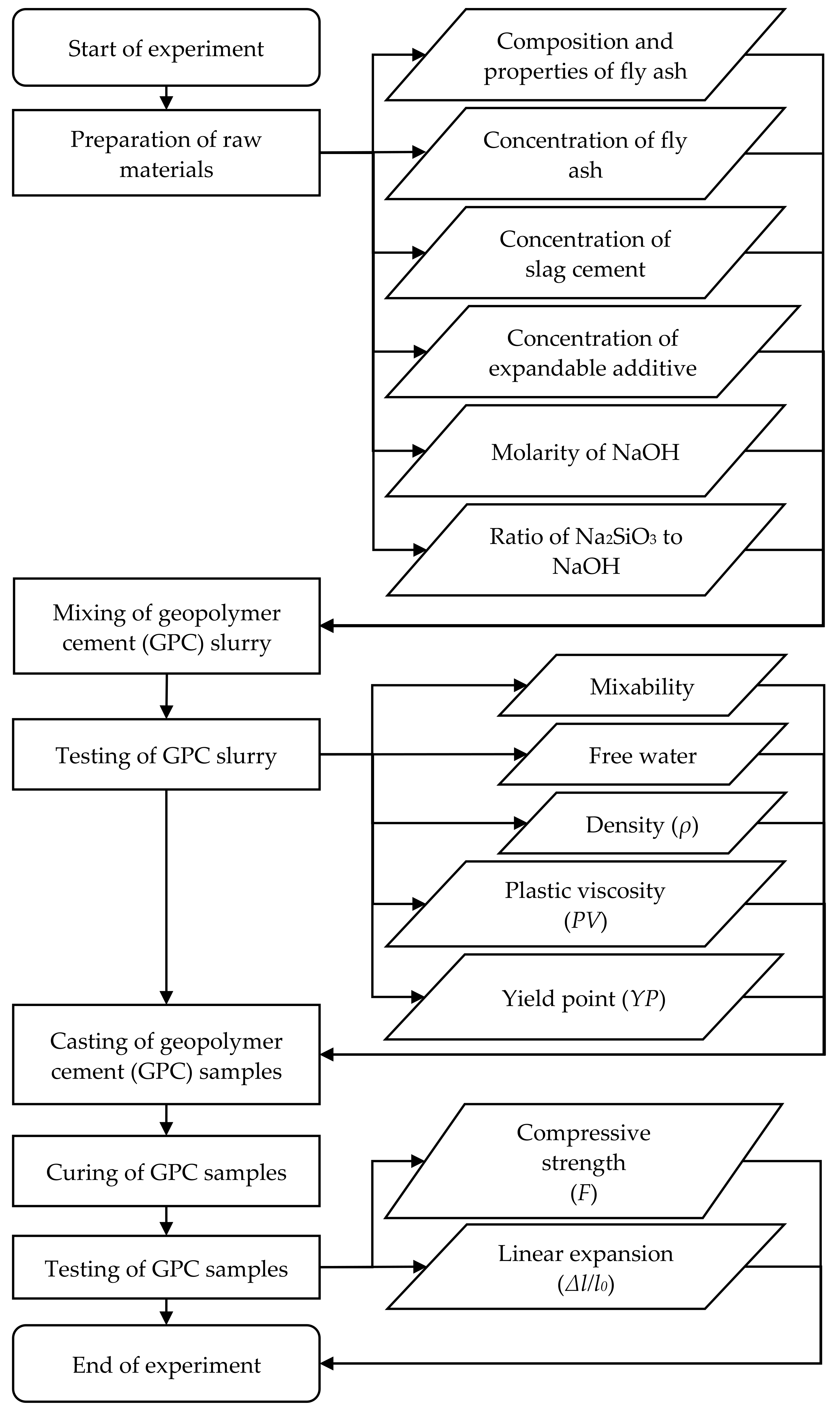
2. Materials and Methods

2.1. Preparation of Geopolymer Cement (GPC) Samples

GPC samples were prepared by using fly ash as the aluminosilicate source. The fly ash was obtained from the Tanjung Bin power plant in Johor, Malaysia, which is a 2100-MW coal-fired power plant [48] that implements denitrification technology. Figure 1 presents the particle size distributions of the fly ash sample obtained. According to the American Society for Testing Materials (ASTM), the fly ash can be classified as a Class F fly ash with a maximum calcium oxide (CaO) content of 6.72%, as per ASTM C618-19 [49]. The chemical composition of the fly ash, which was determined by using X-ray fluorescence of model S8 Tiger developed by Bruker (Billerica, MA, USA), is presented in Table 1. Micrographs of the fly ash were produced by using a scanning electron microscope of model Evo LS15 VPSEM developed by Zeiss (Jena, Germany), at magnifications of 1000× and 10,000×, as disclosed in Figure 2.
In order to enhance the strength of the cement to obtain the desired strength range for oil-well cementing, slag cement with a strength grade of 32.5 [50] was added to the mix as a strength enhancer, as implemented in previous studies [51,52,53], with a concentration of 10% of the weight of the fly ash and slag cement. Furthermore, R-additive, which is an elastomeric expandable additive that consists of styrene–butadiene rubber with a specific gravity of 0.945, was incorporated into the mix to induce expansion in the cement in an attempt to obstruct volumetric shrinkage. Four (4) mix formulations of the samples, namely R10, R15, R20 and R25, were specified, which were composed of, by weight of the mix, 65% of a solid blend that comprises fly ash, slag cement and R-additive, and 35% of an alkaline-activator solution that comprises 8M NaOH and Na2SiO3 with a Na2SiO3-to-NaOH molar ratio of 0.25. Concentration of the R-additive was increased from 10% to 15%, 20% and 25% by weight of the solid blend for formulations R10, R15, R20 and R25, respectively. Preliminary tests were conducted on trial mix designs prior to selecting the concentration range of R-additive, which was specified with the aim of attaining cement expansions that are acceptable to perform cementing for various well operations. Concentrations of the fly ash and slag cement, also by weight of the solid blend, were adjusted accordingly, as clarified in Table 2, with the percentage of solid blend fixed at 65% by weight of the mix.
Cement slurry with a volume of up to 600 mL was prepared for each mix. Mixing of slurry was performed by using a constant speed mixer of Model 3260, which was developed by Ametek Chandler Engineering (Tulsa, OK, USA), at an initial rotational speed of 4000 rpm for 15 s, which was subsequently increased to a final rotational speed of 12,000 rpm for 35 s after the solid constituents were completely poured into the mixer. Mixing was performed in accordance with API RP 10B-2 [54], which was also adopted to perform free-water and rheology tests on the slurry.
Slurry density is pivotal to modulate the pumping of slurry through the wellbore, where, during the operation, the equivalent circulating density (ECD) is adopted, which is the coalescence of the slurry density and annular pressure loss, as presented in Equation (2). In the present research, the slurry density (ρ) of each sample was measured in g/cm3, using a pressurized mud balance.
E C D = P a n n u l a r × 100 9.81 × T V D + ρ  
where ECD is the equivalent circulating density measured in kg/m3, Pannular is the annular pressure loss measured in kg/m2, TVD is the true vertical depth in m and ρ is the slurry density in kg/m3.
The free-water test was conducted by pouring the slurry into a 250-mL measuring cylinder and then leaving the slurry undisturbed for two (2) hours. Subsequently, the water that was present on top of the cement was collected to determine the amount of free water.
Rheological properties of the slurry were measured using an atmospheric rheometer of Model 35 manufactured by Fann Instrument Company (Houston, TX, USA). Kinematic viscosity (v) was recorded at rotational speeds of 100 and 300 rpm, and averages of five readings were taken for each rotational speed to calculate plastic viscosity (PV) and yield point (YP), as per Equations (3) and (4).
P V = v 300 v 100 × 1.5
Y P = v 300 P V
where PV is the plastic viscosity measured in cP; YP is the yield point measured in N/m2; and v 100 and v 300 are the kinematic viscosities at 100 and 300 rpm, respectively, measured in cP.

2.2. Measurement of Compressive Strength and Linear Expansion of GPC Samples

Cube samples of GPC with dimensions of 50 mm × 50 mm × 50 mm for each mix formulation were casted and cured in a water bath at 60 °C and atmospheric pressure, and a curing chamber at 90 °C and 3000 psi, which is approximately 20.68 MPa. Measurements of compressive strength and linear expansion were performed on the samples, which were cured for 1 day, 14 days, 30 days and 60 days. Measurement of compressive strength was conducted in accordance with API SPEC 10A [5], using a digital compressive strength tester of Model 4207D manufactured by Ametek Chandler Engineering (Tulsa, OK, USA). The compressive strength (F) of the samples was determined based on Equation (5).
F = P A  
where F is the compressive strength measured in psi, P is the compressive load at the point of failure measured in lbf and A is the cross-sectional surface area of the sample measured in inch2.
Measurement of linear expansion was performed based on the procedure described in API RP10B-5 [55], using an expansion cell based on Equation (6). The slurry was subjected to conditioning for 30 min and then poured into the expansion cell. The distance between two steel balls of the cell before expansion was recorded as the initial length (Li). Subsequently, the cell was placed into the water bath that was preheated to 60 °C and cured for a predetermined curing time. After curing, the cell was removed from the water bath, and the distance between the two steel balls after expansion was recorded as the final length (Lf) [17].
Δ l l 0 = L f L i × 0.358 L i × 100   %  
where ∆l/l0 is the linear expansion measured by percentage, Lf is the final length measured in mm and Li is the initial length measured in mm.
The process flow of the research methodology employed in the present study is illustrated in Figure 3.

3. Results and Discussion

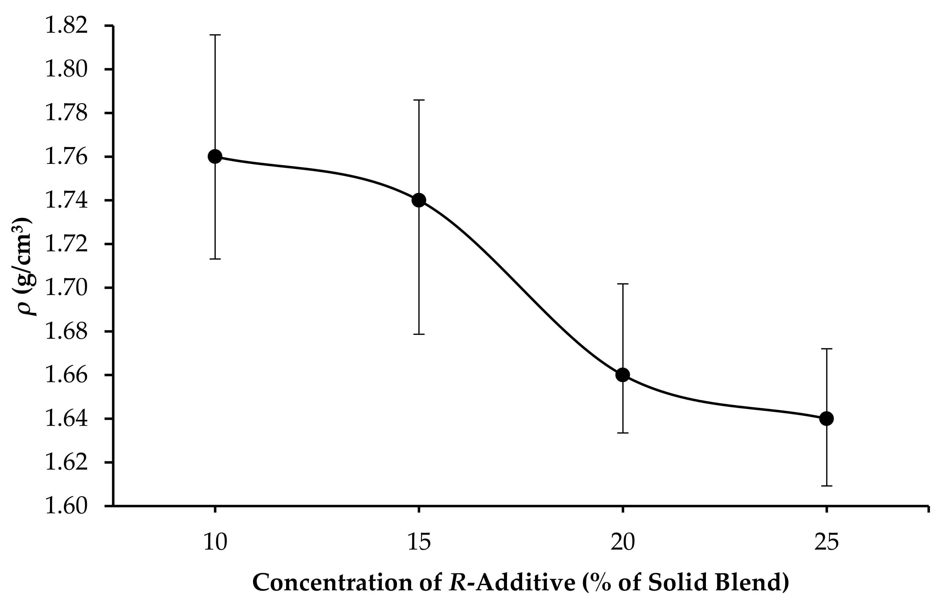
3.1. Mixability, Amount of Free Water and Density of GPC Slurry (ρ)

All formulations exhibited stability during mixing; the mixability and homogeneity were adequate; and the amount of free water collected was zero. Measurements of ρ revealed that the increase in concentration of R-additive from 10%, to 15%, 20% and 25% led to the reduction in slurry density from 1.76 to 1.74 g/cm3 and from 1.66 and 1.64 g/cm3, respectively, as shown in Figure 4. The rate of decline in ρ was the highest when the concentration of R-additive was increased from 15% to 20%, where ρ was reduced from 1.74 to 1.66 g/cm3.

3.2. Rheological Properties of GPC Slurry

The results reveal that the increase in the concentration of R-additive has led to the increase in rheological properties of the slurry, PV and YP. As shown in Figure 5, as the concentration of R-additive was raised from 10% to 15%, 20% and 25%, PV increased from 48 cP to 74, 83 and 104 cP, respectively. In view of the difficulties experienced during the pumping of slurry with PV that exceeds 100 cP through the wellbore, as elaborated by Igbani et al. [56] and Zahid et al. [57], the addition of R-additive at concentrations of not more than 20% is recommended. In parallel with the impact on PV, as presented in Figure 6, as the concentration of R-additive was raised from 10% to 15%, 20% and 25%, YP also increased from 3.8 N/m2 to 6.7, 10.1 and 12.3 N/m2, respectively. The increase in PV and YP with respect to the increase in concentration of R-additive is in agreement with the findings of Richhariya et al. [21], which employed dual-coated polyacrylamide (DPAM) as the additive, where it was deduced that the higher PV was obtained as a result of the gelation characteristics of the slurry, and the concentration of DPAM of 16% resulted in optimal rheological characteristics, as further additions of DPAM beyond 16% did not exhibit further variations of PV.

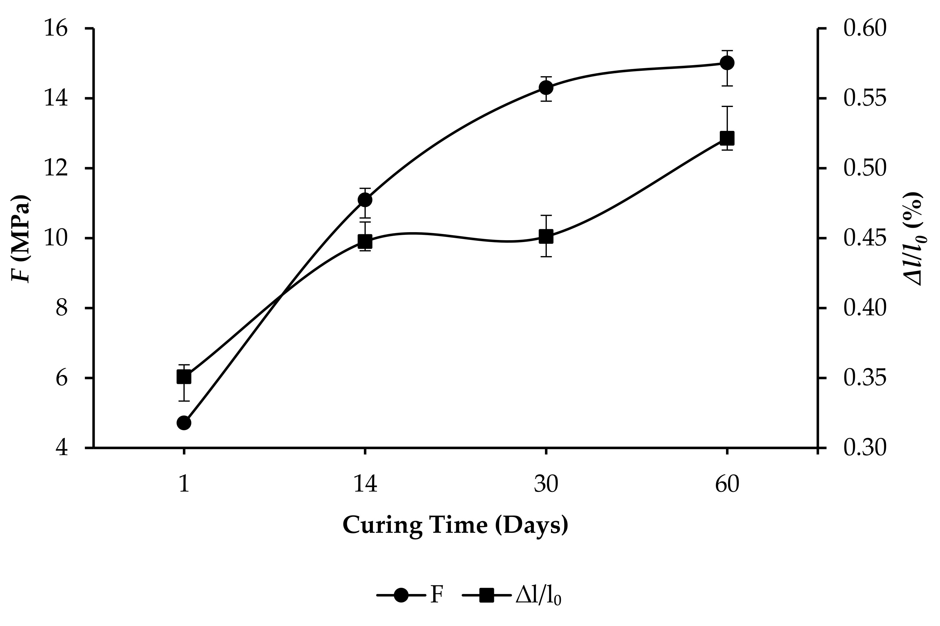
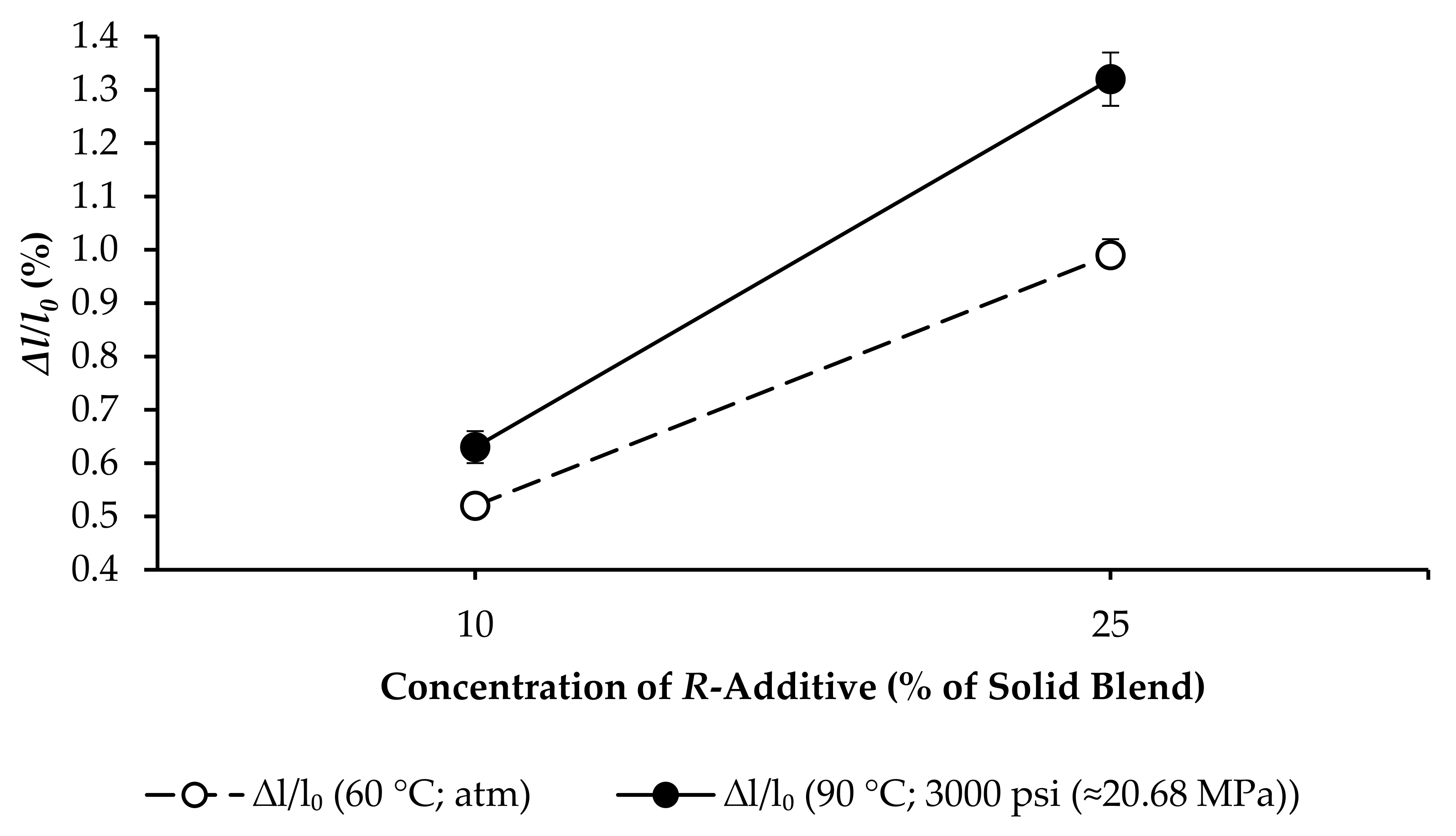
3.3. Compressive Strength and Linear Expansion of GPC Samples

In essence, the findings indicate that, as the curing time was extended, F and ∆l/l0 increased with gradients that vary from the curing times of 1 day to 14, 30 and 60 days. For GPC samples that were cured at 60 °C, at atmospheric pressure, the highest F of 15.01 MPa was obtained by R10, while the highest ∆l/l0 of 0.9985% was obtained by R25.
As the curing time increased from 1 day to 60 days, F and ∆l/l0 of each formulation increased as follows:
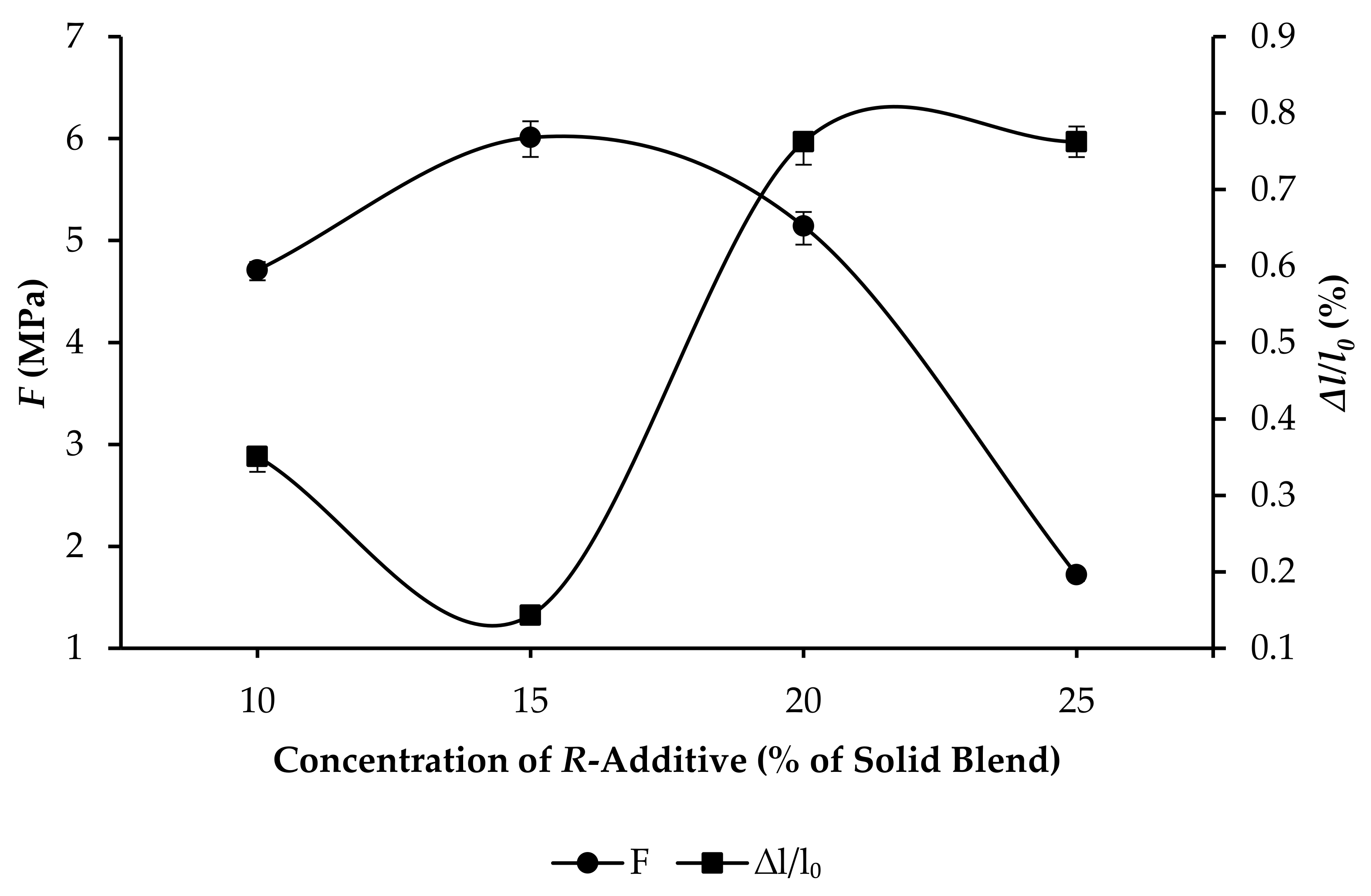
  • R10: F increased from 4.71 to 15.01 MPa, and ∆l/l0 increased from 0.3508% to 0.5213%, as per Figure 7.
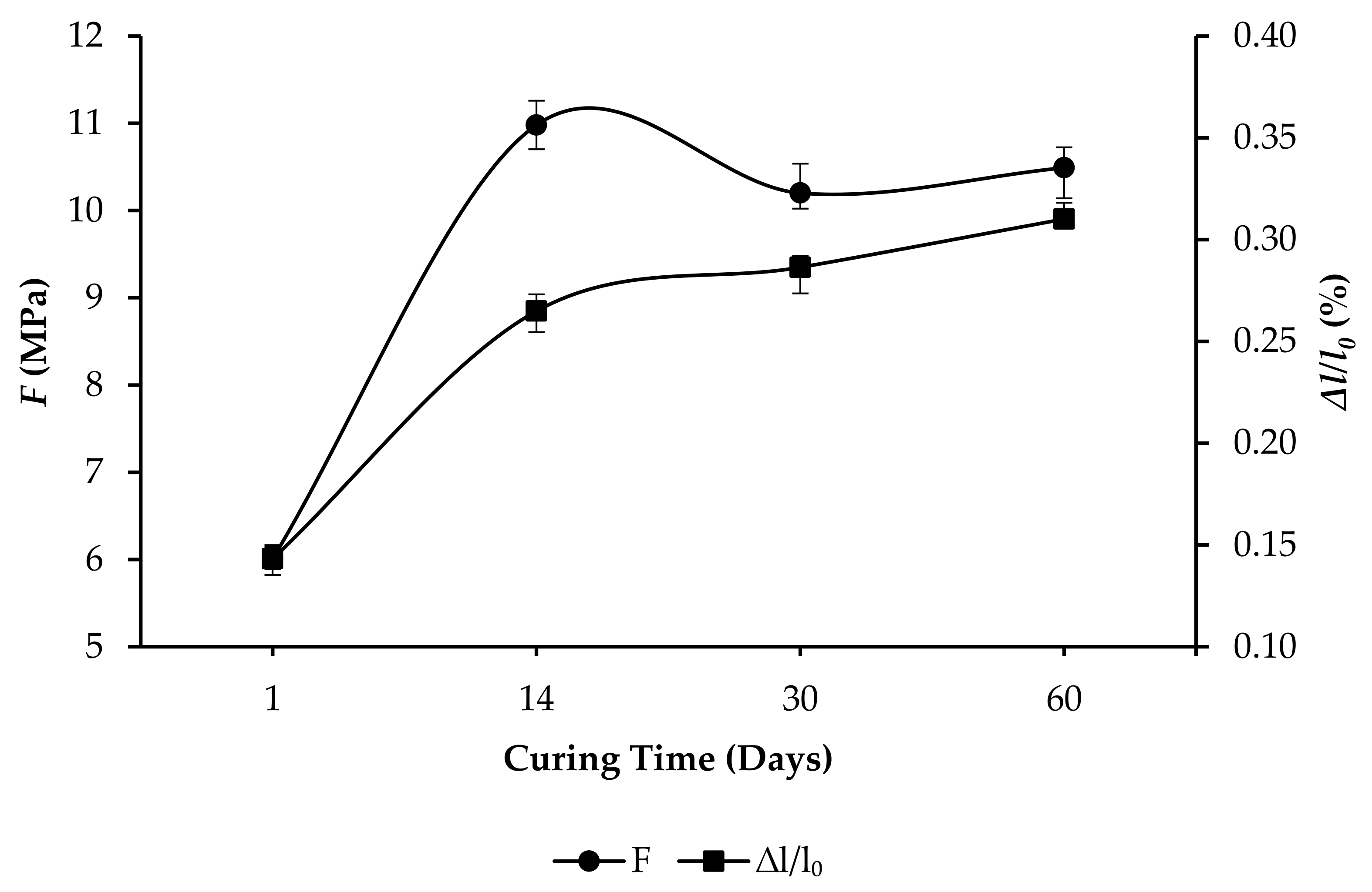
  • R15: F increased from 6.01 to 10.49 MPa, and ∆l/l0 increased from 0.1432% to 0.3101%, as per Figure 8.
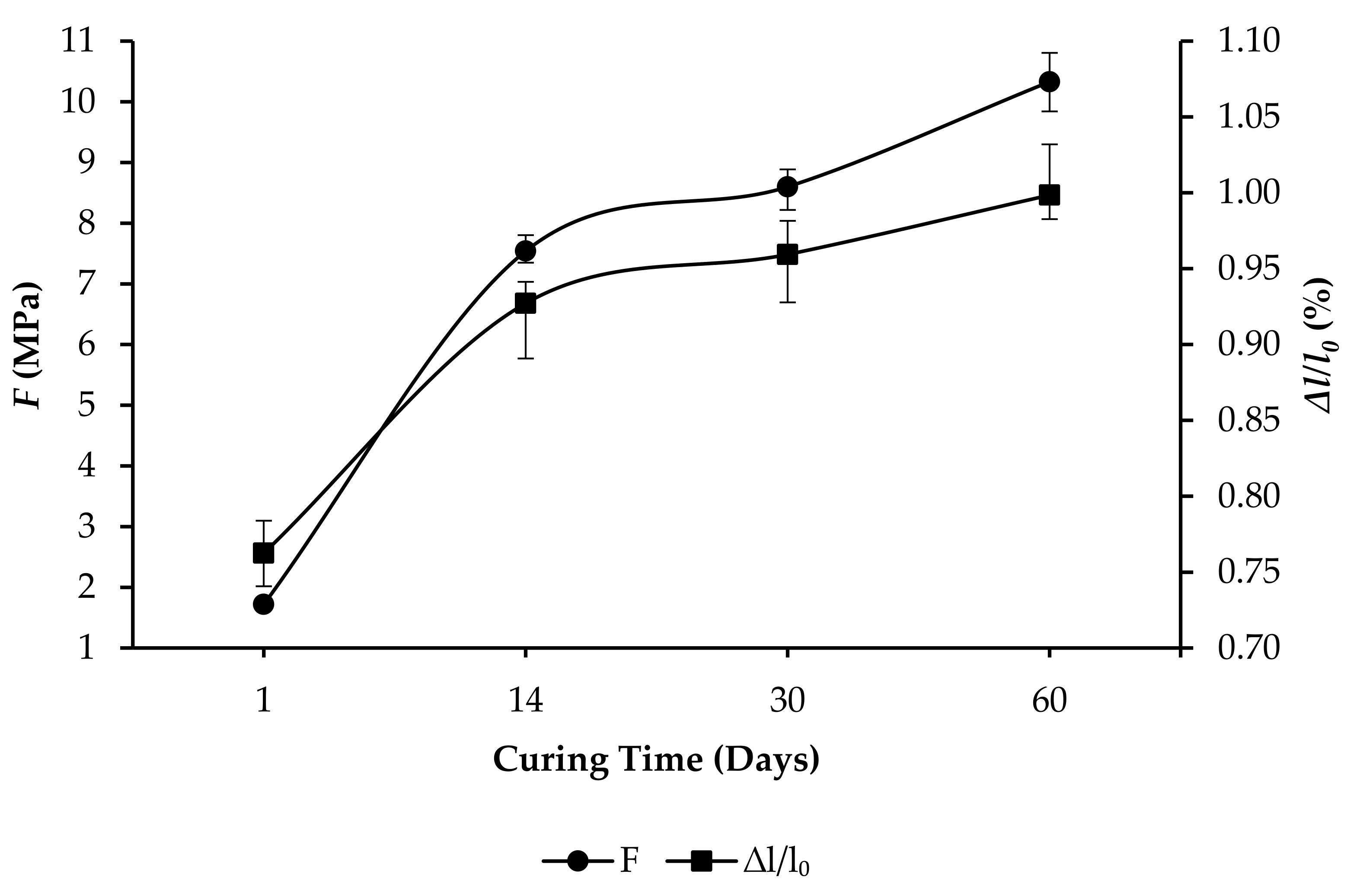
  • R20: F increased from 5.14 to 10.82 MPa, and ∆l/l0 increased from 0.7625% to 0.9903%, as per Figure 9.
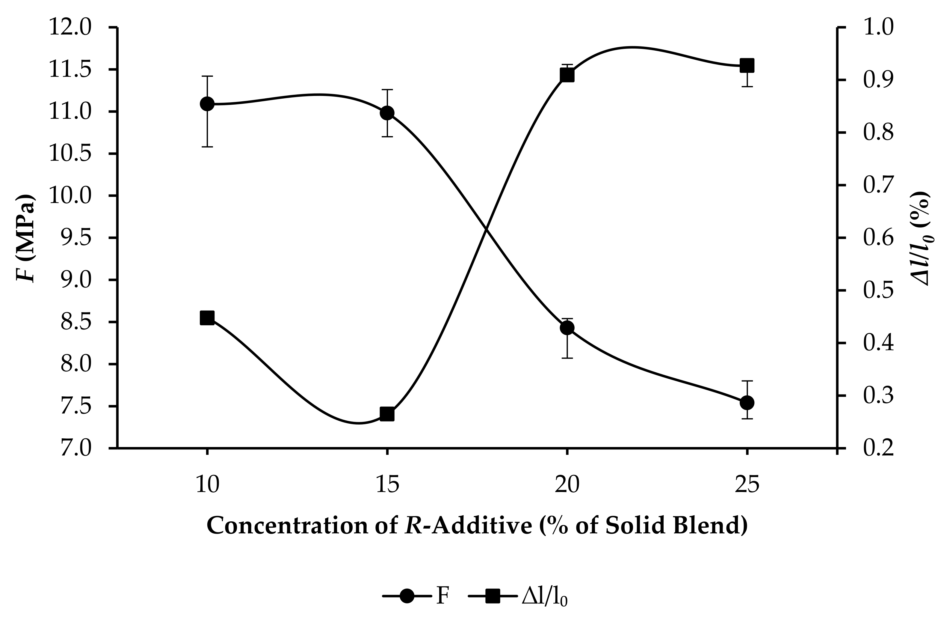
  • R25: F increased from 1.72 to 10.33 MPa, and ∆l/l0 increased from 0.7625% to 0.9985%, as per Figure 10.
The impacts of increasing the concentration of R-additive on F and ∆l/l0 are elucidated in Figure 11, Figure 12, Figure 13 and Figure 14 for samples that were cured for 1, 14, 30 and 60 days, respectively. Principally, as the concentration of R-additive was raised, F decreased with gradients that vary from the concentrations of R-additive of 10% to 15%, 20% and 25%. When the concentration of R-additive was increased from 10% to 15%, F increased for samples that were cured for 1 day, as shown in Figure 11; exhibited a trivial change for samples that were cured for 14 days, as shown in Figure 12; and, conversely, declined with a high gradient for samples that were cured for 30 and 60 days, as shown in Figure 12 and Figure 13, respectively. The findings are in agreement with Lee et al. [46] and Ekinci et al. [47], who highlighted that styrene–butadiene lowers the pH of the alkaline-activator solution and, in consequence, that of the geopolymer matrix, thus impeding the development of compressive strength. Accordingly, the addition of styrene–butadiene at higher concentrations led to further reduction in the pH of the geopolymer matrix and, as a consequence, further reduction in the compressive strength. Furthermore, Ekinci et al. [47] suggested that styrene–butadiene hinders the reaction between the raw material and alkaline-activator solution as it covers the interfaces of the raw material. Moreover, the addition of R-additive as an expandable additive led to the increase in bulk volume of the internal cement as explained in Baumgarte et al. [58]. Furthermore, based on Sofi [59], it can be added that higher concentrations of R-additive resulted in further reduction of F by virtue of the reduction in density. R-additive is an oil-swellable particle, and hence, as explained in Barlet-Gouédard et al. [60], it can counteract the formation of cracks, as it swells upon contact with oil; this can potentially address any issues associated with the formation of micro-annulus and micro-cracks that adversely enable formation fluids to flow through.
On the other hand, results reveal that, as the concentration of R-additive was raised from 10% to 15%, ∆l/l0 decreased. Subsequently, as the concentration of R-additive was raised further from 15% to 20%, ∆l/l0 increased with a higher gradient as compared to the prior decline in ∆l/l0. Subsequent change in ∆l/l0, owing to the further addition of R-additive from 20% to 25%, is inconsequential. Abd Rahman et al. [17] highlighted that, in contrast to OPC, GPC can expand by itself when exposed to water, even without the presence of expandable additives. The findings of Abd Rahman et al. [17] revealed that the amount of expansion of geopolymer cement was approximately 2.5 times higher than that of OPC at all curing durations. According to their findings, Abd Rahman et al. [17] suggested that the addition of expandable additives in geopolymer binders that are of the same types as those that are commercially available for OPC are compatible. Hence, in view of the findings of Abd Rahman et al. [17], the present study suggests the adoption of GPC coupled with the addition of an optimum concentration of expandable additives to further increase ∆l/l0.
The effects of curing time on F and ∆l/l0 of GPC samples with R10 and R25 formulations that were cured at 90 °C and 3000 psi (≈20.68 MPa) are presented in Figure 15 and Figure 16, respectively. When the R10 formulation was adopted, as the curing time increased from 1 day to 14, 30 and 60 days, F increased from 3.77 MPa to 11.69, 14.47 and 14.62 MPa, while ∆l/l0 increased from 0.04% to 0.10%, 0.45% and 0.63%, respectively. On the other hand, when the R25 formulation was adopted, F increased from 2.90 MPa to 8.79, 9.53 and 9.61 MPa, while ∆l/l0 increased from 0.19% to 0.21%, 1.17% and 1.32%, respectively. The profiles of F reveal that the increase in concentration of R-additive consistently led to lower values of F throughout the curing period, with an increasing difference between F of the R10 and R25 formulations as curing time increased.
As revealed in Figure 17, the increase in curing temperature and pressure from 60 °C and atmospheric pressure to 90 °C and 3000 psi (≈20.68 MPa), respectively, resulted in the reduction in F from 15.01 to 14.62 MPa and from 10.33 to 9.61 MPa when the concentrations of R-additive were 10% and 25%, respectively. The rise in temperature resulted in the loss of the initial properties of the R-additive within the cement matrix, which, as a consequence, led to the reduction in F of the GPC sample [61]. On the other hand, as revealed in Figure 18, an increase in ∆l/l0 from 0.52% to 0.63% and from 0.99% to 1.32% occurred due to the faster movement of molecules in the elastomer chain of the R-additive and an increase in its diffusion coefficient owing to the increase in temperature and pressure [62].
The formulations adopted in the present research, R10, R15, R20 and R25, fulfilled the requirements of the oil and gas industry and are aligned with the recommendations of Abbas et al. [63], Eric et al. [19], Mao et al. [64] and Richhariya et al. [21]. Multiple trial mixes were designed and tested prior to selecting the formulations to fulfill the specification requirements of API. Failure modes of the samples subjected to compressive strength tests are displayed in Figure 19, which shows that the samples were not completely crushed when the ultimate load was reached, and hence the samples were capable of resisting the load even after cracking. The compressive strengths of the formulations are acceptable for most well cementing operations, as they exceed 3.45 MPa [20].
As fly ash is a by-product of coal-fired power plants, its properties may vary according to, among others, age of the plant, ambient conditions and type and grade of coal employed. Accordingly, fly ash produced from different plants or batches of the same plant possesses inconsistent properties, hence presenting a limitation to the research. In the present study, screening was conducted on fly-ash samples collected from four different power plants in Malaysia that were selected based on the availability of samples, supply-chain management and approval from the Department of Environment of Malaysia for the supply prior to selecting the fly ash that was employed to produce the GPC samples. In addition to compliance to requirements for classification as a Class F fly ash as per ASTM C618-19 [49], the selection of the fly ash was determined with the aim of minimizing CaO content by virtue of its potential for resistance to CO2 when exposed to the high-CO2 environment of the oil and gas reservoir.

4. Conclusions

The present study aimed to investigate the effect of an expandable additive on the compressive strength and linear expansion of GPC, which is an alternative to OPC, for oil-well cementing. Fly-ash-based strength-enhanced GPC samples, with the addition of slag cement as the strength enhancer, were prepared by using different concentrations of R-additive and cured at 60 °C and atmospheric pressure. Mixability, amount of free water and slurry density were studied, and the effects of the concentration of R-additive on the compressive strength and linear expansion of the samples were analyzed. All formulations exhibited stability during mixing, mixability and homogeneity were adequate and the amount of free water collected was zero. An increase in the concentration of R-additive from 10% to 25% led to the reduction in the slurry density from 1.76 to 1.64 g/cm3 and an increase in the rheological properties of the slurry, where PV increased from 48 to 104 cP and YP also increased from 3.8 to 12.3 N/m2. An addition of R-additive at a concentration of 20% is recommended for optimization of the rheological properties. As the curing time was extended, F and ∆l/l0 increased with varying gradients. When cured at 60 °C and at atmospheric pressure, the highest F of 15.01 MPa was obtained when the concentration of R-additive was 10%, while the highest ∆l/l0 of 0.9985% was obtained when the concentration of R-additive was 25%. An increase in the curing temperature and pressure to 90 °C and 3000 psi (≈20.68 MPa) resulted in the reduction in F from 15.01 to 14.62 MPa and from 10.33 to 9.61 MPa, and the increase in ∆l/l0 from 0.52% to 0.63% and from 0.99% to 1.32%, when the concentrations of R-additive were 10% and 25%, respectively. The formulations adopted in the present research, which contain R-additive at concentrations ranging from 10% to 25%, fulfilled the requirements of the oil and gas industry.
Future research on the effect of adding elastomeric expandable additives to GPC to address volumetric shrinkage concerns in oil-well cementing can be augmented by performing an extensive study on the fluid flow for a wider and higher temperature range with cement qualification tests. In addition, the effect of downhole pressure can also be included in the investigations to assure that GPC can be adopted for a wide range of oil-well types.
Furthermore, in view of the inconsistent properties that fly ash produced from different plants or batches in the same plant, the development of pretreatment methods to standardize the quality of fly ash is recommended to facilitate the generation of findings that are consistent and reliable for future research that may employ fly ash from various sources.

Author Contributions

Conceptualization, S.H.A.R.; methodology, Y.A.S.; software, S.H.A.R.; validation, L.H.S.; formal analysis, N.N.Z.; investigation, N.H.; resources, M.F.H.; data curation, A.I.A.H.; writing—original draft preparation, S.A.F.; writing—review and editing, S.H.A.R.; visualization, L.H.S.; supervision, N.S.; project administration, Y.A.S.; funding acquisition, N.S. All authors have read and agreed to the published version of the manuscript.

Funding

This research was funded by PETRONAS Research Sdn. Bhd., Malaysia, via Project Cost Centre 015MD0-064, as administered by the Research Management Centre of Universiti Teknologi PETRONAS, Malaysia, and the Project Cost Centre E.025.GST.02019.003, as per the record of PETRONAS Research Sdn. Bhd.

Institutional Review Board Statement

Not applicable.

Informed Consent Statement

Not applicable.

Data Availability Statement

The data that support the findings of this study are available from PETRONAS Research Sdn. Bhd. Restrictions apply to the availability of these data, which were used under license for this study. Data are available from the corresponding author, S.H.A.R., with the permission of PETRONAS Research Sdn. Bhd.

Acknowledgments

The authors are thankful to the technologists of Universiti Teknologi PETRONAS and PETRONAS Research Sdn. Bhd. for the commitment and support to carry out various activities related to the experimental work in the laboratory.

Conflicts of Interest

The authors declare no conflict of interest.

Nomenclature

Abbreviations
APIAmerican Petroleum Institute
ASTMAmerican Society for Testing Materials
atmatmospheric pressure
DPAMdual-coated polyacrylamide
GPCgeopolymer cement
OPCordinary Portland cement
R-additiveelastomeric expandable additive used in the present study
SCPsustained casing pressure
Chemical Formulae
Al2Ca6H12O24S3ettringite
Al2O3aluminum oxide
Al–O–Sipolysialate
Al–O–Si–Sipolysialate siloxo
Al–O–Si–Si–Sipolysialate disiloxo
CaAl2O4calcium aluminate
CaCO3calcium carbonate
CaOcalcium oxide
CaSO4calcium sulfate
Ca2+calcium cation
Clchlorine
CO2carbon dioxide
C-S-Hcalcium-silicate-hydrate
Fe2O3iron (III) oxide
H2CO3carbonic acid
K2Opotassium oxide
K+potassium cation
MgOmagnesium oxide
NaOHsodium hydroxide
Na2Osodium oxide
Na2SiO3sodium silicate
Na+sodium cation
SiO2silicon dioxide
SO3sulfur trioxide
TiO2titanium (IV) Oxide
Notations
Across-sectional surface area of the sample
ECDequivalent circulating density
Fcompressive strength
Lffinal length as measured using the expansion cell
Liinitial length as measured using the expansion cell
Malkali cation
ndegree of polycondensation
Pcompressive load at the point of failure
Pannularannular pressure loss
PVplastic viscosity
TVDtrue vertical depth
v kinematic viscosity
v 100 kinematic viscosity at 100 rpm
v 300 kinematic viscosity at 300 rpm
YPyield point
l/l0linear expansion
ρ slurry density

References

  1. Abd Rahman, S.H.; Zulkarnain, N.N.; Shafiq, N. Experimental study and design of experiment using statistical analysis for the development of geopolymer matrix for oil-well cementing for enhancing the integrity. Crystals 2021, 11, 139. [Google Scholar] [CrossRef]
  2. Zulkarnain, N.N.; Farhan, S.A.; Sazali, Y.A.; Shafiq, N.; Abd Rahman, S.H.; Abd Hamid, A.I.; Habarudin, M.F. Reducing the waiting-on-cement time of geopolymer well cement using calcium chloride (CaCl2) as the accelerator: Analysis of the compressive strength and acoustic impedance for well logging. Sustainability 2021, 13, 6128. [Google Scholar] [CrossRef]
  3. Bu, Y.; Du, J.; Guo, S.; Liu, H.; Huang, C. Properties of oil well cement with high dosage of metakaolin. Constr. Build. Mater. 2016, 112, 39–48. [Google Scholar] [CrossRef]
  4. Khalifeh, M.; Saasen, A.; Hodne, H.; Godøy, R.; Vrålstad, T. Geopolymers as an Alternative for Oil Well Cementing Applications: A Review of Advantages and Concerns. In Proceedings of the 36th International Conference on Ocean, Offshore and Arctic Engineering, Trondheim, Norway, 25–30 June 2017; The American Society of Mechanical Engineers: New York, NY, USA, 2017. [Google Scholar] [CrossRef]
  5. API SPEC 10A; Cements and Materials for Well Cementing. American Petroleum Institute (API): Washington, DC, USA, 2019. Available online: https://standards.globalspec.com/std/14208303/api-spec-10a (accessed on 30 September 2021).
  6. Nasvi, M.C.M.; Ranjith, P.G.; Sanjayan, J. Comparison of Mechanical Behaviors of Geopolymer and Class G Cement as Well Cement at Different Curing Temperatures for Geological Sequestration of Carbon Dioxide. In Proceedings of the 46th U.S. Rock Mechanics/Geomechanics Symposium, Chicago, IL, USA, 24–27 June 2012; American Rock Mechanics Association: Alexandria, VA, USA, 2012. ARMA-2012-232. [Google Scholar]
  7. Barlet-Gouédard, V.; Rimmelé, G.; Goffé, B.; Porcherie, O. Well technologies for CO2 geological storage: CO2-resistant cement. Oil Gas Sci. Technol.-Rev. IFP 2007, 62, 325–334. [Google Scholar] [CrossRef]
  8. Liteanu, E.; Spiers, C.J.; Peach, C.J. Failure behaviour wellbore cement in the presence of water and supercritical CO2. Energy Procedia 2009, 1, 3553–3560. [Google Scholar] [CrossRef] [Green Version]
  9. Salehi, S.; Khattak, M.J.; Ali, N.; Ezeakacha, C.; Saleh, F.K. Study and use of geopolymer mixtures for oil and gas well cementing applications. J. Energy Resour. Technol. 2018, 140, 012908. [Google Scholar] [CrossRef]
  10. Salehi, S.; Ezeakacha, C.P.; Khattak, M.J. Geopolymer Cements: How Can You Plug and Abandon a Well with New Class of Cheap Efficient Sealing Materials. In Proceedings of the SPE Oklahoma City Oil and Gas Symposium, Oklahoma City, OK, USA, 27–31 March 2017; Society of Petroleum Engineers: Richardson, TX, USA, 2017. [Google Scholar] [CrossRef]
  11. Vrålstad, T.; Saasen, A.; Fjær, E.; Øia, T.; Ytrehus, J.D.; Khalifeh, M. Plug & abandonment of offshore wells: Ensuring long-term well integrity and cost-efficiency. J. Pet. Sci. Eng. 2018, 173, 478–491. [Google Scholar] [CrossRef]
  12. Bois, A.-P.; Garnier, A.; Galdiolo, G.; Laudet, J.-B. Use of a mechanistic model to forecast cement-sheath integrity. SPE Drill. Complet. 2012, 27, 303–314. [Google Scholar] [CrossRef]
  13. Santra, A.K.; Reddy, B.R.; Liang, F.; Fitzgerald, R. Reaction of CO2 with Portland Cement at Downhole Conditions and the Role of Pozzolanic Supplements. In Proceedings of the SPE International Symposium on Oilfield Chemistry, The Woodlands, TX, USA, 20–22 April 2009; Society of Petroleum Engineers: Richardson, TX, USA, 2009. [Google Scholar] [CrossRef]
  14. Reddy, B.R.; Xu, Y.; Ravi, K.; Gray, D.W.; Pattillo, P. Cement shrinkage measurement in oilwell cementing—a comparative study of laboratory methods and procedures. SPE Drill. Complet. 2009, 24, 104–114. [Google Scholar] [CrossRef]
  15. Kosmatka, S.H.; Wilson, M.L. Design and Control of Concrete Mixtures: The Guide to Applications, Methods, and Materials, 15th ed.; Portland Cement Association: Skokie, IL, USA, 2011. [Google Scholar]
  16. Nasvi, M.C.M.; Ranjith, P.G.; Sanjayan, J.; Bui, H. Effect of temperature on permeability of geopolymer: A primary well sealant for carbon capture and storage wells. Fuel 2014, 117, 354–363. [Google Scholar] [CrossRef]
  17. Abd Rahman, S.H.; Irawan, S.; Shafiq, N.; Suppiah, R.R. Investigating the expansion characteristics of geopolymer cement samples in a water bath and compared with the expansion of ASTM Class-G cement. Heliyon 2020, 6, e03478. [Google Scholar] [CrossRef] [Green Version]
  18. Nagral, M.R.; Ostwal, T.; Chitawadagi, M.V. Effect of curing temperature and curing hours on the properties of geo-polymer concrete. Int. J. Comput. Eng. Res. 2014, 4, 1–11. [Google Scholar]
  19. Eric, B.; Joel, F.; Grace, O. Oil well cement additives: A review of the common types. Oil Gas Res. 2016, 2, 112. [Google Scholar] [CrossRef]
  20. Ridha, S.; Abd Hamid, A.I.; Abdul Halim, A.H.; Zamzuri, N.A. Elasticity and expansion test performance of geopolymer as oil well cement. IOP Conf. Ser. Earth Environ. Sci. 2018, 140, 012147. [Google Scholar] [CrossRef] [Green Version]
  21. Richhariya, G.; Dora, D.T.K.; Parmar, K.R.; Pant, K.K.; Singhal, N.; Lal, K.; Kundu, P.P. Development of self-healing cement slurry through the incorporation of dual-encapsulated polyacrylamide for the prevention of water ingress in oil well. Materials 2020, 13, 2921. [Google Scholar] [CrossRef]
  22. Duguid, A.; Scherer, G.W. Degradation of oilwell cement due to exposure to carbonated brine. Int. J. Greenh. Gas Control 2010, 4, 546–560. [Google Scholar] [CrossRef]
  23. Bourgoyne, A.T.; Scott, S.L.; Regg, J.B. Sustained Casing Pressure in Offshore Producing Wells. In Proceedings of the Offshore Technology Conference, Houston, TX, USA, 3–6 May 1999. [Google Scholar] [CrossRef]
  24. Farkas, R.F.; England, K.W.; Roy, M.L.; Dickinson, M.; Samuel, M.; Hart, R.E. New Cementing Technology Cures 40-Year-Old Squeeze Problems. In Proceedings of the SPE Annual Technical Conference and Exhibition, Houston, TX, USA, 3–6 October 1999; Society of Petroleum Engineers: Richardson, TX, USA, 1999. [Google Scholar] [CrossRef]
  25. Merlini, M.; Artioli, G.; Cerulli, T.; Cella, F.; Bravo, A. Tricalcium aluminate hydration in additivated systems. a crystallographic study by SR-XRPD. Cem. Concr. Res. 2008, 38, 477–486. [Google Scholar] [CrossRef]
  26. Chenevert, M.E.; Shrestha, B.K. Chemical shrinkage properties of oilfield cements. SPE Drill. Eng. 1991, 6, 37–43. [Google Scholar] [CrossRef]
  27. Kiran, R.; Teodoriu, C.; Dadmohammadi, Y.; Nygaard, R.; Wood, D.; Mokhtari, M.; Salehi, S. Identification and evaluation of well integrity and causes of failure of well integrity barriers (a review). J. Nat. Gas Sci. Eng. 2017, 45, 511–526. [Google Scholar] [CrossRef]
  28. Davidovits, J. Geopolymer Chemistry & Applications, 3rd ed.; Institut Géopolymère: Saint-Quentin, France, 2011. [Google Scholar]
  29. Kong, D.L.Y.; Sanjayan, J.G.; Sagoe-Crentsil, K. Comparative performance of geopolymers made with metakaolin and fly ash after exposure to elevated temperatures. Cem. Concr. Res. 2007, 37, 1583–1589. [Google Scholar] [CrossRef]
  30. Thokchom, S.; Ghosh, P.; Ghosh, S. Resistance of fly ash based geopolymer mortars in sulfuric acid. ARPN J. Eng. Appl. Sci. 2009, 4, 65–70. [Google Scholar]
  31. Palomo, A.; Grutzeck, M.W.; Blanco, M.T. Alkali-activated fly ashes: A cement for the future. Cem. Concr. Res. 1999, 29, 1323–1329. [Google Scholar] [CrossRef]
  32. Dimas, D.; Giannopoulou, I.; Panias, D. Polymerization in sodium silicate solutions: A fundamental process in geopolymerization technology. J. Mater. Sci. 2009, 44, 3719–3730. [Google Scholar] [CrossRef]
  33. Khalifeh, M.; Saasen, A.; Vrålstad, T. Potential Utilization of Geopolymers in Plug and Abandonment Operations. In Proceedings of the SPE Bergen One Day Seminar, Bergen, Norway, 2 April 2014; Society of Petroleum Engineers: Richardson, TX, USA, 2014. [Google Scholar] [CrossRef]
  34. Nasvi, M.M.C.; Gamage, R.P.; Jay, S. Geopolymer as well cement and the variation of its mechanical behavior with curing temperature. Greenh. Gas Sci. Technol. 2012, 2, 46–58. [Google Scholar] [CrossRef]
  35. Uehara, M. New concrete with low environmental load using the geopolymer method. Q. Rep. RTRI 2010, 51, 1–7. [Google Scholar] [CrossRef] [Green Version]
  36. Liu, X.; Aughenbaugh, K.; Nair, S.; Shuck, M.; van Oort, E. Solidification of Synthetic-Based Drilling Mud using Geopolymers. In Proceedings of the SPE Deepwater Drilling and Completions Conference, Galveston, TX, USA, 14–15 September 2016; Society of Petroleum Engineers: Richardson, TX, USA, 2016. [Google Scholar] [CrossRef]
  37. Khalifeh, M.; Hodne, H.; Saasen, A.; Integrity, O.; Eduok, E.I. Usability of Geopolymers for Oil Well Cementing Applications: Reaction Mechanisms, Pumpability, and Properties. In Proceedings of the SPE Asia Pacific Oil & Gas Conference and Exhibition, Perth, Australia, 25–27 October 2016; Society of Petroleum Engineers: Richardson, TX, USA, 2016. [Google Scholar] [CrossRef]
  38. Khalifeh, M.; Todorovic, J.; Vrålstad, T.; Saasen, A.; Hodne, H. Long-term durability of rock-based geopolymers aged at downhole conditions for oil well cementing operations. J. Sustain. Cem.-Based Mater. 2017, 6, 217–230. [Google Scholar] [CrossRef]
  39. Van Jaarsveld, J.G.S.; Van Deventer, J.S.J.; Lorenzen, L. The potential use of geopolymeric materials to immobilise toxic metals: Part I. Theory and applications. Miner. Eng. 1997, 10, 659–669. [Google Scholar] [CrossRef]
  40. Diaz, E.I.; Allouche, E.N. Recycling of Fly Ash into Geopolymer Concrete: Creation of a Database. In Proceedings of the 2010 IEEE Green Technologies Conference, Grapevine, TX, USA, 15–16 April 2010; Institute of Electrical and Electronics Engineers: Piscataway, NJ, USA, 2010; pp. 1–7. [Google Scholar] [CrossRef]
  41. Yang, Z.X.; Ha, N.R.; Jang, M.S.; Hwang, K.H. Geopolymer concrete fabricated by waste concrete sludge with silica fume. Mater. Sci. Forum. 2009, 620–622, 791–794. [Google Scholar] [CrossRef]
  42. Hewayde, E.; Nehdi, M.; Allouche, E.; Nakhla, G. Effect of geopolymer cement on microstructure, compressive strength and sulphuric acid resistance of concrete. Mag. Concr. Res. 2006, 58, 321–331. [Google Scholar] [CrossRef]
  43. Lloyd, N.; Rangan, B. Geopolymer Concrete with Fly Ash. In Proceedings of the Second International Conference on Sustainable Construction Materials and Technologies, Università Politecnica delle Marche, Ancona, Italy, 28–30 June 2010; University of Wisconsin-Milwaukee: Milwaukee, WI, USA, 2010; pp. 1493–1504. [Google Scholar]
  44. Majidi, B. Geopolymer technology, from fundamentals to advanced applications: A review. Mater. Technol. Adv. Perform. Mater. 2009, 24, 79–87. [Google Scholar] [CrossRef]
  45. Davidovits, J. Environmentally driven geopolymer applications. In Proceedings of the Geopolymer Conference, Melbourne, Australia, 28–29 October 2002; Institut Géopolymère: Saint-Quentin, France, 2002. [Google Scholar]
  46. Lee, N.K.; Kim, E.M.; Lee, H.K. Mechanical properties and setting characteristics of geopolymer mortar using styrene-butadiene (SB) latex. Constr. Build. Mater. 2016, 113, 264–272. [Google Scholar] [CrossRef]
  47. Ekinci, E.; Türkmen, I.; Kantarci, F.; Karakoç, M.B. The improvement of mechanical, physical and durability characteristics of volcanic tuff based geopolymer concrete by using nano silica, micro silica and styrene-butadiene latex additives at different ratios. Constr. Build. Mater. 2019, 201, 257–267. [Google Scholar] [CrossRef]
  48. Our Business: Power Plant and Water Desalination Plant Locations. Available online: https://www.malakoff.com.my/Our-Business/Power-Plant-and-Water-Desalination-Plant-Locations/ (accessed on 5 November 2021).
  49. ASTM C618–19; Standard Specification for Coal Fly Ash and Raw or Calcined Natural Pozzolan for Use in Concrete. ASTM International: West Conshohocken, PA, USA, 2019.
  50. GB 175-2007/XG3-2018; Common Portland Cement, Including Amendment 3. Code of China: Beijing, China, 2019.
  51. Yuhuan, B.; Rui, M.; Jiapei, D.; Shenglai, G.; Huajie, L.; Letian, Z. Utilization of metakaolin-based geopolymer as a mud-cake solidification agent to enhance the bonding strength of oil well cement–formation interface. R. Soc. Open Sci. 2020, 7, 191230. [Google Scholar] [CrossRef] [Green Version]
  52. Kallesten, B.; Kakay, S.; Gebremariam, K. Synthesis and characterization of fly ash and slag based geopolymer concrete. IOP Conf. Ser. Mater. Sci. Eng. 2019, 700, 012032. [Google Scholar] [CrossRef]
  53. Kanesan, D.; Ridha, S.; Rao, P. Formulation of geopolymer cement using mixture of slag and Class F fly ash for oil well cementing. IOP Conf. Ser. Mater. Sci. Eng. 2017, 201, 012014. [Google Scholar] [CrossRef] [Green Version]
  54. API RP 10B-2; Recommended Practice for Testing Well Cements. 2nd ed. American Petroleum Institute (API): Washington, DC, USA, 2019.
  55. API RP10B-5; Recommended Practice on Determination of Shrinkage and Expansion of Well Cement Formulations at Atmospheric Pressure. American Petroleum Institute (API): Washington, DC, USA, 2005.
  56. Igbani, S.; Appah, D.; Ogoni, H.A. The application of response surface methodology in Minitab 16, to identify the optimal, comfort, and adverse zones of compressive strength responses in ferrous oilwell cement sheath systems. Int. J. Eng. Mod. Technol. 2020, 6, 20–39. [Google Scholar]
  57. Zahid, M.; Shafiq, N.; Isa, M.H.; Gil, L. Statistical modeling and mix design optimization of fly ash based engineered geopolymer composite using response surface methodology. J. Clean. Prod. 2018, 194, 483–498. [Google Scholar] [CrossRef]
  58. Baumgarte, C.; Thiercelin, M.; Klaus, D. Case studies of expanding cement to prevent microannular formation. In Proceedings of the SPE Annual Technical Conference and Exhibition, Houston, TX, USA, 3–6 October 1999; Society of Petroleum Engineers: Richardson, TX, USA, 1999. [Google Scholar] [CrossRef]
  59. Sofi, A. Effect of waste tyre rubber on mechanical and durability properties of concrete—A review. Ain Shams Eng. J. 2018, 9, 2691–2700. [Google Scholar] [CrossRef]
  60. Barlet-Gouédard, V.; Rimmelé, G.; Porcherie, O.; Quisel, N.; Desroches, J. A solution against well cement degradation under CO2 geological storage environment. Int. J. Greenh. Gas Control 2009, 3, 206–216. [Google Scholar] [CrossRef]
  61. Powers, P.O.; Billmeyer, B.R. Swelling of synthetic rubbers in mineral oils. Effect of temperature and aniline point. Rubber Chem. Technol. 1945, 18, 452–459. [Google Scholar] [CrossRef]
  62. Shan, G.-R.; Xu, P.-Y.; Weng, Z.-X.; Huang, Z.-M. Oil-absorption function of physical crosslinking in the high-oil-absorption resins. J. Appl. Polym. Sci. 2003, 90, 3945–3950. [Google Scholar] [CrossRef]
  63. Abbas, G.; Irawan, S.; Kumar, S.; Elrayah, A.A.I. Improving oil well cement slurry performance using hydroxypropylmethylcellulose polymer. Adv. Mater. Res. 2013, 787, 222–227. [Google Scholar] [CrossRef]
  64. Mao, W.; Litina, C.; Al-Tabbaa, A. Development and application of novel sodium silicate microcapsule-based self-healing oil well cement. Materials 2020, 13, 456. [Google Scholar] [CrossRef] [Green Version]
Figure 1. Particle size distribution of the fly ash obtained from the Tanjung Bin power plant.
Applsci 12 01897 g001
Figure 2. Micrographs of the fly ash employed in the present study at magnifications of (a) 1000× and (b) 10,000×.
Applsci 12 01897 g002
Figure 3. Process flow of the research methodology employed in the present study.
Applsci 12 01897 g003
Figure 4. Density (ρ) of geopolymer cement (GPC) slurry at varying concentrations of elastomeric expandable additive (R-additive).
Applsci 12 01897 g004
Figure 5. Plastic viscosity (PV) of GPC slurry at varying concentrations of R-additive.
Applsci 12 01897 g005
Figure 6. Yield point (YP) of GPC slurry at varying concentrations of R-additive.
Applsci 12 01897 g006
Figure 7. Compressive strength (F) and linear expansion (∆l/l0), at varying curing times, of GPC samples with R10 formulation that were cured at 60 °C, at atmospheric pressure.
Applsci 12 01897 g007
Figure 8. F and ∆l/l0, at varying curing times, of GPC samples with R15 formulation that were cured at 60 °C, at atmospheric pressure.
Applsci 12 01897 g008
Figure 9. F and ∆l/l0, at varying curing times, of GPC samples with R20 formulation that were cured at 60 °C, at atmospheric pressure.
Applsci 12 01897 g009
Figure 10. F and ∆l/l0, at varying curing times, of GPC samples with R25 formulation that were cured at 60 °C, at atmospheric pressure.
Applsci 12 01897 g010
Figure 11. F and ∆l/l0, at varying concentrations of R-additive, of GPC samples that were cured at 60 °C, at atmospheric pressure, after 1 day of curing.
Applsci 12 01897 g011
Figure 12. F and ∆l/l0, at varying concentrations of R-additive, of GPC samples that were cured at 60 °C, at atmospheric pressure, after 14 days of curing.
Applsci 12 01897 g012
Figure 13. F and ∆l/l0, at varying concentrations of R-additive, of GPC samples that were cured at 60 °C, at atmospheric pressure, after 30 days of curing.
Applsci 12 01897 g013
Figure 14. F and ∆l/l0, at varying concentrations of R-additive, of GPC samples that were cured at 60 °C in atmospheric pressure after 60 days of curing.
Applsci 12 01897 g014
Figure 15. F, at varying curing times, of GPC samples that were cured at 90 °C and 3000 psi (≈20.68 MPa).
Applsci 12 01897 g015
Figure 16.l/l0, at varying curing times, of GPC samples that were cured at 90 °C and 3000 psi (≈20.68 MPa).
Applsci 12 01897 g016
Figure 17. F, at 10% and 25% concentrations of R-additive, of GPC samples after 60 days of curing.
Applsci 12 01897 g017
Figure 18.l/l0, at 10% and 25% concentrations of R-additive, of GPC samples after 60 days of curing.
Applsci 12 01897 g018
Figure 19. Failure mode of the samples subjected to compressive-strength tests.
Applsci 12 01897 g019
Table 1. Chemical composition of the fly ash employed in the present study.
Element/ParameterWeight (%)
Silicon Dioxide (SiO2)46.47
Aluminum Oxide (Al2O3)25.95
Iron (III) Oxide (Fe2O3)8.31
Calcium Oxide (CaO)6.88
Magnesium Oxide (MgO)4.95
Potassium Oxide (K2O)2.11
Sodium Oxide (Na2O)1.72
Titanium (IV) Oxide (TiO2)1.16
Sulfur Trioxide (SO3)0.63
Chlorine (Cl)<0.1
Moisture0.11
Loss of Ignition1.61
Table 2. Concentrations of each constituent of the solid blend for each mix formulation.
Mix FormulationConcentration (% of Solid Blend)
R-AdditiveFly AshSlag Cement
R101081.09.0
R151576.58.5
R202072.08.0
R252567.57.5
Publisher’s Note: MDPI stays neutral with regard to jurisdictional claims in published maps and institutional affiliations.

