1. Introduction
Hypersonic vehicles in near space fly over the speed of Mach five, which is five times the speed of sound [
1]. A bow shock is generated by friction between vehicle and atmosphere, which can result in a huge amount of heat. In such cases, the temperature of the area near the vehicle nose can be up to thousands of degrees Kelvins and air molecules can ionize and dissociate. The plasma sheath is formed as a result of the generation of numerous free electrons. The plasma sheath can shield communication signals and cause ‘blackout’ problems which are a serious threat to vehicle safety [
2]. The problem remains unsolved despite the enormous amount of research efforts have been made. Methods of minimizing communications blackout also are being explored. The most famous program is called Project RAM (radio attenuation measurements) and consisted of eight rocket flights (seven successful) from 1961 to 1970 [
3,
4]. The project was conducted at the NASA Langley Research Center to study, both theoretically and experimentally, the effects of the reentry plasma sheath upon reentry vehicle communications systems [
5,
6].
With the rapid development of terahertz (THz) technology and instruments, THz communication has been considered as a potential approach to communication blackout for its high frequency, which leads to better penetration [
7,
8]. The performances of antennae in idealized plasma layers have been researched. Electron density and the electron collision frequency have been revealed as the two most important plasma parameters that significantly affect antenna performance [
9,
10,
11]. On the other hand, some previous studies reveal that the parameters of the plasma sheaths depend on many factors, e.g., atmospheric conditions [
12], flight speed [
8], angle of attack [
13], and the shape of the vehicle [
14], in which case antenna performance is affected.
Vehicle shape is one of the most important parameters for the flight condition and directly determines the distribution of the plasma sheath. However, the impacts of vehicle shape on the radiation performance of antenna have only been roughly discussed in previous studies. Moreover, the antenna in the previous studies was a single antenna working in the HF-VHF band [
11]. EHF array antenna performance in plasma sheaths corresponding to different vehicle shapes are rarely investigated. A method of replacing an on-board single antenna with an array antenna and using beamforming technology has been proposed by researchers to mitigate the problem [
15]. Array antennae can provide a certain amount of gain to the communication link [
11]. In the present study, a 0.14 THz array antenna and plasma coupling models were established to obtain the detailed influence of vehicle shape on the antenna performance. The corresponding vehicle shapes are blunt-coned and sharp-coned. The antenna involved in the study operates at 0.14 THz, which is an ’atmospheric window’. Based on the results, suggestions of vehicle shape design to guarantee communication quality in hypersonic flight mission are proposed.
2. The Plasma Sheath and the THz Array Antenna
The models consist of two parts, the plasma sheath and the 0.14 THz array antenna. In order to investigate the impact of vehicle shape on onboard antenna performance, plasma flow fields corresponding to two common shapes are simulated. The two shapes are blunt-coned and sharp-coned.
2.1. The Plasma Sheaths Corresponding to Blunt-Coned Vehicle and Sharp-Coned Vehicles
The models were used to simulate the hypersonic flying process of blunt-coned vehicles and sharp-coned vehicles in the atmosphere. Since the air in the atmosphere can be considered as a compressible fluid, the finite volume method (FVM) [
16] was used to solve the hypersonic hydrodynamic models. In such a case, the plasma flow fields are obtained by numerically solving the models. Moreover, the model is reliable since the simulation results agree well with the RAM experiments results. This study uses the plasma sheath model to explore the antenna performance with different vehicle shapes, which is original and different from our previous works [
8,
12,
13,
16].
The size of the blunt-coned vehicle is the same as the reentry vehicle involved in the RAMs [
17]. The length and the bottom size of the sharp-coned vehicle are equal to that of the blunt-coned vehicle. The two vehicles are set to fly at the speed of 6550 m/s with a
attack angle. The flight altitude of the vehicles is 30 km. The mass density of the neutral atmosphere at this altitude is
kg/m
.
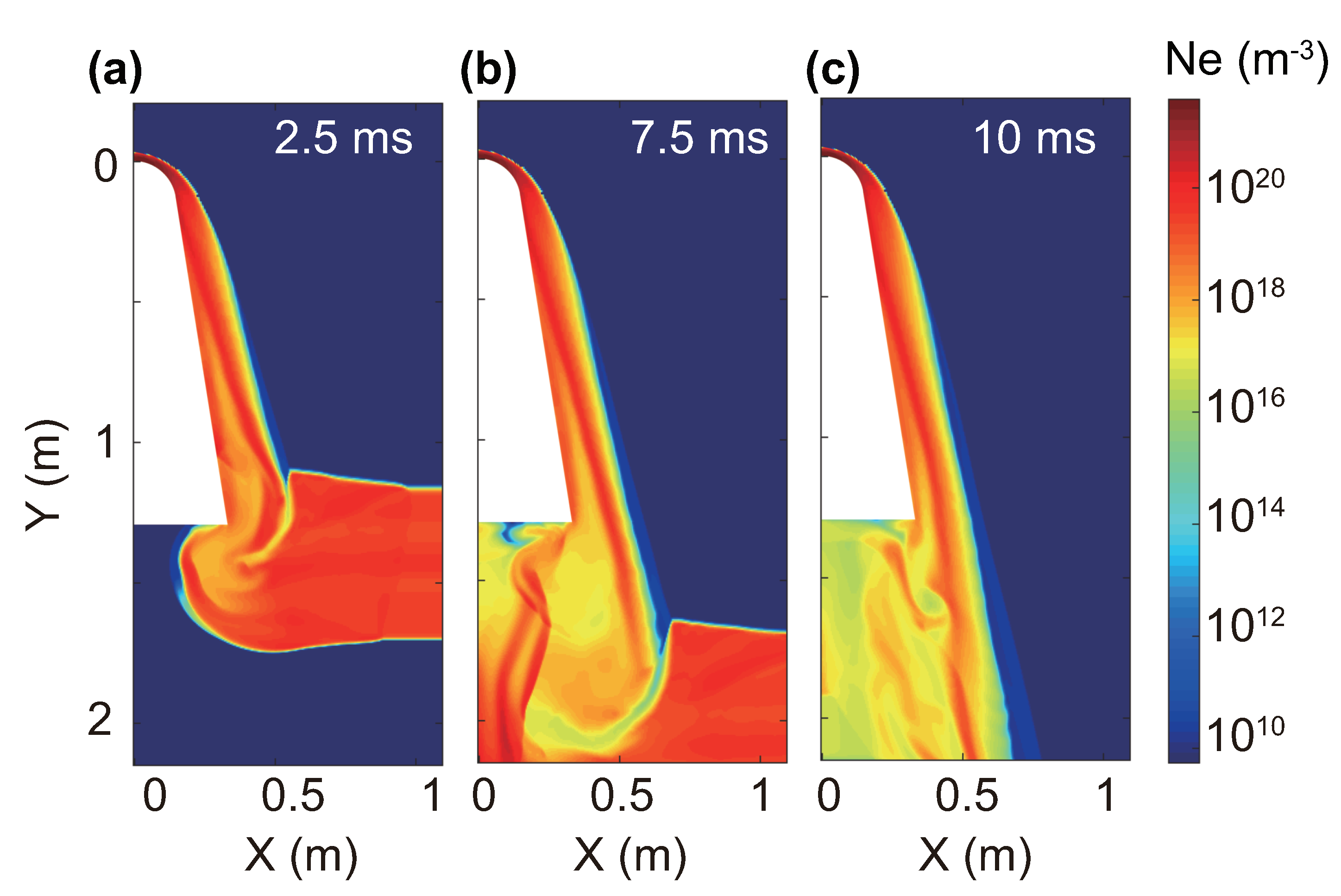
Figure 1a,b illustrates the simulation result of the plasma sheaths corresponding to the two vehicle shapes at the speed of 6550 m/s.
Figure 1a,b are the electron density distributions of the blunt-coned vehicle and sharp-coned vehicle, respectively.
Figure 1a is flipped along Y-axis to be compared with
Figure 1b. As seen in the figure, the plasma sheath distributions are quite heterogenous. The vehicle shape has an enormous influence on the plasma sheath distribution. Compared with the blunt-coned vehicle, the electron density (
) is higher near the vehicle wall of the sharp-coned vehicle. Meanwhile, the thickness of the sharp-coned vehicle’s plasma sheath is obviously smaller than that of the blunt-coned vehicle. According to
Figure 1a, the electron density near the blunt-coned vehicle nose is the highest and the electron density near the vehicle wall becomes much lower due to the evolvement of plasma. However, the situation is different in the sharp-coned vehicle plasma sheath. In
Figure 1b, the electron density is almost the same from the vehicle nose to the tail. In addition, the plasma layers of the same color are not perpendicular to the antenna radiation path according to the left zoom area of
Figure 1a. In the right zoom area of
Figure 1b, the antenna radiation path is perpendicular to the plasma layers. The difference may result in different radiation directions of the antennae mounted on the two vehicle shapes, since plasma is dispersive.
Additionally, regardless of the vehicle shape, the plasma distribution in the wake region is much more complex than the plasma distribution near the wall. The complex and unstable area is not suitable for electromagnetic wave propagation. In such cases, the vehicle sidewall would be a better choice for mounting the communication antenna. In this study, the antenna is mounted at a position nearly 0.5 m away from the vehicle nose (see the red line in
Figure 1a,c).
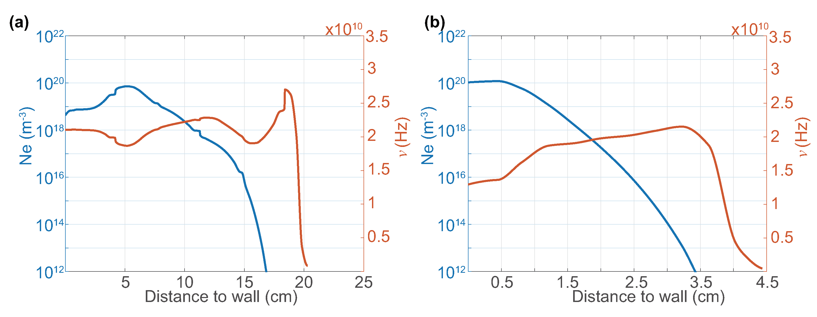
In order to investigate the impacts of the plasma sheath on antenna radiation, the electron densities and electron collision frequencies along the antenna transmission path (see gray arrows in
Figure 1a–c) are illustrated in
Figure 2a,b, respectively. The plasma sheath structures enveloping the blunt-coned vehicle and sharp-coned vehicle are clearly presented by the figure. It can be seen that the peak electron density position is 5 cm away from the blunt-coned vehicle wall. The peak electron density for the sharp-coned vehicle is at about 0.5 cm. In addition, the thicknesses of the plasma sheaths are about 20 cm and 4.5 cm. The average electron density for the sharp-coned vehicle is much higher than that for the blunt-coned vehicle. Meanwhile, the order of electron collision frequency magnitude of the plasma sheaths is almost the same, despite there being three peaks in
Figure 2a and only one peak in
Figure 2b.
The impact of plasma sheaths on antennae can be reflected by the permittivity of plasma, which affects electromagnetic wave propagation. According to the Appleton–Hartree formula [
18], the relative permittivity of plasma can be obtained with the following equation.
where
is the relative permittivity,
and
is the angular frequency of radiation.
is the angular frequency of plasma, which can be obtained with
where
is the electron number density,
is the mass of electrons, and
is the permittivity of vacuum. The antenna can only work when the operation frequency is higher than plasma cut-off frequency, which is obtained by:
Thus, the antenna must operate at higher than 75 GHz for the blunt coned vehicle since the peak electron density is
m
, according to
Figure 2. As for the sharp coned vehicle, the antenna operating frequency should be higher than 98 GHz since the peak electron density is
m
.
2.2. The 0.14 THz Array Antenna
The blackout zone is located at an altitude of 20–80 km. In this area, the water vapor attenuation of neutral atmospheric attenuation must be considered since the signal transmission path in the atmosphere could be up to several hundreds of kilometers. According to previous studies, the attenuation of THz bands at 1–10 THz is obviously much higher than that of 0.14 THz [
19]. Moreover, there are some ‘atmosphere window’ frequencies that have low attenuation levels including 35 GHz, 94 GHz, 140 GHz, and 220 GHz [
20,
21]. In such a case, it makes sense to operate the communication system at a certain atmospheric window frequency. On the other hand, the lower atmosphere window frequencies have higher signal attenuation in plasma sheaths [
8].
Additionally,
Section 2.1 proves that the antenna can only work when the operation frequency is higher than the plasma cut-off frequency. Therefore, according to Equation (
3), the antenna must operate at a frequency higher than 75 GHz for the blunt coned vehicle, since the peak electron density is
m
according to
Figure 2. As for the sharp coned vehicle, the antenna operating frequency should be higher than 98 GHz, since the peak electron density is
m
.
Therefore, in summary, to balance the signal attenuation by both the atmosphere and the plasma sheath, 0.14 THz was selected as the antenna operating frequency. The sub-THz antenna not only has low attenuation, but also high penetrability. Moreover, taking advantage of the antenna array, the antenna also has high directivity.
The structure of the 0.14 THz patched array antenna is showed in
Figure 1c. Since the plasma sheath distribution is two-dimensional, the antenna is designed to be 1 × 10 units. As seen in the figure, the antenna length is less than 1.7 cm. The antenna can be designed to have more units and can achieve extremely high directivity with acceptable antenna size. In this study, the antenna only has 10 units to reduce calculation.
2.3. Antenna Position and Suitability of 0.14 THz
Figure 3 shows the structure of the plasma sheath at three moments during its evolution. In other words,
Figure 3 shows the temporal evolution of the plasma sheath.
According to
Figure 3, the plasma distribution is very complicated at the wake. The signal SNR (signal–noise ratio) can be seriously reduced once the signals penetrate the plasma sheath via the wake region. Furthermore, there is an ‘electron wall’ near the boundary of the wake region. The signal attenuation in that region is severe. In addition, in order to penetrate the plasma sheath via the wake region, the signal propagation path in the plasma sheath is much longer than that in the region near the wall of the vehicle (aft region). The longer propagation path yields more severe total signal attenuation. In such a case, it is not appropriate to mount the communication antenna on the back of the vehicle.
In addition, in the case of carrier frequencies of 140 GHz and 225 GHz, the order of magnitude of communication system bit error rates is identical. Meanwhile, the plasma sheath has the characteristic of natural evolution (see
Figure 3 above). In the time-varying plasma sheath, the bit error rate of the 140 GHz carrier is more stable and the fluctuation of the bit error rate of 225 GHz is more frequent. Thus, we chose 0.14 THz for the communication frequency.
In summary, when the signal is radiated from the vehicle tail, the total attenuation rate of the signal is similar to that of the sidewall radiation. The main reason is that the signal needs to travel further in the wake area with relatively low electron density and then it needs to pass through the boundary layer with high electron density. In addition, the channel condition near the sidewall is more stable than that in the wake area, so the antenna is mainly considered to be arranged on the sidewall of the aircraft.
2.4. The Plasma Sheath and THz Array Antenna Coupling Models
The antenna performance can be obtained by solving the plasma antenna coupling model. The electromagnetic field
of the active antenna can be solved with the inhomogeneous Helmholtz wave equation for plane waves:
where
is the angular frequency,
is the vacuum permittivity,
is the vacuum permeability,
is the relative permittivity of plasma, and
J is the exciting current. When the equation is compared with the wave equation for propagation in vacuum, it is notable that all of the plasma-physical response is bound up in
[
22]. With the above-written equation, the near field is solved with the finite element method (FEM) [
23].
However, the FEM is not suitable for the far field calculation since the thickness of the plasma sheath in
Figure 1 is several times larger than the wavelength of 0.14 THz signals. To reduce the computation, the far field can be solved from the near field
with the integration method. The Stratton–Chu formula [
24] is used:
where
is the calculated far field in the direction from the origin towards point
p.
is the unit vector pointing from the origin to the field point
p.
is the radius vector of the surface
S.
n is the unit normal to the surface
S.
3. Antenna Radiation Performances in Different Situations
Since the antenna mounted on vehicles with different shapes is working in various plasma distribution, radiation performance can be different. In order to explore the impacts of plasma on the antenna, the antenna performance in vacuum is also simulated to be compared with antenna performance in plasma.
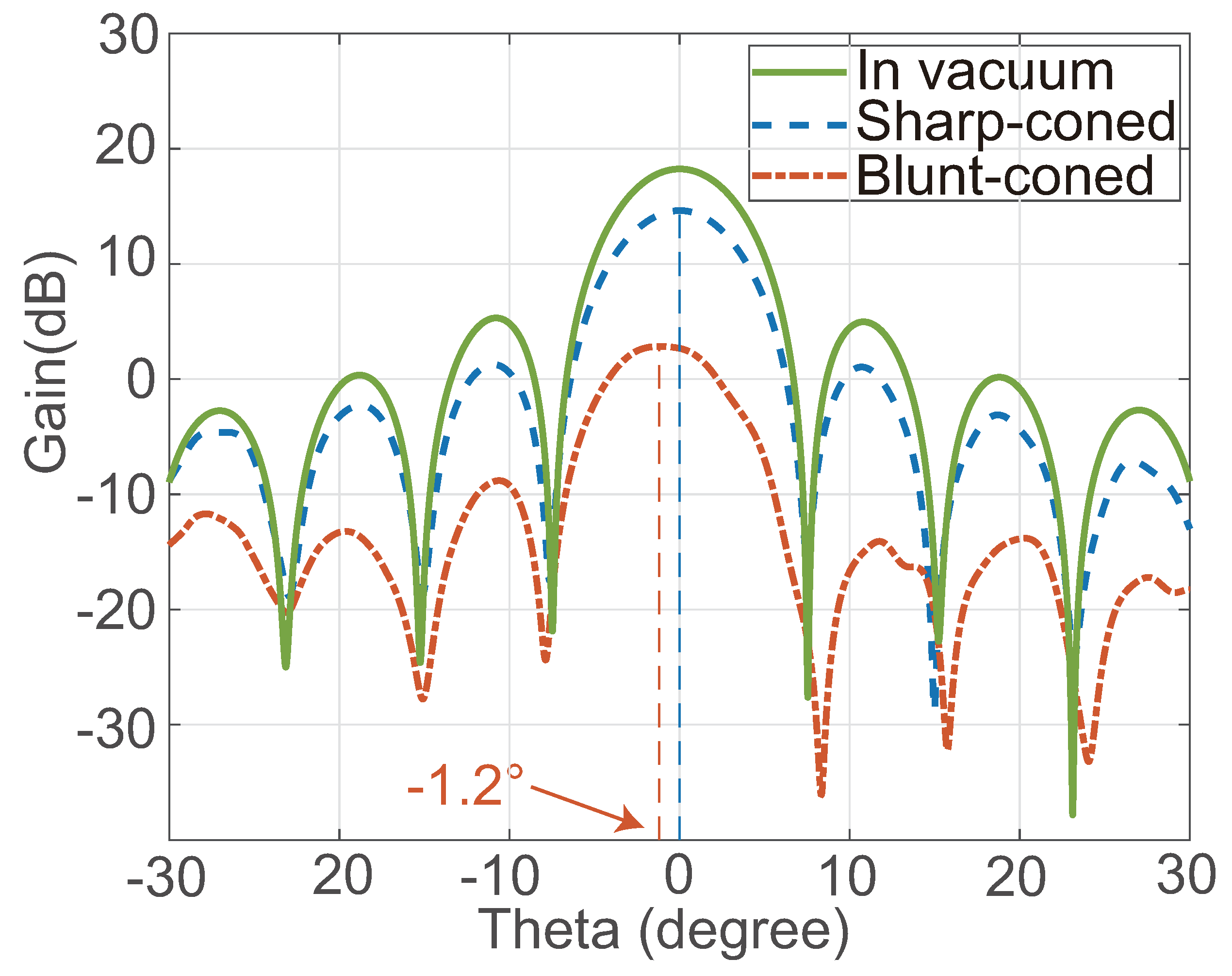
The radiation performance of the antenna in different situations is shown in
Figure 4. The green line, the red line, and the blue line represent the antenna performance in vacuum, in the blunt-coned vehicle plasma sheath, and in the sharp-coned vehicle plasma sheath, respectively. It can be seen from
Figure 4 that the three antenna mainlobes are obviously different. The detailed performance parameters are listed in
Table 1.
The antenna had highest mainlobe gain in vacuum. When the antenna is working in the plasma sheath of the sharp-coned vehicle, the result shows that the antenna gain decreased by about 2.4 dB compared with gain in vacuum. In this situation, the gain decrease is acceptable for the array antenna, since it still achieved about 14 dB gain after coupling with plasma sheath. Nevertheless, the mainlobe gain decreases to about 2.7 dB when it is operating in the plasma sheath of the blunt-coned vehicle. This indicates that the antenna radiation performance in the plasma sheath of the blunt-coned vehicle is seriously affected.
The result shows that the plasma sheath can also have impact on the antenna radiation direction. The mainlobe in the plasma sheath of the blunt-coned vehicle is pointing at , while in vacuum and the sharp-coned vehicle plasma sheath, the mainlobes are pointing at . This phenomenon illustrates that the mainlobe is refracted by the blunt-coned vehicle plasma sheath. In this situation, the gain in the target direction is further decreased, which leads to even worse communication quality.
The mainlobe width (−3 dB) is another important antenna performance parameter that is related to antenna directivity. As is shown in
Figure 4 and
Table 1, the plasma sheaths affect mainlobe width. The mainlobe width in vacuum is the smallest, which is
. When the antenna is working in plasma, the mainlobe increased to
and
. For an antenna with certain working condition, the increase of mainlobe width leads to a decrease of antenna directivity, which means the antenna performance is weakened.
4. The Model of THz Signal Attenuation in Plasma
To explain the different antenna radiation performances, a simple model was established. Since plasma parameters along the wave transmission path are strongly inhomogeneous, the propagation constant for the concerned signals in the plasma sheath is expressed as [
2]:
The transmitted signal is obtained by:
where
L is the total length of the transmission path,
is the electric field for the transmitted wave, and
is the electric field for the incident wave. With Equations (6) and (7), the transmitted signal intensity in different plasma sheaths can be obtained with the scattering matrix method (SMM).
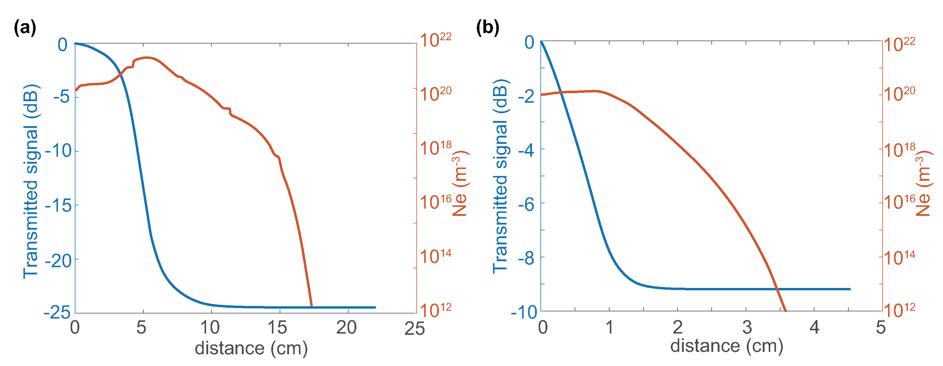
Figure 5 shows the signal attenuation in plasma sheaths. The phenomenon is known as the ‘skin depth’. The signal attenuation relates to electron density and electron collision frequency according to the above equations. However, the order of magnitude of maximum electron density and maximum electron collision frequency of the two plasma sheaths are almost the same. In such cases, the plasma thickness becomes the determinant of signal attenuation. The thickness of the sharp-coned vehicle plasma sheath is smaller. Therefore, the performance of the sharp coned vehicle antenna is better. It should be noticed that the model is two-dimensional. Therefore, the signal attenuation is not the same as the result in
Figure 4.
5. Analysis and Discussion
Previous research has revealed that the plasma sheath can impact the electromagnetic wave propagation, which can result in antenna performance changes. In this study, the coupling of the antenna and plasma shows that radiation performance is worsened compared with performance in vacuum. However, the study focuses on the radiation performance in plasma sheaths of two different vehicle shapes: the blunt-coned shape and the sharp-coned shape. Different vehicle shapes lead to different plasma sheath distributions. The antenna mounted on the sharp-coned vehicle has better radiation performance than the same antenna mounted on the blunt-coned vehicle. According to the results in
Figure 1 and
Figure 2, the main differences between the two plasma sheaths are plasma thickness, electron distribution, and electron collision frequency distribution. The three parameters reflect different relative permittivity distributions.
It can be seen from Equation (
1) that plasma relative permittivity consists of the real part and the imaginary part. The real part of relative permittivity is related to refraction and reflection. The ratio of the real part to the imaginary part is related to plasma dielectric loss. In this study, according to Equation (
1), the imaginary part of relative permittivity is small. Compared with the influence of refraction and reflection, dielectric loss in plasma can be ignored. According to
Figure 2, in the two plasma sheath distributions, the real part of the relative permittivity along the transmission path decreases from an initial value to a minimum, and then increases to 1 (the relative permittivity of neutral air). The minimum value difference of relative permittivity in the two situations, which is mainly decided by peak electron density, is small. Therefore, the main character that influences the antenna gain should be plasma thickness, and larger plasma thickness leads to lower antenna performance. This can explain the phenomenon that antenna mainlobe gain in the blunt-coned vehicle plasma is much lower than in the sharp-coned vehicle plasma.
In addition, it should be noticed that the plasma layers corresponding to different orders of magnitude of electron density are not parallel to the vehicle wall in
Figure 1a. Since plasma is a dispersive medium, the plasma distribution can form a lens-like structure and refract the antenna radiation lobe. However, the layers for the sharp-coned vehicle are parallel to the wall. In such a case, the radiation direction shift in the blunt-coned vehicle plasma can be explained.
The results reveal that the sharper vehicle can lead to a smaller plasma sheath thickness and less impact on antenna performance. However, the sharper nose result in higher plasma electron density, which leads to a higher plasma cut-off frequency. The antenna can only perform well when the operating frequency is higher than the plasma sheath cut-off frequency. In such cases, the antenna should be designed to operate at a higher frequency. Nevertheless, for a specific communication system, the maximum operation frequency is fixed. Overall, the shape of the vehicle should be designed based on the actual demand. The shape of the vehicle should be as sharp as possible with the condition that the onboard antenna operation frequency is higher than the plasma sheath cut-off frequency.
6. Conclusions
In the present study, the impacts of vehicle shape on the hypersonic plasma sheath were investigated numerically. Based on the 0.14 THz array antenna and plasma sheath coupling model, the influence of vehicle shape on antenna radiation performance was explored. The result shows that different vehicle shapes will lead to different plasma sheath distributions and result in quite different antenna performances. The following conclusions are drawn:
1. The plasma sheath distribution of different vehicle shapes is quite different and radiation performance is seriously affected by the plasma sheath;
2. For a coned vehicle, as the vehicle nose becomes sharper, the plasma sheath thickness becomes smaller, while the peak electron density becomes higher. In the same working conditions, the antenna performance improves as the vehicle nose becomes sharper.
3. The blunt-coned vehicle plasma sheath will form a lens-like structure and refract the mainlobe of an antenna mounted on the vehicle sidewall. The phenomenon does not exist in the situation of the sharp-coned vehicle plasma sheath.
4. With the condition that the onboard antenna operation frequency be higher than the plasma sheath cut-off frequency, the shape of the vehicle should be designed to be as sharp as possible to guarantee antenna performance.
Author Contributions
Conceptualization, Z.Z., B.B., K.Y. and R.T.; methodology, Z.Z. and K.Y.; validation, Z.Z., J.X. and K.W.; formal analysis, Z.Z.; investigation, Z.Z.; resources, Z.Z.; data curation, Z.Z.; writing—original draft preparation, Z.Z.; writing—review and editing, K.Y. and R.T.; visualization, Z.Z.; supervision, K.Y. and R.T.; project administration, Z.Z.; funding acquisition, K.Y. All authors have read and agreed to the published version of the manuscript.
Funding
This work was supported by the National Natural Science Foundation of China (Grant No. 41727804, 41974195 and 61861031), and the Interdisciplinary Innovation Fund of Natural Science from Nanchang University under grant 9166-27060003-YB14.
Institutional Review Board Statement
Not applicable.
Informed Consent Statement
Not applicable.
Data Availability Statement
Conflicts of Interest
The authors declare no conflict of interest.
References
- Stollery, J. Hypersonic flight. Nature 1972, 240, 133–135. [Google Scholar] [CrossRef]
- Rybak, J.P.; Churchill, R. Progress in reentry communications. IEEE Trans. Aerosp. Electron. Syst. 1971, AES-7, 879–894. [Google Scholar] [CrossRef]
- Akey, N.D. Overview of RAM reentry measurements program. NASA Spec. Publ. 1971, 252, 19. [Google Scholar]
- Cross, A.; Jones, W., Jr. Electrostatic Probe Measurements of Plasma Surrounding Three 25,000 Foot per Second Reentry Flight Experiments; 1970; Available online: https://ui.adsabs.harvard.edu/abs/1971NASSP.252..109L/abstract (accessed on 3 January 2022).
- Sims, T.E.; Jones, R.F. Flight measurements of VHF-signal attenuation and antenna impedance for the RAM A-1 slender probe at velocities up to 17,800 feet per second. In NASA TM X-760; 1963; Available online: https://xueshu.baidu.com/usercenter/paper/show?paperid=150d0vr0v02p0850bq700tq0w3149555 (accessed on 3 January 2022).
- Cuddihy, W.F.; Beckwith, I.E.; Schroeder, L.C. RAM B2 Flight Test of a Method for Reducing Radio Attenuation during Hypersonic Reentry. In NASA TM X-902; 1963; Available online: https://www.researchgate.net/publication/24328978_RAM_B2_flight_test_of_a_method_for_reducing_radio_attenuation_during_hypersonic_reentry (accessed on 3 January 2022).
- Chen, J.; Yuan, K.; Shen, L.; Deng, X.; Hong, L.; Yao, M. Studies of terahertz wave propagation in realistic reentry plasma sheath. Prog. Electromagn. Res. 2016, 157, 21–29. [Google Scholar] [CrossRef] [Green Version]
- Tang, R.; Mao, M.; Yuan, K.; Wang, Y.; Deng, X. A terahertz signal propagation model in hypersonic plasma sheath with different flight speed. Phys. Plasmas 2019, 26, 043509. [Google Scholar] [CrossRef]
- Tian, Y.; Han, Y.; Ling, Y.; Ai, X. Propagation of terahertz electromagnetic wave in plasma with inhomogeneous collision frequency. Phys. Plasmas 2014, 21, 023301. [Google Scholar]
- Zheng, L.; Zhao, Q.; Liu, S.; Xing, X.; Chen, Y. Theoretical and experimental studies of terahertz wave propagation in unmagnetized plasma. J. Infrared Millim. Terahertz Waves 2014, 35, 187–197. [Google Scholar] [CrossRef]
- Bai, B.; Liu, Y.; Lin, X.; Li, X. Effects of a reentry plasma sheath on the beam pointing properties of an array antenna. AIP Adv. 2018, 8, 035023. [Google Scholar]
- Yuan, K.; Wang, Y.; Shen, L.; Yao, M.; Deng, X.; Zhou, F.; Chen, Z. Sub-THz signals’ propagation model in hypersonic plasma sheath under different atmospheric conditions. Sci. China Inf. Sci. 2017, 60, 113301. [Google Scholar] [CrossRef] [Green Version]
- Yuan, K.; Yao, M.; Shen, L.; Deng, X.; Hong, L. Studies on the effect of angle of attack on the transmission of terahertz waves in reentry plasma sheaths. Prog. Electromagn. Res. M 2017, 54, 175–182. [Google Scholar] [CrossRef] [Green Version]
- Tang, R.; Xiong, Z.; Yuan, K.; Mao, M.; Wang, Y.; Deng, X. EHF Wave Propagation in the Plasma Sheath Enveloping Sharp-Coned Hypersonic Vehicle. IEEE Antennas Wirel. Propag. Lett. 2021, 20, 978–982. [Google Scholar] [CrossRef]
- Bai, B.; Li, X.; Liu, Y.; Xu, J. Effects of reentry plasma sheath on mutual-coupling property of array antenna. Int. J. Antennas Propag. 2015, 2015, 1–9. [Google Scholar] [CrossRef]
- Yuan, K.; Chen, J.; Shen, L.; Deng, X.; Yao, M.; Hong, L. Impact of reentry speed on the transmission of obliquely incident THz waves in realistic plasma sheaths. IEEE Trans. Plasma Sci. 2018, 46, 373–378. [Google Scholar] [CrossRef]
- Jones, W.L.; Cross, A.E. Electrostatic-Probe Measurements of Plasma Parameters for Two Reentry Flight Experiments at 25,000 Feet per Second; National Aeronautics and Space Administration: Washington, DC, USA, 1972; Volume 6617.
- Davies, K. Ionospheric Radio Propagation; US Department of Commerce; National Bureau of Standards: Gaithersburg, MD, USA, 1965; Volume 80.
- Sun, J.; Hu, F.; Lucyszyn, S. Predicting atmospheric attenuation under pristine conditions between 0.1 and 100 THz. IEEE Access 2016, 4, 9377–9399. [Google Scholar] [CrossRef] [Green Version]
- Liebe, H. Atmospheric EHF window transparencies near 35, 90, 140 and 220 GHz. IEEE Trans. Antennas Propag. 1983, 31, 127–135. [Google Scholar] [CrossRef]
- Sen, A.; Karmakar, P.; Dev Gupta, A. A theoretical estimate of tropospheric water vapour attentuation at 94 GHz from radiosonde data. Int. J. Remote Sens. 2007, 9, 1259–1266. [Google Scholar] [CrossRef]
- James, H.G. A review of the major developments in our understanding of electric antennas in space plasmas. URSI Radio Sci. Bull. 2011, 2011, 75–94. [Google Scholar]
- Bathe, K.J. Finite element method. In Wiley Encyclopedia of Computer Science and Engineering; John Wiley & Sons, Inc.: New York, NY, USA, 2007; pp. 1–12. [Google Scholar]
- Stratton, J.A.; Chu, L. Diffraction theory of electromagnetic waves. Phys. Rev. 1939, 56, 99. [Google Scholar] [CrossRef]
| Publisher’s Note: MDPI stays neutral with regard to jurisdictional claims in published maps and institutional affiliations. |
© 2022 by the authors. Licensee MDPI, Basel, Switzerland. This article is an open access article distributed under the terms and conditions of the Creative Commons Attribution (CC BY) license (https://creativecommons.org/licenses/by/4.0/).


