Article

Pumped Thermal Energy Storage System for Trigeneration: The Concept of Power to XYZ

by
Evangelos Bellos
*,
Panagiotis Lykas
and
Christos Tzivanidis
Thermal Department, School of Mechanical Engineering, National Technical University of Athens, Zografou, Heroon Polytechniou 9, 15780 Athens, Greece
*
Author to whom correspondence should be addressed.
Appl. Sci. 2022, 12(3), 970; https://doi.org/10.3390/app12030970
Submission received: 30 December 2021 / Revised: 15 January 2022 / Accepted: 16 January 2022 / Published: 18 January 2022
(This article belongs to the Section Mechanical Engineering)

Abstract

:
The objective of this investigation is to present a novel concept for the optimum exploitation of volatile electricity from renewable energy sources. The idea of the Carnot battery is extended to a general concept for trigeneration which can be called “power to XYZ”. This idea is applied for the building sector where there are needs for cooling production, space-heating production/domestic hot water production and electricity. More specifically, volatile electricity feeds a multi-stage heat pump that produces cold storage at 0 °C for cooling, medium heating storage at 50 °C for space heating and high thermal storage at around 115 °C for future utilization in an organic Rankine cycle for electricity production. The storage is performed in three different temperature levels, with latent storage proposed for proper long-term and efficient storage. The use of ice is suggested especially for cold storage in order to make the design a cost-effective one. This work is a theoretical preliminary thermodynamic analysis performed with a model created in Engineering Equation Solver. The results indicate the system’s maximum exergy efficiency is found at 45.28%, while the respective energy efficiency is found at 322.16%. Moreover, this work includes parametric studies and calculations about the operating margins of the suggested system.

1. Introduction

The increasing exploitation of renewable energy sources [1] creates the need for the development of new and efficient storage systems in order to properly store volatile electricity [2]. These storage systems have to be efficient, low-cost and reliable in order to lead to suitable energy storage [3]. A lot of relevant research has been performed in recent years and different ideas have been investigated theoretically and experimentally.
One of the more pioneering ideas is the use of the “Carnot battery” [4]. According to this concept, volatile electricity from the grid feeds a heat pump and high temperature (>100 °C) is stored in a proper storage device. When there is electricity demand, this stored heat is used as the heat source of a thermodynamic cycle in order to again produce electricity [5]. The most common thermodynamic cycles are the organic Rankine cycle (ORC) [6] and the Joule–Brayton cycle [7]. Various ideas have been examined about storage systems in the literature, including sensible storage [8], latent storage [8], thermochemical storage [9] and the packed bed storage system [10]. Moreover, there are ideas about using solar energy [11], waste heat recovery [12], or geothermal energy [13] as heat inputs in the heat pump for enhancing the round-trip efficiency of these systems (ratio of the output electricity to the charging electricity).
There are numerous published investigations in the literature for the Carnot battery system with various alternative designs. Characteristic is the theoretical study of Eppinger et al. [8] that compared a heat pump–ORC system (HP–ORC) with sensible and latent storage systems, as well as for different heat input temperature levels on the heat pump’s evaporator. They concluded that the use of a latent storage system is a more efficient choice than the use of sensible storage. In addition, they concluded that the working fluid R1233zd(E) is the best choice for the sensible storage case, while cyclopentane is the optimal choice for latent storage systems. In another study, Bellos et al. [11] suggested the use of flat plate solar technologies for feeding the heat pump; they found that this technique increases the round-trip efficiency to 68.5% compared to 32.1% for the ambient source heat pump. They also calculated the payback period of the solar field investment at about 7.5 years. In the same direction, Schimpf and Span [14] suggested a solar and geothermal-driven heat pump with a reversible ORC. This design was proved to be a cost-effective choice with important advantages. Moreover, the idea of the reversible HP–ORC with waste heat recovery has been examined by Mateu-Royo et al. [15]. They found that the most appropriate fluids are the R-1224yd(Z) and R-1233zd(E). The system operates with a coefficient of performance at 2.44 and electrical efficiency of 8.75%. Furthermore, there are interesting studies in the literature that incorporate nuclear energy in thermal-pumped systems [16], as well as geothermal energy [17]. Especially in the case of geothermal energy exploitation, geothermal heat pumps are efficient choices that are promising for future highly efficient systems [18].
The previous literature summary highlights that there is great interest in the domain of Carnot batteries and the respective storage systems. Virtually all the literature studies are focused on systems that exploit grid electricity to an intermediate product “X”, which is usually high thermal stored energy, and after a period this quantity “X” is reconverted to electricity. However, there is a lack of research about trying to convert grid electricity into more intermediate products. In this direction, the present work suggests for the first time a new concept that combines the Carnot battery idea and trigeneration. Specifically, volatile electricity from the grid feeds a multi-stage heat pump that produces cooling, space heating and high thermal stored energy. So, the concept of “Power to XYZ” is born with the present work in a trial for the optimal utilization of the electricity grid which is stored in various forms of energy. At this point, it is important to state that the trigeneration systems, especially when they are driven by renewables, are viable choices for future sustainable development [19]. So, the new concept of “Power to XYZ” is a critical one because it aims to combine two “hot topics”: “Power to X” and “trigeneration”.
Thus, this work examines a multi-stage heat pump as the core device of the pumped thermal energy storage unit for trigeneration which is coupled with three latent storage tanks. The low-temperature tank stores cold energy in ice at 0 °C and the medium-temperature tank stores heat in the phase change material (PCM) at 50 °C, while the third storage is performed on the high-temperature latent system around 115 °C. Low-temperature storage is suitable for cooling, medium for space heating/domestic hot water and high-temperature storage will feed an ORC for electricity recovery. This is the trigeneration format of the system, while it can also be a cogeneration unit in winter by stopping the operation of the lower stage. Different parameters of this system are investigated and their performance is evaluated in each case. Moreover, the operating margins of the system are determined. The analysis is performed by developing a model using the software Engineering Equation Solver (EES) [20].

2. Material and Methods

This section presents the proposed system and the respective mathematical component for its proper simulation. In addition, the simulation details of this work are included.

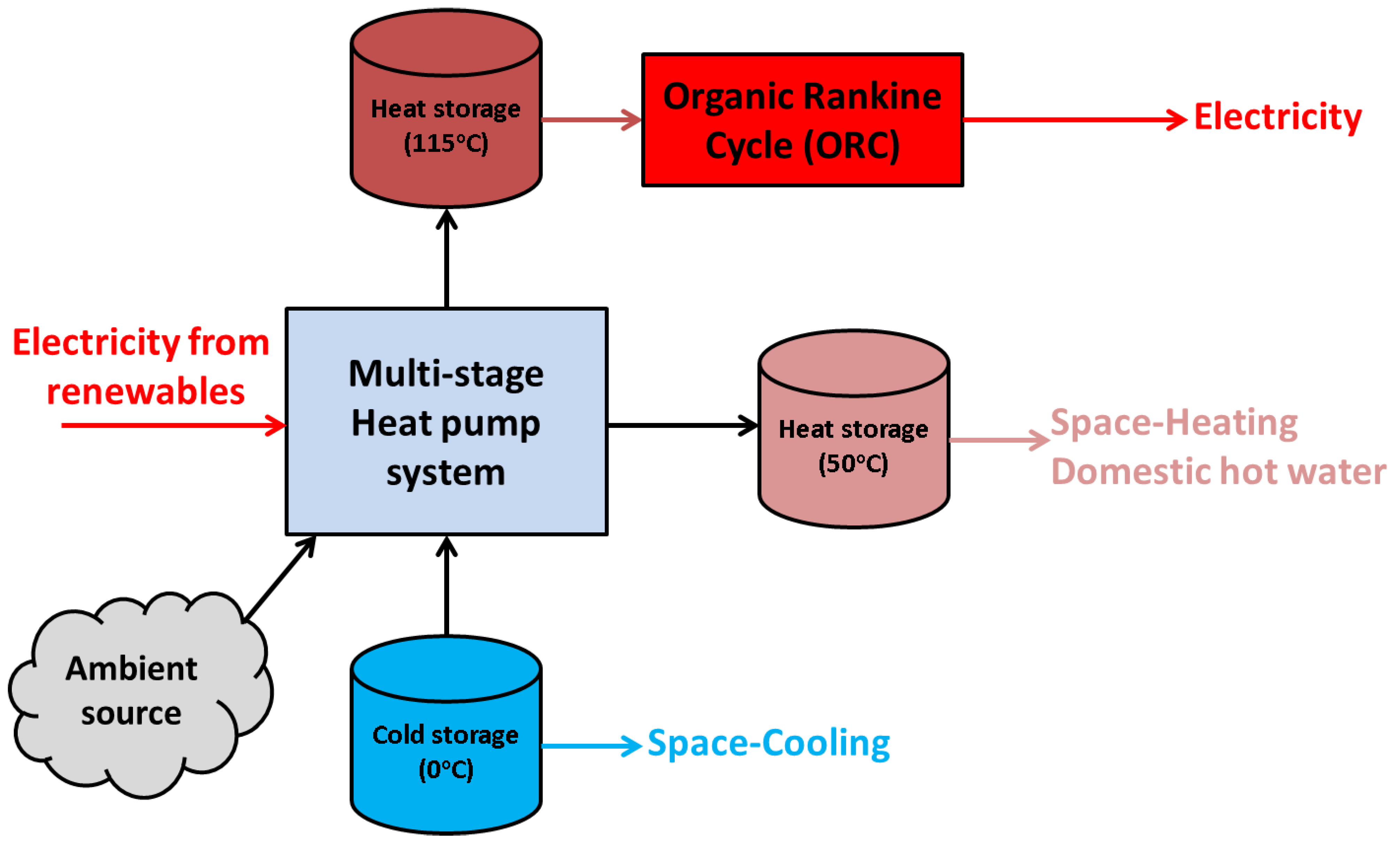
2.1. The Concept of the Pumped Thermal Energy Storage Unit for Trigeneration

The present work outlines the idea of exploiting volatile electricity from renewables in order to convert it into three useful products that can be properly stored. Figure 1 demonstrates this idea with a simplistic depiction. The core of the system is a multi-stage heat pump that is fed by the ambient source and from cold input which is responsible for the cooling loads. The heat pump rejects heat to the medium temperature level, around 50 °C, in a heat storage system for space-heating purposes and/or domestic hot production. Furthermore, the heat pump is able to produce high heating temperatures, e.g., around 115 °C, for high-temperature storage. This high quantity can be used in an ORC for electricity recovery when there is a need. At this point, high-temperature thermal storage can also be used in alternative applications such as industrial processes (e.g., drying), but it is not in the scope of the present work which focuses on building applications.
The storage of thermal/cold energy is a critical issue because it has to be both efficient and kept for significant time periods. Thus, this work suggests the use of latent storage systems. Evidence suggests that the use of ice storage is a cost-effective solution for cold storage at 0 °C. The other storage systems, medium and high-temperature levels, have to use phase change material (PCM) with melting temperature at 50 °C and at 115 °C, respectively. At this point, it is useful to highlight that the cold-storage temperature (0 °C) and the medium-storage temperature (50 °C) are fixed in this study, while the high-temperature level of the storage is variable. It is important to note that for the high temperature, the value of 115 °C is a typical choice in order to have high performance and not to face difficulties with the turbomachinery and other devices.
The suggested unit is ideal for buildings and can be applied from low scale up to high scale. There is the scope to adjust the system capacity according to the building needs, plus this system with latent storage can be a compact design with the possibility of long-term storage for several weeks.
The next step in this study is the description of the multi-stage heat pump, as well as the total configuration in detail. Figure 2 shows the total configuration, while Figure 3 describes the regenerative ORC. According to Figure 2, the suggested heat pump has three compressors and operates at four temperature levels: the low temperature (Tlow), which is 5 K lower than cold storage; the (Tin-am), which is 5 K greater than the ambient temperature; the (Theat,m), which is 5 K greater than the medium storage temperature; and the (Theat,h), which is 5 K greater than the high thermal storage temperature. These temperature differences of 5 K are selected as typical values for efficient and proper heat transfer.
The ambient source is used in order to counterbalance the system loads. Moreover, during the winter period there are no cooling needs, so the system can operate without the lower-stage compressor. In this scenario, the system operates as a cogeneration unit. Thus, at this point, it is important to separate the following operating scenarios:
(A) Trigeneration operation: All the compressors are open and all the devices are used.
(B) Cogeneration operation: The compressor (a) of the lowest stage is closed and there is no cold storage.
In relation to the system description, it is worth noting that the working fluid is cyclopentane in both the heat pump and the ORC. This is a proper selection according to previous studies [8,11]. Interestingly, in Figure 2, after the compressor (b), there is heat extraction up to the saturated point (6) and after the flow is separated. This strategy makes possible the minimization of the power consumption in the compressor (c). The device (Heat HEX) performs an intermediate cooling of the fluid and the heat that is rejected from the system is utilized in the medium storage tank; thus, there is optimal heat management. Another issue is the use of an internal heat exchanger (HEX) in the upper stage in order to increase the performance and to compress without inserting to the two-phase conditions.
Figure 3 shows the ORC, which is a regenerative system for achieving high thermodynamic efficiency. Cyclopentane is considered to be an efficient choice as the working medium in the ORC [8,11]. The ORC rejects heat to the ambient as it is performed in usual designs. This technique is followed in the current work but the present system gives an extra opportunity to cool the ORC with cold storage when there are no cooling loads. However, this is a very specific scenario and outside the scope of this study; thus, this work uses the ambient as the rejection heat sink of the ORC. The ORC is selected to operate with superheating of 5 K in the turbine inlet, while its condenser temperature is 5 K above the ambient temperature level.

2.2. Mathematical Formulation Part

This section presents the basic modeling of the studied configuration. The given formulas relate to the energy balance in the examined devices and related correlations.

2.2.1. Heat Pump Modeling

The cooling production (Qcool) can be written as:
Q c o o l = m a h 1 h 15
The heat input from the ambient (Qin) can be written as:
Q i n = m d h 3 h 14
The medium-temperature heat production (Qheat,m) can be written as:
Q h e a t , m = m b h 5 h 6 + m e h 6 h 12
The high-temperature heat product (Qheat,h) can be expressed as:
Q h e a t , h = m c h 8 h 9
The electricity consumption of the compressor (a) can be written as:
P e l , a = m a h 2 h 1 η m
The isentropic efficiency of the compressor (a) can be written as:
η i s , a = h 2 , i s h 1 h 2 h 1
The electricity consumption of the compressor (b) can be written as:
P e l , b = m b h 5 h 4 η m
The isentropic efficiency of the compressor (b) can be written as:
η i s , b = h 5 , i s h 4 h 5 h 4
The electricity consumption of the compressor (c) can be written as:
P e l , c = m c h 8 h 7 η m
The isentropic efficiency of the compressor (c) can be written as:
η i s , c = h 8 , i s h 7 h 8 h 7
The total electricity input (Pel,in) in the trigeneration scenario is:
P e l , i n = P e l , a + P e l , b + P e l , c
For the cogeneration scenario, the term (Pel,a) is set to zero.
The mixing at the state-point (4) can be modeled with the mass flow rate balance plus the respective energy rate balance as:
m a + m d = m b
m a h 2 + m d h 3 = m b h 4
The energy balance in the internal heat exchanger can be written as:
h 7 h 6 = h 9 h 10
The heat transfer in the internal heat exchanger is modeled with the minimum approach temperature difference:
T 7 = T 9 Δ Τ H E X
The mixing at the state-point (13) can be modeled with the mass flow rate balance and the respective energy balance as:
m c + m e = m f
m c h 11 + m e h 12 = m f h 13
Additionally, the mass flow rate balance in the state-point (14), in combination with the mass flow rate balance in the state-point (4), can express the (mf) as:
m f = m b
The throttling valves in the system reduce the pressure to the proper levels without thermal losses to the ambient. Thus, the inlet enthalpy is the same as the outlet enthalpy. Therefore, it can be written for the respective processes:
h 11 = h 10
h 14 = h 13
h 15 = h 14
Lastly, the state points (1), (3) and (6) are saturated vapor, while the state points (9) and (12) are saturated liquid.

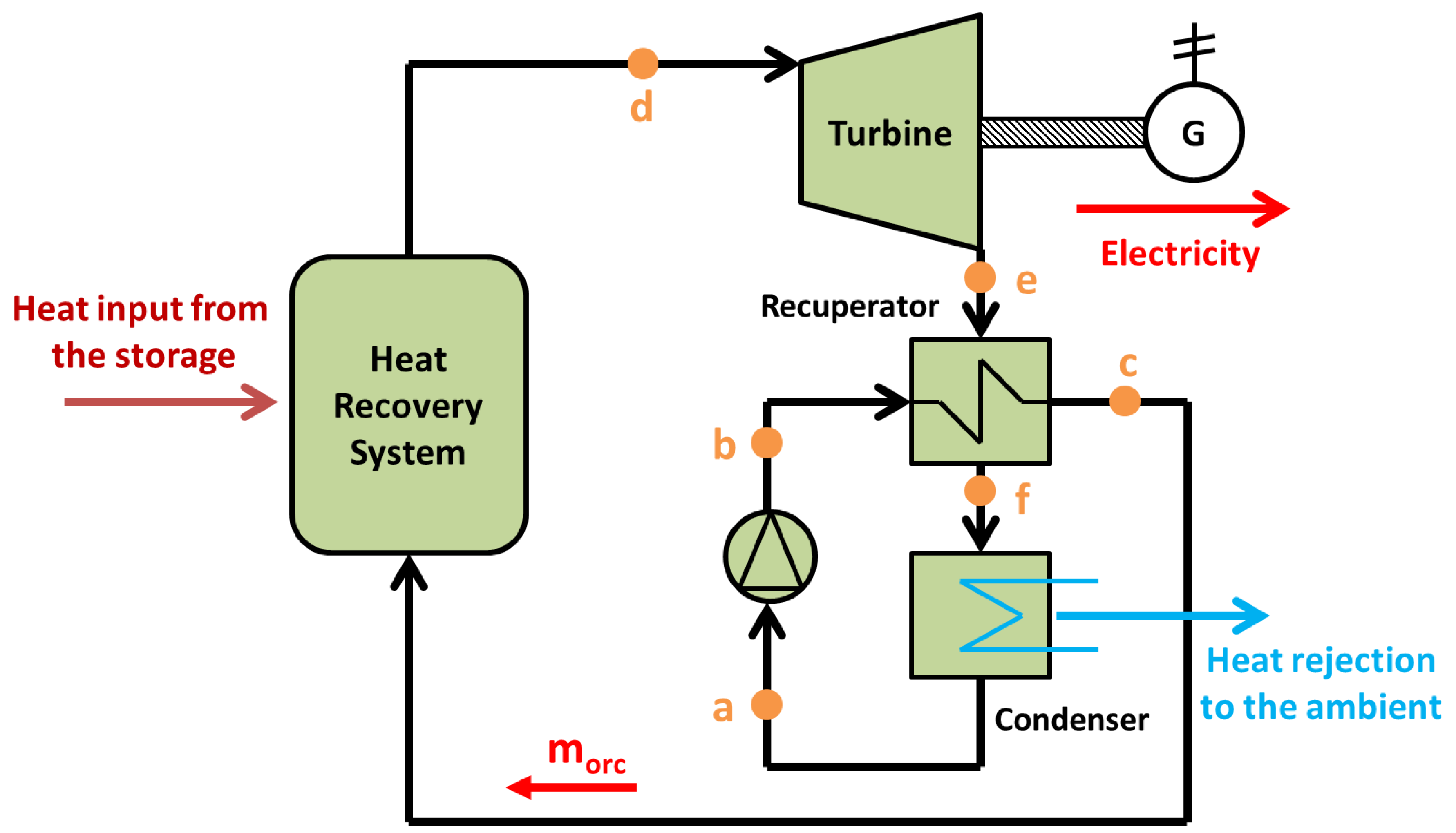
2.2.2. Organic Rankine Cycle Modeling

The ORC is modeled by using the following set of equations. These equations are typical formulas about the energy balances in the various devices and respective efficiency definitions.
The heat exchange in the heat recovery system (HRS) can be written as:
Q H R S = m o r c h d h c
The electricity output from the ORC (Pel,out) is calculated by using the produced electricity from the generator minus the electricity consumption from the organic fluid pump and can be written as:
P e l , o u t = η m g m o r c h d h e m o r c h b h a η m o t o r
The isentropic efficiency for the organic fluid pump (ηis,pump) can be written as:
η i s , p u m p = h b , i s h a h b h a
The isentropic efficiency for the organic fluid turbine (ηis,tur) can be written as:
η i s , t u r = h d h e h d h e , i s
The heat rate balance of the recuperator can be written as:
h c h b = h e h f
The heat transfer modeling in the recuperator is conducted by using the minimum temperature difference concept and can be written as:
T f = T b + Δ Τ r e c
The heat output of the ORC to the ambient heat sink (Qout) can be written as:
Q o u t = m o r c h f h a
It is worth mentioning that the minimum temperature difference on the HRS (pinch point) is set at 5 K. Furthermore, it is significant that the outlet of the heat rejection device (state point a) is selected to be a saturated liquid.
Lastly, the thermodynamic efficiency of the organic Rankine cycle (ηorc) is given as:
η o r c = P e l , o u t   Q H R S

2.2.3. Evaluation Indexes

The system is investigated thermodynamically in the present work, making reasonable assumptions about its real operation. The energy and the exergy efficiencies are the main evaluation criteria used.
The system energy efficiency (ηen,sys) is defined as:
η e n , s y s = Q c o o l + Q h e a t , m + P e l , o u t P e l , i n
The system exergy efficiency (ηex,sys) is defined as:
η e x , s y s = Q c o o l 273.15 + T a m 273.15 + T c o o l 1 + Q h e a t , m 1 273.15 + T a m 273.15 + T h e a t , m + P e l , o u t P e l , i n
At this point, it is important to note that the system energy efficiency, generally, takes values above 100%, while the system exergy efficiency is always lower than 100%. The high values of the energy efficiency are justified and reasonable because the present system acts as a heat pump. However, it is unable to use the term “Coefficient of Performance” because this system also has electricity as a useful output. Thus, the present system is not a “heat pump” but it behaves similar to one and therefore its energy efficiency can exceed 100%. Moreover, it is important to note that the system exploits the cooling input and the ambient source inputs in order to produce heating of medium and high-temperature levels. Therefore, the way that the system finds its energy inputs are reasonable and it does not violate any thermodynamic rule. This is also obvious based on the values of exergy efficiency which are usually in the range of 40–45%.

2.3. Simulation Methodology

The present investigation is a thermodynamic study performed in steady-state conditions. A thermodynamic model based on the equations of Section 2.2 has been written in a program in the Engineering Equation Solver (EES) [20]. The steady-state analysis enables the investigation of the system to be conducted without studying the long-term storage of the unit, while the thermal losses of the system are neglected. This aspect will be examined in future work about this system. Table 1 shows the two main scenarios of the system operation that are examined, namely the trigeneration in summer and the cogeneration in winter.
The simulation details, including all the simulation data, are presented in Table 2. Specifically, the selected efficiency values, the selected temperature levels and a range of other simulation parameters are included in this table. During simulations, different parameters are investigated in order to present the unit’s performance for various operating cases. In particular, the system is examined for different values of the high-temperature level (Theat,h) which is a crucial design parameter, as well as for different ambient temperatures. It is worth noting that for ambient temperature levels lower than 20 °C, it is assumed to have a cogeneration system, while for temperature levels above 20 °C the trigeneration operation is selected. This is a simple and practical technique in order to separate the two examined scenarios. Moreover, different values of the loads (Qcool, Qheat,m and Qheat,h) are examined. In the last step of this investigation, the operating margins of the unit are defined in order to map the possible operating conditions. Practically, the ambient heat input is a critical parameter that can be used to counterbalance and cover the needed loads.

3. Results

This section presents the simulation results of the investigated model. These results consider parametric studies of the investigated configuration in order to present its performance in different conditions and in different operating scenarios.

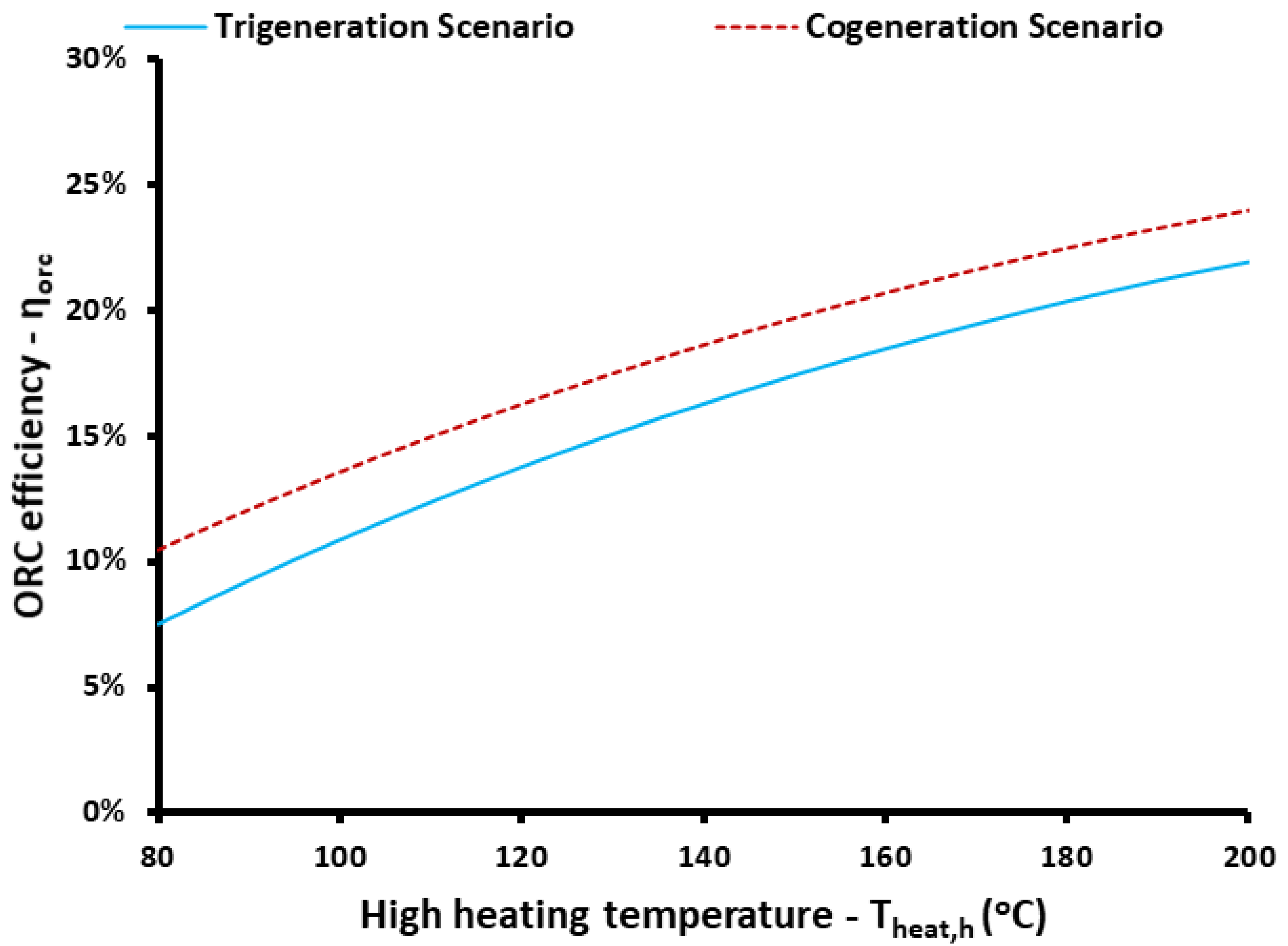
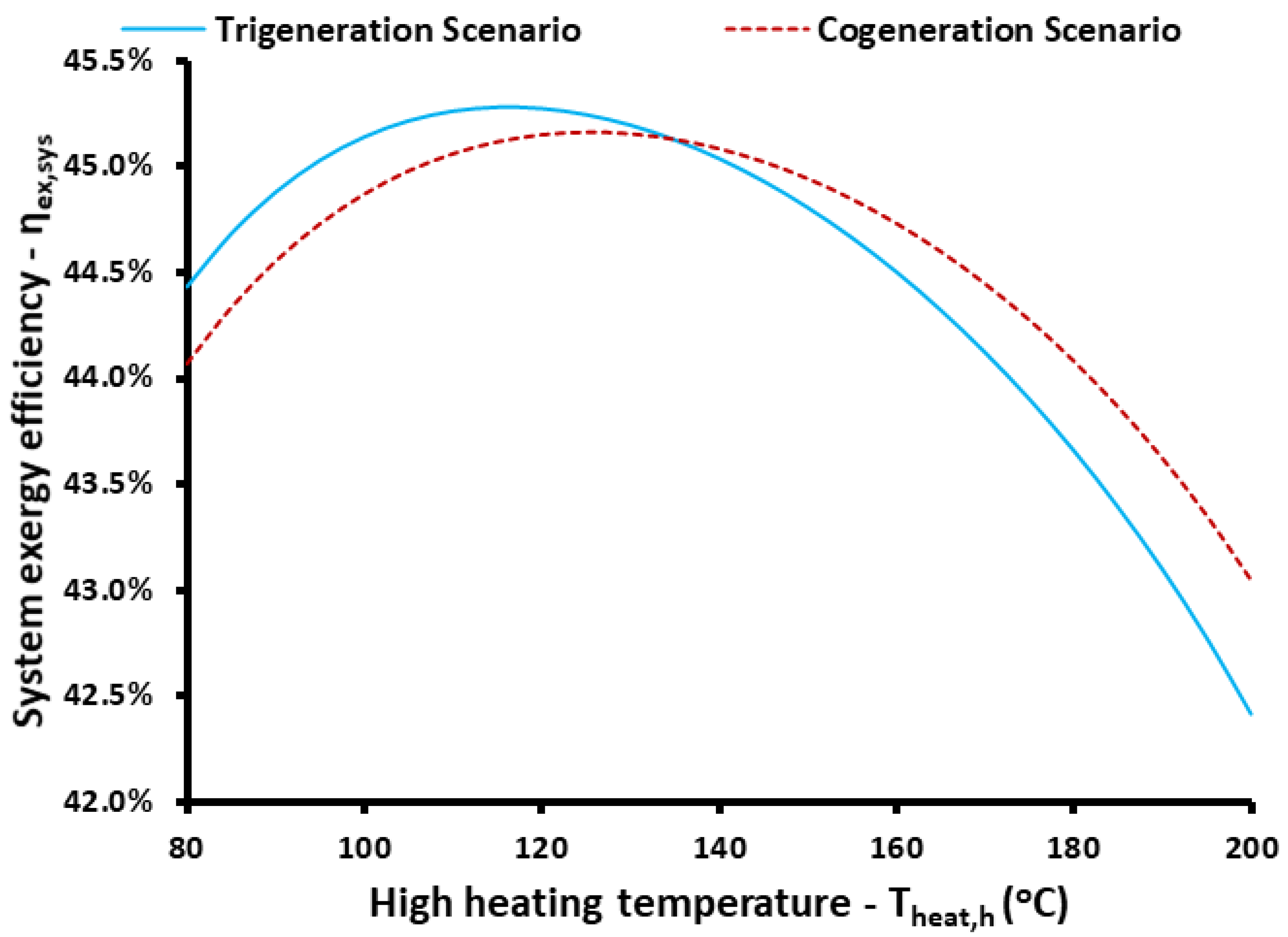
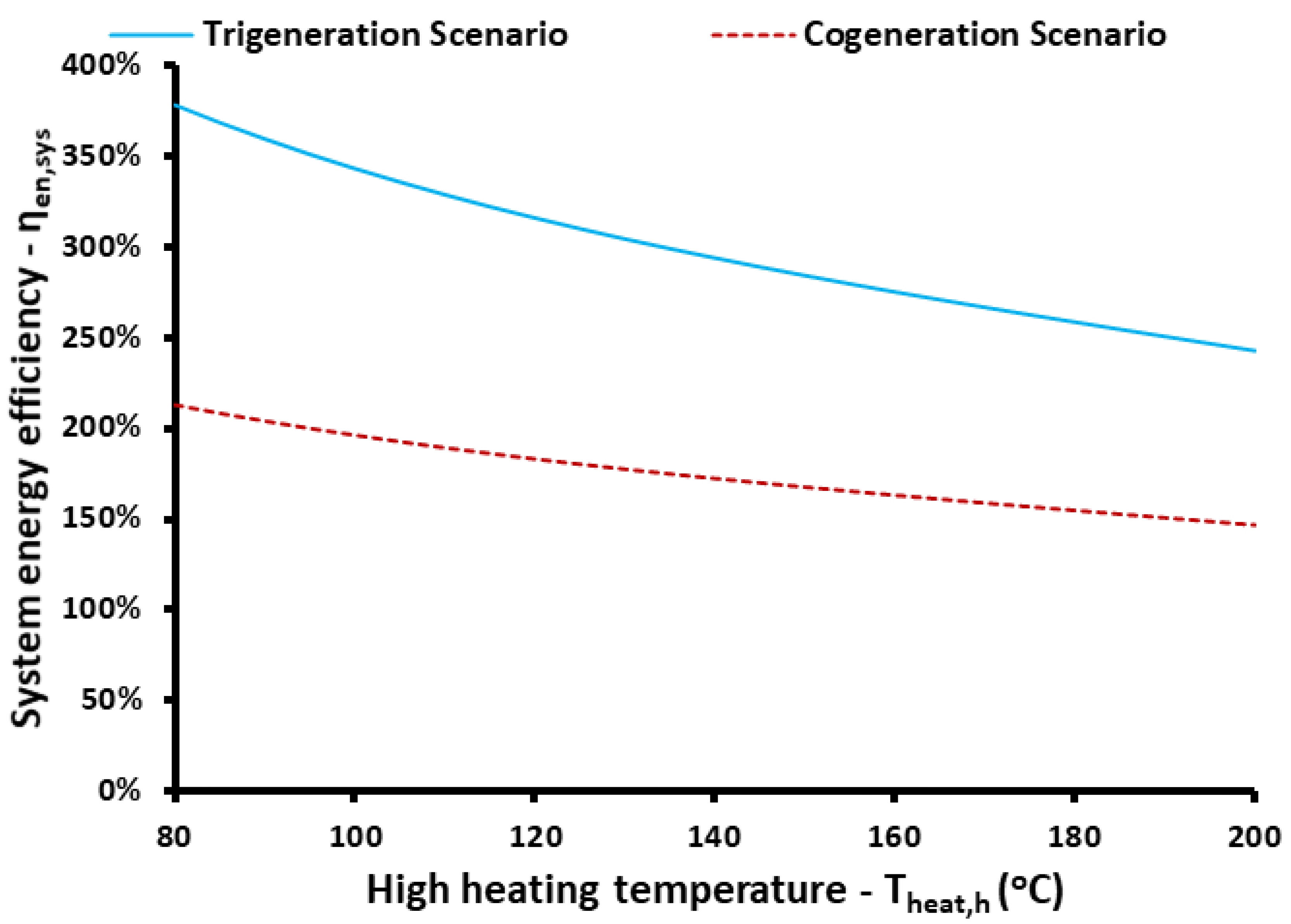
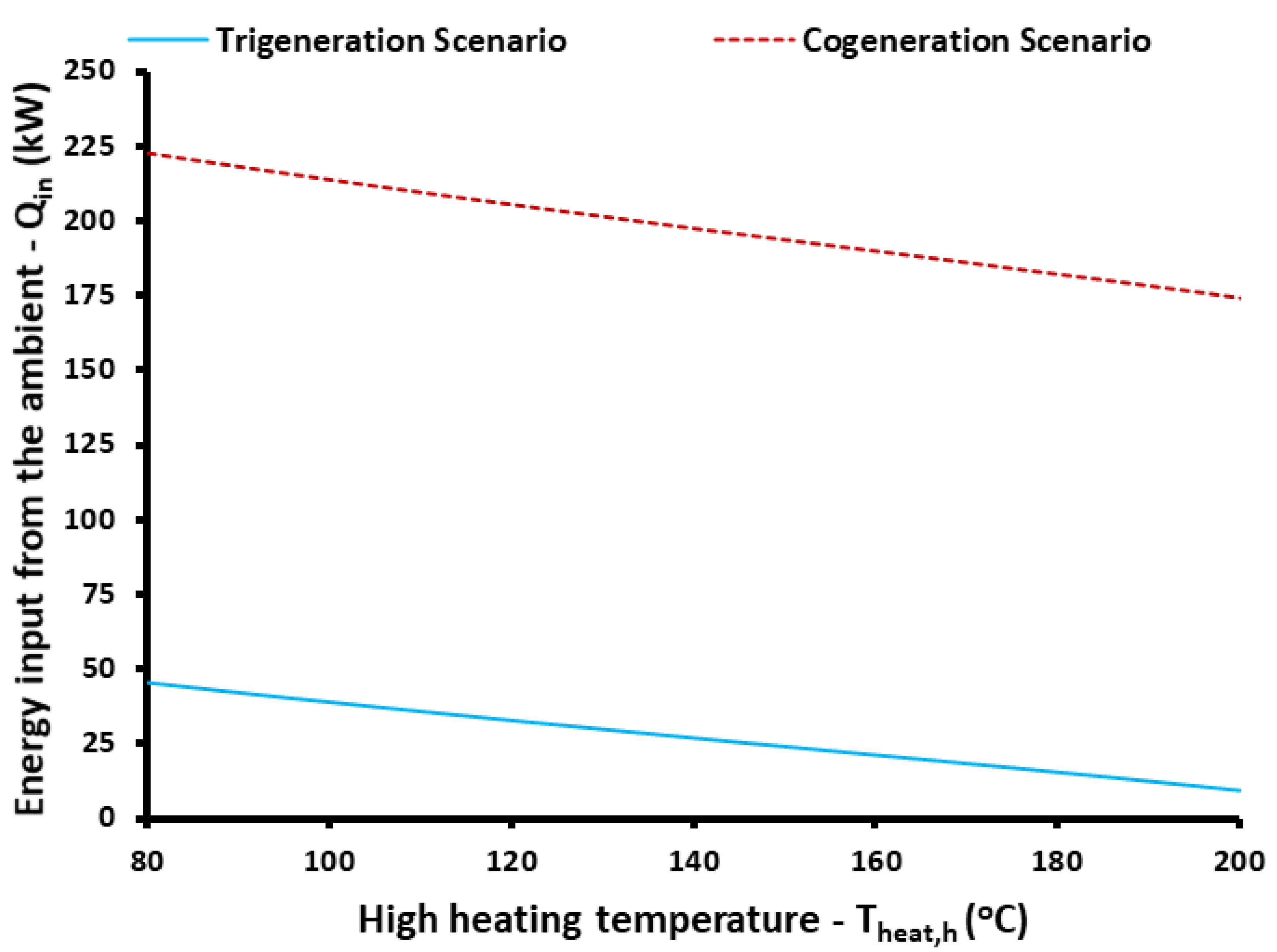
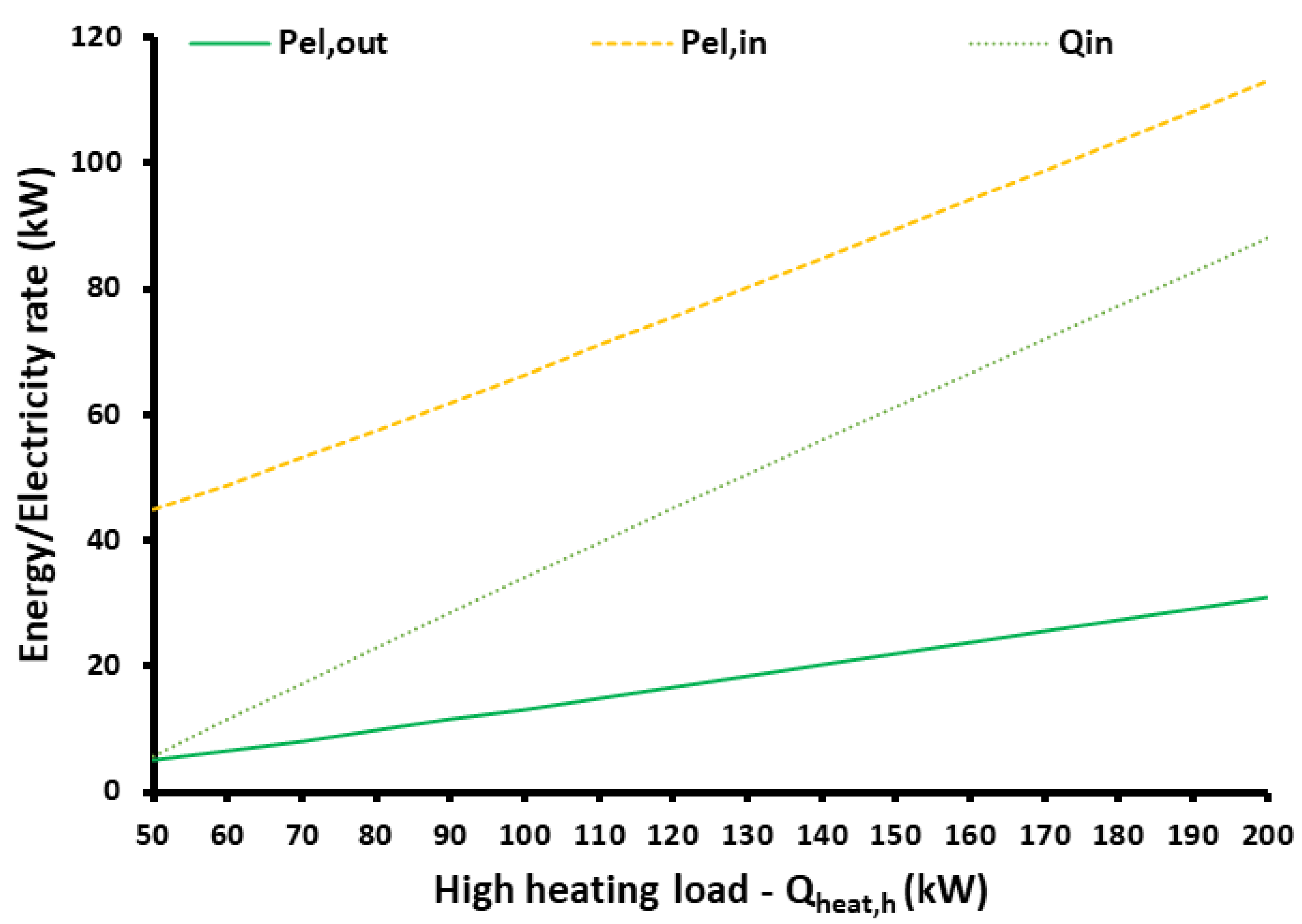
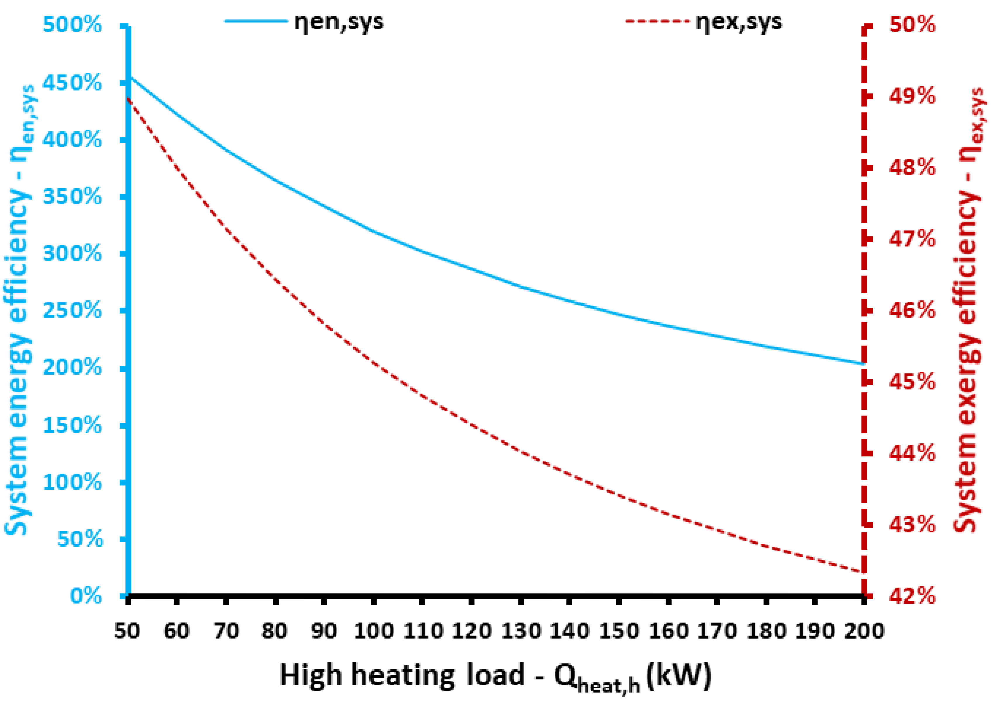
3.1. The Influence of High Heating Temperature on the Results

The first examined parameter is the high heating temperature, which is a critical design parameter. Very high temperatures (above 130 °C) lead to manufacturing restrictions and increased costs. However, according to Figure 4, the increase of this parameter increases electricity production from the ORC for both scenarios (trigeneration and cogeneration). This is a reasonable result in accordance with the “Carnot rule”, which indicates that greater cycle temperature leads to higher cycle thermodynamic efficiency. Figure 5 also validates the aforementioned analysis.
Recall that the data about the trigeneration and cogeneration scenarios appear in Table 1. The ORC performance is higher for the cogeneration scenario because of the lower ambient temperature for this case (winter with Tam = 10 °C). It is worthwhile mentioning that when the high heating temperature increases from 80 °C to 200 °C, the ORC efficiency increases from 7.47% to 21.90% for the trigeneration scenario and from 10.46% to 23.99% for the cogeneration scenario.
The next studied parameter is the system exergy efficiency, shown in Figure 6. The exergy efficiency of the trigeneration scenario is maximized for Theat,h = 115 °C at 45.28%, while for the cogeneration scenario, it is maximized for Theat,h = 125 °C at 45.17%. The global maximum exergy performance of the trigeneration scenario is greater than the respective value of the cogeneration because there is better exploitation of the input electricity when there are three useful outputs. Moreover, it can be said that for temperature levels up to 135 °C, trigeneration has higher exergy efficiency, but after this limit, the cogeneration scenario is more efficient.
Figure 7 depicts the system energy efficiency for both of the examined scenarios. The energy efficiency of the system takes values above 100% because the present system acts, partially, as a heat pump and thus it is thermodynamically possible to achieve these high values. The trigeneration unit has greater energy efficiency than the cogeneration system because in the trigeneration system there are more useful products. Moreover, it is significant to state that a higher high heating temperature reduces energy efficiency, suggesting that the operation should use relatively low-temperature levels from an energy point of view. Specifically, the energetic efficiency ranged from 242.58% to 378.29% for the trigeneration case, while it varied from 146.72% to 213.09% for the cogeneration case.
The next investigated parameter is the heat input in the unit from the ambient. This heat input plays a significant role in the system in order to counterbalance the load demand for heating (medium and high). Figure 8 illustrates the influence of high heating temperature on the ambient heat input; it is obvious that higher temperatures lead to a lower need for ambient energy input. This is an interesting result and shows that in cases with lower high heating temperatures, the ambient has an important role in the system’s performance. On the other hand, in cases of high operating temperature levels, the ambient cannot be an important source for the system and the electricity input is increased. Moreover, the cogeneration case needs higher amounts of ambient source input than the trigeneration case because trigeneration also takes input from the cold loads. The ambient source heat input ranged from 9.44 kW to 45.70 kW for the trigeneration case, while it varied from 174.50 kW to 223.00 kW for the cogeneration case.
At the end of the present subsection, Table 3 summarizes the details of the system for optimum operation according to the exergetic analysis. Practically, for each scenario, the optimum high heating temperature is selected in order to maximize exergetic efficiency, an indicator that properly evaluates all of the useful products.

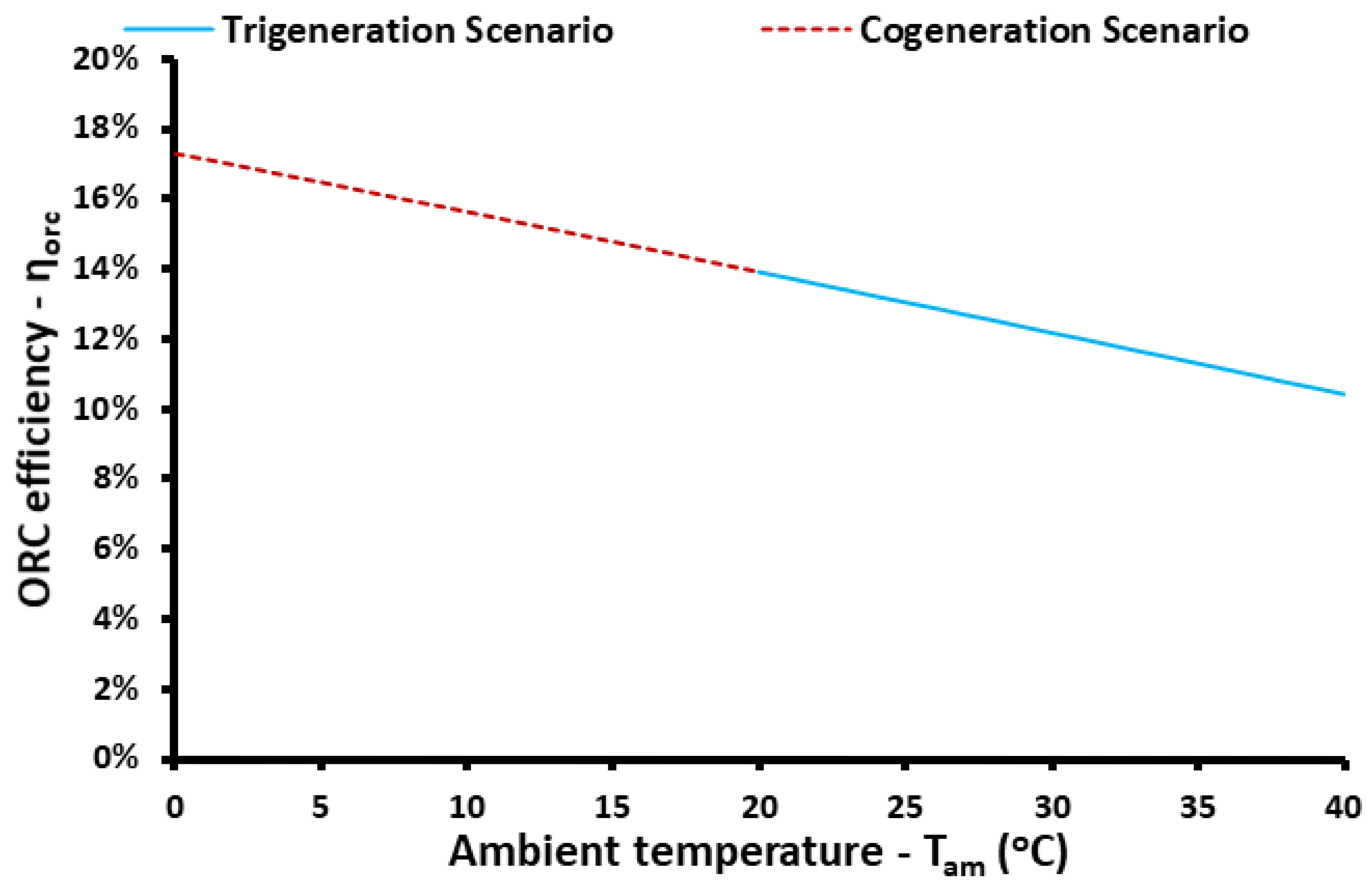
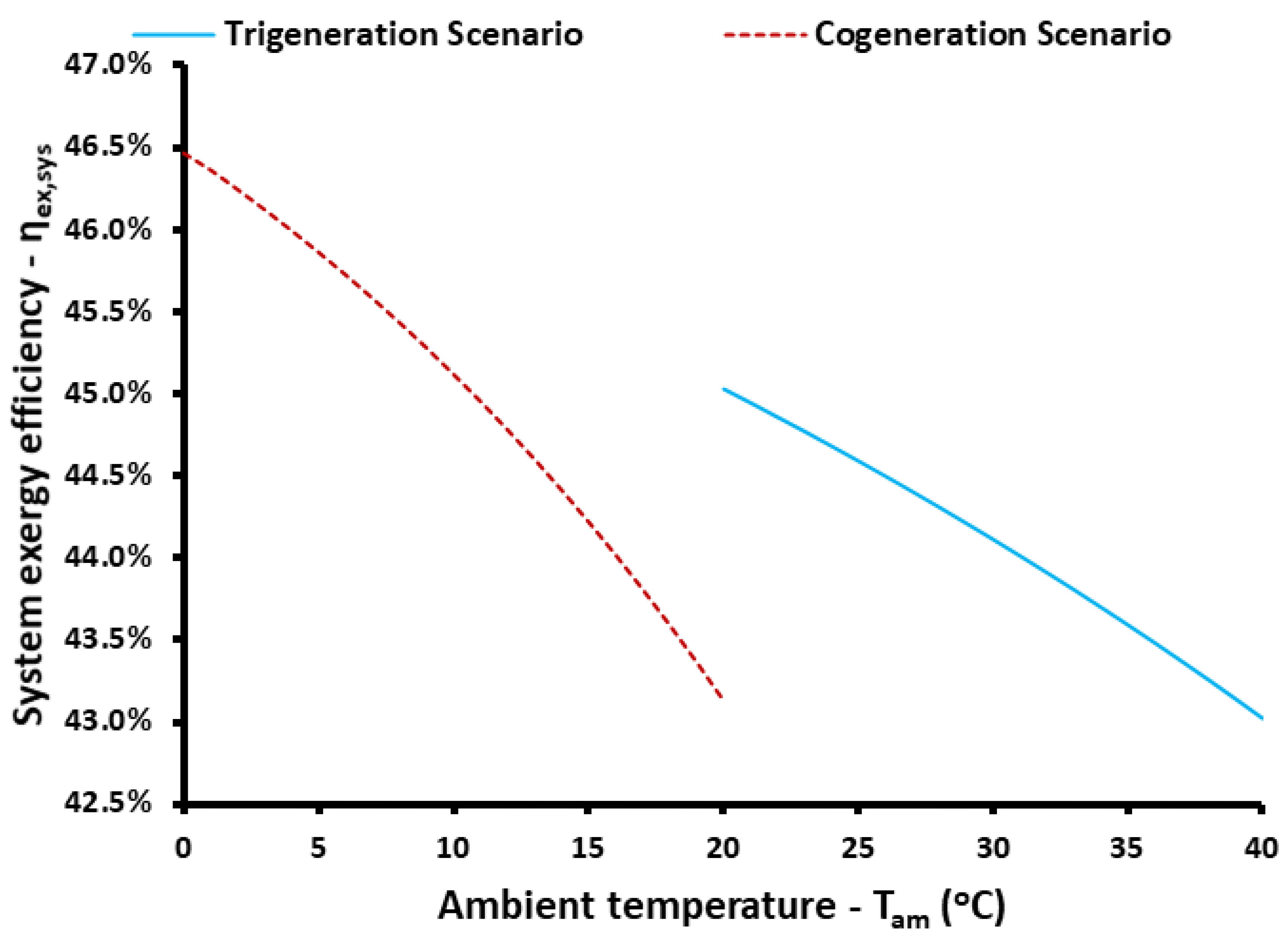
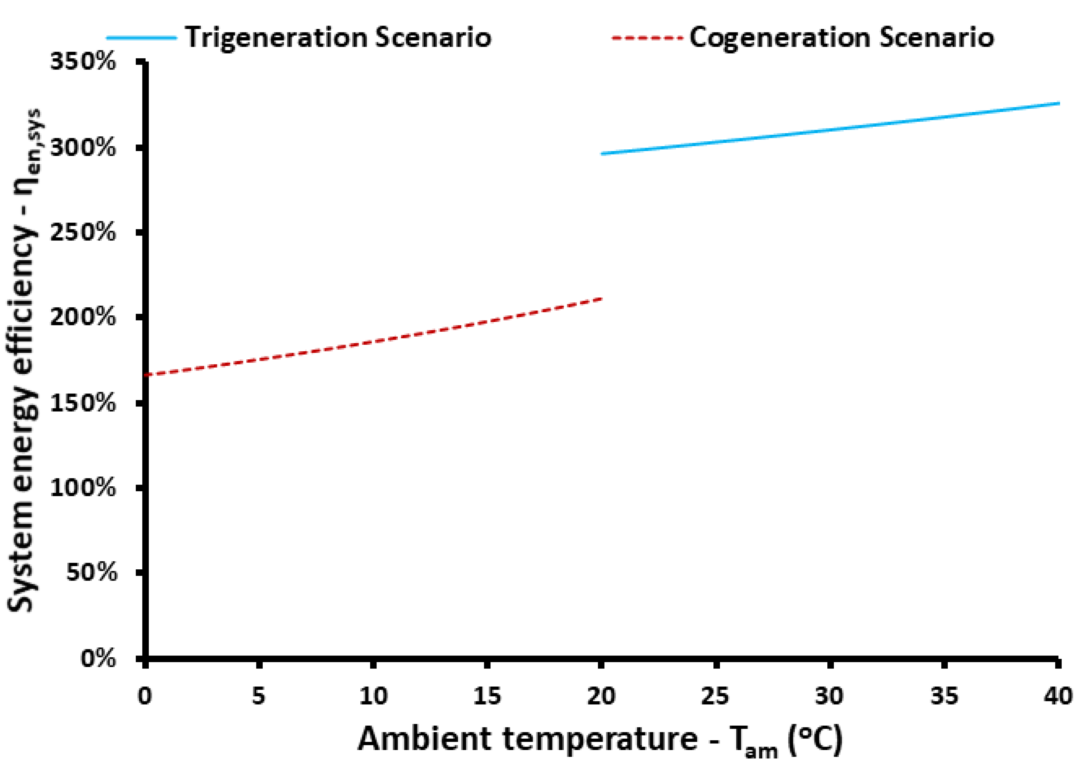
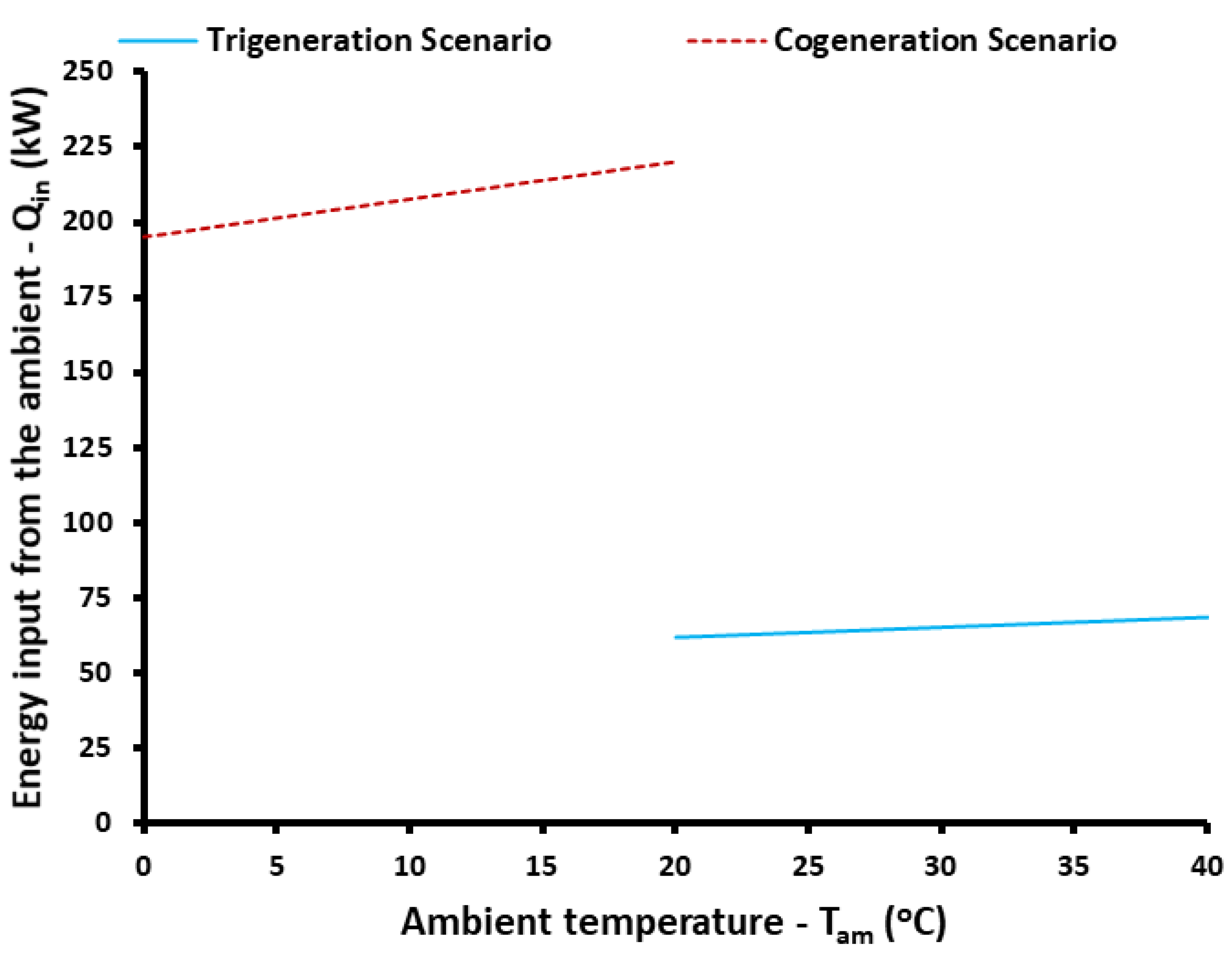
3.2. The Influence of Ambient Temperature Level on the Results

The present section aims to provide information about the influence of the ambient temperature on the unit performance. The ambient temperature is studied in the range from 0 °C to 40 °C, with the assumption that the cogeneration scenario concerns cases with ambient temperatures up to 20 °C and the trigeneration scenario concerns ambient temperatures above 20 °C. This is a valid assumption because the cogeneration design is appropriate for winter, while trigeneration is suitable for summer when there are greater cooling needs. In this section’s analysis, the high heating temperature is selected at (Theat,h = 115 °C), which is a reasonable value according to the Section 3.1 analysis.
Figure 9 depicts the electricity production from the ORC, while Figure 10 shows the respective thermodynamic efficiency of the cycle. Higher ambient temperature reduces both the electricity production and the efficiency, reasonable results which are justified by the decrease in the turbine expansion ratio due to the higher condenser temperature. The cogeneration scenario has high-temperature heat input at 150 kW, while the trigeneration scenario is at 100 kW, justifying the higher electricity recovery from the ORC. Figure 10 shows that the efficiency of the ORC is approximately a linear function of the ambient temperature.
The next studied parameter is the exergetic efficiency for the studied cases and for different ambient temperatures. Figure 11 illustrates the exergy performance of the system; it is obvious that the rise of the ambient temperature reduces the exergy performance of the studied configuration. For the cogeneration scenario, the exergy efficiency ranged from 43.13% to 46.47%, while for the trigeneration scenario the range was from 43.03% to 45.03%. Figure 12 exhibits the system energy efficiency for the respective cases. The higher ambient temperature leads to higher performance, a result that contrasts the findings of the exergy efficiency. This result is a reasonable result because the present system operates mainly as a heating heat pump because it takes heat from the ambient and thus higher ambient temperature levels makes the intermediate compressor to consume lower amounts of electric power. In the trigeneration scenario, the energy efficiency ranged from 296.40% to 325.84%, while the cogeneration scenario range was from 166.51% to 211.74%. These values are greater than 100% because the system works mainly as a heat pump which is not restricted by the limit of 100%.
The last examined parameter in this section is the heat input from the ambient to the system. Figure 13 depicts the heat quantities that the system absorbs from the ambient in order to produce the heating products. Higher ambient temperature levels cause the heat input in the system to be higher, a reasonable result in accordance with the aforementioned analysis. The heat input in the system is greater for the cogeneration scenario compared to the trigeneration scenario because in the trigeneration case there is also input in the system from the cooling production. In the cogeneration case, the heat input from the ambient ranged from 195.4 kW to 220.1 kW, while for the trigeneration scenario the range was from 61.90 kW to 68.67 kW. It is obvious that the ambient temperature variation has not an important influence on this parameter, while the examined case (cogeneration or trigeneration) has a significant impact on this one.

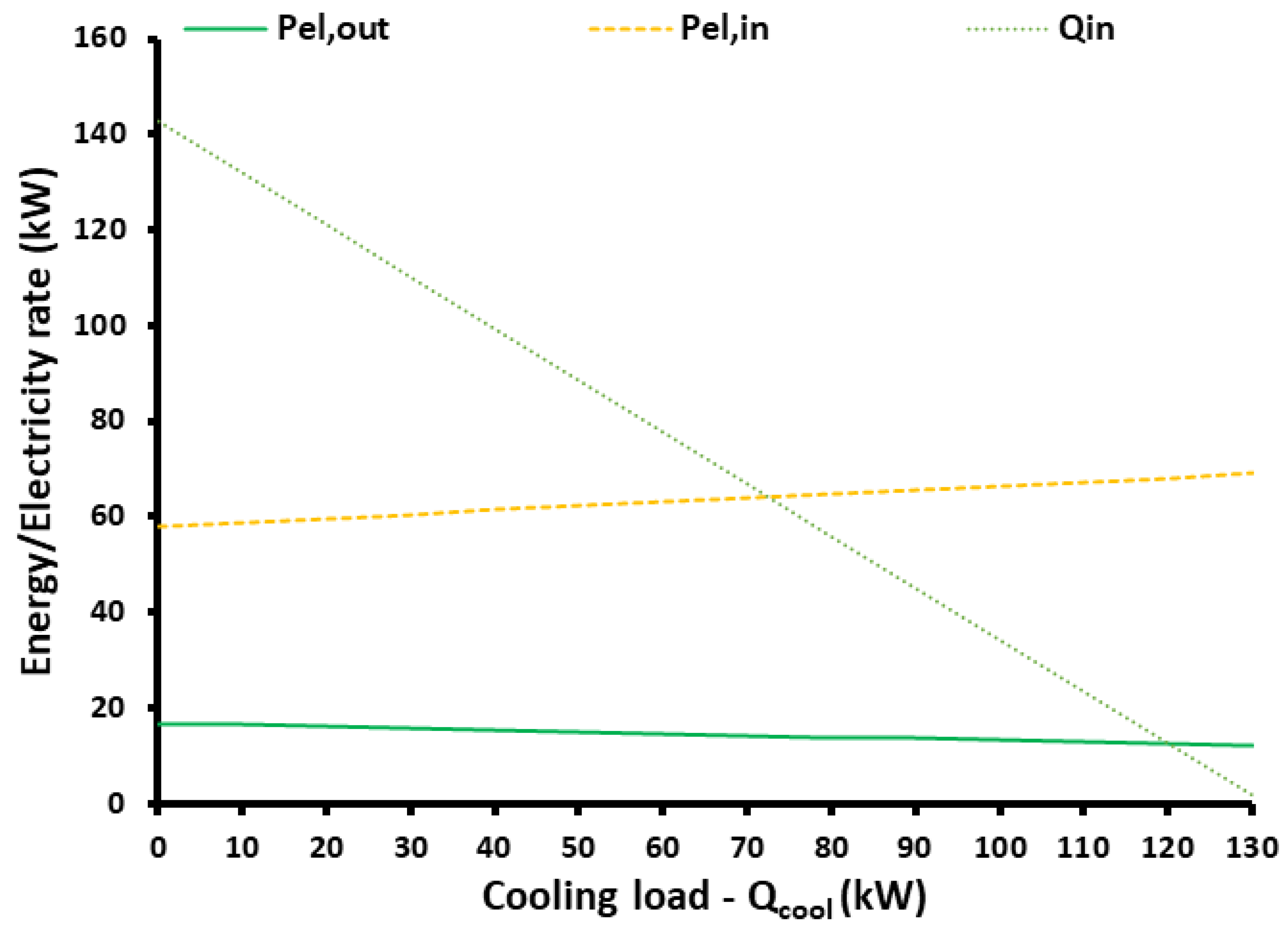
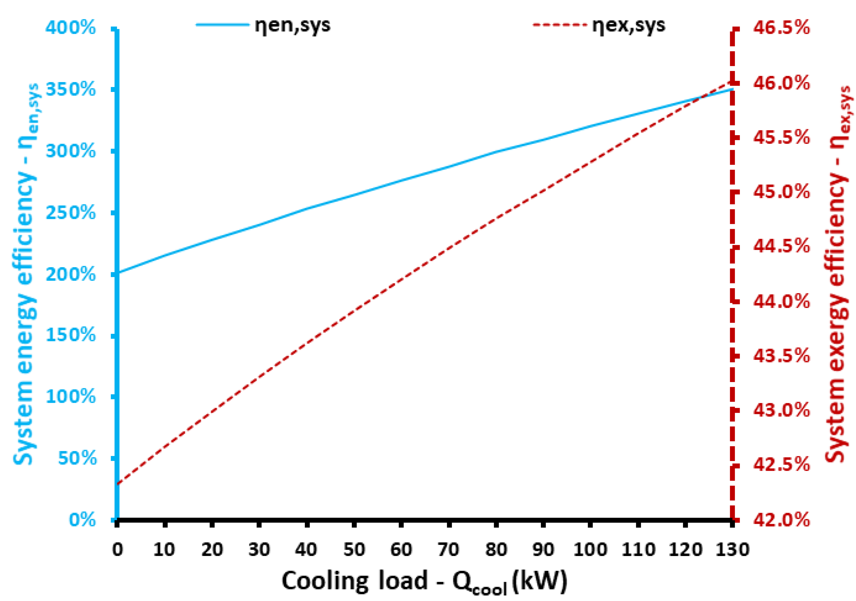
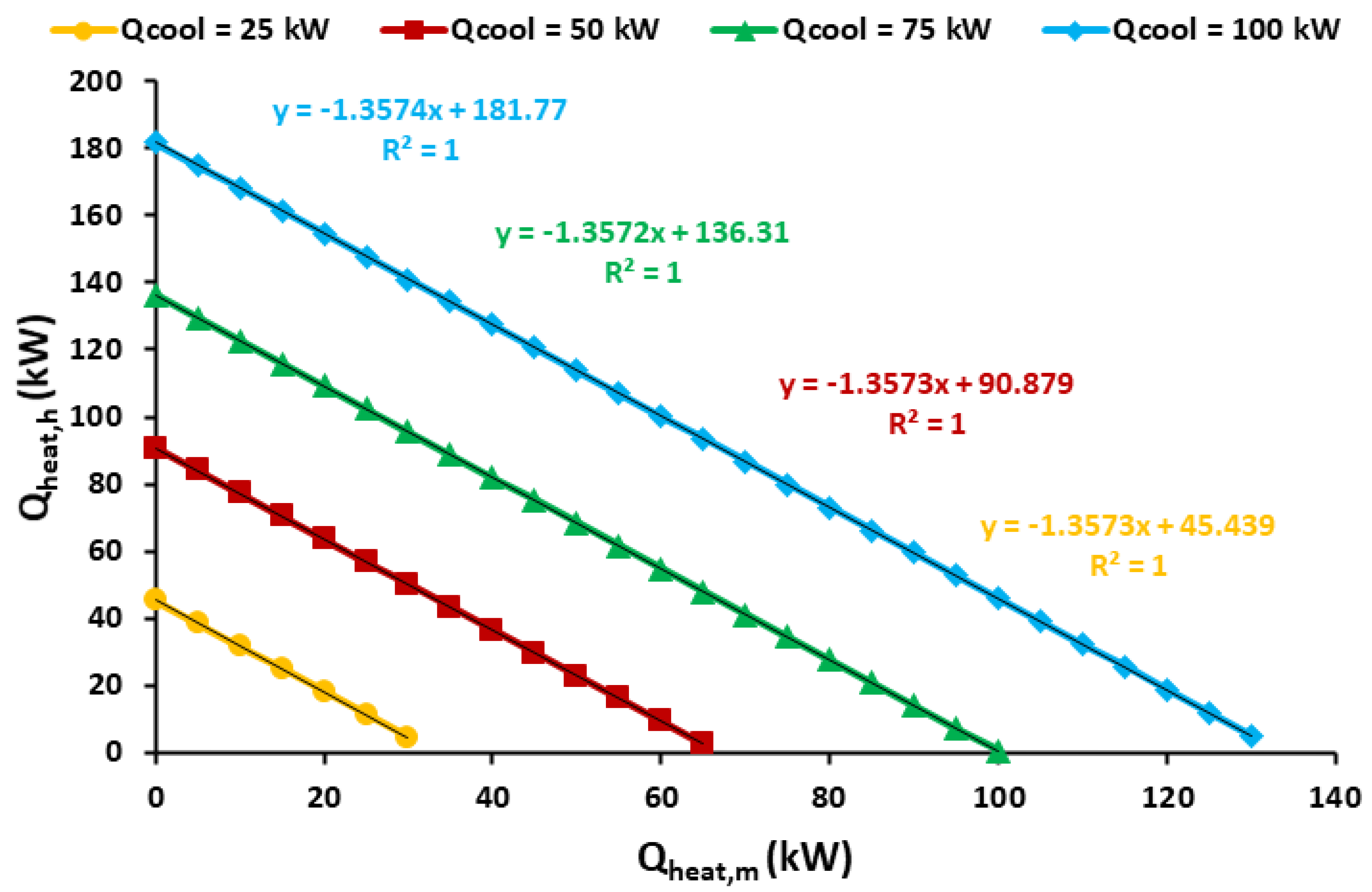
3.3. The Influence of Loads on the Results

The next stage in this analysis is the study of the different design scenarios in order to check the unit performance for different load demands. Figure 14 illustrate the performance of the system when the cooling and heating loads are varied. Each time, only one parameter changes while the others are kept at their default values. The trigeneration scenario is studied, which means that all loads are equal to 100 kW (see Table 1). The ambient temperature is 25 °C, while the high heating temperature is variable. More specifically, in each case, the (Theat,h) is optimized in order to maximize the system exergy efficiency. This simple optimization is conducted with the EES by using the “Golden Section Research” method which is supported by the same software. The relative tolerance was chosen at 10−6 and the maximum function calls at 1000.
Figure 14 and Figure 15 show the impact of the cooling loads on the results. Specifically, Figure 14 depicts the influence of this load on the input electricity, output electricity and heat input in the system. Higher cooling load needs greater electricity consumption which is an acceptable result thermodynamically. The electricity production and ambient heat input decrease with the cooling load increase because the optimum high heating temperature also decreases. It is useful to set the optimum high heating temperature at 144.5 °C for zero cooling load and 108.5 °C for a cooling load of 130 kW. According to Figure 15, both energy and exergy efficiencies increase with the augmentation of the cooling load. For zero cooling load (a cogeneration case), the energetic efficiency was 201.61% and the exergetic efficiency was 42.33%. For the case with the maximum cooling load of 130 kW, the energy and the exergy efficiencies were 350.81% and 46.03%, respectively.
The next step is the investigation of the medium temperature heating production (or space-heating production) on the results. Figure 16 shows that higher space-heating demand increases the need for electricity input, as well as the heat input from the ambient. On the other hand, electricity production from the ORC presents a slight reduction due to the small variation of the optimum high heating temperature. Specifically, for space heating at 70 kW, the optimum high heating temperature is 116.6 °C, while for space heating at 200 kW it is 12.8 °C. Figure 17 indicates that both energy and exergy efficiencies increase with the augmentation of the space-heating demand. In this case, the energy efficiency ranged from 29.68% to 394.22%, while the exergy efficiency ranged from 44.47% to 47.13%.
Figure 18 and Figure 19 illustrate the influence of the high-temperature load on the unit behavior. According to Figure 18, the increase in high heating production leads to input electricity, produced electricity and heat input from the ambient to be increased. The optimum high heating temperature is found at 95.8 °C for Qheat,h = 50 kW and at 133.5 °C for Qheat,h = 200 kW. Figure 19 indicates that both energy and exergy efficiencies have a decreasing rate when higher amounts of heating are stored at the high-temperature level. This shows the need to store only the redundant quantities of energy in the high-temperature levels and not to design the high storage temperature level in high capacity. Specifically, the energy efficiency ranged between 204.39% and 456.95%, while the exergy efficiency ranged between 42.34% and 48.98%.

3.4. Operating Limits of the Examined System

The examined system is able to operate with different combinations of loads, as was shown in Section 3.3. However, it is not possible to operate with all the possible operating scenarios due to energy balance restrictions. Specifically, the ambient source heat input acts as the counterbalance energy rate in order to provide the proper heating loads. This heat input (Qin) cannot be negative and this is a restriction of the present design.
Figure 20 shows different operating lines of the system, with each corresponding to a different cooling load. Cooling loads of 25 kW, 50 kW, 75 kW and 100 kW are examined and in all cases, the operating lines are approximately vertical. In this analysis, Tam = 25 °C and Theat,h = 115 °C, with this combination used in the majority of cases of this work.
Moreover, Figure 20 proves that the linear correlation of each curve separately is very accurate with R2 = 1. The next step is the development of an overall equation for determining the system operating limits. This equation is:
Q h e a t , h 1.8176 Q c o o l 1.3573 Q h e a t , m
The aforementioned equation has R2 = 0.9999 and a mean absolute deviation error of 0.02%; thus, it is a very accurate formula. The equation has been developed for zero ambient source heat input. Therefore, it is a low limit because higher ambient heat input gives a greater possibility for heating production.

4. Conclusions

The goal of this paper was the thermodynamic analysis of a thermal-pumped storage system for trigeneration. The basic idea was to exploit volatile electricity from renewables in order to produce cold storage for cooling, medium thermal storage for space heating and high-temperature thermal storage for utilization in an ORC for electricity recovery. The present work used a thermodynamic approach that aimed to present the present idea and to determine its performance. The following points summarize the most significant conclusions of the simulation study:
-
The exergy efficiency of the trigeneration scenario was maximized for Theat,h = 115 °C at 45.28%, while for the cogeneration scenario it was maximized for Theat,h = 125 °C at 45.17%.
-
The energy efficiency ranged from 242.58% to 378.29% for the trigeneration case, while it varied from 146.72% to 213.09% for the cogeneration case.
-
The increase of the ambient temperature reduced the system exergy efficiency while leading to higher system energy efficiency.
-
The increase of the cooling load and of the space heat load led to higher energy and exergy efficiencies. However, the augmentation of the high heating temperature reduced both energy and exergy efficiencies.
-
It was found that the high heating temperature storage must exceed a minimum limit and it is preferable, thermodynamically, for it not to be designed in a very high capacity in order to have high energy and exergy efficiency rates.
In the future, the proposed configuration will be investigated in detail by placing emphasis on the storage system and the determination of the storage tank volumes, as well as on the selection of the proper phase change materials. Moreover, it is important to examine this system coupled to an application (e.g., a building). Lastly, this system has to be examined experimentally in order to check the long-term performance of the unit under real conditions.

Author Contributions

E.B.: Conceptualization, investigation, software, methodology, writing and reviewing the original paper; P.L.: software, methodology, writing and reviewing the original paper; C.T.: software, supervision, writing and reviewing the original paper. All authors have read and agreed to the published version of the manuscript.

Funding

This research received no external funding.

Institutional Review Board Statement

Not applicable.

Informed Consent Statement

Not applicable.

Data Availability Statement

Data available after request.

Conflicts of Interest

The authors declare no conflict of interest.

Nomenclature

hFluid specific enthalpy, kJ/kg
mFluid mass flow rate, kg/s
PelElectric power, kW
Pel,inInput electric power in the system, kW
Pel,outOutput electric power from the organic Rankine cycle, kW
PPPinch point, K
QHeat rate, kW
QinInput heat rate in the unit from the ambient, kW
TTemperature, °C
XUseful energy quantity from electricity conversion, kW
YUseful energy quantity from electricity conversion, kW
ZUseful energy quantity from electricity conversion, kW
Greek Symbols
ΔΤTemperature difference, K
ηen,sysEnergy efficiency of the unit
ηex,sysExergy efficiency of the unit
ηisIsentropic efficiency of the compressor
ηis,pOrganic fluid pump isentropic efficiency
ηis,tIsentropic efficiency of the turbine
ηmMechanical efficiency
ηmgElectromechanical efficiency
ηmotorMotor-pump efficiency
ηorcThermodynamic efficiency of the organic Rankine cycle
Subscripts and Superscripts
aCompressor (a)
amAmbient
bCompressor (b)
cCompressor (c)
coolCooling
isIsentropic
in-amInside ambient
lowLow
HEXHeat exchanger
heatHeating
heat, hHeating at high-temperature level
heat, mHeating at medium temperature level
HRSHeat recovery system
highHigh
optOptimum
orcOrganic Rankine cycle
recRecuperator
satSaturation
Abbreviations
EESEngineering Equation Solver
HEXHeat Exchanger
HPHeat Pump
HRSHeat Recovery System
ORCOrganic Rankine Cycle
PCMPhase Change Material

References

  1. Alemany, J.M.; Arendarski, B.; Lombardi, P.; Komarnicki, P. Accentuating the renewable energy exploitation: Evaluation of flexibility options. Int. J. Electr. Power Energy Syst. 2018, 102, 131–151. [Google Scholar] [CrossRef]
  2. Eitan, A.; Fischhendler, I. The social dimension of renewable energy storage in electricity markets: The role of partnerships. Energy Res. Soc. Sci. 2021, 76, 102072. [Google Scholar] [CrossRef]
  3. Dreißigacker, V.; Belik, S. System Configurations and Operational Concepts for Highly Efficient Utilization of Power-to-Heat in A-CAES. Appl. Sci. 2019, 9, 1317. [Google Scholar] [CrossRef] [Green Version]
  4. Frate, G.F.; Ferrari, L.; Desideri, U. Rankine Carnot Batteries with the Integration of Thermal Energy Sources: A Review. Energies 2020, 13, 4766. [Google Scholar] [CrossRef]
  5. Dumont, O.; Frate, G.F.; Pillai, A.; Lecompte, S.; de Paepe, M.; Lemort, V. Carnot battery technology: A state-of-the-art review. J. Energy Storage 2020, 32, 101756. [Google Scholar] [CrossRef]
  6. Eppinger, B.; Muradi, M.; Scharrer, D.; Zigan, L.; Bazan, P.; German, R.; Will, S. Simulation of the Part Load Behavior of Combined Heat Pump-Organic Rankine Cycle Systems. Energies 2021, 14, 3870. [Google Scholar] [CrossRef]
  7. McTigue, J.D.; Farres-Antunez, P.; Sundarnath, K.J.; Markides, C.N.; White, A.J. Techno-economic analysis of recuperated Joule-Brayton pumped thermal energy storage. Energy Convers. Manag. 2021, 252, 115016. [Google Scholar] [CrossRef]
  8. Eppinger, B.; Zigan, L.; Karl, J.; Will, S. Pumped thermal energy storage with heat pump-ORC-systems: Comparison of latent and sensible thermal storages for various fluids. Appl. Energy 2020, 280, 115940. [Google Scholar] [CrossRef]
  9. Zamengo, M.; Yoshida, K.; Morikawa, J. Numerical evaluation of a Carnot battery system comprising a chemical heat storage/pump and a Brayton cycle. J. Energy Storage 2021, 41, 102955. [Google Scholar] [CrossRef]
  10. Steinmann, W.; Jockenhöfer, H.; Bauer, D. Thermodynamic Analysis of High-Temperature Carnot Battery Concepts. Energy Technolology 2020, 8, 1900895. [Google Scholar] [CrossRef] [Green Version]
  11. Bellos, E.; Tzivanidis, C.; Said, Z. Investigation and optimization of a solar-assisted pumped thermal energy storage system with flat plate collectors. Energy Convers. Manag. 2021, 237, 114137. [Google Scholar] [CrossRef]
  12. Dumont, O.; Lemort, V. Mapping of performance of pumped thermal energy storage (Carnot battery) using waste heat recovery. Energy 2020, 211, 118963. [Google Scholar] [CrossRef]
  13. Ayachi, F.; Tauveron, N.; Tartière, T.; Colasson, S.; Nguyen, D. Thermo-Electric Energy Storage involving CO2 transcritical cycles and ground heat storage. Appl. Therm. Eng. 2016, 108, 1418–1428. [Google Scholar] [CrossRef]
  14. Schimpf, S.; Span, R. Techno-economic evaluation of a solar assisted combined heat pump—Organic Rankine Cycle system. Energy Convers. Manag. 2015, 94, 430–437. [Google Scholar] [CrossRef]
  15. Mateu-Royo, C.; Mota-Babiloni, A.; Navarro-Esbrí, J.; Peris, B.; Molés, F.; Amat-Albuixech, M. Multi-objective optimization of a novel reversible High-Temperature Heat Pump-Organic Rankine Cycle (HTHP-ORC) for industrial low-grade waste heat recovery. Energy Convers. Manag. 2019, 197, 111908. [Google Scholar] [CrossRef]
  16. Borissova, A.; Popov, D. An option for integration of Carnot Battery into a small Nuclear Power Plant. E3S Web Conf. 2020, 207, 01027. [Google Scholar] [CrossRef]
  17. Scharrer, D.; Eppinger, B.; Schmitt, P.; Zenk, J.; Bazan, P.; Karl, J.; Will, S.; Pruckner, M.; German, R. Life Cycle Assessment of a Reversible Heat Pump–Organic Rankine Cycle–Heat Storage System with Geothermal Heat Supply. Energies 2020, 13, 3253. [Google Scholar] [CrossRef]
  18. Baccoli, R.; Mastino, C.; Rodriguez, G. Energy and exergy analysis of a geothermal heat pump air conditioning system. Appl. Therm. Eng. 2015, 86, 333–347. [Google Scholar] [CrossRef]
  19. Kasaeian, A.; Bellos, E.; Shamaeizadeh, A.; Tzivanidis, C. Solar-driven polygeneration systems: Recent progress and outlook. Appl. Energy 2020, 264, 114764. [Google Scholar] [CrossRef]
  20. F-Chart Software, Engineering Equation Solver (EES). 2015. Available online: http://www.fchart.com/ees (accessed on 15 December 2021).
Figure 1. A general description of the “Power to XYZ” concept.
Applsci 12 00970 g001
Figure 2. Detailed description of the examined configuration of the pumped thermal energy storage system for trigeneration.
Applsci 12 00970 g002
Figure 3. The examined organic Rankine Cycle (ORC) with recuperator.
Applsci 12 00970 g003
Figure 4. The impact of high heating temperature on ORC electricity production for both trigeneration and cogeneration scenarios.
Applsci 12 00970 g004
Figure 5. The impact of high heating temperature on ORC efficiency for both trigeneration and cogeneration scenarios.
Applsci 12 00970 g005
Figure 6. The impact of high heating temperature on system exergy efficiency for both trigeneration and cogeneration scenarios.
Applsci 12 00970 g006
Figure 7. The impact of high heating temperature on system energy efficiency for both trigeneration and cogeneration scenarios.
Applsci 12 00970 g007
Figure 8. The impact of high heating temperature on energy input from the ambient for both trigeneration and cogeneration scenarios.
Applsci 12 00970 g008
Figure 9. The impact of ambient temperature on ORC electricity production for both trigeneration and cogeneration scenarios.
Applsci 12 00970 g009
Figure 10. The impact of ambient temperature on ORC efficiency for both trigeneration and cogeneration scenarios.
Applsci 12 00970 g010
Figure 11. The impact of ambient temperature on system exergy efficiency for both trigeneration and cogeneration scenarios.
Applsci 12 00970 g011
Figure 12. The impact of ambient temperature on system energy efficiency for both trigeneration and cogeneration scenarios.
Applsci 12 00970 g012
Figure 13. The impact of ambient temperature on energy input from the ambient for both trigeneration and cogeneration scenarios.
Applsci 12 00970 g013
Figure 14. Ambient energy input and electricity rates for different cooling loads.
Applsci 12 00970 g014
Figure 15. System energy and exergy efficiencies for different cooling loads.
Applsci 12 00970 g015
Figure 16. Ambient energy input and electricity rates for different medium heating loads.
Applsci 12 00970 g016
Figure 17. System energy and exergy efficiencies for different medium heating loads.
Applsci 12 00970 g017
Figure 18. Ambient energy input and electricity rates for different high heating loads.
Applsci 12 00970 g018
Figure 19. System energy and exergy efficiencies for different high heating loads.
Applsci 12 00970 g019
Figure 20. System operation margins for different combinations of cooling loads.
Applsci 12 00970 g020
Table 1. Main parameters of the two scenarios in the thermodynamic simulation.
ParametersScenarios
TrigenerationCogeneration
Qcool (kW)1000
Qheat,m (kW)100150
Qheat,h (kW)100150
Tam (°C)2510
Table 2. Input parameters for the simulation.
ParameterSymbolValue
Heat Pump
Compressor’s isentropic efficiencyηis,C80%
Temperature difference on the HEXΔΤHEX5 K
Temperature differenceΔΤ5 Κ
Shaft mechanical efficiencyηm99%
Low temperatureTlow−5 °C
Input temperature from ambientTin-amTam + ΔΤ = 20 °C
Medium temperatureTmed55 °C
High temperatureThigh120 °C
Storage Systems
Cooling stored temperatureTcoolTlow − ΔΤ = 0 °C
Medium stored temperatureTheat,mTmed − ΔΤ = 50 °C
High stored temperatureTheat,hThigh − ΔΤ = 115 °C
ORC
SuperheatingΔΤsh5 K
Turbine isentropic efficiencyηis,T80%
Pinch pointPP5 K
Pump isentropic efficiencyηis,P85%
Saturation temperatureTsat(Theat,hΤsh-PP) °C
Electromechanical efficiencyηmg97%
Recuperator temperature differenceΔΤrec5 K
Motor-pump efficiencyηmotor80%
Table 3. Summary of the optimum designs for the examined scenarios according to the criterion of exergy efficiency maximization.
ParametersScenarios
TrigenerationCogeneration
Qcool (kW)1000
Qheat,m (kW)100150
Qheat,h (kW)100150
Tam (°C)2510
Theat,h-opt (°C)115125
Pel,in (kW)66.1397.22
Pel,out (kW)13.0525.34
Qin (kW)34.53203.8
ηen,sys322.16%180.35%
ηex,sys45.28%45.17%
ηorc13.05%16.89%
ma (kg/s)0.3420
mb (kg/s)0.45030.6797
mc (kg/s)0.23080.3397
md (kg/s)0.10830.6797
me (kg/s)0.21950.34
mf (kg/s)0.45030.6797
Publisher’s Note: MDPI stays neutral with regard to jurisdictional claims in published maps and institutional affiliations.

