Article

Exergy-Based Thermo-Hydraulic Performance of Roughened Absorber in Solar Air Heater Duct

1
CSIR-Central Building Research Institute Roorkee, Roorkee 247667, India
2
Academy of Scientific and Innovative Research (AcSIR), Ghaziabad 201002, India
3
Mechanical Engineering Department, King Saud University, Riyadh 11421, Saudi Arabia
4
Department of Industrial Engineering, College of Engineering, Prince Sattam Bin Abdulaziz University, Al-Kharj 16273, Saudi Arabia
5
Faculty of Engineering, University of Rijeka, 51000 Rijeka, Croatia
6
Department of Mechanical Engineering, Gautam Buddha University, Greater Noida 201312, India
*
Author to whom correspondence should be addressed.
Appl. Sci. 2022, 12(3), 1696; https://doi.org/10.3390/app12031696
Submission received: 8 January 2022 / Revised: 2 February 2022 / Accepted: 4 February 2022 / Published: 7 February 2022
(This article belongs to the Topic Exergy Analysis and Its Applications)

Abstract

:
This paper presents the thermo-hydraulic performance of small conical ribs on the absorber plate of a solar energy air heater (SAH) using exergy analysis. Application of conical protrusion ribs on the absorber is an attractive solution for enhancing the thermal performance of a SAH. However, these ribs are also responsible for high friction losses and increased fan power consumption caused by the turbulent air flow. To optimize the rib design, it is vital to consider both thermal and hydraulic performance at the same time. The SAH was assessed using an analytic method which predicts the exergy efficiency under operating parameters (e.g., Reynolds number, solar insolation and temperature increase parameter). The following geometric quantities of ribs were evaluated for optimum exergy efficiency: the relative rib height (e/D), which was in the range between 0.200 and 0.044, and the relative rib pitch (p/e), which was in the range between 6 and 12. The combination of a relative rib height of 0.044 and relative rib pitch of 10 exhibits the highest exergy efficiency of 0.0202. The optimization of the rib geometric quantities parameters was performed by considering the temperature increase parameter, aiming to achieve maximum exergy efficiency. The combination of rib parameters e/D = 0.044 and p/e = 10 are noted to yield best performance when operating at a temperature increase parameter above 0.0141 K∙m2/W.

1. Introduction

Renewable energy resources are gaining importance due to their eco-friendly nature, zero emissions, elimination of toxic gases, energy supply availability and security. Solar energy is by far the most abundant renewable energy source, with a wide variety of applications, and is available freely. Various techniques for harnessing solar energy are available for applications such as cooking, water distillation, power generation and cooling/heating [1], etc. The solar air heater (SAH) is a thermal system using solar energy to produce hot air. Air heating in a SAH is the simplest way to utilize solar energy, which may be exploited in various air heating applications. The SAH is constructed using the following components: absorber plate, glazing, housing and air blower. The most important component is the absorber plate where solar radiation is converted into thermal energy by heating air. The literature [2,3,4] reports that the performance of SAHs is not expected to develop enough to achieve economic viability in real applications. The reason for this disadvantage is the low heat extraction ability of air, especially when flowing over smooth absorber plates. As a result, research is concentrating on the creation of techniques that are both energy efficient and economically viable. For instance, roughened absorber plates can be used to improve the heat exchange between absorber plate and air flow [5]. Wires can be attached in a variety of ways to achieve surface roughness on the absorber plate: ribs with transverse wires [6,7], angle wire ribs [8], V-shaped wire ribs [9], multi V-shaped ribs [10], discrete V-shaped ribs [11], multi V-shaped ribs with gaps [12], L-shaped ribs [13], multi arc-shaped ribs with gaps [14] and S-shaped ribs with gaps [15]. Heat transfer enhancement by chamfered ribs with grooves [16,17] and rectangular ribs with grooves [18,19] has also been explored. By locally promoting turbulence in the air flow and disrupting the sub-laminar layer on the absorber surface by means of the roughness on the absorber plate, thermal performance can be improved. Heat transfer can be further increased by employing ribs with large height. Large-height ribs create more turbulence in the air flow, but also low circulation regions and hot zones in the vicinity of ribs. The hot zones are suppressed by employing the perforated ribs. Air jets issuing through these perforations strike on the hot zones and promote the flow turbulence. Perforated ribs also reduce the pressure drop significantly [20,21].
The performance of solar air heaters with dimple ribs on the absorber was investigated by Saini and Verma [22]. The following parameters of dimple ribs were employed: a relative rib pitch between 0.018 and 0.037 and relative rib height between 8 and 12. The results revealed that dimple ribs lead to significant heat transfer enhancement without an excessive pressure drop penalty. In a similar manner, Sethi et al. [23,24] investigated the performance of arc-shaped dimple ribs on the absorber using the experimental approach with the following rib parameters: a relative rib height between 0.021 and 0.036, relative rib pitch between 10 and 20 and arc angle between 45° and 75°. The arc-shaped dimple ribs achieved considerable heat transfer enhancement as a result of flow separation, vortex generation and vortex shading in the flow. Another study [25] examined the effects of relative print dia of spherical dimple ribs, relative long way length and relative short way length of the absorber. It was determined that friction factors and Nusselt numbers are more than 2.2 and 3.2 times higher than in conventional smooth surfaces, respectively. Similarly, air mass flow rates were varied in the range between 0.009 and 0.0028 kg/s to analyze the effect on dimple ribs. The increase of air temperature in the air duct with dimple ribs was 4.6 °C compared to a conventional smooth duct with air mass flow of 0.009 kg/s [26]. Semi-spherical protrusion ribs have been exploited to study further the improvement of SAH performance. The effects of relative rib pitch and rib height, as well as the angle of attack, were studied in [27]. In the continuation of a similar work on protrusion ribs, the author of [28] designed a new conical protrusion rib and numerically investigated its performance in terms of friction factors and Nusselt numbers. The conical protrusion ribs were studied for relative rib pitches between 6 and 12 and relative rib heights between 0.020 and 0.044. Sharp corners on the conical ribs created flow turbulence which has a favorable effect in terms of heat transfer enhancement; however, at the expense of a reduced hydraulic performance. Sharma and Kamlakar [29] carried out an intensive review on various types of artificial roughness for a SAH. They pointed out that dimple/protrusion rib roughness was more advantageous compared to other artificial roughness designs. These types of rib roughness offer several advantages: (i) heat transfer enhancement without excessive pressure drop increase, (ii) no additional mass on the absorber plate and (iii) easily manufactured by pressing down on the indenting device.
The literature reveals that the thermo-hydraulic performance of SAHs needs to be considered simultaneously. Thermo-hydraulic performance analysis determines the best design of artificial roughness in various operative conditions. Previously, the authors of [28] presented the thermo-hydraulic efficiency of conical protrusion ribs. This work is a continuation of the previous authors’ work [28], in which the characteristics of exergy efficiency of conical protrusion ribs were presented, and the ribs parameters were optimized. The present study discusses the benefits of exergy analysis for designing the SAH, attributing the maximum gain in useful work. The two main goals of this work are to: (i) investigate the effects of surface roughness on the exergy efficiency and (ii) optimize the protrusion ribs for best exergy efficiency in different temperature increase parameter ranges.

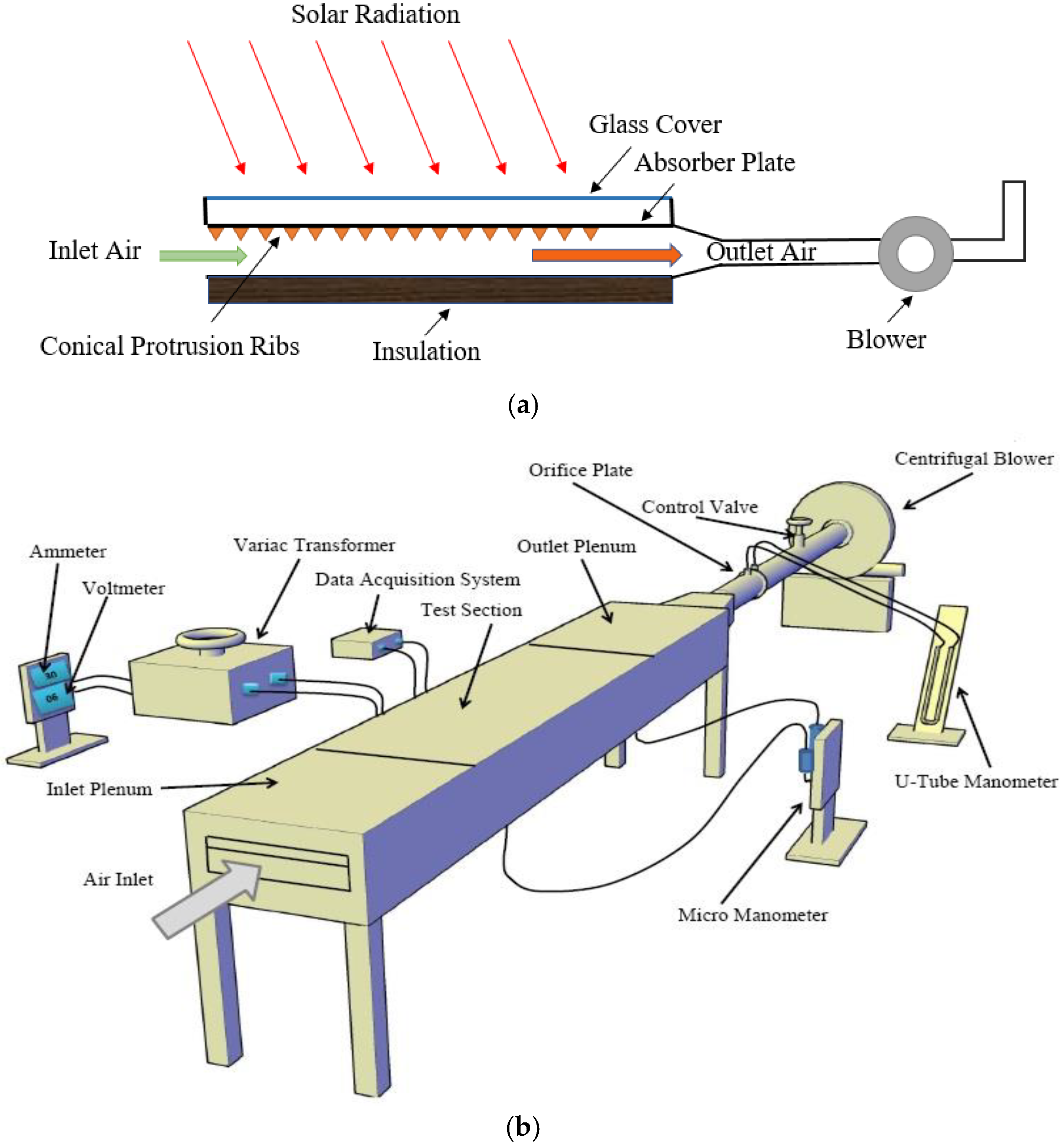
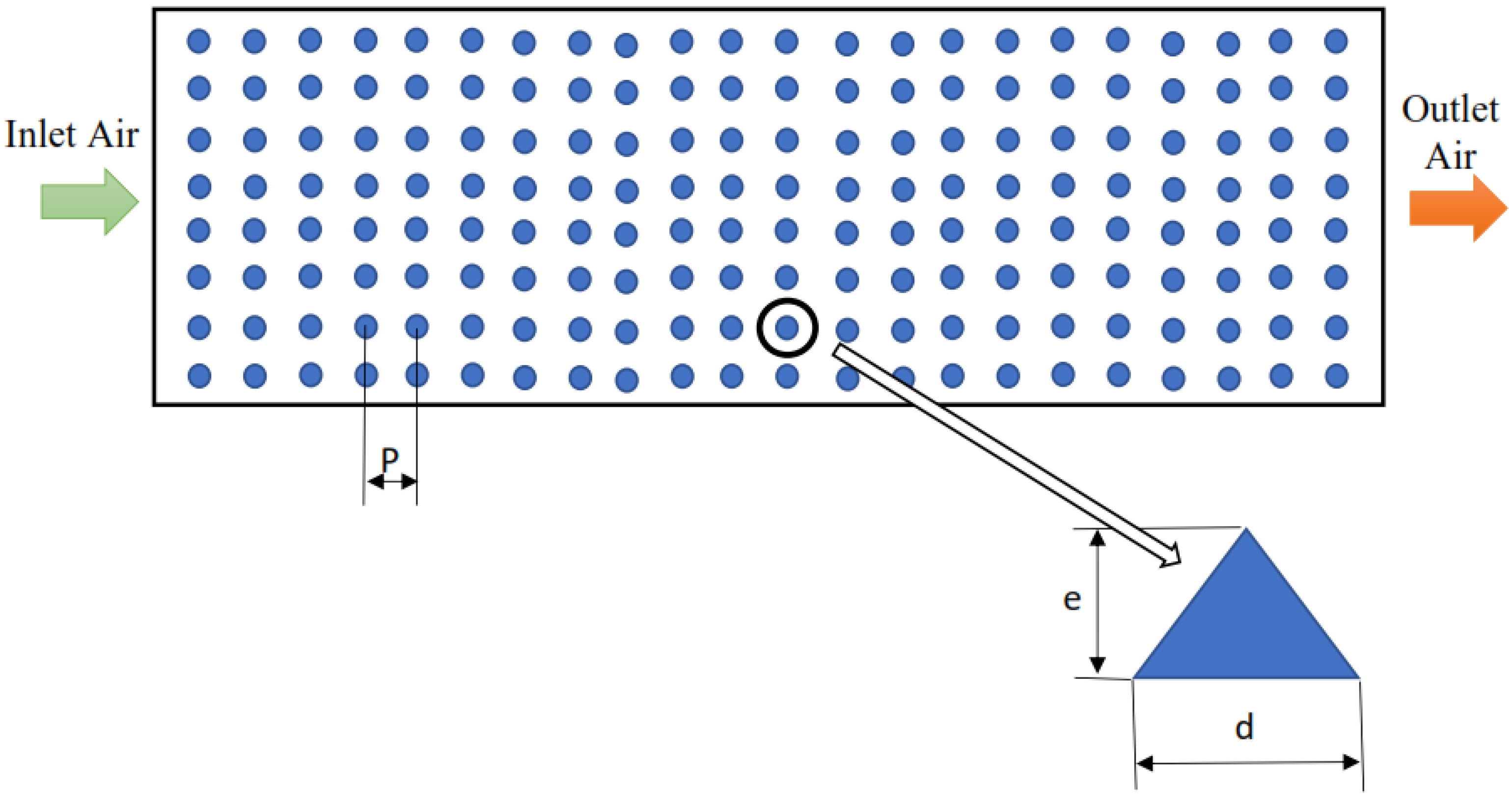
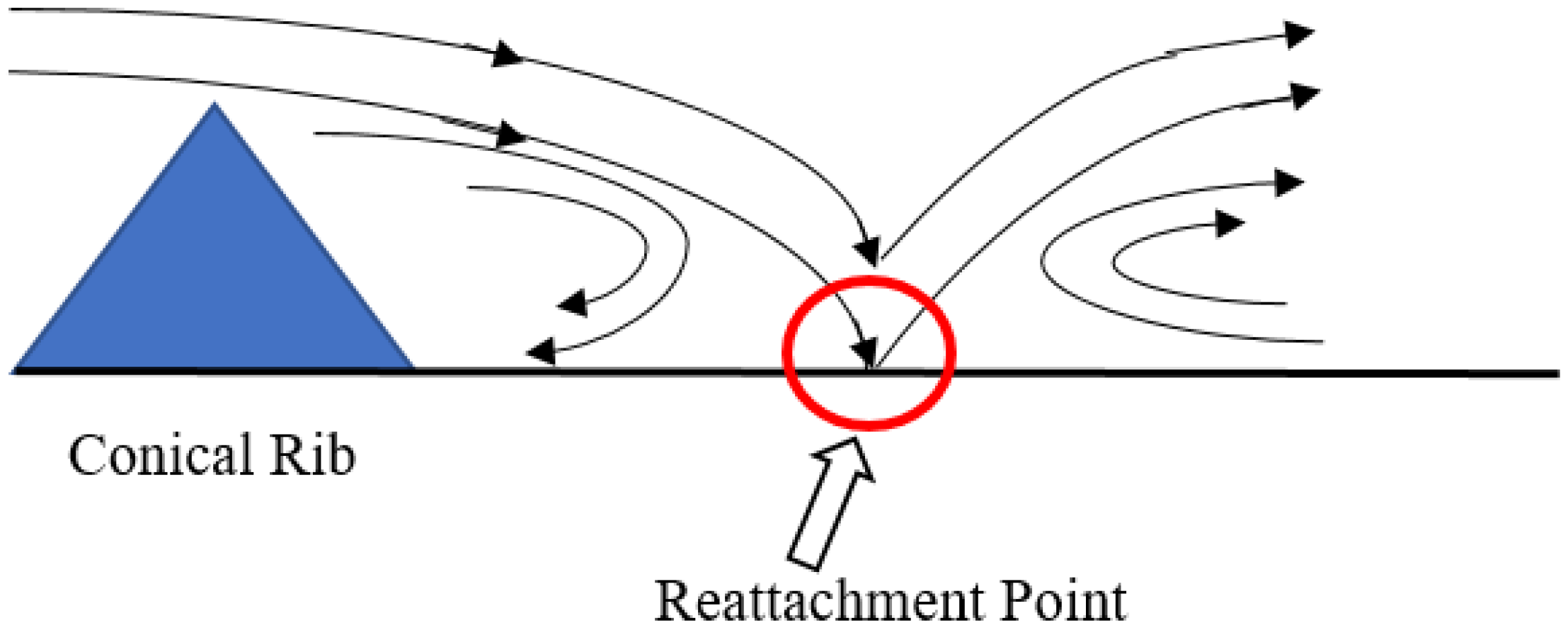
2. Details of SAH Equipped with Conical Protrusion Ribs

A SAH is a solar thermal system converting solar energy into thermal energy by heating air. The design of the SAH is simple and consists of five main components: (i) absorber plate, (ii) glass cover, (iii) housing, (iv) blower and (v) thermal insulation, as shown in Figure 1a. A three-dimensional view of the SAH with various instrumentation is presented in Figure 1b, and details can be found in the literature [20,21].
The absorber plate is considered as the heart of this system. The following major parameters have great influence on the SAH performance: emissivity and absorptivity of the absorber, heat transfer coefficients between absorber and air flow, the solar concentration ratio and the intensity of insolation and thermal losses, especially heat losses from the top cover. In the authors’ previous work [30], the conical protrusion ribs were employed to enhance heat exchange between the absorber plate and air flow, as shown in Figure 1.
The conical protrusion ribs’ parameters, such as relative rib pitch and relative rib height, were analyzed in terms of Nusselt number, friction factor and thermal efficiency. The details of the SAH and the roughness obtained with conical protrusion ribs were given and discussed in the authors’ previously published paper [28]. The configuration of the conical ribs is shown in Figure 2. The sharp corners on the conical ribs affected the air flow, which, in turn, affected the friction factor and Nusselt number. Higher heat transfer coefficients and pressure drops were caused by flow turbulence and by the occurrence of strong re-attachment points downstream of the ribs, which disturbed the sub-laminar layer (Figure 3). The disturbance of the sub-laminar layer increased the heat transfer rate [28].

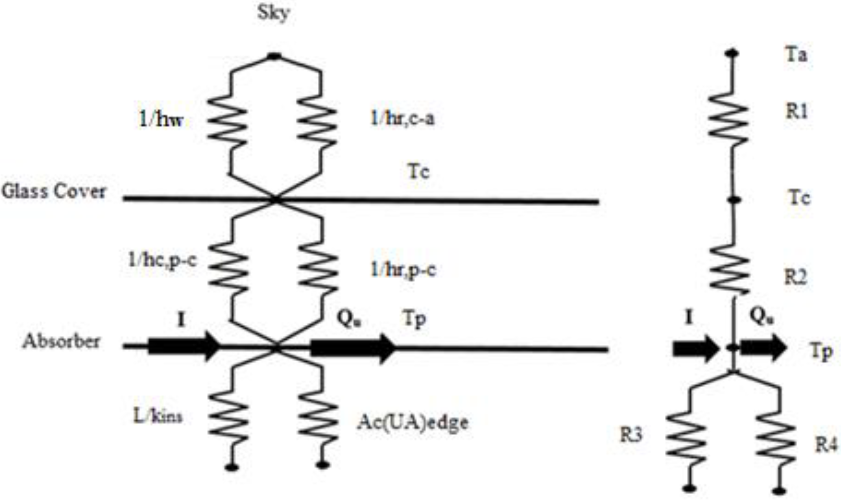
2.1. Thermal Analysis of SAH

The heat transfer in various components of the SAH is important for the analysis of the useful heat gain and thermal losses. The system thermal efficiency is evaluated by accounting for thermal losses on the side cover, back cover and top glass cover. The thermal analysis takes into consideration the following assumptions: (i) the properties of the glass cover and absorber plate materials are temperature independent, (ii) the effect of sun location (longitude and latitude) is neglected, (iii) the effect of humidity is negligible, (iv) spatial temperature variation in absorber plate is negligible, (iv) optical losses are neglected and (v) air thermo-physical properties are calculated at the average temperature. The combined convection-radiation thermal resistance between the glass cover and the sky, as well as between the absorber plate and the glass cover, are calculated using the thermal network approach, shown in Figure 4. The thermal losses of the side insulation and back cover insulation are neglected in the thermal network of the SAH.
Absorber-to-glass-cover heat transfer:
q loss , p - c = h c , c - p T p T c 1 + σ T p 4 T c 4 1 ε p + 1 ε c 1 = h c , p - c + h r , p - c T p T c
where
h r , p - c = σ T p 2 + T c 2 T p + T 1 ε p + 1 ε c 1
R 2 = 1 h c , c - p + h r , c - p
The convective heat transfer coefficient between the absorber and the glass cover is:
h c , p - c = N u k L
The Nusselt number between the glass cover and the absorber plate due to natural convection is calculated as:
N u = 1 + 1.44 1 1708 / RaCos β + 1 1708 sin 1.8 β 1.6 / Racos β + RaCos β / 5830 0.33 1
R a = g β ( T p T c ) L 3 ν α
The radiation resistance between the top cover and the sky accounts for radiative heat exchange with the sky. The radiative heat transfer coefficient is:
h r , c - a = σ ε c T c + T s T c 2 + T s 2 T c T s T c T a
The thermal resistance to the ambient is:
R 1 = 1 h r , c - a + h w
The SAH-to-ambient heat transfer coefficient is calculated as:
U t = 1 R 1 + R 2
For the edge and back sides, the heat transfer coefficients are calculated as follows:
U e = 1 R 4 = ( U A ) edge A p   and   U b = 1 R 3 = k ins L
The overall heat transfer coefficient for thermal losses is:
U o = U t + U b + U e
Heat gain to the air stream is:
Q u = I α τ U o T p T a A p
The thermal efficiency is:
η th = Q u A p I

2.2. Exergy Analysis

The exergy analysis of the SAH measures the quality of the energy exchanged in various processes such as heat gain to air flow, insolation, heat losses to the ambient air and air pumping power. Altfeld et al. [29] performed exergy analysis based on the second law of thermodynamics to establish the equivalence between friction losses and useful energy. The maximum work potential that a given form of energy can produce is measured by the exergy of the air stream. In order to optimize the SAH design, the net exergy flow of air should be maximized while exergy losses by insolation absorption, exergy losses through different surfaces and exergy losses in air pumping should be reduced to the minimum possible level. Net exergy of the air flow is expressed by following expression while assuming air as perfect gas:
E n = I A p η th η c P m ( 1 η c )
The net exergy of air is represented by the term on the left side, while the net exergy losses due to friction on the conical protrusion rib roughness are represented by the term on the right side.
The Carnot efficiency is calculated as:
η c = 1 T a T fm
The rate of exergy caused by insolation is determined by:
E s = I 1 T a T sun
Consequently, the exergy efficiency is expressed as:
η exg = E n E s

3. Mathematical Model and Validation

The exergy efficiency of the SAH is calculated using Nusselt number and friction factor correlations [28], along with the realistic ranges of solar insolation, Reynolds number and temperature increase parameters which were considered as given in the literature [23]. The geometrical parameters of conical ribs are studied in the following ranges: the rib height is between 0.020 and 0.044 while the relative rib pitch is between 6 and 12. The properties of various components of the system are listed in Table 1. The stepwise procedure for predicting the exergy efficiency is given below.
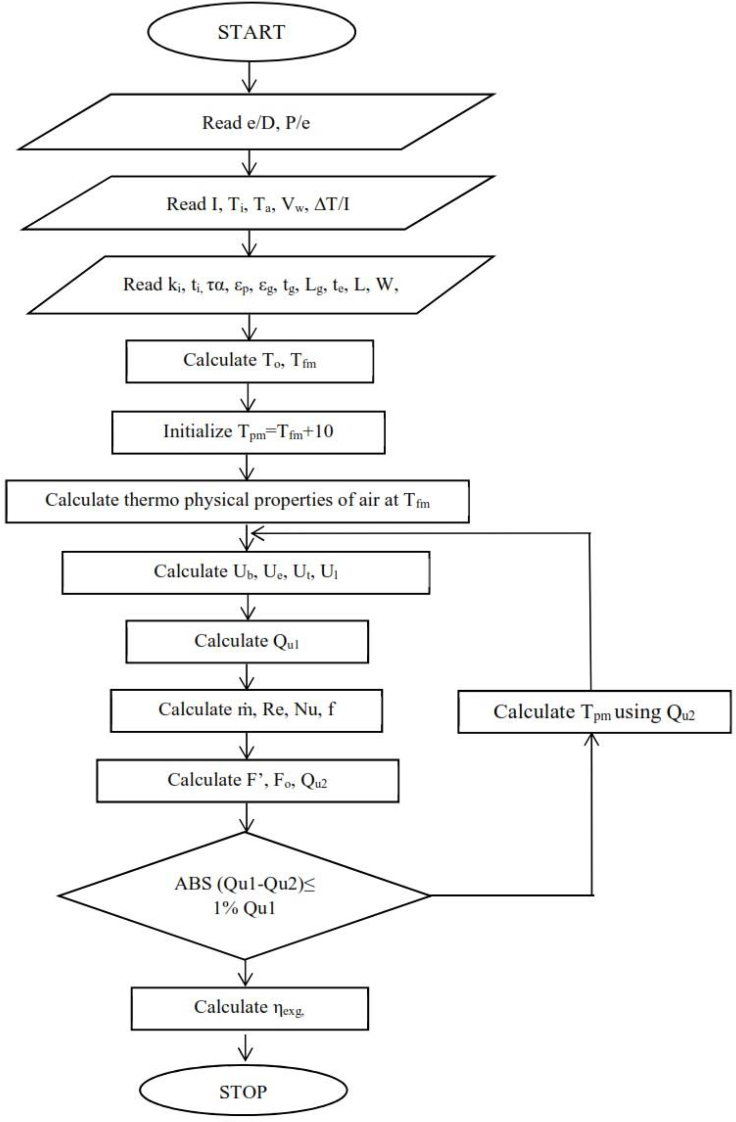
  • In the first step, rib parameters and operating parameters, such as wind speed, ambient temperature, insolation and inlet air temperature, are selected.
  • For the design temperature increase parameter, the outlet air temperature is evaluated with following equation:
    T o = Δ T I I + T i
  • The following relationships are employed to calculate the heat transfer coefficients on the back cover and side edge:
    U b = k i t i
    U e = L + W t e k i L W t i
  • The major heat losses occur at the top glass cover due to the high absorber plate temperature. The following correlation was developed by Akhtar and Mullick [31]:
    1 U t = σ T pm 2 + T g 2 T pm + T g 1 ε p + 1 ε g 1 + k a N u 1 L g 1 + σ ε g T g 2 + T a 2 T g + T a + h w 1 + t g k g
    where
    T g = F 1 T pm + c T a 1 + F 1
    F 1 = 12 10 8 T a + 0.2 T p 3 + h w 1 + 0.3 t g 6 10 8 ε p + 0.028 T pm + 0.5 T a 3 + 0.6 L g 0.2 T pm T a cos β ti 0.25 1
    T s = 0.0522 T a 1.5
    c = T s / T a + h w / 3.5 1 + h w / 3.5
    R a = G r P r
    G r = g β exp T pm T g L g 3 ν 2
  • The overall heat loss coefficient is calculated as the sum of back, side and top heat losses coefficients:
    U o = U t + U b + U e
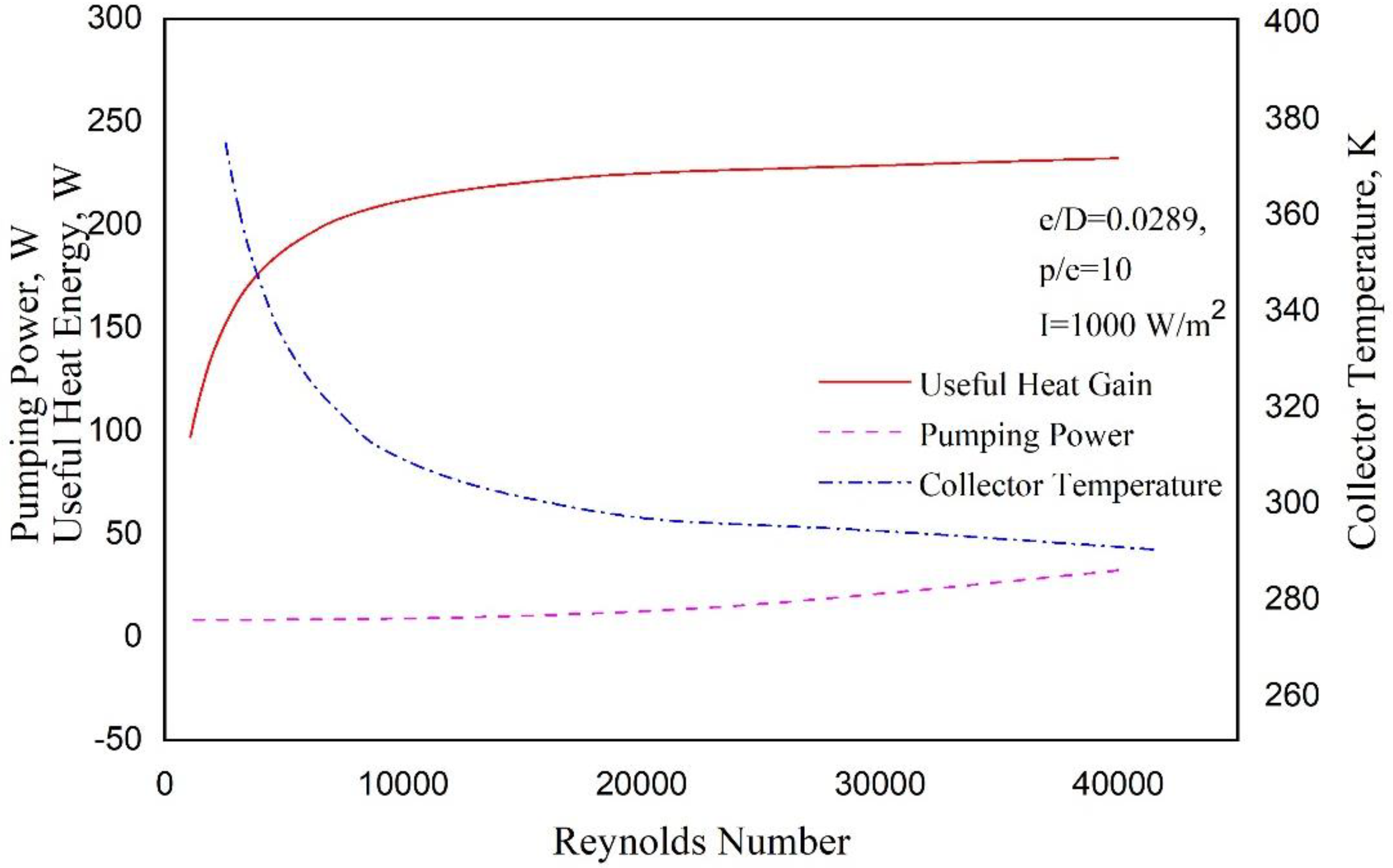
  • The following equations are used to determine the useful heat gain to the airflow, as well as the air mass flow rate and the Reynolds number:
    Q u 1 = I α τ U o T p T a A p
    m = Q u 1 C p Δ T
    R e = m D h μ ( W H )
  • The convective heat transfer coefficient of the absorber plate is determined using the following Nusselt number correlation [26]:
    h = N u k D h
    N u = 2.29 10 4 R e 0.984 e / D 0.280 ( p / e ) 4.085 e 0.922 ln ( p / e ) 2
  • The heat gain to the air stream is calculated from the collector fin efficiency and the heat removal factor:
    Q u 2 = A p F I α τ U l T o T a
    where
    F o = m C P A P U l exp F A P U l m C P 1   and   F = h h + U o
  • Qu1 and Qu2 are compared and, in case of difference between these two values, an updated value of Tpm is determined using the heat gain, Qu2, from Equation (34). The iteration continues until the values of Qu1 and Qu2 come to within 1% difference; that is, (Qu1Qu2)/Qu1 < 1%.
    T pm = T a + I α τ Q u 2 / A p U l
  • The pressure drop and the air blower power are estimated from the friction factor correlation for conical protrusion rib roughness [26]:
    f = 2.19 10 4 R e 0.352 e / D 5.839 e 0.739 ln ( e / D ) 2 ( p / e ) 1.860 e 0.523 ln ( p / e ) 2
    P m = m Δ P d ρ   and   Δ P d = 4 f L ρ V 2 2 D h
  • Finally, the exergy efficiency is calculated for the SAH with conical protrusion ribs using Equation (17), as proposed by Altfeld et al. [29]. The process is performed for different operating parameters and rib geometries. The flow chart of this approach is given in Figure 5.
The results for the predicted Nusselt numbers and friction factors are validated against experimental data for hemispherical protrusion ribs obtained at different Reynolds numbers (Re = 3054, 6119, 9701 and 11138), carried out by Verma and Saini [22]. It can be seen that the predictions are in good agreement with experiments, as presented in the authors’ previous study [28].

4. Result and Discussions

The exergy efficiency of the SAH conical protrusion ribs is assessed using the technique described in the preceding section. Regarding the Reynolds number and the temperature increase parameter, the exergy efficiency shows an indirect comparison of net exergy of air and exergy loss owing to air pumping power for different conical protrusion ribs geometries. Before discussing exergy efficiency, it is necessary to understand the behavior of usable heat gain, absorber temperature and pumping power. As a result, their respective plots are plotted relative to the Reynolds number, as shown in Figure 6. It can be seen that the absorber plate’s mean temperature decreases with Reynolds number and becomes practically constant. In contrast, the heat gain increases with Reynolds number and virtually flattens for high Reynolds numbers, which suggests that lower plate temperatures have fewer heat losses through the glass cover and high heat exchange between absorber and air flow. The pumping power increases with the Reynolds number; however, this increase is not significant.

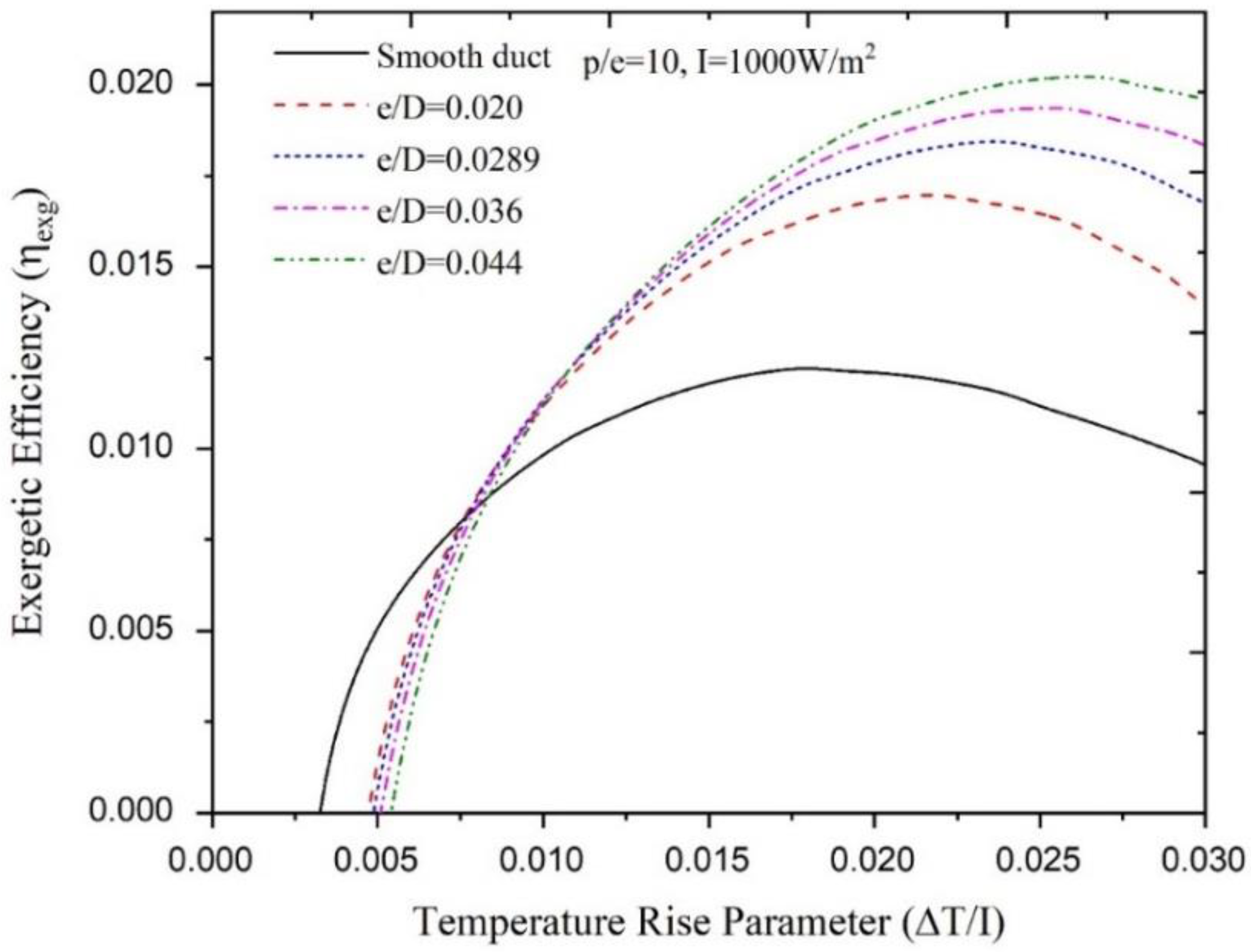
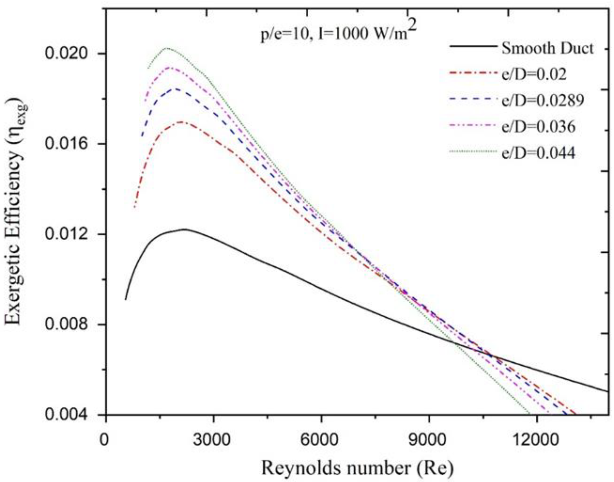
4.1. The Effect of Relative Height

The exergy efficiencies of the SAH absorber with conical protrusion ribs are studied for all combinations of relative rib height and relative rib pitch when the solar insolation is exploited from 600 W/m2 to 1000 W/m2. The exergy efficiency of conventional SAH is also assessed for comparison considerations. The exergy efficiencies for fixed rib pitch (P/e = 10) at 1000 W/m2 of solar insolation is shown in Figure 7. The exergy efficiency improves with increasing temperature rise parameter, then falls continuously for all relative rib heights, as seen in the graphs. However, differing temperature increase parameters, which are dependent on the relative rib height, produce distinct exergy efficiency peaks. Table 2 shows the range of temperature parameters at which increased exergy efficiency is seen. Smooth SAH exhibits the highest exergy efficiency for temperature increase parameters smaller than 0.0076 K∙m2/W. When the temperature increase parameter increases, the parameter for relative rib height takes precedence. The largest exergy efficiency is achieved for relative rib heights of 0.020, 0.0289 and 0.036 when the respective temperature increase parameters are 0.0076–0.0087 K∙m2/W, 0.0087–0.0101 K∙m2/W and 0.0104–0.0111 K∙m2/W. For a temperature increase parameter larger than 0.0111 K∙m2/W, the optimum exergy efficiency is achieved with a relative rib height of 0.044. At 1000 W/m2 of solar insolation, Figure 8 illustrates the fluctuation of exergy efficiency for a conical rib pitch value of P/e = 10. The exergy efficiency increases with the Reynolds number, reaches a maximum value, and subsequently decreases, as seen in the graphs. The maximum exergy efficiency has been observed for varying Reynolds numbers, which depend on the relative rib height. Similarly, Table 2 reports the optimal values of relative rib heights with respect to the ranges of the Reynolds number for which the maximum energetic efficiency is achieved. When the Reynolds number is larger than 10760, the solar air heater with smooth duct achieves the highest exergy efficiency. The solar air heater with conical protrusion ribs achieves the highest effectiveness when the Reynolds number is smaller than 10760. In the following ranges of the Reynolds number, 9700-10760, 7530-9700 and 6910-7530, the relative rib height of 0.020, 0.0289 and 0.036 exhibit the highest exergy efficiency. When the Reynolds number is less than 6910, the relative rib height of 0.044 provides optimum exergy efficiency. Table 3 reports the enhancement factor of the exergy efficiency achieved by conical protrusion ribs over varying relative rib height.

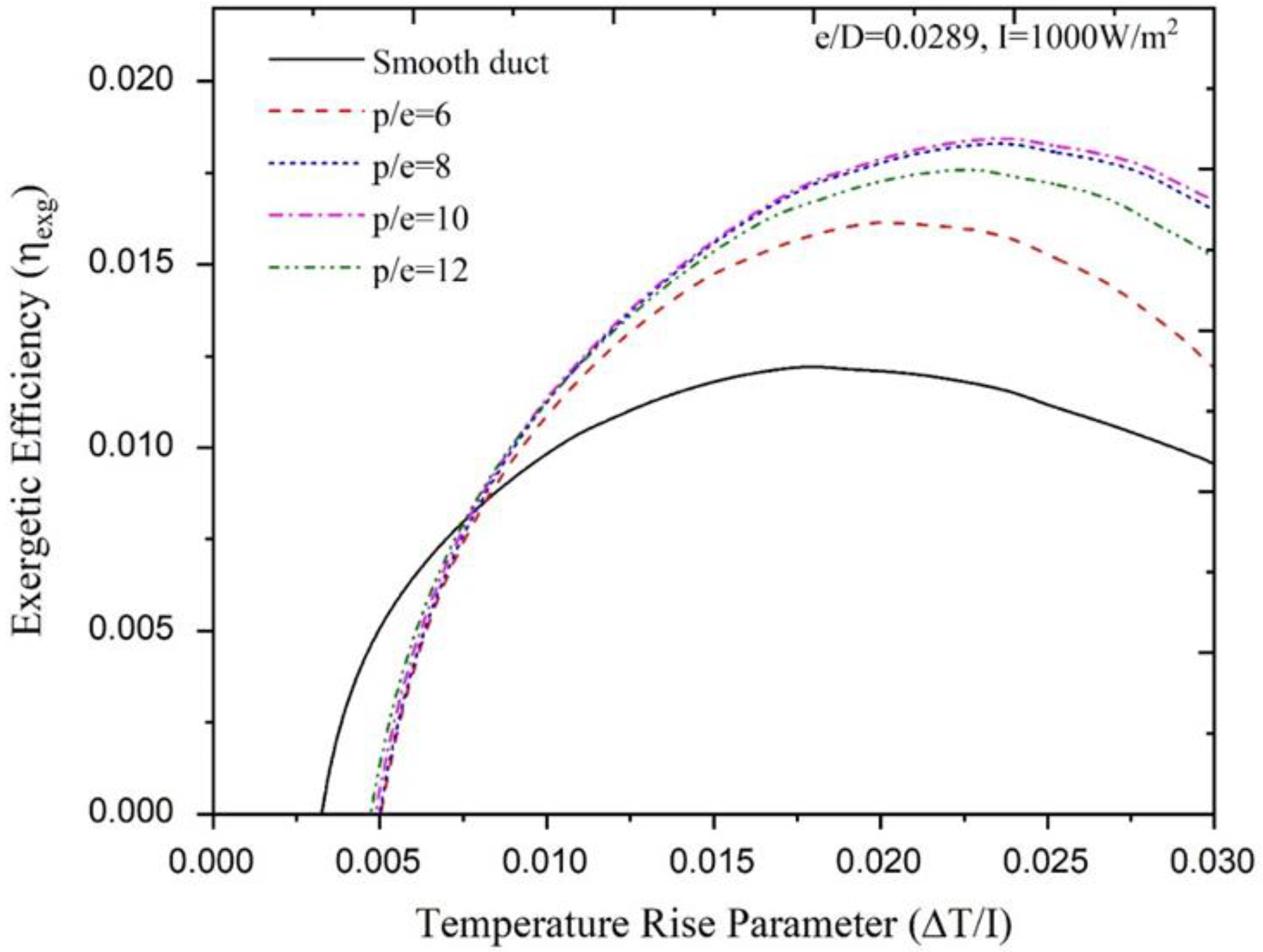
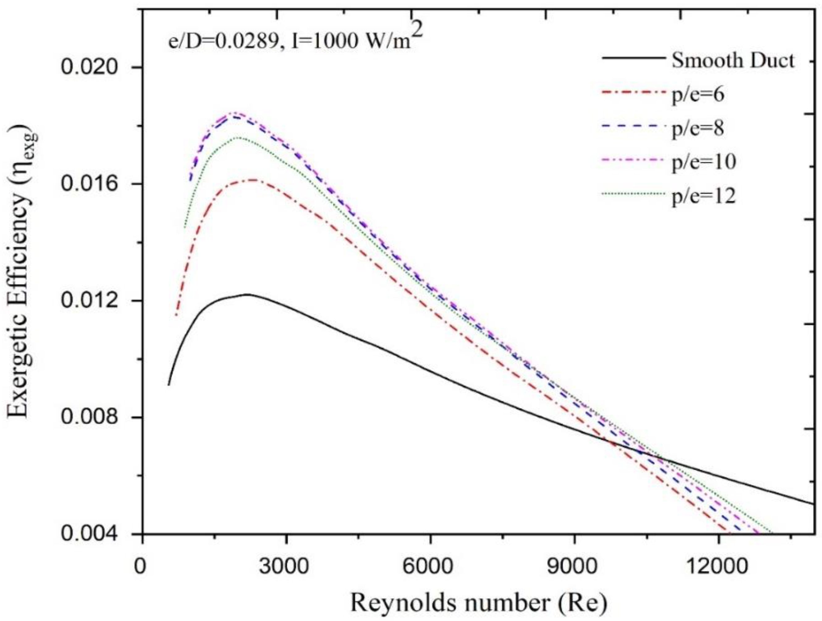
4.2. The Effect of Relative Pitch

The exergy efficiency of ribs with conical protrusions is plotted against the temperature increase parameter for different relative rib pitches but for a fixed relative rib height of e/D = 0.289 and constant solar insolation of 1000 W/m2, as shown in Figure 9. Over a range of increasing temperature increase parameter, the exergy efficiency increases at first, then achieves a maximum value and lastly decreases. The exergy efficiency maximum occurs for different temperature increase parameters, which depends on the relative rib pitch. Table 4 reports the values of relative rib pitches relative to the temperature increase parameter at which the maximum exergy efficiency is achieved. A smooth SAH achieves the highest exergy efficiency if the temperature increase parameter is smaller than 0.0076 K∙m2/W. For temperature increase parameters exceeding 0.0076 K∙m2/W, the relative rib height parameter takes precedence. A relative rib pitch value of p/e = 12 achieves the highest exegetic efficiency in the range of temperature increase parameter between 0.0076 K∙m2/W and 0.0092 K∙m2/W. When the temperature increase parameter is larger than 0.0092 K∙m2/W, the highest exergy efficiency is achieved by a relative rib pitch value of p/e = 10. At a solar insolation of 1000 W/m2, Figure 10 shows how the exergy efficiency changes with the Reynolds number if the relative rib height is constant at e/D = 0.00289. The exergy efficiency increases with the Reynolds number and, after achieving a maximum, decreases with a further increase in the Reynolds number. Table 4 reports the optimal values of rib pitches for achieving maximum exergy efficiency with respect to the Reynolds number range. When the Reynolds number is smaller than 8570, conical protrusion ribs with a relative rib pitch of p/e = 10 exhibit the optimum exergy efficiency. When the SAH works in the range of Reynolds number 8570-10870, the relative rib pitch of p/e = 12 achieves maximum exergy efficiency. When compared to the SAH with protrusion ribs, the smooth-duct SAH delivers the highest exergy efficiency for a Reynolds number larger than 10870. In addition, the plots show that relative rib pitches of p/e = 6 and 8 do not have a major impact on the SAH performance. Table 5 depicts the enhancement factor in the exergy efficiency owing to conical protrusion ribs at different values of relative rib pitches.

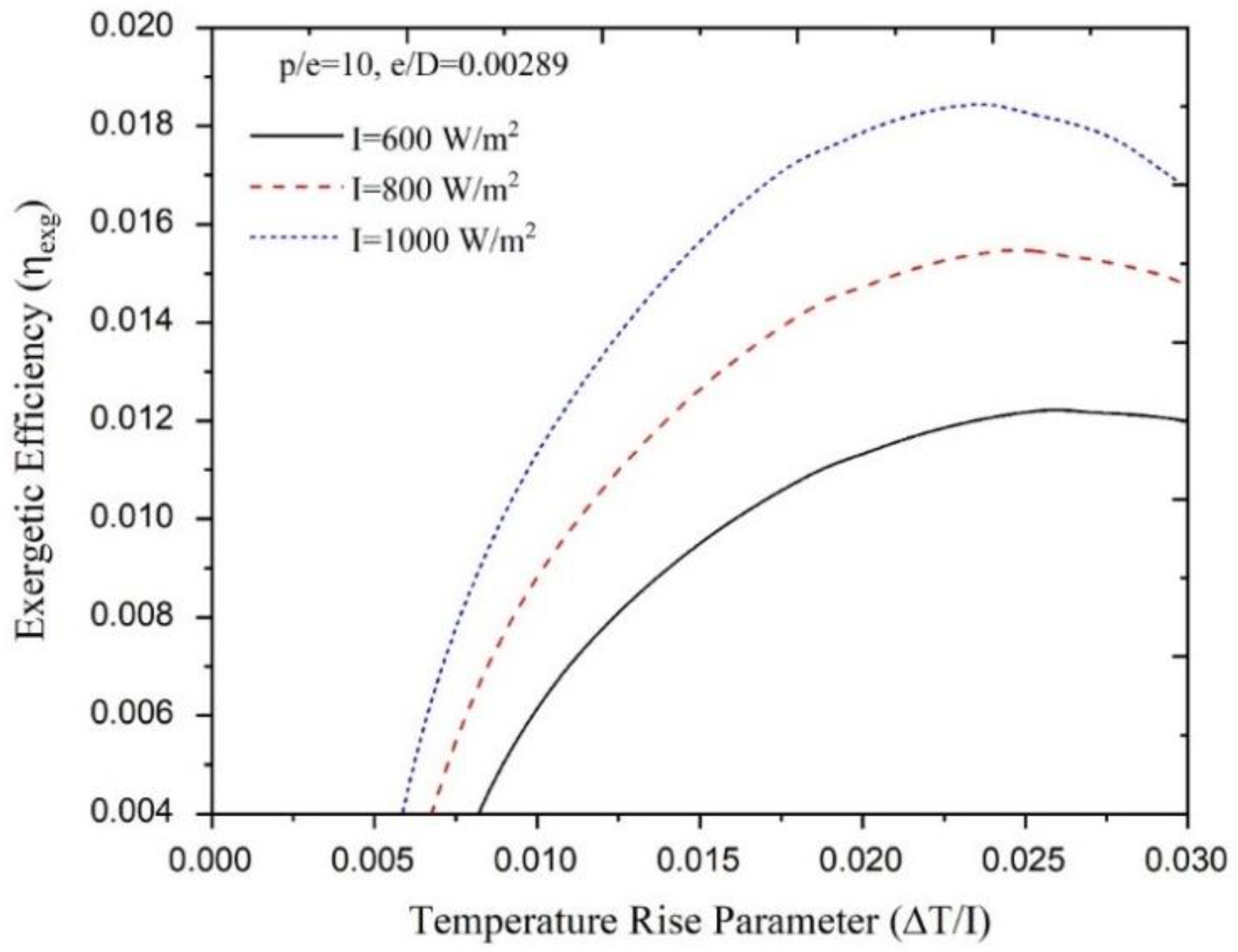
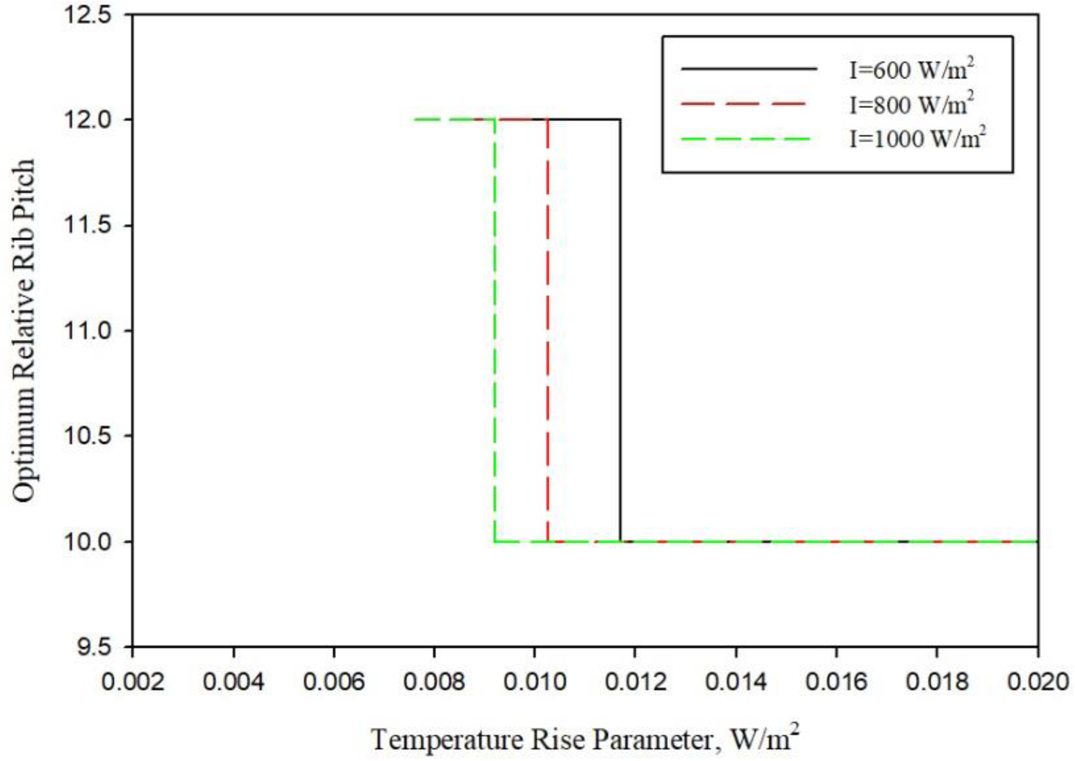
4.3. The Effect of Solar Insolation

The exergy efficiency of novel roughness in the solar air heater is studied for different values of insolation to understand the influence of solar insolation on the SAH performance. Figure 11 plots of exegetic efficiency at solar insolation from 600 W/m2 to 1000 W/m2 for constant rib parameters (p/e = 10, e/D = 0.0289). As described in the previous section, similar plots are obtained here. Over the whole range of temperature increase parameters, the maximum exergy efficiency occurs at 1000 W/m2 of solar insolation. This is because exergy associated with insolation is larger at higher insolation, which translates into higher exergy of air. Nevertheless, according to Altfeld et al. [30], exergy loss from the absorber to the environment is independent of insolation. Exergy efficiency plots are observed to peak at different values of temperature increase parameters. The exergy efficiency grows with the temperature increase parameter and, after achieving a maximum value, decreases with further increase in the temperature increase parameter. The sudden drop in exergy efficiency implies that substantial exergy is wasted due to high pumping power requirements.
The exergy efficiency of conical protrusion ribs is compared to semi-spherical dimple ribs [24], V ribs [9] and discrete V-down ribs [11], as depicted in Figure 12. The exergy efficiency of the conical protrusion ribs, semi-spherical dimple ribs, V ribs and discrete V ribs is presented with respect to the Reynolds number. Conical protrusion ribs have similar exergy efficiency trends to those of the semi-spherical dimple ribs, V ribs and discrete V ribs. At low Reynolds numbers, the exergy efficiency of the conical protrusion ribs is higher than those of other rib types. The net exergy efficiency of conical protrusion ribs is then surpassed by the exergy efficiency of the discrete V ribs. This occurs because of the larger friction factors in the conical protrusion ribs, which lead to high pumping power requirements. When compared to typical V ribs, the sharp corners of conical ribs enhance flow turbulence. The exergy efficiency of the conical protrusions decreases under the exergy efficiency of semi-spherical dimple ribs and V ribs because of the high pumping power requirements, especially at high Reynolds numbers.

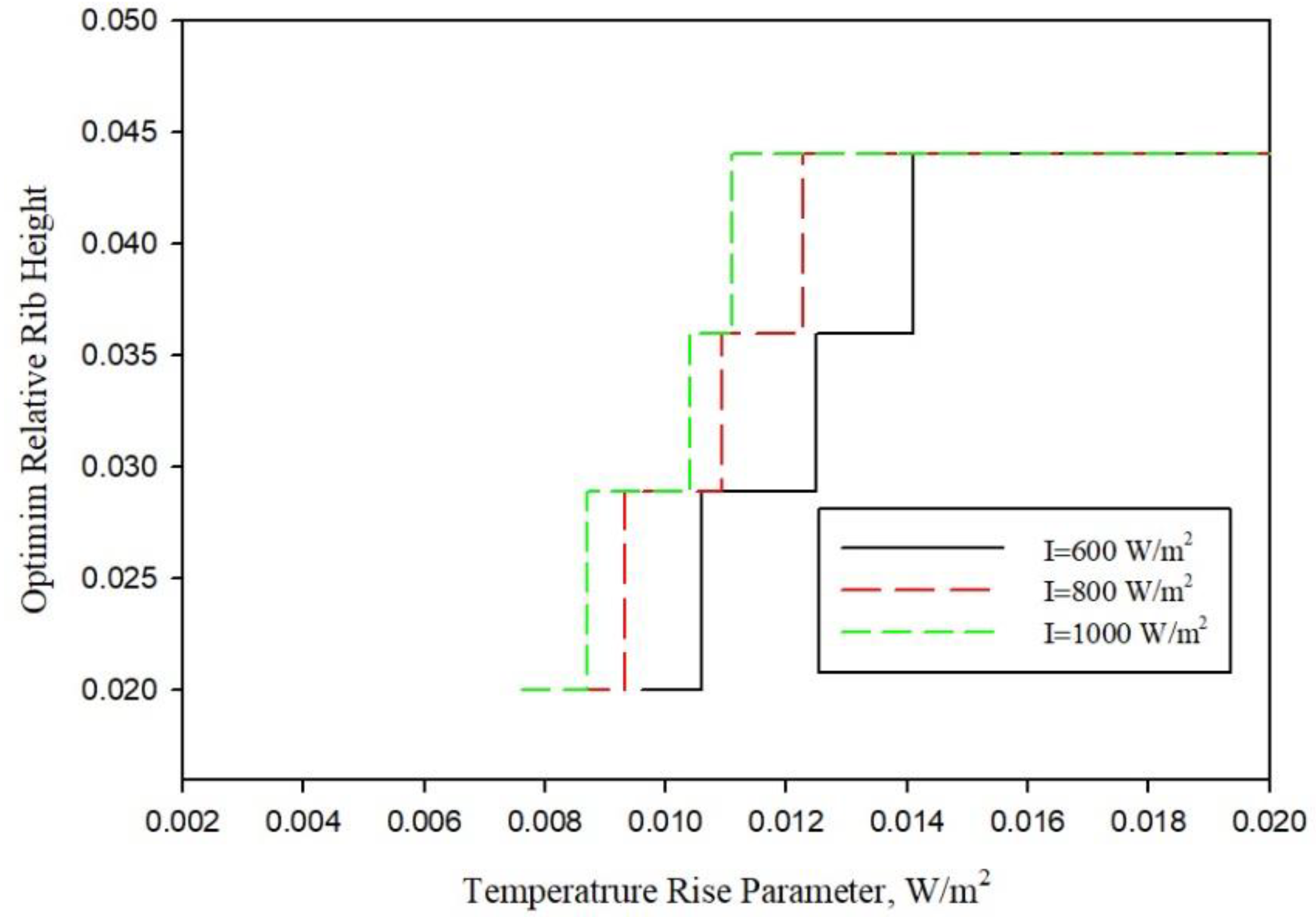
5. Optimization of the Conical Rib Parameters

The optimum rib parameters resulting in maximum exergy efficiency are estimated with respect to the temperature increase parameter. Figure 13 depicts the optimum rib height for different values of insolation (600, 800 and 1000 W/m2). When the temperature increase parameter is larger than 0.00141 W/m2∙K, the optimum relative rib height is 0.044, while a smooth duct offers maximum exergy efficiency in the case when the temperature increase is below 0.0076 W/m2∙K, at all values of solar insolation. When the temperature increase parameter is between 0.0076 W/m2∙K and 0.0141 W/m2∙K, the optimum rib height of the conical protrusion ribs depends on the value of insolation.
Similarly, for all solar insolation, the value of optimum relative rib pitch is shown in Figure 14 for all temperature increase parameters. When the temperature increase parameter is smaller than 0.0076 W/m2∙K, the SAH with a smooth duct returns higher exergy efficiency than conical protrusion ribs, for all values of rib parameters and solar insolations. However, when the temperature increase parameter is larger than 0.00117 W/m2∙K, a relative rib pitch of p/e = 10 achieves the optimum exergy efficiency.
Figure 13 and Figure 14 show the optimum rib parameters for a particular value of solar insolation and temperature increase parameter. When T/I > 0.00114 K ∙m2/W, a unique optimum combination of rib parameters is discovered, with a relative rib pitch of p/e = 10 and a relative rib height of e/D = 0.044, for all values of solar insolation.

6. Conclusions

An analytical study was performed to estimate the exergy efficiency of an SAH absorber surface with conical protrusion ribs. The exergy efficiency of the roughened absorber surface was compared to the exergy efficiency of the smooth solar air heater, operating with comparable conditions, to determine the enhancement factor. The parameters of the conical protrusion ribs were tuned for optimal exergy efficiency based on the findings. The study’s key findings are listed below:
1. The roughness of the conical protrusion ribs has a substantial impact on the exergy efficiency of the SAH duct. At e/D = 0.044 and p/e = 10, the maximum exergy efficiency was found to be 0.0202.
2. Exergy efficiency is a function of solar insolation as well. When the solar insolation is increased from 600 to 1000 W/m2, the maximum exergy efficiency increases from 0.0122 to 0.0185.
3. Exergy efficiency is a strong function of the Reynolds number; higher Reynolds numbers always result in a lower value of exergy efficiency, regardless of the rib parameters, due to high friction factors and pumping power, while, for low Reynolds numbers, the exact values of rib parameters determine the exergy efficiency.
4. There is a set of ideal conical protrusion rib parameters that match certain operating conditions, resulting in the highest exergy efficiency. The optimum rib height is determined to be 0.020, 0.0289, 0.036 and 0.044 when the temperature increase parameter is in the respective ranges of 0.0076–0.0087 K∙m2/W, 0.0087–0.0104 K∙m2/W, 0.0104–0.0111 K∙m2/W and above 0.0111 K∙m2/W. Similarly, the rib pitches of 12 and 10 are determined to be optimum solutions when the temperature increase parameter is in the respective range of 0.0076–0.0092 K∙m2/W and above 0.0092 K∙m2/W.
5. The temperature increase parameter affects the optimum rib height and rib pitch, and the range of temperature increase parameter for optimum ribs parameters changes significantly with solar insolation.
6. When the temperature increase parameter is T/I > 0.0141 K∙m2/W, a unique optimum combination of rib height of e/D = 0.044 and rib pitch of p/e = 10 is found to be independent from the value of solar insolation.
The analysis of the solar air heater thermo-hydraulic performance was used to find the optimum parameters of the conical rib protrusion ribs for the highest exergy efficiency under certain operating circumstances. The exergy efficiency characteristics will aid the designer in determining the conical protrusion rib specifications under various operating situations.

Author Contributions

Conceptualization, T.A.; methodology, T.A. and M.I.H.S.; software, H.A.; validation, T.A., M.I.H.S. and H.A.; formal analysis, P.B.; investigation, T.A., H.A. and K.S.; resources, T.A. and M.I.H.S.; data curation, H.A. and M.A.A.; writing—original draft preparation, T.A.; writing—review and editing, M.I.H.S., H.A. and K.S.; visualization, T.A. and M.A.A.; supervision, T.A.; project administration, T.A. and H.A.; funding acquisition, P.B. All authors have read and agreed to the published version of the manuscript.

Funding

This research received no external funding.

Data Availability Statement

Data available on request.

Conflicts of Interest

The authors declare no conflict of interest.

Nomenclature

Ap or AcArea of absorber plate, m2RaRayleigh Number
dDiameter of conical rib, mmReReynolds number
DDuct height, mmTaAmbient Temperature, °K
DhHydraulic diameter, mteEdge thickness, mm
eRib height, mmTfmFluid mean temperature, °K
e/DRelative rib heighttgGlass Thickness, mm
EnExergy flow rate to air, WTiInlet air stream temp, K
EnExergy of the air flow, WToOutlet air stream temp, K
EsExergy of solar radiation, WTpm or TcPlate mean temp, K
EsExergy of solar radiation, WTsunSun temperature, K
fFriction factor in roughened ductUHeat transfer coeff., W/m2∙K
FFin efficiency factor,U0Overall heat transfer coeff., W/m2⋅K
FoHeat removal factor UbHeat transfer coeff. of back cover, W/m2⋅K
fsFriction factor in smooth ductUeHeat transfer coeff. of side edge, W/m2⋅K
GrGrashof NumberUtHeat transfer coeff of top cover, W/m2⋅K
hConvective heat transfer coefficient, W/m2∙KVAir velocity, m/s
hc,p-cConvective heat transfer coeff. between absorber and glass cover, W/(m2 K)WDuct width, mm
hr,c-aRadiative heat transfer coeff. between glass cover and ambient, W/(m2 K)ΔPdPressure drop, Pa
hr,p-cRadiative heat transfer coeff. between absorber and glass cover, W/(m2 K)ΔT/ITemperature increase parameter, K∙m2/W
hwConvective heat transfer coeff. of wind, W/(m2 K)Greek Symbols
IInsolation, W/m2αThermal diffusivity, m2/s
kaAir thermal conduc., W/(m⋅K)βTilt angle, º
KgGlass thermal conduc., W/(m⋅K)β′Coeff. of expansion, 1/°K
kinsInsulation thermal conduc., W/(m⋅K)εgGlass cover emissivity
LCollector length, mεpAbsorber plate emissivity
LgGlass cover length, mηthThermal efficiency
mMass flow rate, kg/sηexgExergy efficiency
NNumber of glass coverηcCarnot efficiency
PmPumping power, WρAir density, kg/m3
PrPrandlt numberτTransmissivity of glass
QuUseful heat gain, J
R1Thermal resistance between class cover and ambient, K/W
R2Thermal resistance between absorber plate and glass cover, K/WµDynamic viscosity of air, N∙s/m2
R3Thermal resistance due to side edge, K/W(τ∙α)Transmittance-absorptance product of glass
R4Thermal resistance due to back cover, K/WυKinematic viscosity, m2/s

References

  1. Duffie, J.A.; Beckman, W.A. Solar Engineering Thermal Processes; John Wiley: New York, NY, USA, 1991. [Google Scholar]
  2. Alam, T.; Saini, R.P.; Saini, J.S. Heat and flow characteristics of air heater ducts provided with turbulators—A review. Renew. Sustain. Energy Rev. 2014, 31, 289–304. [Google Scholar] [CrossRef]
  3. Alam, T.; Saini, R.P.; Saini, J.S. Use of turbulators for heat transfer augmentation in an air duct–A review. Renew. Energy 2014, 62, 689–715. [Google Scholar] [CrossRef]
  4. Alam, T.; Balam, N.B.; Kulkarni, K.S.; Siddiqui, M.I.H.; Kapoor, N.R.; Meena, C.S.; Kumar, A.; Cozzolino, R. Performance Augmentation of the Flat Plate Solar Thermal Collector: A Review. Energies 2021, 14, 6203. [Google Scholar] [CrossRef]
  5. Alam, T.; Kim, M.H. A critical review on artificial roughness provided in rectangular solar air heater duct. Renew. Sustain. Energy Rev. 2017, 69, 387–400. [Google Scholar] [CrossRef]
  6. Prasad, B.N.; Saini, J.S. Optimal thermohydraulic performance of artficially roughened solar air heaters. Sol. Energy 1991, 47, 91–96. [Google Scholar] [CrossRef]
  7. Prasad, B.N.; Saini, J.S. Effect of artificial roughness on heat transfer and friction factor in a solar air heater. Sol. Energy 1988, 41, 555–560. [Google Scholar] [CrossRef]
  8. Gupta, D.; Solanki, S.C.; Saini, J.S. Heat and fluid flow in rectangular solar air heater ducts having transverse rib roughness on absorber plates. Sol. Energy 1993, 51, 31–37. [Google Scholar] [CrossRef]
  9. Ebrahim-Momin, A.M.; Saini, J.S.; Solanki, S.C. Heat transfer and friction in solar air heater duct with V-shaped rib roughness on absorber plate. Int. J. Heat Mass Transf. 2002, 45, 3383–3396. [Google Scholar] [CrossRef]
  10. Hans, V.S.; Saini, R.P.; Saini, J.S. Heat transfer and friction factor correlations for a solar air heater duct roughened artificially with multiple v-ribs. Sol. Energy 2010, 84, 898–911. [Google Scholar] [CrossRef]
  11. Singh, S.; Chander, S.; Saini, J.S. Exergy based analysis of solar air heater having discrete V-down rib roughness on absorber plate. Energy 2012, 37, 749–758. [Google Scholar] [CrossRef]
  12. Kumar, A.; Saini, R.P.; Saini, J.S. Experimental investigation on heat transfer and fluid flow characteristics of air flow in a rectangular duct with Multi v-shaped rib with gap roughness on the heated plate. Sol. Energy 2012, 86, 1733–1749. [Google Scholar] [CrossRef]
  13. Gawande, V.B.; Dhoble, A.S.; Zodpe, D.B.; Chamoli, S. Experimental and CFD investigation of convection heat transfer in solar air heater with reverse L-shaped ribs. Sol. Energy 2016, 131, 275–295. [Google Scholar] [CrossRef]
  14. Kumar, R.; Goel, V.; Singh, P.; Saxena, A.; Kashyap, A.S.; Rai, A. Performance evaluation and optimization of solar assisted air heater with discrete multiple arc shaped ribs. J. Energy Storage 2019, 26, 100978. [Google Scholar] [CrossRef]
  15. Wang, D.; Liu, J.; Liu, Y.; Wang, Y.; Li, B.; Liu, J. Evaluation of the performance of an improved solar air heater with “S” shaped ribs with gap. Sol. Energy 2020, 195, 89–101. [Google Scholar] [CrossRef]
  16. Layek, A.; Saini, J.S.; Solanki, S.C. Effect of chamfering on heat transfer and friction characteristics of solar air heater having absorber plate roughened with compound turbulators. Renew. Energy 2009, 34, 1292–1298. [Google Scholar] [CrossRef]
  17. Layek, A.; Saini, J.S.; Solanki, S.C. Heat transfer and friction characteristics for artificially roughened ducts. Int. J. Heat Mass Transf. 2007, 50, 4845–4854. [Google Scholar] [CrossRef]
  18. Juarker, A.R.; Saini, J.S.; Ghandi, B.K. Heat transfer and friction characteristics of rectangular solar air heater duct using rib-grooved artificial roughness. Sol. Energy 2006, 80, 895–907. [Google Scholar] [CrossRef]
  19. Juarker, A.R. Heat and fluid flow characteristics of rib-groove artificially roughened solar air heater. Indian Inst. Technol. Roorkee 2005. [Google Scholar]
  20. Alam, T.; Saini, R.P.; Saini, J.S. Effect of circularity of perforation holes in V-shaped blockages on heat transfer and friction characteristics of rectangular solar air heater duct. Energy Convers. Manag. 2014, 86, 952–963. [Google Scholar] [CrossRef]
  21. Alam, T.; Saini, R.P.; Saini, J.S. Heat Transfer Enhancement due to V-Shaped Perforated Blocks in a Solar Air Heater Duct. Appl. Mech. Mater. 2014, 619, 125–129. [Google Scholar] [CrossRef]
  22. Saini, R.P.; Verma, J. Heat transfer and friction factor correlations for a duct having dimple-shape artificial roughness for solar air heaters. Energy 2008, 33, 1277–1287. [Google Scholar] [CrossRef]
  23. Sethi, M.; Varun Thakur, N.S. Correlations for solar air heater duct with dimpled shape roughness elements on absorber plate. Sol. Energy 2012, 86, 2852–2861. [Google Scholar] [CrossRef]
  24. Sethi, M.; Thakur, N.S.; Varun. Heat transfer and friction characteristics of dimple-shaped roughness element arranged in angular fashion (arc) on the absorber plate of solar air heater. J. Renew. Sustain. Energy 2012, 4, 023112. [Google Scholar] [CrossRef]
  25. Bhushan, B.; Singh, R. Nusselt number and friction factor correlations for solar air heater duct having artificially roughened absorber plate. Sol. Energy 2011, 85, 1109–1118. [Google Scholar] [CrossRef]
  26. Perwez, A.; Kumar, R. Thermal performance investigation of the flat and spherical dimple absorber plate solar air heaters. Sol. Energy 2019, 193, 309–323. [Google Scholar] [CrossRef]
  27. Yadav, S.; Kaushal, M.; Varun, S. Nusselt number and friction factor correlations for solar air heater duct having protrusions as roughness elements on absorber plate. Exp. Therm. Fluid Sci. 2013, 44, 34–41. [Google Scholar] [CrossRef]
  28. Alam, T.; Kim, M.H. Heat transfer enhancement in solar air heater duct with conical protrusion roughness ribs. Appl. Therm. Eng. 2017, 126, 458–469. [Google Scholar] [CrossRef]
  29. Sharma, S.K.; Kalamkar, V.R. Thermo-hydraulic performance analysis of solar air heaters having artificial roughness–A review. Renew. Sustain. Energy Rev. 2015, 41, 413–435. [Google Scholar] [CrossRef]
  30. Altfeld, K.; Leiner, W.; Fiebig, M. Second law optimization of plat-plate solar air heaters. Sol. Energy 1988, 41, 127–132. [Google Scholar] [CrossRef]
  31. Akhtar, N.; Mullick, S.C. Approximate method for computation of glass cover temperature and top heat-loss coefficient of solar collectors with single glazing. Sol. Energy 1999, 66, 349–354. [Google Scholar] [CrossRef]
Figure 1. Schematic diagram of SAH. (a) Cross Sectional view of SAH. (b) 3D view of SAH [20,21].
Applsci 12 01696 g001
Figure 2. Conical protrusion rib.
Applsci 12 01696 g002
Figure 3. Flow around protrusion rib.
Applsci 12 01696 g003
Figure 4. Thermal resistance of SAH.
Applsci 12 01696 g004
Figure 5. Flow chart of the analytical method.
Applsci 12 01696 g005
Figure 6. Absorber temperature variation, air heat gains and pumping power.
Applsci 12 01696 g006
Figure 7. Exergy efficiency as function of ΔT/I.
Applsci 12 01696 g007
Figure 8. Exergy efficiency as function of Re.
Applsci 12 01696 g008
Figure 9. Exergy efficiency as function of ΔT/I.
Applsci 12 01696 g009
Figure 10. Exergy efficiency as function of Re.
Applsci 12 01696 g010
Figure 11. Exergy efficiency as function of insolation.
Applsci 12 01696 g011
Figure 12. Comparison between the exergy efficiencies of different rib types.
Applsci 12 01696 g012
Figure 13. Optimized rib height.
Applsci 12 01696 g013
Figure 14. Optimized rib pitch.
Applsci 12 01696 g014
Table 1. Parameters.
System ParameterValue
Emissivity of absorber plate (εp)0.9
Transmittance-absorptance product (ατ)0.8
Emissivity of transparent glass cover (εg)0.88
Tilt angle (β)30°
Collector edge thickness (te)0.1 m
Glass cover thickness (tg)0.002 m
Thickness of back insulation (ti)0.05 m
Insulation thermal conductivity (kin)0.037 W/m∙K
Collector length (L)1.0 m
Distance between glass cover and collector (Lg)0.025 m
Collector width (W)0.3 m
Number of glass covers (N)1
Collector duct height (H)0.025 m
Relative rib pitch (p/e)6–12
Relative rib height (e/D)0.020–0.044
Operating Parameters
Reynolds number1000–15000
Insolation (I)600–1000 W/m2
Temperature increase parameter (ΔT/I)0.010–0.030 K∙m2/W
Table 2. Optimum values of rib height.
p/e = 10 and I = 1000 W/m2
ParameterOptimum ValueΔT/IRe
e/DSmoothT/I < 0.0076Re > 10760
e/D = 0.02000.0076 < ∆T/I < 0.00879700 < Re < 10760
e/D = 0.02890.0087 < ∆T/I < 0.01047530 < Re < 9700
e/D = 0.03600.0104 < ∆T/I < 0.01116910 < Re < 7530
e/D = 0.04400.0111 < ∆T/IRe < 6910
Table 3. Enhancement factors for exergy efficiency.
P/e = 10, I = 1000 W/m2ΔT/I = 0.005ΔT/I = 0.01ΔT/I = 0.015ΔT/I = 0.020ΔT/I = 0.025
Enhancement factor (ηexgexgs)e/D = 0.02001.141.281.391.481.45
e/D = 0.02891.161.331.481.641.75
e/D = 0.03601.151.351.531.741.92
e/D = 0.04401.141.371.581.812.04
Table 4. The optimum rib pitch.
I = 1000 W/m2 and e/D = 0.0289
ParameterOptimum ValueΔT/IRe
p/eSmoothT/I < 0.0076Re > 10870
p/e = 120.0076 < ∆T/I < 0.00928570 < Re < 10870
p/e = 100.0092 < ∆T/IRe < 8570
Table 5. The enhancement factor in exergy efficiency for varying rib pitches.
e/D = 0.0289, I = 1000 W/m2ΔT/I = 0.010ΔT/I = 0.015ΔT/I = 0.020ΔT/I = 0.025ΔT/I = 0.030
Enhancement factor (ηexg/ηexgs)p/e = 61.111.251.341.371.27
p/e = 81.151.321.471.621.72
p/e = 101.161.331.481.641.75
p/e = 121.151.31.431.551.59
Publisher’s Note: MDPI stays neutral with regard to jurisdictional claims in published maps and institutional affiliations.

