Article

A Model for Energy Consumption of Main Cutting Force of High Energy Efficiency Milling Cutter under Vibration

Key Laboratory of Advanced Manufacturing and Intelligent Technology, Ministry of Education, Harbin University of Science and Technology, Harbin 150080, China
*
Author to whom correspondence should be addressed.
Appl. Sci. 2022, 12(3), 1531; https://doi.org/10.3390/app12031531
Submission received: 10 December 2021 / Revised: 21 January 2022 / Accepted: 27 January 2022 / Published: 31 January 2022

Abstract

:
Understanding the influence of the main cutting force energy consumption of the milling cutter is the basis for prediction and control of energy and machining efficiency. The existing models of cutting force energy consumption lack variables related to milling vibration and cutter teeth errors. According to the instantaneous bias of the main profile of the milling cutter under vibration, the instantaneous cutting boundary of the cutter teeth was investigated. The energy consumption distribution of the instantaneous main cutting force of the cutter tooth was studied. The model for the energy consumption of the instantaneous main cutting force of the cutter tooth and the milling cutter were both developed. The formation of energy consumption of the dynamic main cutting force of a high energy efficiency milling cutter was researched. A method for identifying the time–frequency characteristics of the energy consumption of the main cutting force under vibration was proposed and verified by experiments.

1. Introduction

High energy efficiency milling cutters are widely used in the manufacturing of heavy machine tools and aircraft components. The energy consumption of the main cutting force of the cutter is an important indicator for revealing the cutting process of the milling cutter and evaluating the cutting energy efficiency of the milling cutter [1]. During the intermittent cutting process, the main cutting force of the milling cutter random changes under the effects of the vibration and impact between cutter and workpiece. The energy consumption of the main cutting force of the milling cutter thus changes dynamically, which would lead to difficulty in precisely predicting and controlling energy consumption in the cutting process [2].
The instantaneous multi-tooth cutting method of the high energy efficiency milling cutter determined that the main cutting force energy consumption of the milling cutter was composed of the instantaneous main cutting force energy consumption of each tooth participating in the cutting. The instantaneous energy consumption distribution of the main cutting force on the cutting edge of the cutter tooth was the key to revealing the dynamic characteristics of the energy consumption of the main cutting force of the high energy efficiency milling cutter [3]. The non-straight tooth structures, such as helical teeth commonly used in high-efficiency milling cutters, varies the instantaneous cutting speed vector direction of each point on the cutting edge [4]. At the same time, affected by milling vibration and tooth error, the main section of the milling cutter and the instantaneous cutting behavior of the cutter teeth are in an unstable state in the workpiece coordinate system space [5]. As a result, the instantaneous cutting contact relationship between the tool tooth and the workpiece is constantly changing, which causes the magnitude and direction of the instantaneous main cutting force at each point on the cutting edge of the cutter tooth to change continuously, rendering the instantaneous main cutting force relationship between the cutter teeth uncertain [6].
The energy consumption of the main cutting force of the milling cutter by multiplying the result of the composition cutting force of the tooth of the milling cutter or the main cutting force of the milling cutter obtained through experiments with the cutting speed of the milling cutter was calculated [7]. Based on the response of the maximum or average value of the energy consumption of the main cutting force to the cutting parameters, the factors affecting the energy consumption of the main cutting force of the milling cutter were identified [8]. The above method assumed that the instantaneous cutting behavior of each tooth of the milling cutter had the same change characteristics. It was impossible to reveal the instantaneous bias of the main section of the milling cutter and the changes of the instantaneous cutting speed vector and the instantaneous main cutting force vector at each point on the cutting edge, as well as its influence on the energy consumption of the cutter tooth and the instantaneous main cutting force of the milling cutter. Thus, it is necessary to conduct in-depth research.
Establishing the correct cutter–workpiece engagement and cutting force model is the prerequisite for revealing the dynamic characteristics of the main cutting force energy consumption [9]. In recent years, Utsumi [10] used the contact behavior of the cutter and a workpiece to predict the simulation model of the milling force, which was consistent with the experimental results of several combinations of the predicted cutting forces and the cutter postures and feed rates; Jun [11,12] studied the changing law of cutting forces and established an empirical model of cutting forces on cutting parameters; Cai [13] proposed a new cutting force prediction model based on non-uniform rational basis splines and finite element methods, and established a single-insert cutting force model using NURBS interpolation. Wan [14,15] established a material separation model by combining plastic formation theory with slip line field theory, and based on the developed separation model, established a cutting force model that can consider shear and plowing effects separately; Zhang [16,17,18] developed a new universal instantaneous force model and analyzed and established the average uncut chip thickness, actual cutting depth, center position, and geometric relationship. Based on the above, He [19] established a model of the three goals energy consumption, cutting force, and processing time and processing parameters, and then obtained the Pareto optimal; Wang [20] established energy consumption models for faces, steps, grooves, and flutes on the basis of the study of energy consumption based on plastic deformation. The above methods had guiding significance for the establishment of the solution model of the energy consumption dynamic characteristics of the milling cutter’s main cutting force. However, because it ignored the influence of the non-straight tooth structure of the milling cutter, milling vibration, and tooth error—as well as the difference in the instantaneous cutting behavior of each tooth—there was a principal error in the calculation of cutting force energy consumption. This cannot correctly reflect the dynamic characteristics of the main cutting force energy consumption of the milling cutter.
In this paper, the model of the instantaneous cutting behavior in terms of contact angle and tool deviation under vibration were studied. The instantaneous bias of the main section of the milling cutter was quantitatively described. The instantaneous cutting boundary and cutting layer parameters of the milling micro-element were investigated based on the instantaneous cutting behavior model. The main cutting force energy consumption and its distribution on the rear face of the milling cutter were both investigated based on the calculation of cutting speed and main cutting force vector. The dynamic evolution of the energy consumption of the main cutting force of milling cutter was researched and also validated by experiments.

2. Instantaneous Bias of the Main Section of the Milling Cutter under Vibration

In order to reveal the dynamic characteristics of instantaneous main cutting force energy consumption of milling cutter under milling vibration, the bias of the main section of the milling cutter caused by milling vibration was analyzed, as shown in Figure 1. The variables in Figure 1 are explained as shown in Table 1.
In order to obtain the instantaneous main cutting force and main motion speed of the cutter tooth, a transformation matrix between the cutter tooth coordinate system and the workpiece coordinate system was proposed, as shown in Equations (1)–(3). The transformation matrix was solved by using the relationship between the reference coordinate system of dynamic cutting of the high energy efficiency milling cutter under vibration in Figure 1.
Q 1 = cos θ i sin θ i 0 0 sin θ i cos θ i 0 0 0 0 1 0 0 0 0 1 , Q 2 = cos φ d ( t ) sin φ d ( t ) 0 0 sin φ d ( t ) cos φ d ( t ) 0 0 0 0 1 0 0 0 0 1
Q 3 = cos θ s 1 ( t ) sin θ s 1 ( t ) 0 0 sin θ s 1 ( t ) cos θ s 1 ( t ) 0 0 0 0 1 0 0 0 0 1 ,   Q 4 = cos θ s 2 ( t ) 0 sin θ s 2 ( t ) 0 0 1 0 0 sin θ s 2 ( t ) 0 cos θ s 2 ( t ) 0 0 0 0 1
M 1 = 1 0 0 0 0 1 0 0 0 0 1 Δ z d i 0 0 0 1 , M 2 = 1 0 0 A x ( t ) 0 1 0 A y ( t ) 0 0 1 A z ( t ) 0 0 0 1 , M 3 = 1 0 0 x o o ( t ) 0 1 0 y o o ( t ) 0 0 1 z o o ( t ) 0 0 0 1
where Q1, Q2, Q3, and Q4 are rotation matrices and M1, M2, and M3 are translation matrices. φd(t) is the instantaneous angle between yd axis and ys axis in xsosys plane, which could be expressed as
φ d ( t ) = φ d ( 0 ) + 2 π n · t φ d ( 0 ) + 2 π n · t 2 π · 2 π
where φd(0) is the initial cutting time of the milling cutter, that is, the angle between yd axis and ys axis in xsosys plane when t is 0.
xoo(t), yoo(t), zoo(t) are the instantaneous position coordinate of the coordinate origin oo of the milling cutter cutting coordinate system without vibration in the workpiece coordinate system o-xyz, which could be solved as
x o o ( t ) = v f · t x ( 0 ) y o o ( t ) = y L a e + r max z o o ( t ) = z H a p
The instantaneous bias state of the main section of the milling cutter was characterized by the bias angle of the cutting coordinate system caused by milling vibration.
The milling cutter trajectory os(x,y,z) in cutting coordinate system under vibration could be written as
o s ( x , y , z ) = x y z 1 T = M 3 · A x ( t ) A y ( t ) A z ( t ) 1 T
The speed v(t) of the milling cutter in the direction of the cutting vector along the os(x, y, z) motion trajectory could be expressed as
v ( t ) = d o s ( x , y , z ) d t
The instantaneous angle between xs axis and xo axis θs(t) could be derived as
θ s ( t ) = arccos x s · x o x s · x o = arccos v x ( t ) v x 2 ( t ) + v y 2 ( t ) + v z 2 ( t )
where vx(t), vy(t), and vz(t) are the components of v(t) along the x axis, y axis, and z axis, respectively.
The angle between the projection of xs axis on xoooyo plane and xooozo plane and xo axis could be calculated as
θ s 1 ( t ) = arcsin v y ( t ) v x 2 ( t ) + v y 2 ( t ) ,   θ s 2 ( t ) = arcsin v z ( t ) v x 2 ( t ) + v z 2 ( t )
The bias angle of main section of the milling cutter θ(t) could be written as
θ ( t ) = arctan v z ( t ) v x 2 ( t ) + v y 2 ( t )
In order to investigate the effect of milling vibration on cutting posture of the milling cutter, the bias angle and the trajectory of milling cutter with/without vibration were compared by using Equations (1)–(10), as shown in Figure 2.
As shown in Figure 2, the trajectory and bias angle of milling cutter remained constant without milling vibration, the milling vibration could cause displacement increment of the milling cutter in different degrees, which directly changed the trajectory and bias angle of the milling cutter, resulting in the continuous changes in instantaneous cutting boundary of the cutter tooth, which directly affected the formation process of the main cutting force energy consumption of the milling cutter.

3. Solution Method of the Cutter Tooth Instantaneous Cutting Boundary under Vibration

In order to solve the interval of the distribution function of the energy consumption of the cutter tooth’s main cutting force under the action of vibration, the instantaneous cutting boundary of the cutter tooth should be investigated. By using Equations (1)–(10), in the workpiece coordinate system, the cutting edge Ei(x, y, z) of ith cutter tooth could be written as
E i ( x , y , z ) = x ( t ) y ( t ) z ( t ) 1 = Ω i · r i · sin ζ i r i · cos ζ i ( ζ i / 360 ) · 2 π r i · cot β 1 r i = r max Δ r i ,     ζ i 0 °
The transformation matrix Ωi between the cutter tooth coordinate system and the workpiece coordinate system could be expressed as
Ω i = M 3 · M 2 · Q 4 · Q 3 · Q 2 · M 1 · Q 1
when ζi = 0° in Equation (11), the trajectory si(x, y, z) of the cutter tip in the workpiece coordinate system could be expressed as
s i ( x , y , z ) = x y z 1 T = Ω i · 0 r i 0 1 T
During the milling process, the instantaneous cutting edge and the machining transition surface of the workpiece are shown in Figure 3.
According to Figure 3, when the ith cutter tooth cut into the side elevation GL of the workpiece to be machined, the curve equation of the upper boundary characteristic point of the cutting edge could be expressed as
m i k L ( t i ) = E i ( x , y , z ) = x ( t i ) y ( t i ) z ( t i ) 1 T y ( t i ) = y L , t 1 i t i t 2 i
where ti is the characteristic moment when the cutting edge of the ith cutter tooth cut the workpiece, and ti1 is the cutter tip of the ith cutter tooth, that is, the characteristic moment when the point at which the cutting edge lag angle ζi is equal to 0° cuts into the side elevation GL of the workpiece to be processed, ti2 is the characteristic moment when the cutting edge of the ith cutter tooth cuts away from the side elevation GL and cuts into the upper surface GH of the workpiece.
Then the characteristic moment ti1 could be expressed as
m i k L ( t 1 i ) = E i ( x , y , z ) = x ( t 1 i ) y ( t 1 i ) z ( t 1 i ) 1 T y ( t 1 i ) = y L , ζ i = 0 °
The characteristic moment ti2 could be expressed as
m i k L ( t 2 i ) = E i ( x , y , z ) = x ( t 2 i ) y ( t 2 i ) z ( t 2 i ) 1 T y ( t 1 i ) = y L , z ( t 2 i ) = z H
when the ith cutter tooth cut into the upper surface GH of the workpiece, the curve equation of the characteristic point on the upper boundary of the cutting edge could be expressed as
m i k H ( t i ) = E i ( x , y , z ) = x ( t i ) y ( t i ) z ( t i ) 1 T z ( t i ) = z H , t 2 i t i t 4 i
where ti4 is the characteristic moment at which the cutting edge of the ith cutter tooth on the upper surface GH of the workpiece cuts out of the machining transition surface Σi−1 formed by the previous (i−1)th cutter tooth.
Using the method for constructing the tooth cutting edge equation shown in Equation (11), the equation of machining transition surface Σi−1 formed by the (i−1)th cutter tooth could be expressed as
Σ i 1 ( x , y , z ) = E i 1 ( x , y , z ) = x ( t i 1 ) y ( t i 1 ) z ( t i 1 ) 1 T t 1 i 1 t i 1 t 4 i 1
where Ei−1(x, y, z) is the cutting edge equation in the workpiece coordinate system from the period of t1i−1 to t4i−1 of cutter tooth i−1, ti−1 is the moment when the cutting edge of cutter i−1 tooth cuts the workpiece, and ti−1 is the initial moment when the cutting edge of the cutter tooth i−1 cuts into the side elevation GL of the transition surface, t4i−1 is the moment when the cutting edge of cutter tooth i−1 on the upper surface GH of the workpiece cuts out of the transition surface.
Thus, the characteristic moment could be expressed as
m i k H ( t 4 i ) = E i ( x , y , z ) = x ( t 4 i ) y ( t 4 i ) z ( t 4 i ) 1 T E i ( x , y , z ) = Σ i 1 ( x , y , z ) z ( t 4 i ) = z H
According to Equation (13), it could be obtained that during the process of the cutter tip of the ith cutter tooth cuts into the side elevation GL of the workpiece to be machined until it cut out of the transition surface Σi−1, the curve equation of the characteristic point of the lower boundary of the cutting edge could be expressed as
m i o s ( t i ) = s i ( x , y , z ) = x ( t i ) y ( t i ) z ( t i ) 1 T t 1 i t i t 3 i
where ti3 is the characteristic moment when the cutter tip cuts out of the transition surface Σi−1, which could be expressed as
m i o s ( t 3 i ) = s i ( x , y , z ) = x ( t 3 i ) y ( t 3 i ) z ( t 3 i ) 1 T s i ( x , y , z ) = Σ i 1 ( x , y , z )
After the cutter tip separate from the transition surface Σi−1, the lower boundary of the cutting edge could be expressed as
m i o E ( t i ) = E i ( x , y , z ) = x ( t i ) y ( t i ) z ( t i ) 1 T E i ( x , y , z ) = Σ i 1 ( x , y , z ) t 3 i t i t 4 i
According to Equations (11) and (22), it could be acquired that, the upper instantaneous cutting boundary mik(ti) of the cutting edge could be given as
m i k ( t i ) = m i k L ( t i ) , t 1 i t i t 2 i m i k H ( t i ) , t 2 i t i t 4 i
The lower instantaneous cutting boundary of the cutting edge could be given as
m i o ( t i ) = m i o s ( t i ) , t 1 i t i t 3 i m i o E ( t i ) , t 3 i t i t 4 i
The cutting boundaries were not only related to the instantaneous cutting pose of the current cutter teeth, but also closely related to the machining transition surface formed by the previous cutter teeth. The results showed that the instantaneous cutting boundaries were in an unstable state, which was affected by the vibration, the cutter tooth error, edge shape, and instantaneous cutting pose of the two adjacent cutter teeth. This not only directly affects the instantaneous cutting layer parameters, but also changes the distribution of instantaneous main cutting force energy consumption on the cutter teeth.

4. Instantaneous Bias of the Main Section of the Milling Cutter under Vibration

According to Figure 1 and Equations (6)–(11), the cutting edge of cutter tooth participating in cutting was affected by milling vibration, cutter tooth error, blade shape, and instantaneous cutting pose. An instantaneous cutting speed and main cutting force of cutting edge feature points of cutter teeth participating in cutting are shown in Figure 4.
The position coordinates ximi, yimi, and zimi of the characteristic point mi(ti) on the cutting edge of the ith cutter tooth that participate in cutting instantaneously in the cutter tooth coordinate system oi-xiyizi could be expressed as
E i ( x , y , z ) = Ω i · x i m i y i m i z i m i 1 T m i o ( t i ) m i ( t i ) m i k ( t i )
As shown in Figure 4, the instantaneous pose of the zi axis in the workpiece coordinate system was obtained by Equation (11), which was in the instantaneous cutting main section Gom of the point mi(ti), use oim(ti) which is the intersection of zi axix and main section Gom and points mi(ti) construct linear equation hm(ti). The instantaneous position coordinates xqm, yqm and zqm of the intersection qm(ti) could be expressed as
Σ i 1 ( x , y , z ) = h m ( t i )
The instantaneous position coordinates of qm(ti) in the cutter tooth coordinate system oi-xiyizi could be expressed as
x i q m y i q m z i q m 1 T = Ω i 1 · x q m y q m z q m 1 T
Then, in the cutter tooth coordinate system oi-xiyizi, the instantaneous cutting layer thickness hDj(xi, yi, zi) of the point mi(ti) could be expressed as
h D j ( x i , y i , z i ) = ( x i m i x i q m ) 2 + ( y i m i y i q m ) 2 + ( z i m i z i q m ) 2
In the cutter tooth coordinate system oi-xiyizi, the instantaneous principal motion speed of the point mi(ti) could be calculated as
v c i ( x i , y i , z i ) = n · 2 π · r i 60 × 1000
According to the Figure 4, Equations (28) and (29), the energy consumption distribution function of the instantaneous main cutting force of the cutter tooth was given by
d P t i ( x i , y i , z i ) = v c i ( x i , y i , z i ) · k t · p · h D j x i , y i , z i · ( d z i / cos β )
where p is the unit cutting force and kt is the main cutting force correction coefficient.
According to the Equations (23), (24), and (30), the instantaneous main cutting force energy consumption of the cutter tooth could be derived as
P i ( t i ) = m 0 ( t i ) m k ( t i ) d P t i ( x i , y i , z i )
In order to verify and further investigate the dynamic characteristics of energy consumption of milling cutter main cutting force, high speed milling experiment were carried out. The workpiece material was titanium alloy TC4. The milling cutter was an integral cemented carbide end milling cutter with diameter of 20 mm. The cutter tooth 1 is the longest cutter tooth with the bottom edge, and the other cutter teeth are sorted according to the follow-up cutting sequence, as shown in Figure 5.
In order to eliminate the influence of cutting fluid on the accuracy of cutting force measurement, dry cutting was used in the experiment. The milling parameters and cutter teeth errors are shown in Table 2.
Δzid is the axial error of the ith cutter tooth. Δri is the radial error of the ith cutter tooth. n is the rotational speed of the milling cutter. fz is the feed rate per tooth. ap is the cutting depth of the milling cutter. ae is the cutting width of the milling cutter.
During experiments, the milling vibration acceleration signals were acquired, as shown in Figure 6. Where ax(t), ay(t), and az(t) are milling vibration acceleration signals of the milling cutter along the workpiece coordinate system x, y, and z, respectively. According to the different variation shown by the time domain characteristic of milling vibration in Figure 6 and its corresponding time, the cutting process was divided into multiple cutting stages. Where t0 is the starting time of each cutting stage, t’ is the middle time of an each cutting stage, Δt is the time interval of the cutting stage.
t = t 0 + Δ t / 2
According to Table 2 and Figure 6, the instantaneous main cutting force energy consumption of cutter teeth were calculated by using Equation (30). The time-domain characteristic curve of the main cutting force energy consumption of five cutter teeth of the milling cutter were obtained, as shown in Figure 7.
Where Pi0 is main cutting force energy consumption of the ith cutter tooth without milling vibration. Pi is main cutting force energy consumption of the ith cutter tooth with milling vibration.
According to Figure 7, the results of the energy consumption of the main cutting force of the cutter teeth showed that the energy consumption of the main cutting force of each cutter tooth was periodic. The waveforms of energy consumption distribution of main cutting force of each cutter tooth of milling cutter was different. It was mainly reflected in the different values and periodic of the main cutting force energy consumption of each cutter tooth. This was because the tooth errors and the milling vibration of each tooth were different. As a result, the distribution of main cutting force energy consumption of the milling cutter composed of main cutting force energy consumption of the cutter teeth with different waveforms had dynamic characteristics.

5. Identification Method for the Dynamic Characteristics of Energy Consumption of the Milling Cutter Main Cutting Forces

In order to unveil the dynamic characteristics of the energy consumption of the main cutting force of the milling cutter, the instantaneous energy consumption of the main cutting force of the milling cutter was obtained by using Equations (30) and (31), as shown in Equation (33).
P ( t i ) = i = 1 N P i ( t i ) = i = 1 N m 0 ( t i ) m k ( t i ) d P t i ( x i , y i , z i ) t 1 i t i t 4 i
where N is the amount of milling cutter teeth.
The energy consumption of the main cutting force of the milling cutter and the cutter teeth with time was solved by using Equation (33), as shown in Figure 8.
P0 is main cutting force energy consumption of the milling cutter without milling vibration. P is main cutting force energy consumption of the milling cutter with milling vibration.
According to Figure 8, the variety of energy consumption of instantaneous main cutting force of the milling cutter without cutter tooth error and milling vibration had obvious periodicity, and the energy consumption value remained unchanged. Affected by cutter tooth error and milling vibration, the waveform of instantaneous main cutting force energy consumption of the milling cutter changed continuously with cutting time.
In order to investigate the influences of cutter tooth errors and milling vibration on the main cutting force energy consumption, the time–frequency parameters (root mean square, kurtosis, and main frequency of the instantaneous main cutting force energy consumption) with/without milling vibration and cutter tooth errors are shown in Figure 9.
In Figure 9, C is the time–frequency parameter of energy consumption of milling cutter’s main cutting force, C1~C5 are time–frequency parameters of the main cutting force energy consumption of cutter tooth 1~5, respectively. g1 and gi1 are root mean square values of the main cutting force energy consumption of milling cutter and cutter teeth, respectively. g2 and gi2 were kurtosis of the main cutting force energy consumption of milling cutter and cutter teeth, respectively. g3 and gi3 were dominant frequencies of the main cutting force energy consumption of milling cutter and cutter teeth, respectively.
According to Figure 9, the root mean square, kurtosis, and dominant frequency of the energy consumption without milling vibration and cutter tooth errors would not change over time and remain stable.
Besides, the time–frequency parameters of instantaneous main cutting force energy consumption of cutter tooth and milling cutter showed different dynamic characteristics with milling vibration and cutter tooth errors. Among them, the root mean square of instantaneous main cutting force energy consumption of each cutter tooth changes in different degrees, and the root mean square value of instantaneous main cutting force energy consumption of milling cutter changes significantly with time. It is also found that the kurtosis of instantaneous main cutting force energy consumption of each cutter tooth changes in varying degrees, but the impact component of instantaneous main cutting force energy consumption of the milling cutter did not increase significantly. The dominant frequency of the instantaneous main cutting force energy consumption of each cutter tooth was close to the dominant frequency of milling cutter speed.
The above analysis results showed that, under the effects of milling vibration and cutter tooth errors, the time–frequency parameters of instantaneous main cutting force energy consumption of the cutter teeth and the milling cutter showed different variations. This means the dynamic variation of the energy consumption of instantaneous main cutting force of the cutter tooth and the milling cutter was not a stable process. The instantaneous cutting boundary and parameters of instantaneous cutting layer changed constantly. This led to the variability of the energy consumption distribution of instantaneous main cutting force of the cutter tooth and the milling cutter.
Based on the above analysis results, the identification method of dynamic characteristics of main cutting force energy consumption was proposed, as shown in Figure 10.
In Figure 10, Δgu is the difference between the uth time frequency characteristic parameter of milling ith cutter tooth and the target characteristic parameter [Δgu] was the maximum allowable deviation of the uth time frequency characteristic parameter of milling ith cutter tooth. Where Δgu is the difference between the uth time–frequency characteristic parameter of the milling cutter and the target characteristic parameter [Δgu] is the maximum allowable deviation of the uth time–frequency characteristic parameter of the milling cutter.
In this method, the influence of the milling vibration and cutter tooth error on the instantaneous bias of the main profile of the milling cutter and the instantaneous cutting behavior of cutter tooth were obtained firstly. The instantaneous main cutting force energy consumption of the cutter tooth and the milling cutter were consequently obtained by solving the instantaneous cutting boundary of the cutter tooth and the instantaneous main cutting force energy consumption distribution function. Using this method, the relationship between the instantaneous main cutting force energy consumption of the milling cutter and cutter tooth could be unveiled, and the influences of the process variables on the dynamic distribution of the main cutting force energy consumption of the milling cutter could also be identified.

6. Responses and Verification of Energy Consumption of Milling Cutter Main Cutting Force

6.1. Responses of Energy Consumption of Milling Cutter Main Cutting Force

In order to verify the identification method for the dynamics of the main cutting force energy consumption of the milling cutter, two sets of high-speed milling experiments were carried out, the experimental setup were the same as that in Section 4, and the process parameters in Table 2 was taken as experiment scheme 1, the process parameters in Table 3 was taken as experiment scheme 2.
The milling vibration acceleration signal was obtained in experimental scheme 2, as shown in Figure 11.
According to Table 2, Figure 10 and Figure 11, the energy consumption variation of instantaneous main cutting force of the milling cutter and cutter teeth in scheme 2 were obtained, as shown in Figure 12.
As shown in Figure 7, Figure 8 and Figure 12, the instantaneous main cutting force energy consumption showed significantly different variations by comparing with schemes 1 and 2. It can be seen that the energy consumption of instantaneous main cutting force of the milling cutter and the cutter tooth were sensitive to the change of the cutting conditions.
In order to verify the results of the main cutting force energy consumption of the milling cutter, it is necessary to acquire the main cutting force energy consumption in the experiment, the cutting force along the direction of feed speed, cutting width, and cutting depth in the milling experiments were acquired by using the Kistler rotary triaxial dynamometer, as shown in Figure 13.
According to Figure 13, the measured main cutting force energy consumption was calculated based on the main cutting force and main motion speed measured in experiment, the instantaneous energy consumption of the milling cutter main cutting force of scheme 1 and scheme 2 were obtained, as shown in Figure 14.
According to Figure 7, Figure 8, Figure 12 and Figure 14, the time–frequency parameters of instantaneous main cutting force energy consumption in two sets of experiments were compared, as shown in Figure 15.
In Figure 15, Ct is the time–frequency parameter of energy consumption of milling cutter’s main cutting force measured in experiments.
According to Figure 15, the changes in milling cutter speed, feed per tooth, and cutter tooth error, and the milling vibration caused obvious changes in time–frequency parameters of energy consumption of main cutting force. The results showed that the energy consumption distribution function of main cutting force of cutter teeth and milling cutter was sensitive to the changes in cutting parameters.
In order to reveal the influence of process parameters such as milling cutter speed, feed per tooth, cutting width, and cutting depth on the energy consumption of the milling cutter main cutting force, the influence characteristics of the above parameters on milling cutter main cutting force were studied by single factor analysis method, as shown in Figure 16.
According to Figure 16, with the increases of each process parameter, the main cutting force energy consumption increases, the reason is that, the increase of the spindle rotational speed lead to the changes in main movement speed, the increase in feed per tooth and cutting width cause the increase of instantaneous cutting layer thickness, the increase in cutting depth and cutting width would affect the length of the cutting edge that the milling cutter instantaneously participates in cutting, the main cutting force energy consumption of milling cutter thus increases.

6.2. Verification of Energy Consumption of Milling Cutter Main Cutting Force

The relative errors between the calculated and the experimental results of time–frequency parameters of energy consumption of milling cutter main cutting force were shown in Figure 17.
According to Figure 17, the relative errors of root mean square value, kurtosis, and dominant frequency of the experimental and calculation result were all less than 20%, which indicated that the calculation results of milling cutter main cutting force energy consumption was in good agreement with the experimental results.
In summary, the model and methods constructed in this research could reveal the formation mechanism of the milling vibration and the cutter tooth error on the main cutting force energy consumption of the milling cutter and its cutter teeth, and they could achieve the correct calculation of the main cutting force energy consumption of the milling cutter.

7. Conclusions

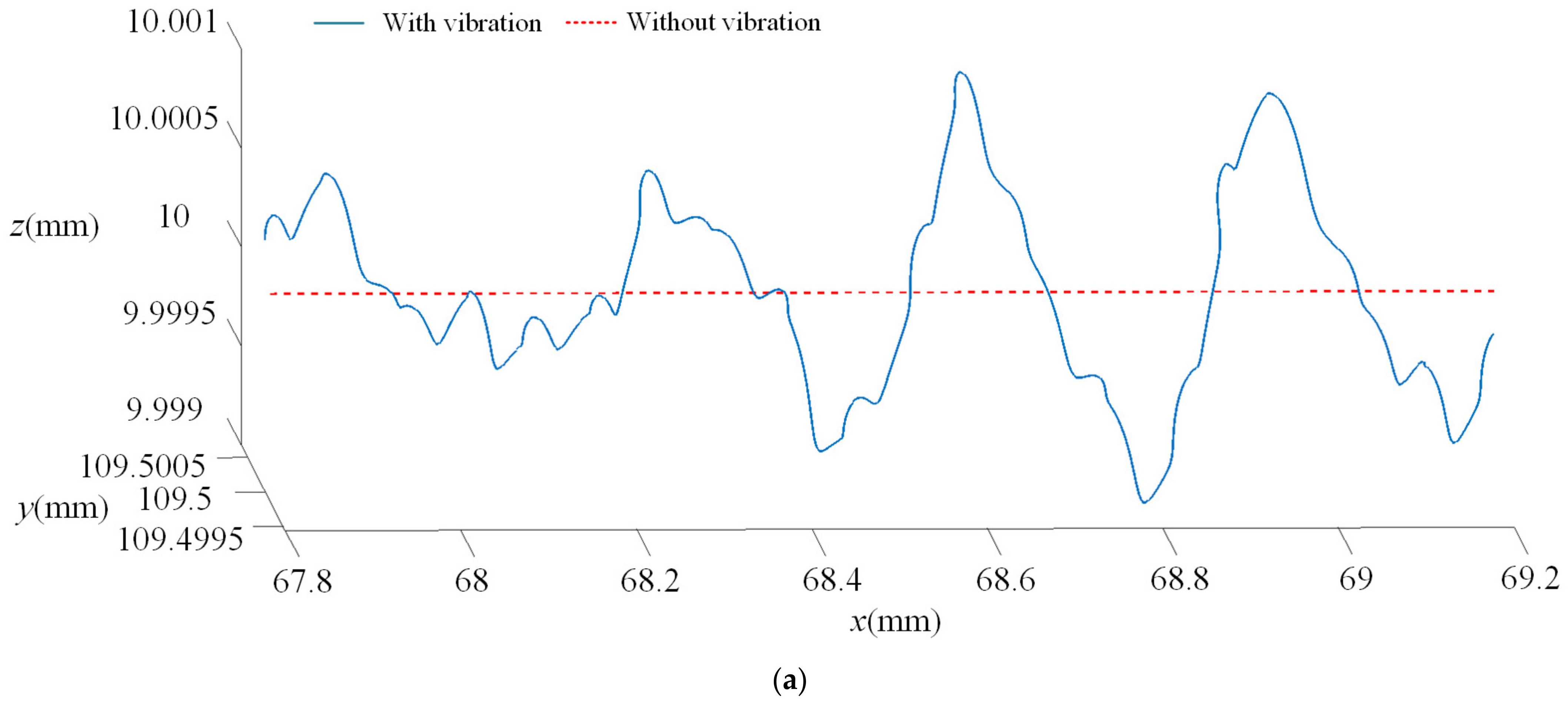
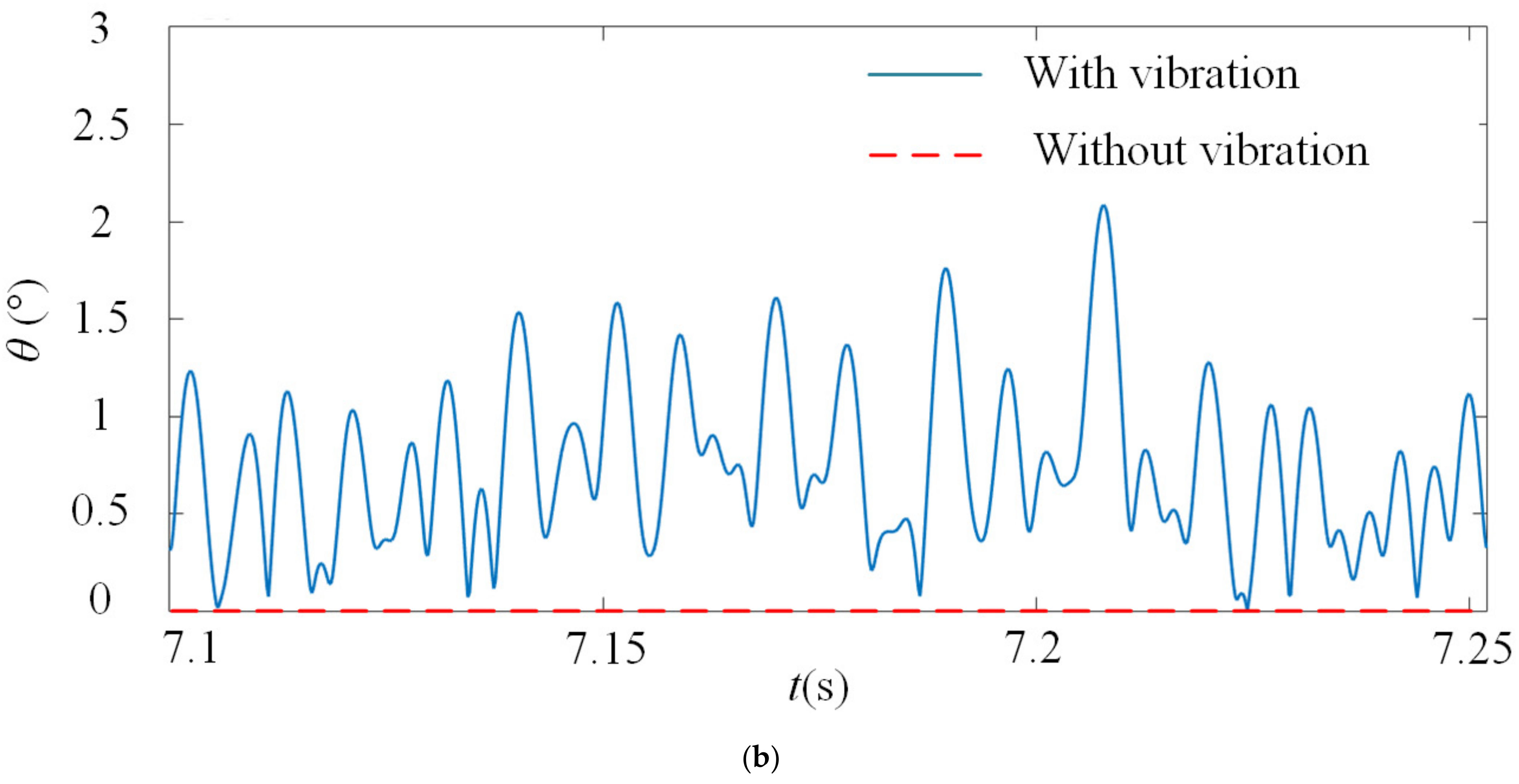
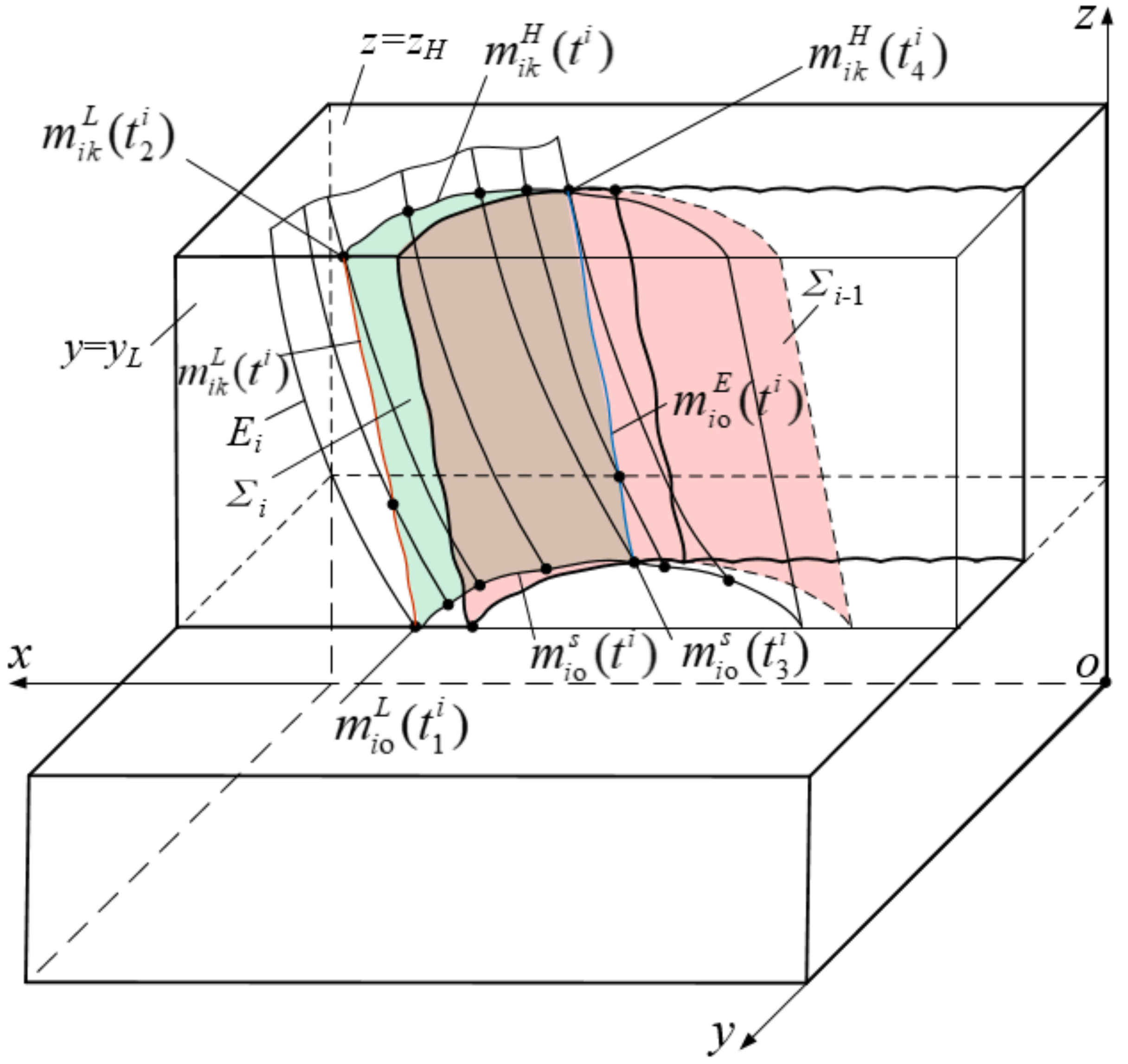
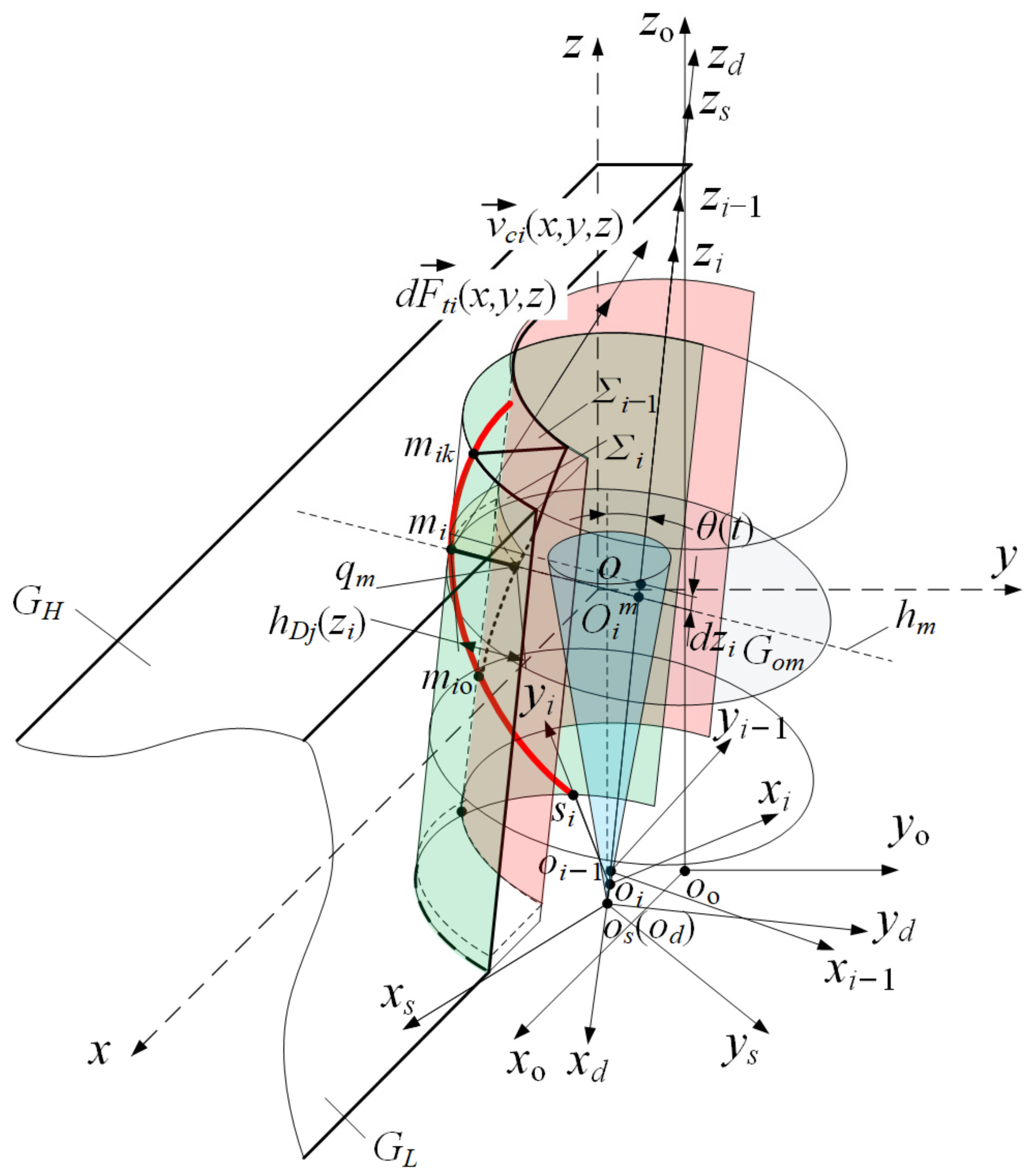
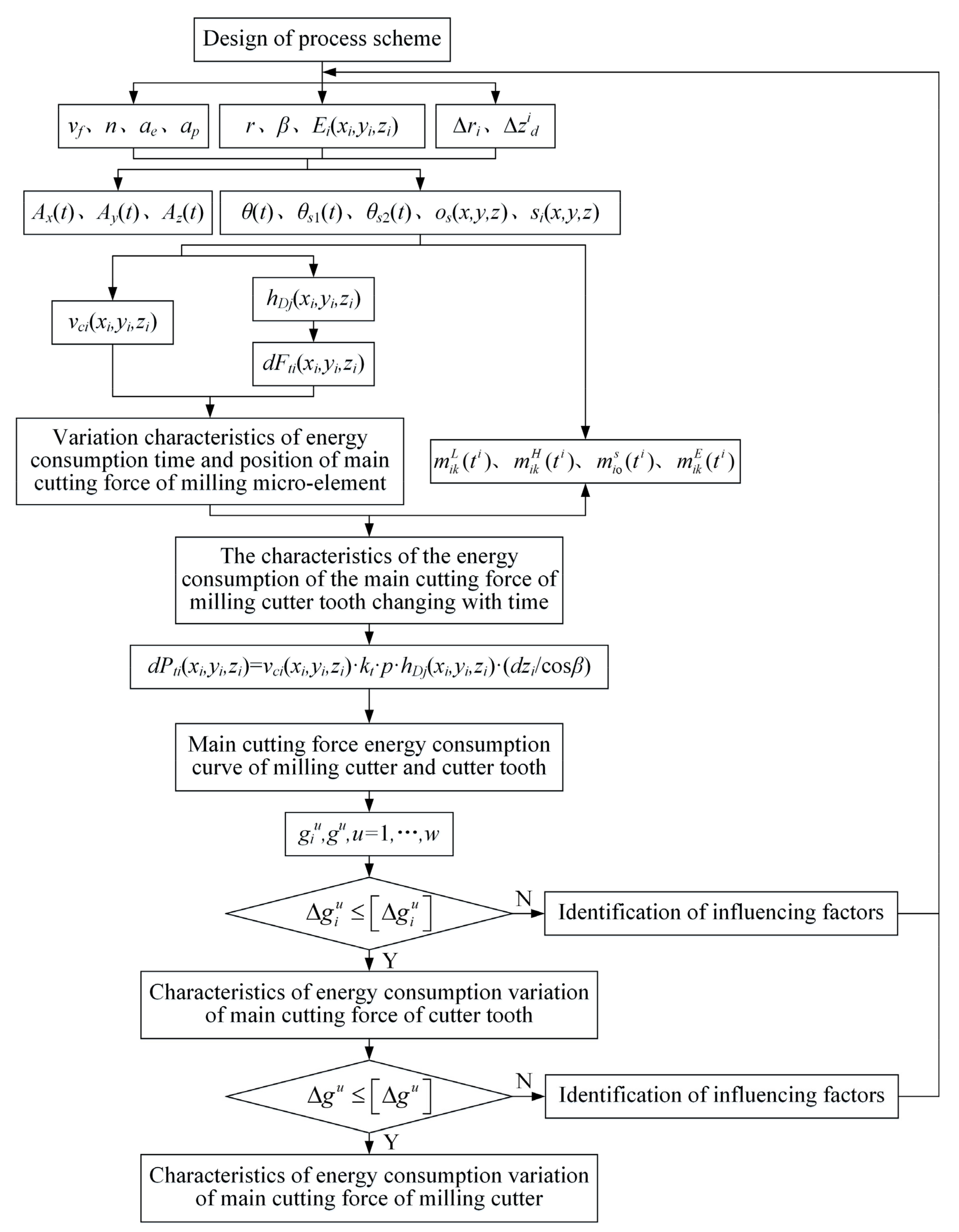
  • The reason the milling cutter posture changes from time to time is milling vibration affects the milling cutter trajectory and bias angle. A model for solving the instantaneous cutting boundary of milling cutter tooth edge under vibration was proposed, the results showed that the milling cutter was displaced due to the influence of milling vibration, besides, the instantaneous cutting boundary was not only affected by the milling vibration during the cutting stage of the current cutter, but also related to the instantaneous pose of the adjacent previous cutter tooth.
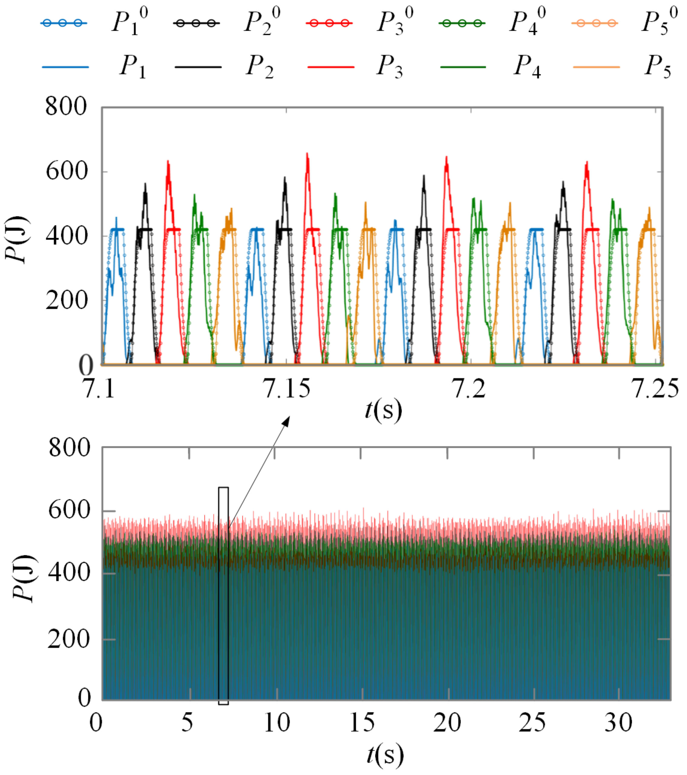
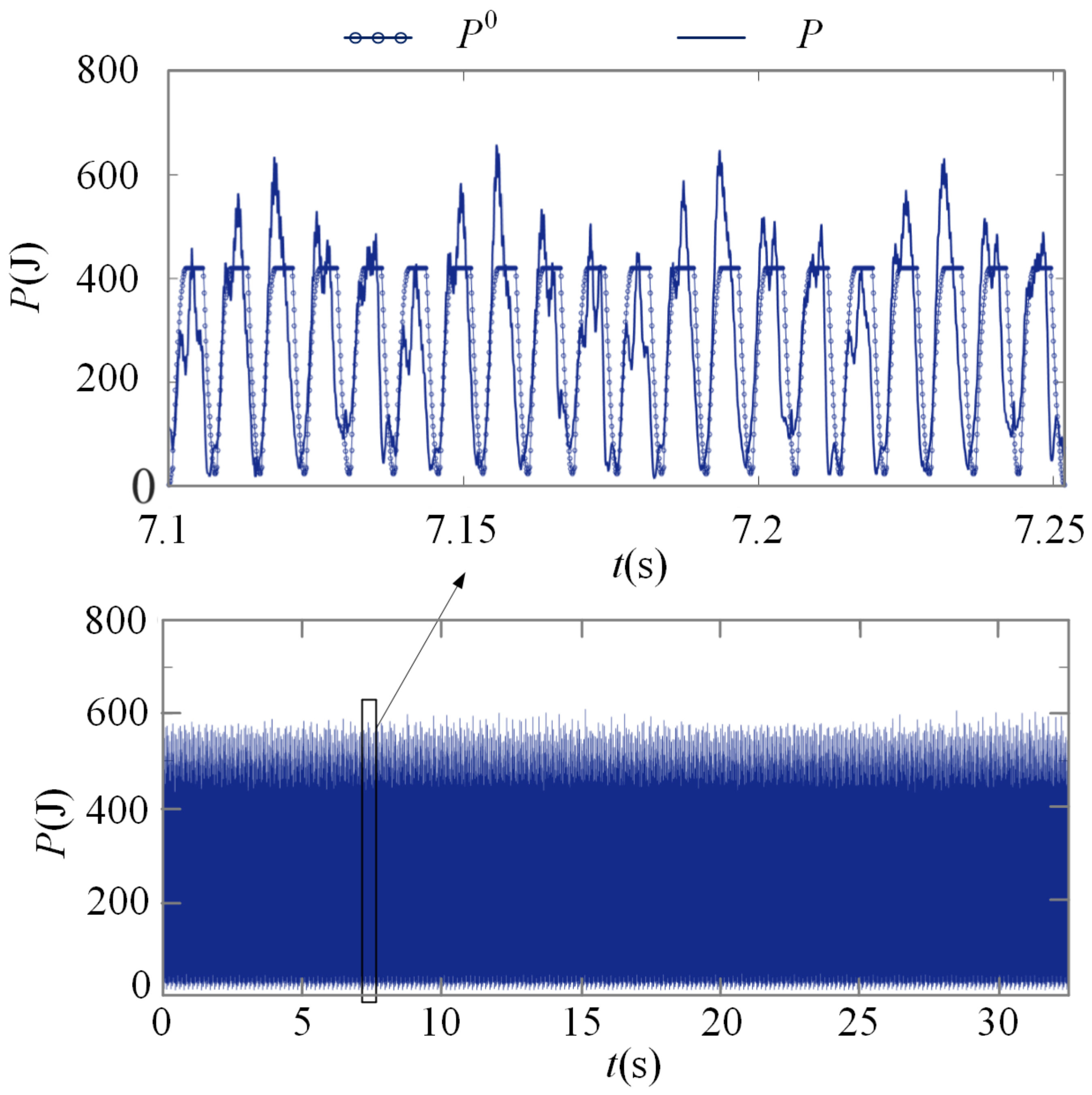
  • The energy consumption distribution function of instantaneous main cutting force of the cutter teeth was constructed. The analysis results of energy consumption distribution showed that, the variation diversity of the instantaneous cutting speed vector, instantaneous main cutting force vector and instantaneous cutting layer parameters were affected by cutter tooth error and milling vibration. The instantaneous main cutting force energy consumption of each cutter tooth showed obvious differences in the aspects of peak value and changing cycle.
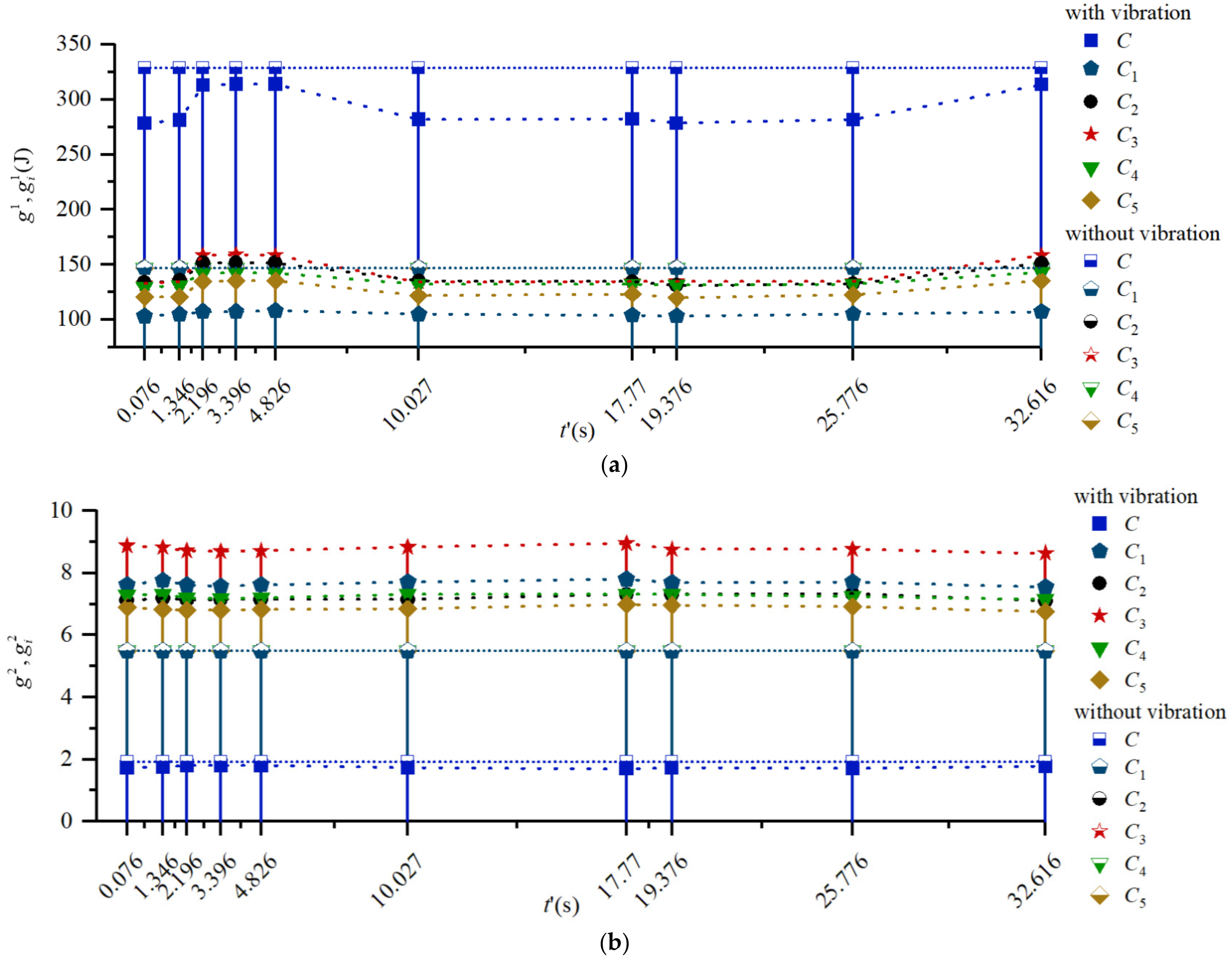
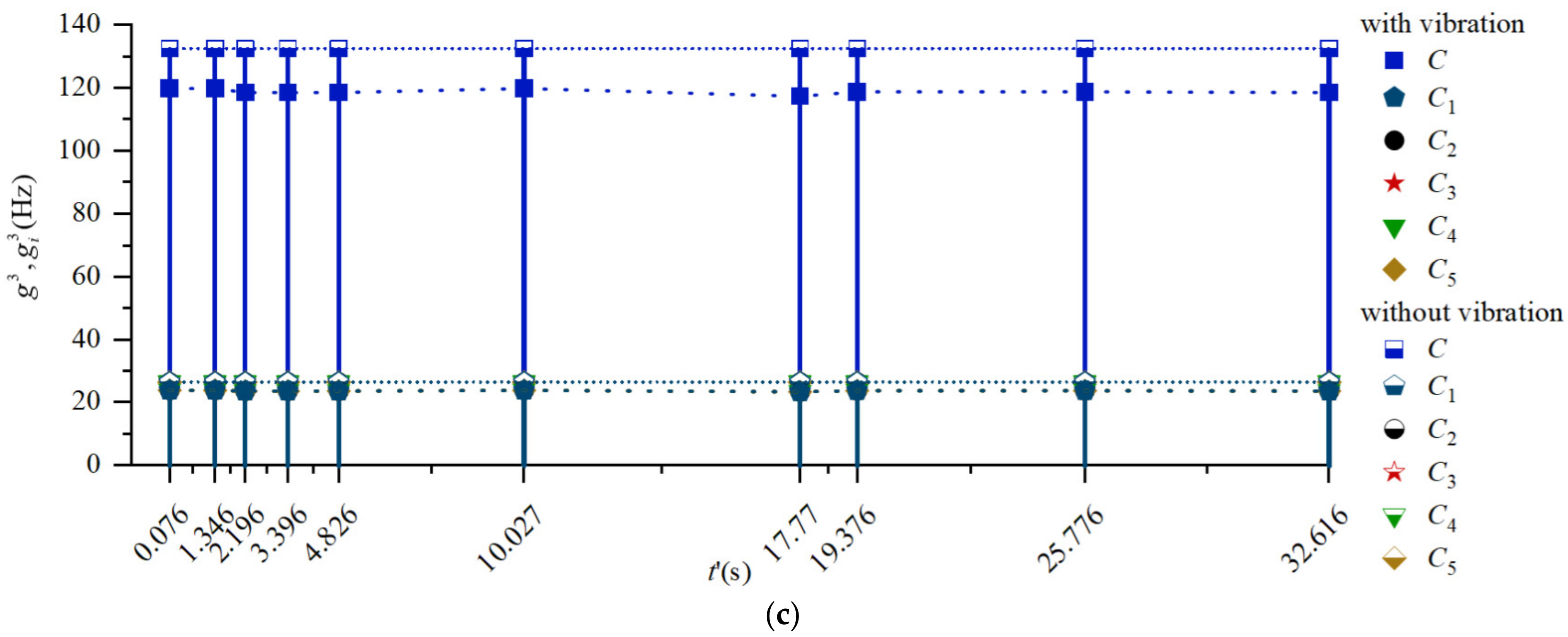
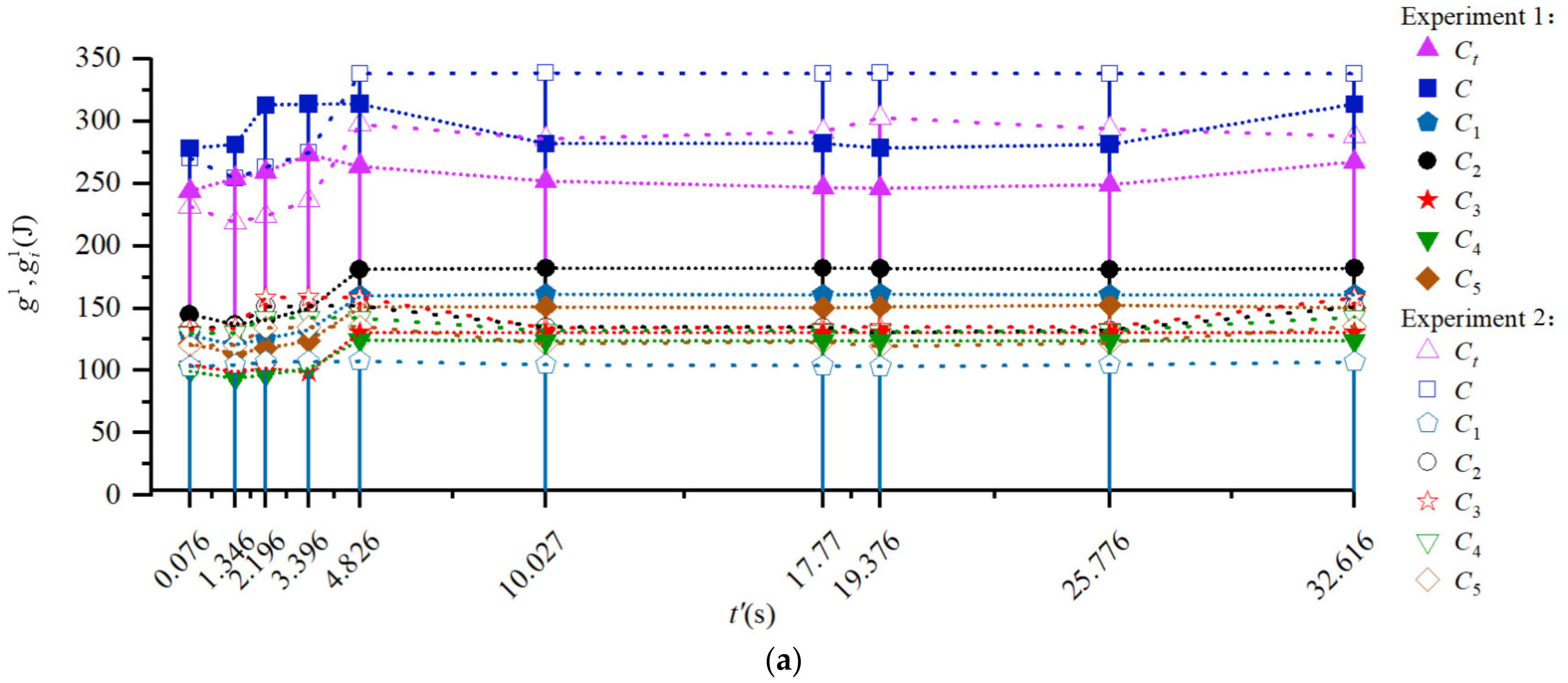
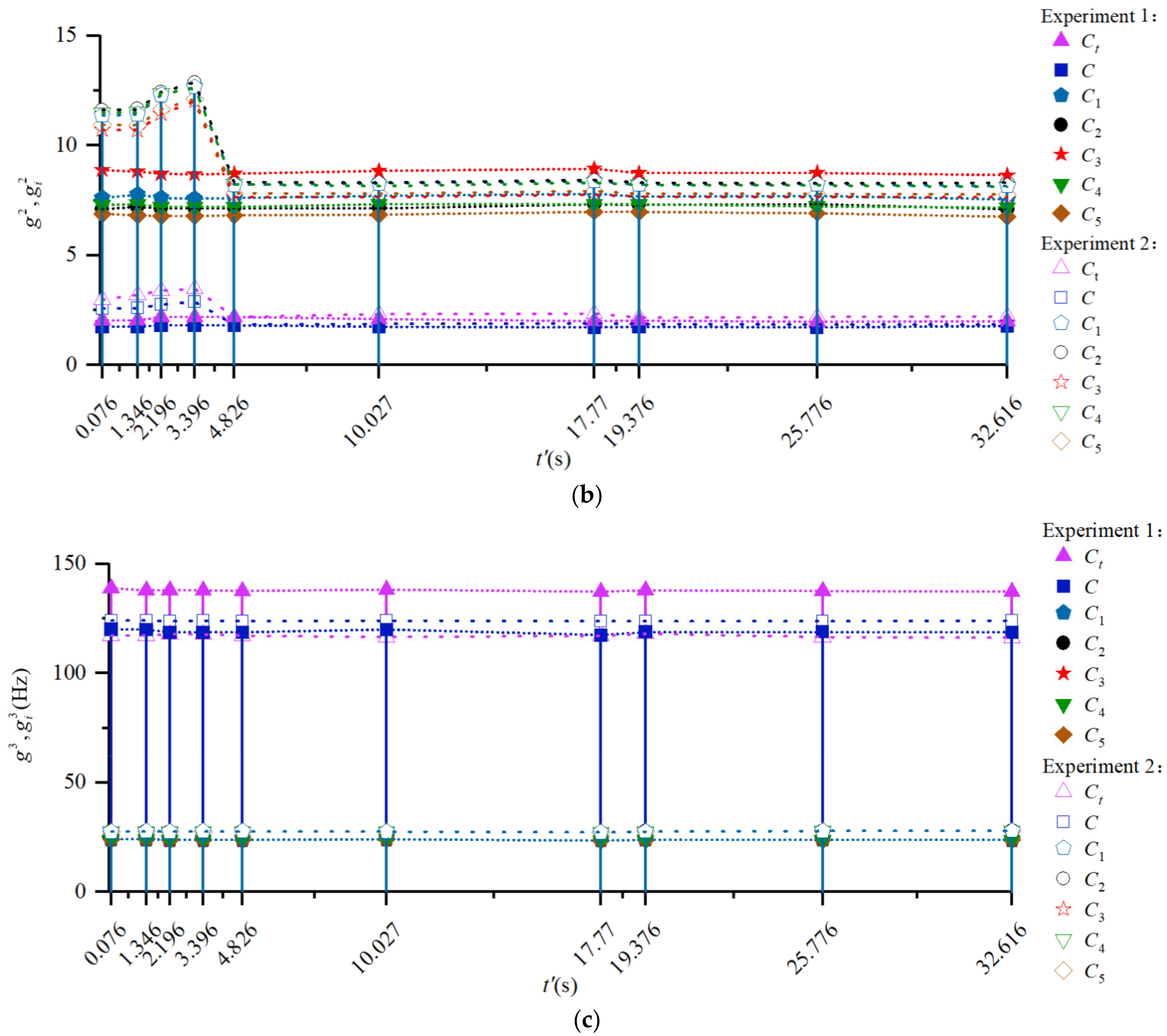
  • A method for identifying the dynamics of the energy consumption of the main cutting force of the milling cutter was proposed. The identification results showed that, the instantaneous energy consumption of main cutting force show dynamic changes mainly in its root mean square, while the kurtosis and changing frequency does not change obviously.
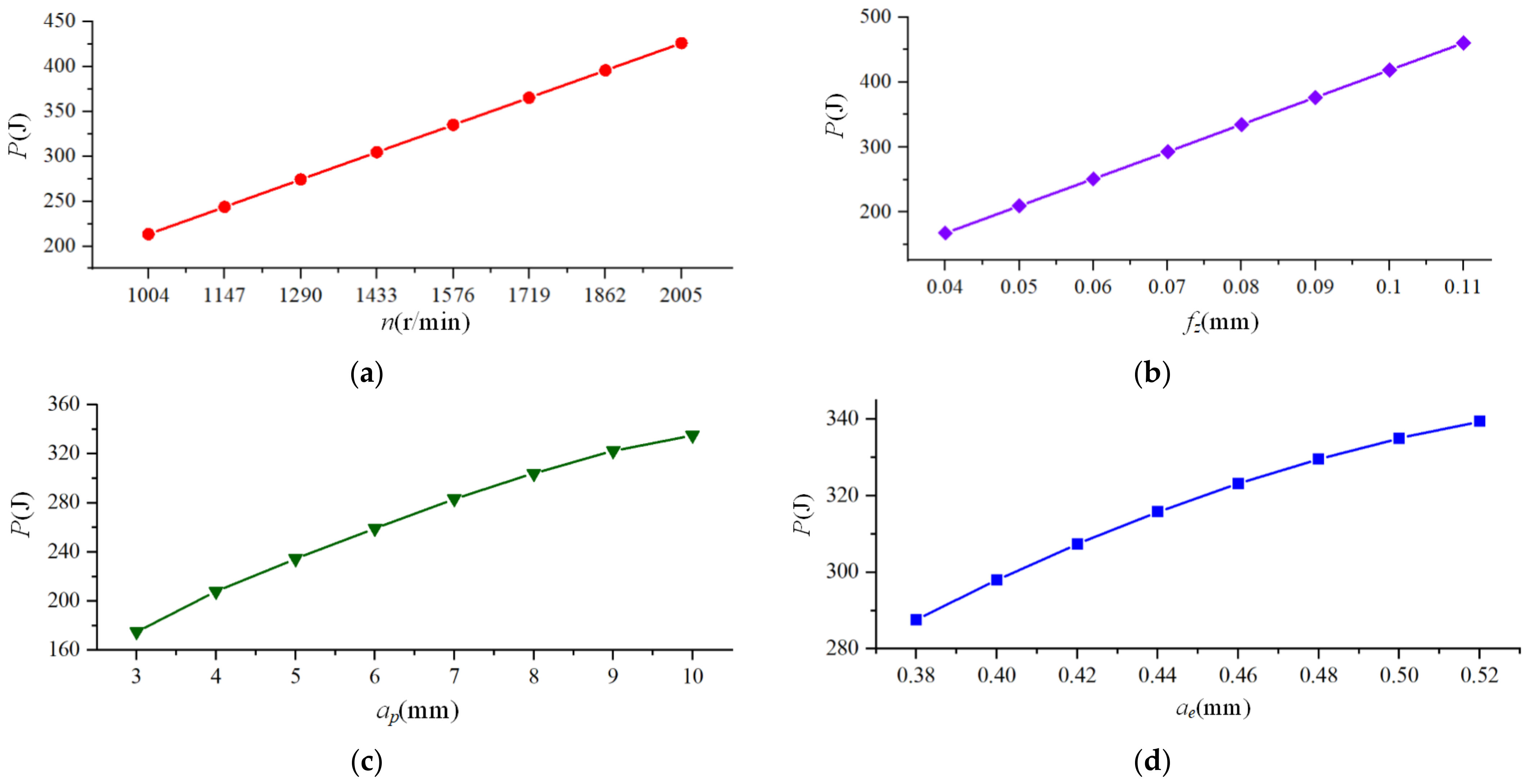
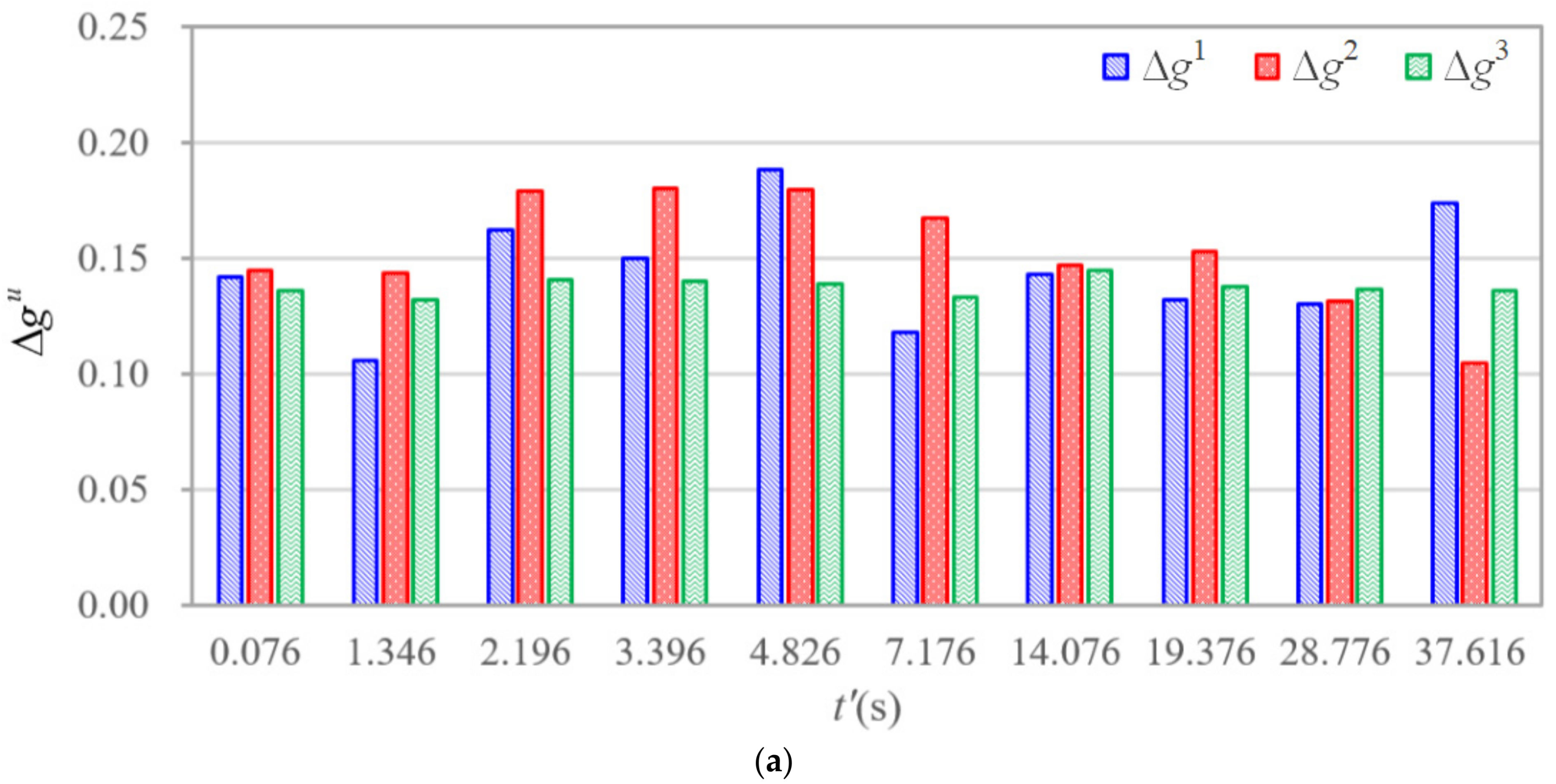
  • The analysis results of the main cutting force energy consumption responses showed that the energy consumption of the instantaneous main cutting force of the milling cutter were sensitive to the process design variables such as the speed of the milling cutter, the feed per tooth and the tooth error. The validation results of the proposed energy consumption model showed that, the relative errors between the calculation and experimental results were less than 20%, which proved the accuracy of the proposed model.

Author Contributions

Conceptualization, B.J. and H.L.; methodology, B.J. and H.L.; software, H.L. and L.F.; validation, L.F. and P.Z.; investigation, H.L.; resources, P.Z.; data curation, H.L. and L.F.; writing—original draft preparation, H.L.; writing—review and editing, H.L. and L.F. and P.Z.; supervision, B.J. and P.Z.; project administration, B.J.; funding acquisition, B.J. All authors have read and agreed to the published version of the manuscript.

Funding

This research was funded by National Nature Science Foundation of China, 51875145 and Nature Science Foundation of Heilongjiang Province of China, ZD2020E008.

Institutional Review Board Statement

Not applicable.

Informed Consent Statement

Not applicable.

Conflicts of Interest

The authors declare no conflict of interest.

References

  1. Huang, Z.T.; Yang, J.; Zhang, C.Y.; Zhou, Z.H.; Xie, Y.; Lin, W.W. Energy consumption-oriented numerical control milling process modeling and parameter optimization. Int. J. Chin. J. Mech. Eng. 2016, 27, 9. [Google Scholar]
  2. Jiang, B.; Zhang, T.; Zhao, P.; Zhao, J.F. Dynamic milling force model for a milling cutter under vibration. Int. J. Adv. Manuf. Technol. 2020, 109, 1–21. [Google Scholar] [CrossRef]
  3. Zhang, T.; Liu, Z.Q.; Sun, X.D.; Xu, J.X.; Dong, L.L.; Zhu, G.L. Investigation on specific milling energy and energy efficiency in high-speed milling based on energy flow theory. Energy 2020, 192, 116596. [Google Scholar] [CrossRef]
  4. Zhang, X.; Liu, F.; Liu, P. The energy efficiency acquisition method of the machining process of the tool workpiece double-rotational motion machine tool. Int. J. Chin. J. Mech. Eng. 2018, 489, 1098–1107. [Google Scholar]
  5. He, Y.; Tian, X.; Li, Y.; Wang, S.; Sutherland, J.W. Modeling machining energy consumption including the effect of toolpath. Int. J. CIRP J. Manuf. Sci. Technol. 2020, 90, 573–578. [Google Scholar] [CrossRef]
  6. Lv, J.; Tang, R.; Tang, W.; Jia, S.; Liu, Y.; Cao, Y. An investigation into methods for predicting material removal energy consumption in turning. J. Clean Prod. 2018, 193, 128–139. [Google Scholar] [CrossRef] [Green Version]
  7. Shi, K.N.; Ren, J.X.; Wang, S.B.; Liu, N.; Liu, Z.M.; Zhang, D.H.; Lu, W.F. An improved cutting power-based model for evaluating total energy consumption in general end milling process. J. Clean Prod. 2019, 231, 1330–1341. [Google Scholar] [CrossRef]
  8. Zhang, X.; Zhao, W. Research on integrated modeling of multi-axis simultaneous milling machining dynamics of CNC machine tools. Chin. J. Mech. Eng. 2020, 56, 1. [Google Scholar]
  9. Bin, J.; Lili, F.; Peiyi, Z.; Zhigang, W.; Junfeng, Z. Identification method for the dynamic distribution characteristics of machining errors in high energy efficiency milling. Int. J. Adv. Manuf. Technol. 2022, 118, 255–274. [Google Scholar] [CrossRef]
  10. Utsumi, K.; Shichiri, S.; Sasahara, H. Determining the effect of tool posture on cutting force in a turn milling process using an analytical prediction mode. Int. J. Mach. Tools Manuf. 2019, 150, 103511. [Google Scholar] [CrossRef]
  11. Jun, M.B.G.; Goo, C.; Malekian, M.; Park, S.S. A new mechanistic approach for micro end milling force modeling. J. Manuf. Sci. Eng. 2012, 134, 925–933. [Google Scholar] [CrossRef]
  12. Warsi, S.S.; Zahid, T.; Elahi, H.; Liaqait, R.A.; Bibi, S.; Gillani, F.; Ghafoor, U. Sustainability-Based Analysis of Conventional to High-Speed Machining of Al 6061-T6 Alloy. Int. J. Appl. Sci. 2021, 11, 9032. [Google Scholar] [CrossRef]
  13. Cai, S.J.; Yao, B.; Feng, W.; Cai, Z.Q. An improved cutting force prediction model in the milling process with a multi-blade face milling cutter based on FEM and NURBS. Int. J. Adv. Manuf. Technol. 2019, 104, 2487–2499. [Google Scholar] [CrossRef]
  14. Wan, M.; Wen, D.Y.; Ma, Y.C.; Zhang, W.H. On material separation and cutting force prediction in micro milling through involving the effect of dead metal zone. Int. J. Mach. Tools Manuf. 2019, 146, 103452. [Google Scholar] [CrossRef]
  15. Wang, Q.; Zhang, D.; Chen, B.; Zhang, Y.; Wu, B. Energy Consumption Model for Drilling Processes Based on Cutting Force. Int. J. Appl. Sci. 2019, 9, 4801. [Google Scholar] [CrossRef] [Green Version]
  16. Zhang, Y.; Li, S.; Zhu, K. Generic instantaneous force modeling and comprehensive real engagement identification in micro-milling. Int. J. Mech. Sci. 2020, 176, 105504. [Google Scholar] [CrossRef]
  17. Li, C.; Zhu, Y.; Li, L. Energy efficiency-oriented multi-objective optimization model of CNC milling parameters. Int. J. Chin. J. Mech. Eng. 2016, 52, 10. [Google Scholar] [CrossRef]
  18. Liu, Z.; Guo, Y.; Sealy, M.; Liu, Z. Energy consumption and process sustainability of hard milling with tool wear progression. Int. J. Mater. Process. Technol. 2016, 229, 305–312. [Google Scholar] [CrossRef]
  19. He, K.; Tang, R.; Jin, M. Pareto fronts of machining parameters for trade-off among energy consumption, cutting force and processing time. Int. J. Prod. Econ. 2017, 185, 113–127. [Google Scholar] [CrossRef]
  20. Wang, L.; Meng, Y.; Ji, W.; Liu, X. Cutting energy consumption modelling for prismatic machining features. Int. J. Adv. Manuf. Technol. 2019, 103, 1654–1667. [Google Scholar] [CrossRef]
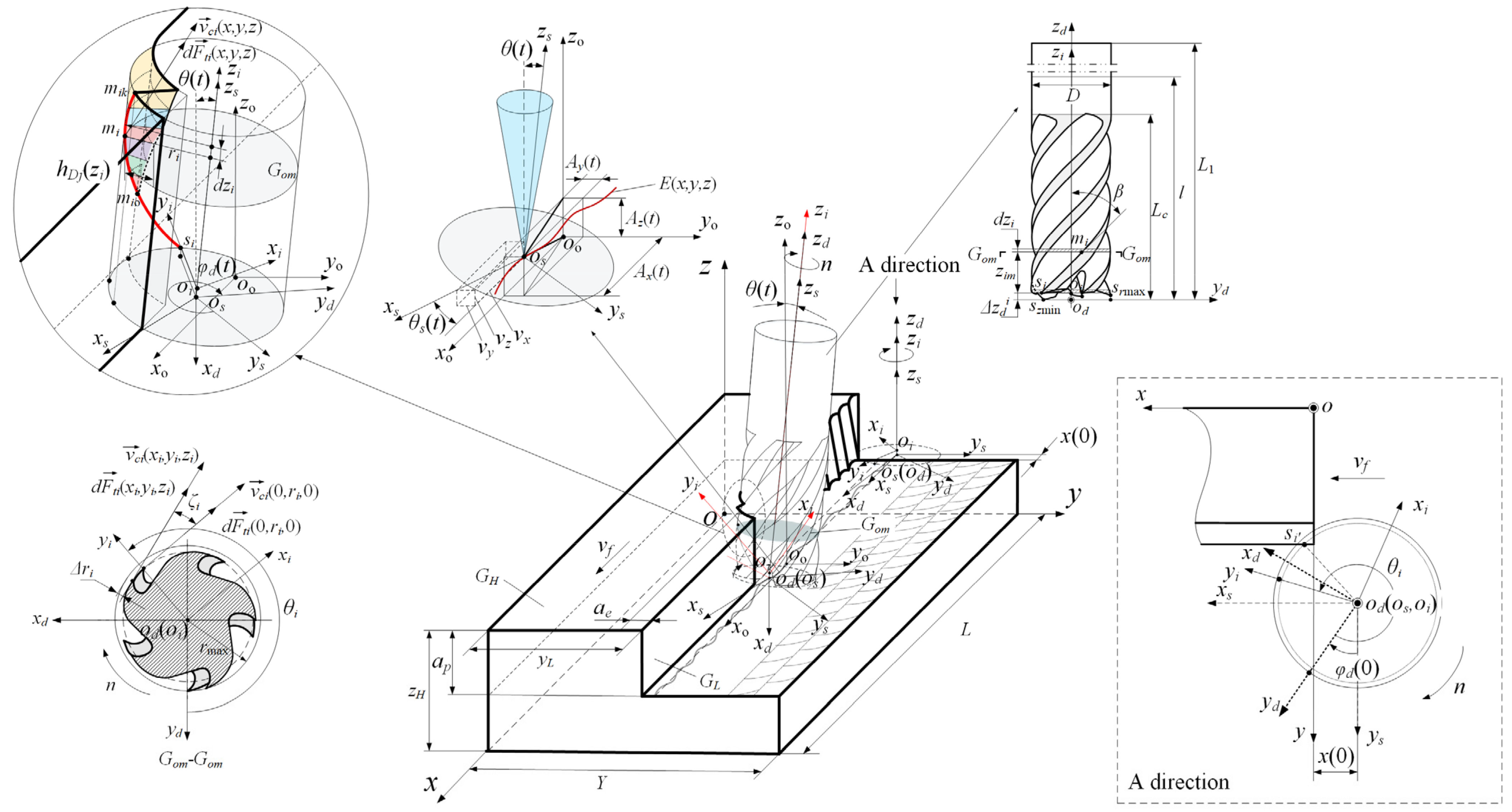
Figure 1. Instantaneous cutting behavior of the cutter under vibration.
Applsci 12 01531 g001
Figure 2. Trajectory and the bias angle of the milling cutter, (a) trajectory of the milling cutter, (b) bias angle of the milling cutter.
Applsci 12 01531 g002aApplsci 12 01531 g002b
Figure 3. Instantaneous engagement between the cutting edge and the workpiece.
Applsci 12 01531 g003
Figure 4. Instantaneous cutting speed and main cutting force of the cutter tooth cutting edge.
Applsci 12 01531 g004
Figure 5. Milling cutter structure and cutter tooth serial number.
Applsci 12 01531 g005
Figure 6. Milling vibration acceleration signal and selection of cutting stage.
Applsci 12 01531 g006
Figure 7. Time–domain curve of the main cutting force energy consumption.
Applsci 12 01531 g007
Figure 8. Main cutting force energy consumption of the milling cutter.
Applsci 12 01531 g008
Figure 9. Time–frequency parameters of main cutting force energy consumption with/without milling vibration and cutter tooth errors, (a) root mean square, (b) kurtosis, (c) dominant frequency.
Applsci 12 01531 g009aApplsci 12 01531 g009b
Figure 10. Identification method for the dynamics of the main cutting force energy consumption of the milling cutter and its cutter tooth.
Applsci 12 01531 g010
Figure 11. Milling vibration acceleration signal of the scheme 2.
Applsci 12 01531 g011
Figure 12. Results of main cutting force energy consumption of milling cutter and cutter teeth of scheme 2, (a) energy consumption of cutter teeth, (b) energy consumption of milling cutter.
Applsci 12 01531 g012
Figure 13. Installation of cutting force measurement device and measured main cutting force in experiments.
Applsci 12 01531 g013
Figure 14. Experimental results of main cutting force energy consumption of milling cutter with time, (a) experimental result of energy consumption of scheme 1, (b)experimental result of energy consumption of scheme 2.
Applsci 12 01531 g014aApplsci 12 01531 g014b
Figure 15. Response and verification of time–frequency of main cutting force energy consumption of the milling cutter, (a) root mean square, (b) kurtosis, (c) dominant frequency.
Applsci 12 01531 g015aApplsci 12 01531 g015b
Figure 16. Influence of process parameters on main cutting force energy consumption of milling cutter, (a) spindle rotational speed, (b) feed per tooth, (c) cutting depth, (d) cutting width.
Applsci 12 01531 g016
Figure 17. Relative errors of time–frequency parameters of energy consumption distribution of main cutting force of the milling cutter, (a) relative errors of energy consumption distribution of scheme 1, (b) relative errors of energy consumption distribution of scheme 2.
Applsci 12 01531 g017aApplsci 12 01531 g017b
Table 1. Explanation of the cutting behavior of the cutter under vibration.
Serial NumbersParametersParameters Explanation
1L, Y, zHThe length, width, and height of the workpiece, respectively.
2o-xyzThe workpiece coordinate. yL is the distance between the workpiece to be processed side elevation GL and the xoz plane along the y axis.
3DThe diameter of the milling cutter.
4βThe helix angle of the milling cutter.
5LcThe axial length of the cutting edge of the milling cutter.
6lThe overhang of the milling cutter.
7L1The total length of the milling cutter.
8szminThe lowest cutter tip in the axial direction.
9srmaxThe cutter tip with the largest radius of the milling cutter.
10od-xdydzdThe milling cutter structure coordinate system, od is the center of rotation of the lowest cutter tip in the axial direction; the xd axis is parallel to the direction of the cutting speed at the maximum cutter tip of the radius; the yd axis is parallel to the radial direction of the cutter tip with the maximum radius; zd axis is the rotation axis of the milling cutter and points to the cutter shank.
11siThe cutter tip of the ith cutter tooth.
12riThe rotation radius of the ith cutter tooth.
13ΔriThe radial error of the ith cutter tooth.
14ΔzdiThe axial error of ith cutter tooth.
15oi-xiyiziThe cutter tooth coordinate system, oi is the rotation center of the cutter tip, yi axis is the direction through the origin oi points to the cutter tip, and zi axis is parallel to zd.
16θiThe included angle between yi axis and yd axis.
17nThe rotational speed of the milling cutter.
18vfThe nominal feed speed of the milling cutter.
19aeThe cutting width of the milling cutter.
20apThe cutting depth of the milling cutter.
21oo-xoyozoThe milling cutter cutting coordinate system without vibration.
22Ax(t), Ay(t), Az(t)The vibration displacement of the milling cutter in three directions of x, y, and z, respectively.
23os-xsyszsThe milling cutter cutting coordinate system after the bias of oo-xoyozo caused by milling vibration, oo coincides with od, the xs axis is the direction of the tangent vector of the milling cutter center od motion trajectory, and the zs axis coincides with the zd axis.
24os(x, y, z)The motion trajectory of the coordinate origin os.
25vx, vy, vzThe components of the tangent vector of os(x, y, z) along the x axis, y axis, and z axis, respectively.
26θ(t)The angle between zs axis and zo axis at time t.
27θs(t)The angle between xs axis and xo axis.
28φsi(t)The included angle between yi axis and ys axis in xsosys plane.
29x(0)The distance between coordinate origin os and coordinate origin o along x axis when t is 0.
30siThe first tip point of cutting into the workpiece.
31miThe point on the cutting edge of the ith cutter tooth.
32ζiThe lag angle of mi relative to the tip point of the ith cutter tooth.
33zimThe axial height of mi in the ith cutter tooth coordinate system.
34dziThe axial height of milling micro-element of mi.
35PomThe main section where mi is located.
36mioThe lower boundary of the ith cutter tooth instantaneous cutting.
37mikThe upper boundary of the ith cutter tooth instantaneous cutting.
38hDj(zi)The instantaneous cutting layer thickness of mi.
39φd(0)The initial cutting time of the milling cutter.
40φd(t)The instantaneous angle between yd axis and ys axis in xsosys plane.
41 d F t i ( x , y , z ) The cutting speed vector of a point on the cutting edge in the o-xyz
42 v c i ( x , y , z ) The cutting speed vector of a point on the cutting edge in the o-xyz.
43 d F t i ( x i , y i , z i ) The main cutting force vector at a point on the cutting edge in the oi-xiyizi.
44 v c i ( x i , y i , z i ) The cutting speed vector of a point on the cutting edge in the oi-xiyizi.
45 d F t i ( 0 , r i , 0 ) The main cutting force vector at the tip point of the ith cutter tooth.
46 v c i ( 0 , r i , 0 ) The cutting speed vector at the tip point of the ith cutter tooth.
Table 2. Milling experimental parameters.
Cutter
Tooth
Error
Cutter Tooth NumberCutting Parameters
i = 1i = 2i = 3i = 4i = 5n
(rpm)
fz
(mm/z)
ap
(mm)
ae
(mm)
Δzid
(mm)
0.0510.0080.0000.0120.02215760.073100.5
Δri
(mm)
0.0000.0040.0010.0100.018
Table 3. Milling experimental parameters and cutter tooth error of the scheme 2.
Cutter
Tooth
Error
Cutter Tooth NumberCutting Parameters
i = 1i = 2i = 3i = 4i = 5n
(rpm)
fz
(mm/z)
ap
(mm)
ae
(mm)
Δzid
(mm)
0.0010.0000.0090.0130.00417190.067100.5
Δri
(mm)
0.0290.0100.0180.0390.000
Publisher’s Note: MDPI stays neutral with regard to jurisdictional claims in published maps and institutional affiliations.

