1. Introduction
Underground mines commonly use orepass systems as a safe and economic method to transport blasted ore, i.e., broken rocks, between production levels. In each orepass, a steel grate, called a grizzly, is used to control the size of the material entering the orepass. Material that is too large cannot pass through the grizzly and has to be broken using impact hammers. Impact hammers, also known as rock breakers, rock-breaking manipulators, rock-breaking hammers, or pedestal-mounted breaker booms, consist of an hydraulic arm with 4 degrees of freedom (rotation, lift, tilt, and breaker joints) powered with a hydraulic impact hammer as an end-effector.
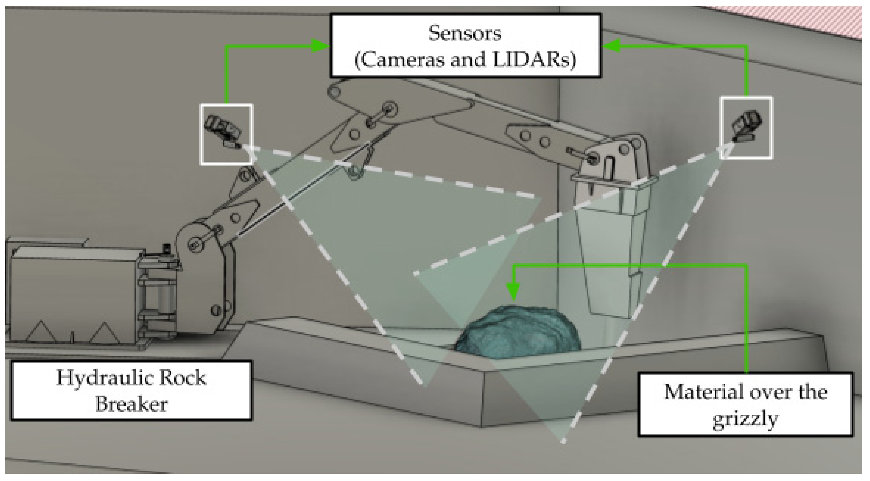
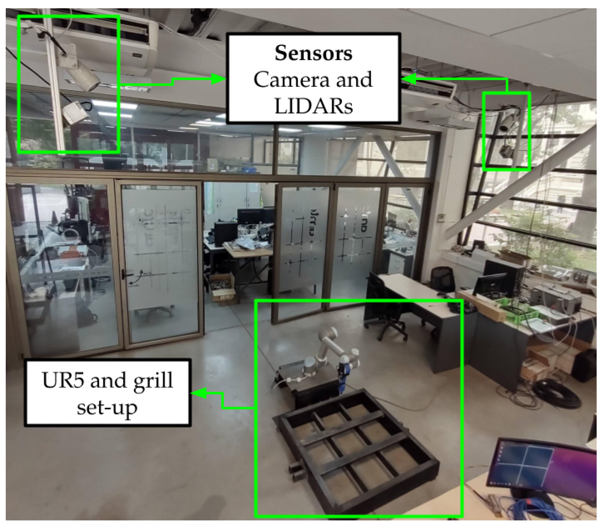
Figure 1 shows a diagram of the operating environment of an impact hammer. It shows a possible arrangement of sensors to obtain data from the material over the grizzly.
In modern mining facilities, impact hammers are usually tele-operated from a control room located in a safe place, away from the operation area. Under this schema, the operator actuates the electro-valves that control the hydraulic system using joysticks and buttons via a data network. To compensate for this lack of direct vision of the environment, cameras and video transmission equipment are often installed in the operation area. However, the data network and video stream encoding and decoding introduce a delay, or latency, between what the operator sees, and what is actually happening, which adds difficulties to tele-operation [
1,
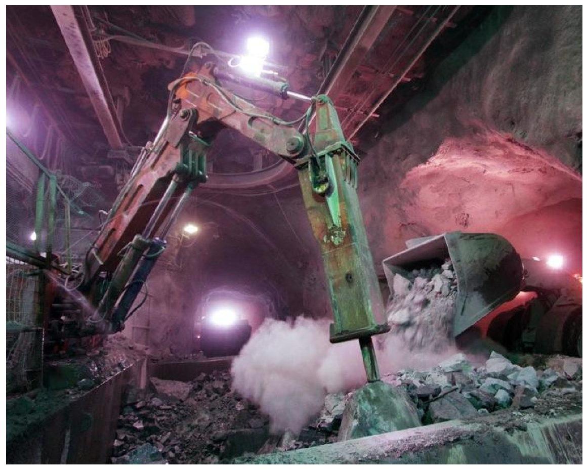
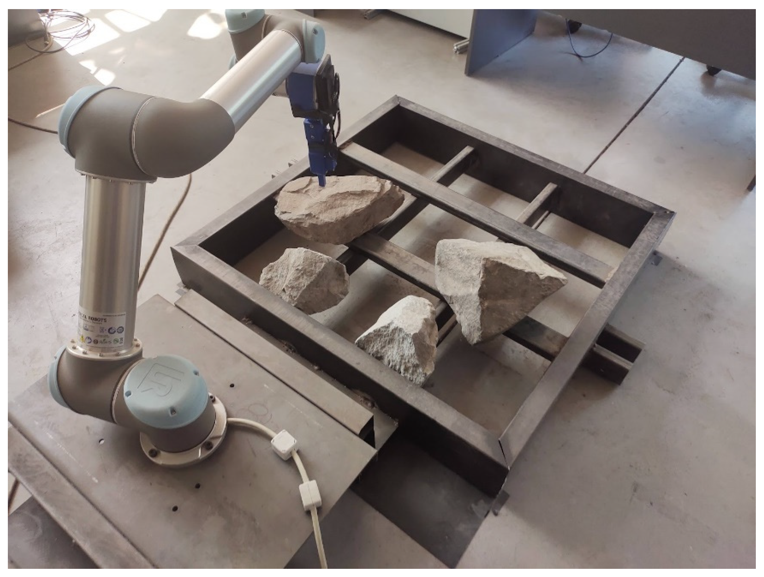
2]. Due to the mentioned latency, the poor visibility of the environment, and the used 2D visualization interfaces, hammer tele-operation requires highly skilled operators that are trained to deal with these two phenomena. A typical operating environment can be observed in
Figure 2. This figure shows a frontal loader dumping material onto the grizzly, and a tele-operated impact hammer fragmenting rocks.
Normally an operator handles more than one impact hammer, and due to the intermittent nature of this operation, sometimes the operator does not notice immediately that an orepass is being obstructed. This often causes the fragmentation process to take longer than it should because it is more difficult to clear a stoked orepass than a few rocks over the ore pass’s grizzly, generating a delay in the mine’s production chain. In addition, the described, standard tele-operation of impact hammers does not allow the operator to properly perceive the actions of the impact hammer in the environment because its sensors are limited to visual cameras that provide a 2D representation of the environment. This issue may cause damage to the impact hammer, for example, when the tool is activated without being in contact with the rock, which causes idle strokes in the air, or when the hammer collides with the environment (e.g., with the grizzly). In order to address these drawbacks, assistive tele-operation technology can be used for: (i) Enhancing the operator’s perception by adding other sensing modalities (e.g., range sensors), (ii) notifying the operator every time that an orepass is blocked to have a shorter reaction time, and (iii) giving haptic feedback to the operator to avoid collisions of the hammer’s end-effector with the surrounding environment. Using these improvements, the operator could make better decisions that result in a more precise operation, extended lifetime of the equipment, and higher throughput of the mineral transport system.
There is very little literature related to the automation or tele-operation of impact hammers. According to [
3], previous works concerning the automation or modernization of impact hammers are few. First attempts to automate impact hammers date back to 1998 [
4], and the first tele-operated impact hammer was reported in 2000 [
5].
Most of the reported work addressing tele-operation of impact hammers uses 2D cameras, and in some cases time-of-flight cameras (TOF) or stereo cameras. According to [
3], TOF’s low resolution is insufficient for this task, and stereo cameras obtain a single view of the scene. To the best of our knowledge, there are no previous works using 3D LIDAR (Laser Imaging Detection and Ranging) in this application, nor works reporting the use of haptic devices for the tele-operation of impact hammers.
Regarding the autonomous operation of impact hammers, the reported results are very poor. In [
3], an average success rate of 34% is obtained in the task of breaking rocks, which does not make it possible for the application of this technology in a real mining environment. For this reason, we believe that a good intermediate step to full-automation, which improves the current technology used for the tele-operation of impact hammers, is haptic tele-operation.
In this context, this paper proposes the haptic tele-operation of impact hammers for improving the efficiency of the fragmentation process. The proposed haptic tele-operation system is based on a 3D model of the environment, which is used to estimate repulsion forces that are transferred to the operator via a haptic control device, so that the hammer does not collide with the structures of the mine. The repulsion forces are a function of the distances between the hammer’s end-effector and the environment. The 3D model of the environment is built using point clouds acquired using range sensors, and updated continuously.
The proposed system also allows identifying the oversized boulders deposited on the grizzly and notifying the operator every time the ore pass is blocked. Moreover, thanks to the use of 3D sensors and cameras placed on opposite sides of the hammer (see
Figure 1), it is possible to show the operator the environment from different viewpoints and a 3D model of the rocks to be crushed. With this information, the operator can make better decisions.
We do believe that the use of point clouds for improving tele-operation in mining applications will increase in the following years, thanks to the popularization of 3D scanning sensors, and the availability of libraries for processing this data (e.g., [
6,
7]). Field applications, as the one described here, will use this haptic technology.
In other industries, the use of point clouds (obtained using range sensors) for obtaining haptic feedback in tele-operation applications is not new, although most reported papers describe systems that operate in controlled or semi-controlled environments, which is not the case for underground mining. In ref. [
8], a method of haptic feedback in real time, using streaming point clouds from RGB-D cameras, without using contact sensors and without preprocessing the data, is proposed. The concept of virtual world is used, in which the simulated robot can move freely. In this virtual world, the tip of the virtual effector or HIP (haptic interface point) is related to the movement desired by the user. This effector, in turn, is wrapped in a zone of influence called proxy, which is forbidden to interact with the point cloud. Therefore, if the effector tries to enter the point cloud (or be in a position very close to it), a difference between the position of the virtual effector or HIP with the center of the proxy will be produced. This difference in positions will result in a feedback force vector, which will cause the effector’s motion to change direction. The work described in ref. [
9] is based on the described feedback system, and introduces the concept of delay in tele-operation, where the motion is first performed in virtual space and then executed in the real world. This implementation and testing of the system were performed by teleoperation of a KUKA industrial robot, where the virtual world was created using point clouds obtained with an RGB-D camera. This work confirms that haptic feedbacks increase the operator’s accuracy by reducing the errors in the desired trajectory of the end effector, decreasing the collisions with the environment, and reducing the operation time. In ref. [
10], a haptic system based on distances measured using a stereo camera, is evaluated on a robotic arm used to transport an object without colliding with obstacles. In ref. [
11], a 3D virtual environment is recreated by a Kinect sensor used to calculate haptic forces based on potential fields. The paper evaluates the path generated when operating a robot arm with 7 degrees of freedom.
This paper is organized as follows. In
Section 2, the proposed haptic tele-operation of impact hammers is described.
Section 3 presents results, both in simulation and in reality, which are discussed in
Section 4. Finally, in
Section 5, conclusions of this work are drawn.
2. Haptic Teleoperation of Impact Hammers
2.1. Overall System Architecture
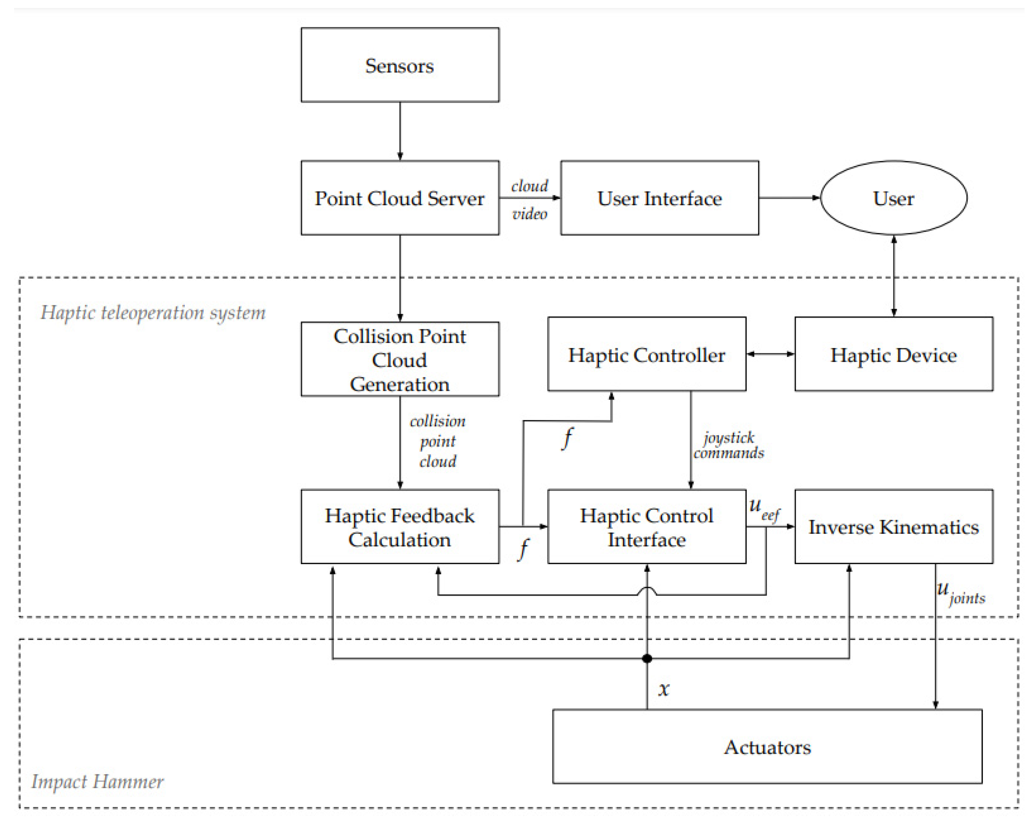
The proposed haptic tele-operation system is composed of eight sub-modules (see
Figure 3). The
Point Cloud Server acquires and merges the data from the two LIDARs, and segments it in three different point clouds, each one corresponding to measurements associated to reflections on the infrastructure, hammer, and material. These point clouds, and the acquired images, are sent to the
User Interface where the different visualization are generated for the user. The
Collision Point Cloud Generation module receives the point clouds and generates a so-called
collision point cloud, which represents the points in the space to be avoided during tele-operation. The
Haptic Feedback Calculation module estimates possible future collisions using the collision point cloud, the current commands on the end-effector (
ueef), and the state of the hammer’s joints (
x), and it generates haptic feedback information (
f) for the haptic controller and haptic control interface. The
Haptic Controller receives this feedback and generates the haptic force to be applied on the
Haptic Device to alert the user of the limitation of the commands. At the same time, the
Haptic Control Interface receives the control command on the end effector, which is the result of the operator force on the
Haptic Device and the haptic force on the joystick, and the haptic feedback to limit the commands in case of any risky situation, for example, when the operator in spite of the haptic feedback decides to perform a risky task. Finally, these commands are converted from the Cartesian space (
ueef) to the joint space (
ujoints) using the
Inverse Kinematics of the machine to handle the articulation actuators directly.
2.2. Sensors
Sensors are located above the grizzly, on opposite sides, to generate complementary points of view of the working space (see
Figure 1), and to provide a better representation of the material over the grizzly when both views are combined. In each side, a 3D LIDAR and camera are used. These sensors provide a streaming of point clouds and images. Point clouds are used to build a 3D model of the environment, and images are used for visualization purposes.
2.3. Point Cloud Server
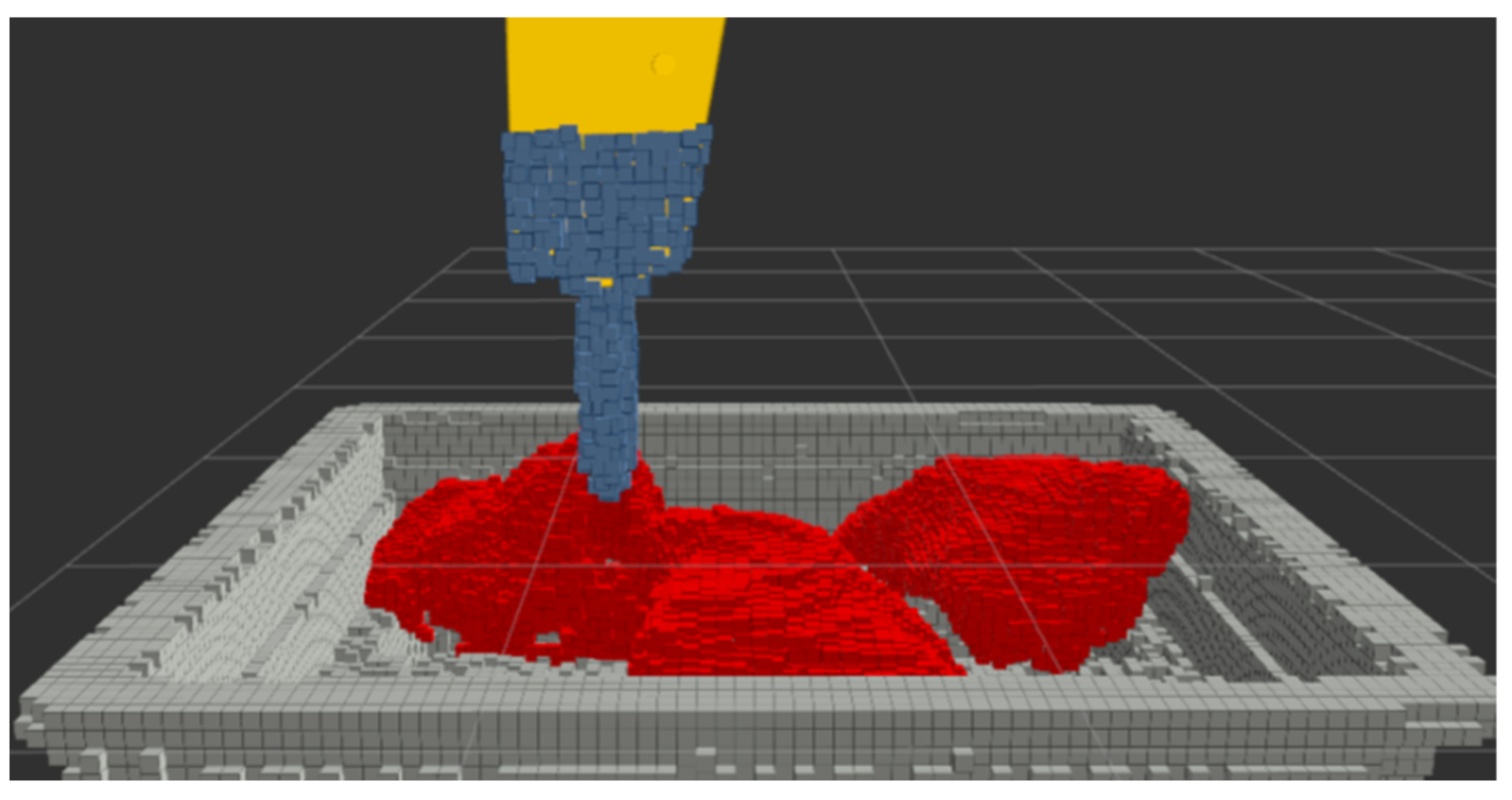
This module first merges the point clouds acquired by the different 3D LIDARs into a single cloud. This point cloud is down sampled to generate a voxel grid representation of the space. Then, all the voxel grid points are separated in three different categories (see
Figure 4):
Environment points that include all points that do not change in the operation of the system (e.g., point of the floor, points of the grizzly, and point over other parts of the structure of the mine). These points are used to build the 3D model of the environment;
Hammer points that correspond to the points generated by the LIDAR’s reflections on the impact hammer, which are generated when certain parts of the hammer are positioned in the scanning area of the sensors;
Material points that correspond to any other point detected, which should correspond to the material over the grizzly.
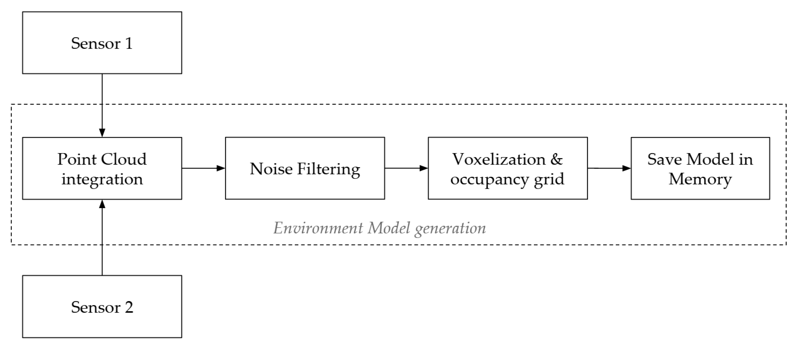
During the system’s initialization, the environment model is generated by successively integrating point clouds from the environment, without considering the ones corresponding to material or the impact hammer. This results in a very dense point cloud that is first filtered for deleting isolated points that could be generated by noise on the sensors. Once the noise has been eliminated, the cloud is voxelized in 3D square voxels, reducing the number of point and maintaining the occupancy information of the environment in the space. Finally, this cloud is saved as the environment model.
Figure 5 shows the main modules of the described process. Sensors 1 and 2 correspond to the 3D LIDARs used to capture the model of the environment through point clouds. The
Point Cloud Integration module corresponds to the process of joining the point clouds of both sensors and performing the task of integrating these successive point clouds over time. The
Noise Filtering module is responsible for removing noise. The
Voxelization & Occupancy Grid module is in charge of voxelizing the point cloud in order to eliminate repeated points and to show the occupancy of the space. And finally, the
Save Model in Memory module stores the resulting point cloud in memory for later use.
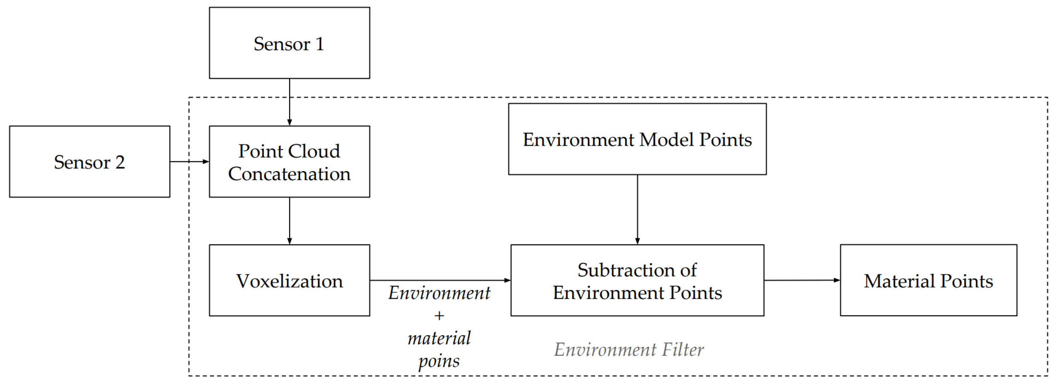
During operation, the environment model is used for determining the points that belong to the material model and hammer model. In each iteration, each new point cloud is voxelized and contrasted with the point cloud of the environment model. This comparison allows to subtract the points belonging to the environment. Once subtracted from the environment points, the resulting point cloud contain the hammer-points and material-points. Hence, to obtain the material-points, a new filtering process should be performed to subtract the hammer-points. This is done by first estimating the spatial region where the hammer is located, which is obtained using the current state of the hammer’s joints and the kinematic model of the hammer. This way, all those points within this space will be classified as belonging to the hammer and therefore eliminated.
Figure 6 shows the process used to obtain the point cloud of the material. Sensors 1 and 2 correspond to the 3D LIDARs used to capture the working environment. The
Point Cloud Concatenation module is in charge of joining the point clouds coming from both sensors. The
Voxelization module is in charge of voxelizing the point cloud resulting from the union of both sensors, thus eliminating repeated points. The
Environment Model Points corresponds to the point cloud stored in memory, which only contains points corresponding to the grizzly. The
Subtraction of Environment Points module compares the current point cloud with the point cloud stored in memory, and removes the points that are found in both models. Finally, the
Material Points module is in charge of publishing the points resulting from the previous module, which correspond to the material on the grizzly.
2.4. Collision Point Cloud Generation
The generation of a collision point cloud has the goal of using it for avoiding collisions between the impact hammer and surrounding environment.
The collision point cloud always includes the environment point cloud, and the material cloud, depending on if the user wants to avoid the material or not. For instance, when the hammer’s end-effector needs to be placed in the rock to be broken, the user chooses not to include the material cloud. This is done by just pressing a button on the haptic device.
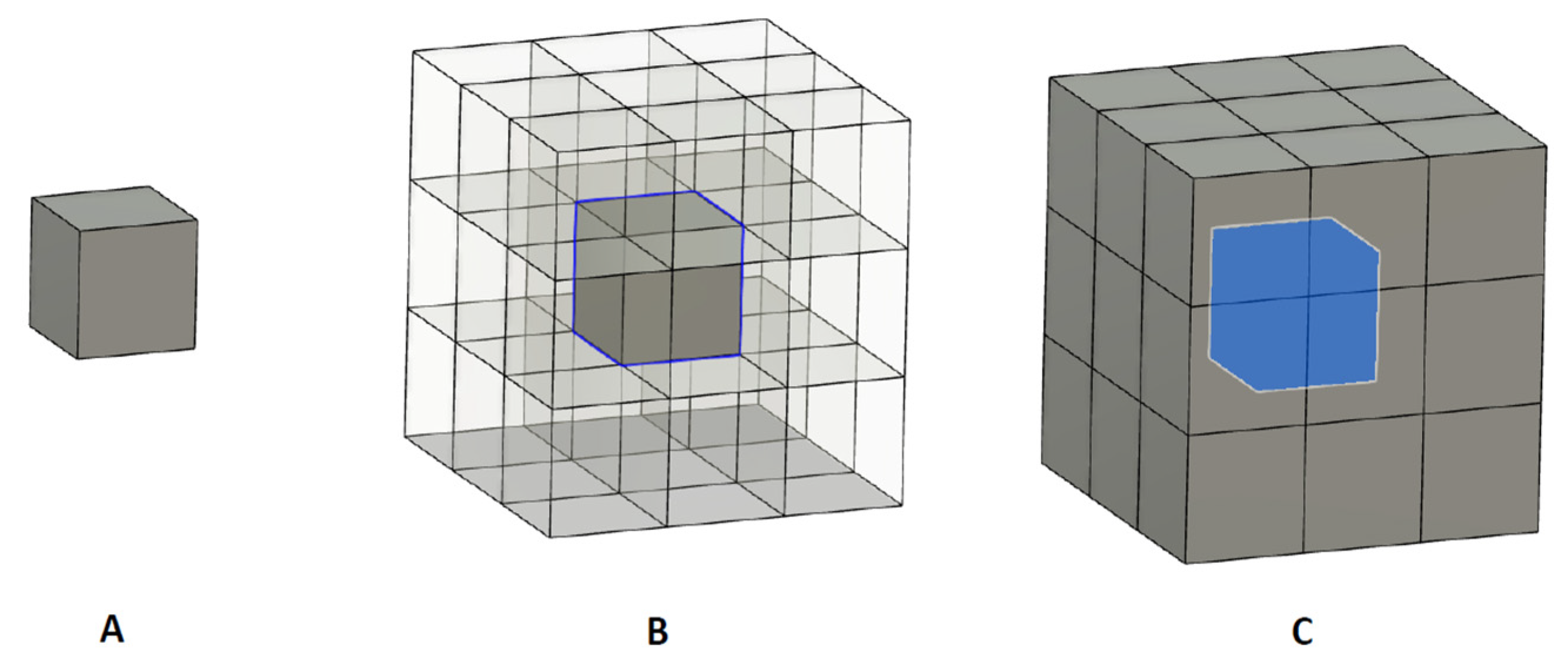
The generation of collision points starts with a dilation operation over the environment point cloud, and applies over the material point cloud, which is implemented in each case using as structuring element cube of 3 × 3 × 3 points. The dilation of the input point cloud by the cube of 3 × 3 × 3 (which corresponds to a cube of 27 points), can be understood as the locus of the points covered by the cube of 3 × 3 × 3 point when the center of it, moves within the input point cloud. The dilation operation is defined as follows:
where
is the initial point cloud, and
is the structuring element (cube 3 × 3 × 3).
This means that for each initial point, 26 extra points are created, which will surround the initial point (27 points in total).
Figure 7 shows the dilation operation, and the result of this operation on a single voxelized point.
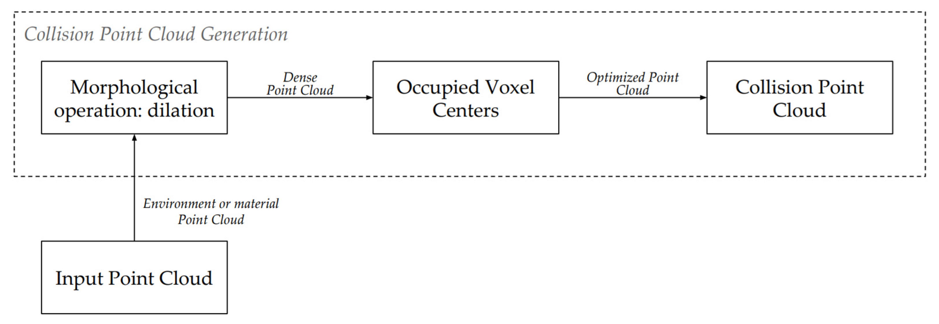
At the end of the morphological dilation, a new point cloud is obtained, with multiple repeated points because the implemented dilation algorithm does not check if there is already a point in the space where the new points are generated. To eliminate this redundant data and to increase the algorithm’s performance, the resulting cloud is voxelized again.
Figure 8 shows the process to obtain the collision points.
As mentioned, the collision point cloud is composed of two parts. The first part will come from the processing of the point cloud belonging to the environment model. As this model is static and was previously calculated in a previous module, it is only processed once to generate the cloud of collision points belonging to the environment. The second part will come from the processing of the point cloud belonging to the material. As this point cloud is dynamic (it is expected to change frequently), the process of obtaining the collision point cloud is performed in each execution cycle. In this case, for performance reasons, the dilatation operation is performed once per cycle.
In the case of requiring to generate a thicker collision point cloud, several dilation iterations should be performed in the same cycle. This would result in a larger safety distance between the real object and end effector.
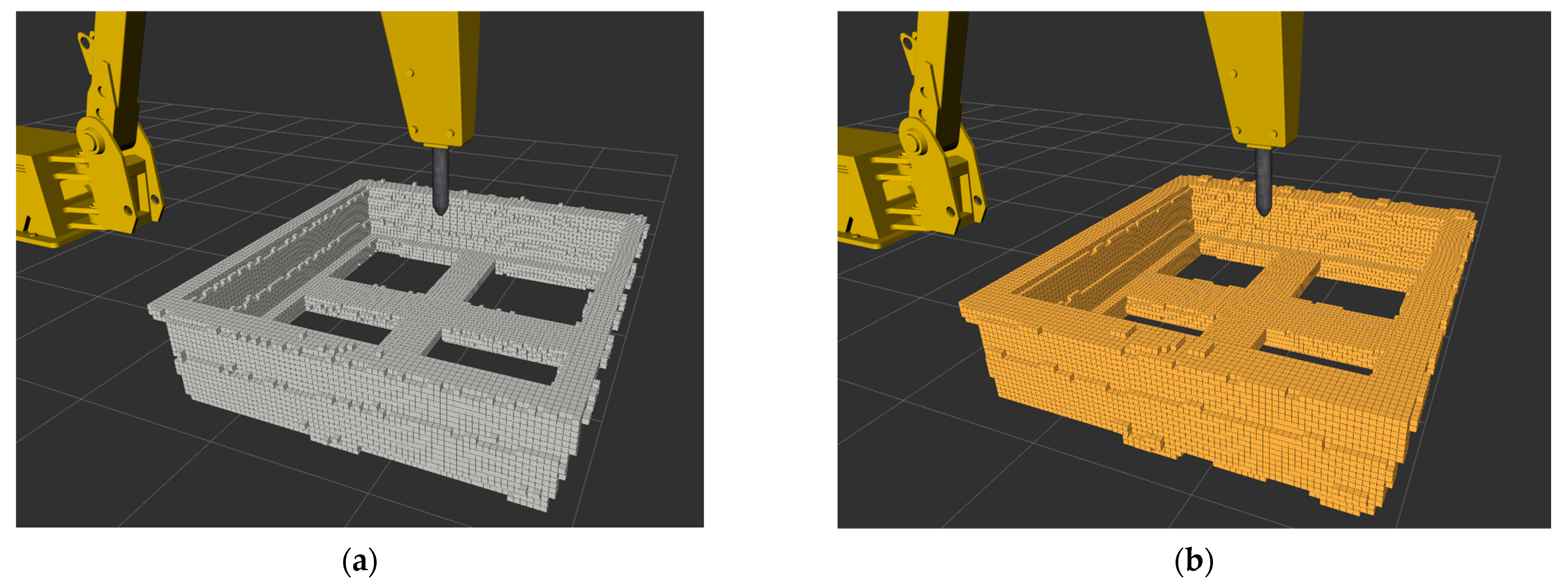
Figure 9 shows a comparison between the point cloud of the generated grizzly model and the point cloud resulting from the dilation process.
Therefore, the resulting collision cloud will be the concatenation of points from the static processing (performed only once at the beginning of the program) of the environment model, with that of the dynamic processing of the material (performed in each cycle). This point cloud will result in a more homogeneous cloud, filling the empty spaces due to the imperfection of the sensors.
It must be emphasized that at any moment, the user can choose using just the environment model for the generation of the collision point cloud, not including the point clouds associated to the material. This is normally made just before placing the hammer on the rock to be broken. The user makes the selection of this operation mode by just pressing a button in the haptic device.
2.5. Haptic Feedback Calculation
This module generates the haptic feedback that will restrict the movement of the joystick axes and the movement of the impact hammer. For this purpose, a so-called virtual collision region is generated around the end effector, which represents the space of the possible future positions of the end-effector, considering the direction in which it moves. The intersection of the virtual collision region with the collision point cloud will indicate possible collisions of the end-effector with the environment.
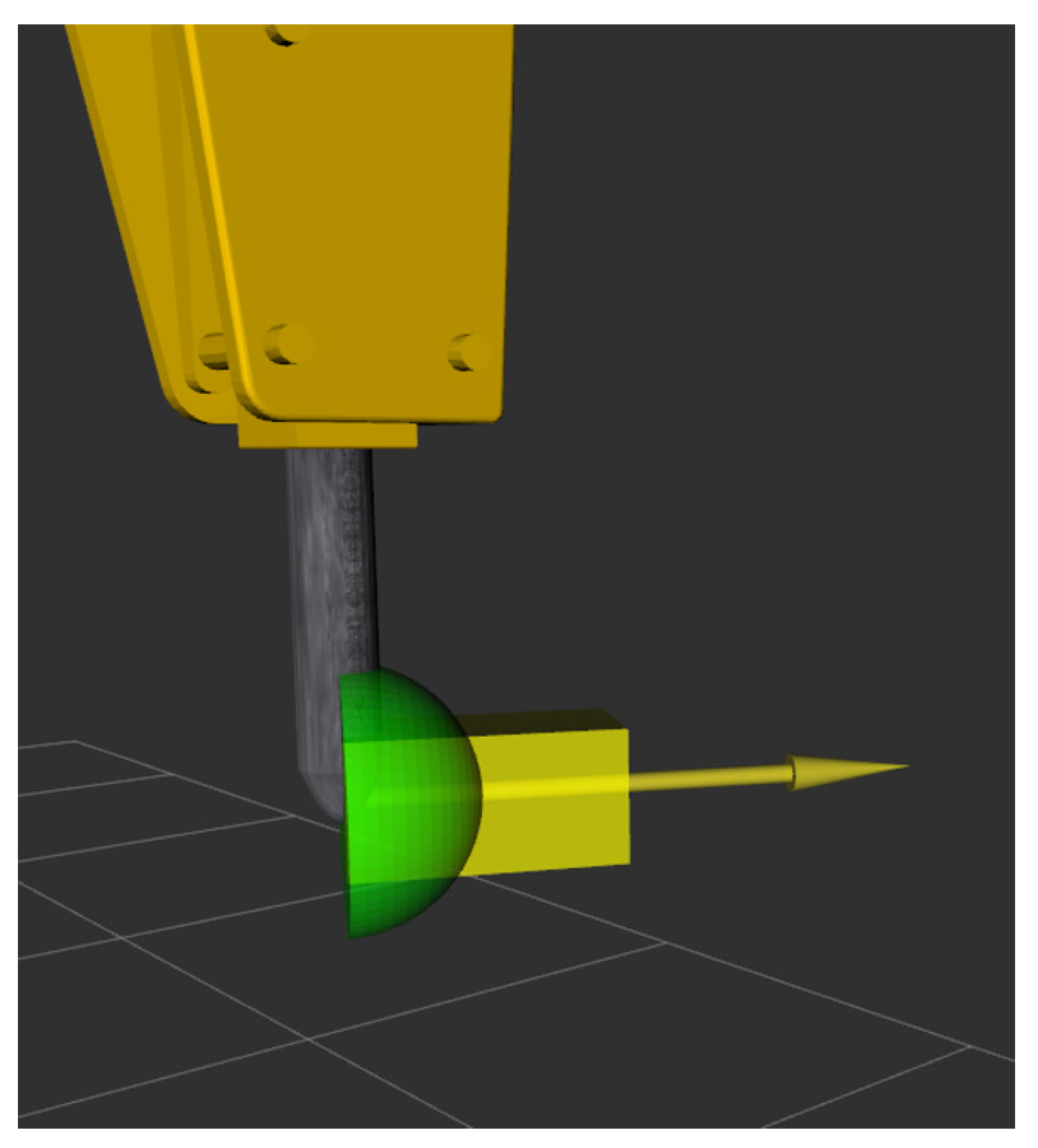
For simplicity, in this work two different geometries are used for representing the virtual collision region: A rectangular cuboid and a semi-sphere, which are positioned at the end-effector point that is located on the tip of the chisel.
Figure 10 shows these geometries, which are oriented with respect to the direction of movement of the end-effector. In this simulation, the yellow arrow corresponds to the direction of motion of the end-effector.
As mentioned, the intersection of the virtual collision region with the collision point cloud will indicate how close is the effector to collide if the current direction and velocity of movement are maintained. The orientation of the virtual collision region has a direct relation to the direction of displacement of the end-effector, and the region it represents indicates the possible future positions in which the effector will find itself in future time steps.
The length of the cuboid is selected as the maximum distance that the effector will move before stopping (inertia of the system). The height and width of the cuboid are slightly larger than the height and width of the end-effector. These values make it possible to distinguish when the end-effector is in an apparent collision state with the collision point clouds, and therefore perform subsequent actions on the effector to avoid the collision. However, it could happen that a sudden movement in the actuation of the controls would produce an abrupt change on the movement direction of the end-effector, resulting in a collision that cannot be detected by the cuboid. To avoid this situation, the semi-sphere region will act as a safety region, detecting these particular cases, where the effector is not in a collision direction, but very close to the objects.
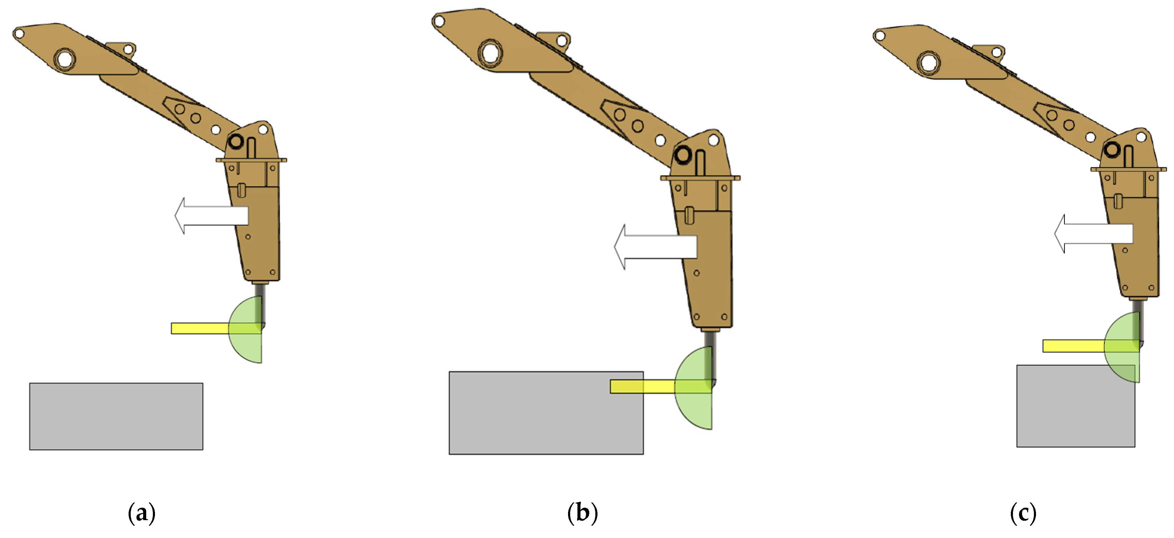
Thus, depending on the positions of the virtual collision region with respect to the collision point cloud, three different cases can be identified:
Rectangular cuboid and semi-sphere regions without intersection with the collision point cloud (see
Figure 11a). In this case the impact hammer can continue its trajectory;
Rectangular cuboid intersects the collision point cloud (see
Figure 11b). In this case, the velocity will be reduced according to the distance to the obstacle (see explanation in next sub section);
Semi-sphere region intersects the collision point cloud and the cuboid does not (see
Figure 11c). In this case the velocity will be reduced to 50% (see explanation in next sub section).
The output of haptic feedback (f) has three values: A Boolean indicating if the cuboid intersects the collision point cloud or not, a Boolean value indicating if the semi-sphere intersects the collision point cloud or not, and a normalized value that indicates a level of safety of executing a command.
The level of safety parameter (
) is calculated using the distance from the end-effector to the collision point cloud (
), as the percentage of the cuboid region lying outside the intersection with the collision point cloud. To calculate this percentage, a max distance (
) is predefined. This distance is considered as a deceleration distance by the end effector when it moves with the maximal allowable speed and it stops. Thus,
is calculated as:
2.6. Haptic Control Interface
This module limits the end-effector’s actuation orders. Depending on the distances between the virtual collision region and collision point cloud, the maximum allowed speed will change, so that the effector does not collide and is not damaged. According to the cases defined in the former sub section:
The use of the square of S is inspired by the fact that the kinetic energy depends on the square of the speed.
Thus, the magnitude of the commands on the end-effector will decrease its maximum allowable speed as it gets closer to the collision point-cloud, arriving with velocity tending to zero as it touches the collision point cloud.
- 3.
Semi-sphere region intersects the collision point cloud and the cuboid does not. In this case the end effector speed is limited to 50% of the maximum speed. In other words, if a higher effector speed is attempted under this condition, the system will automatically limit the speed. In case the effector movement is attempted at a lower speed, the system will not make any adjustment to the speed.
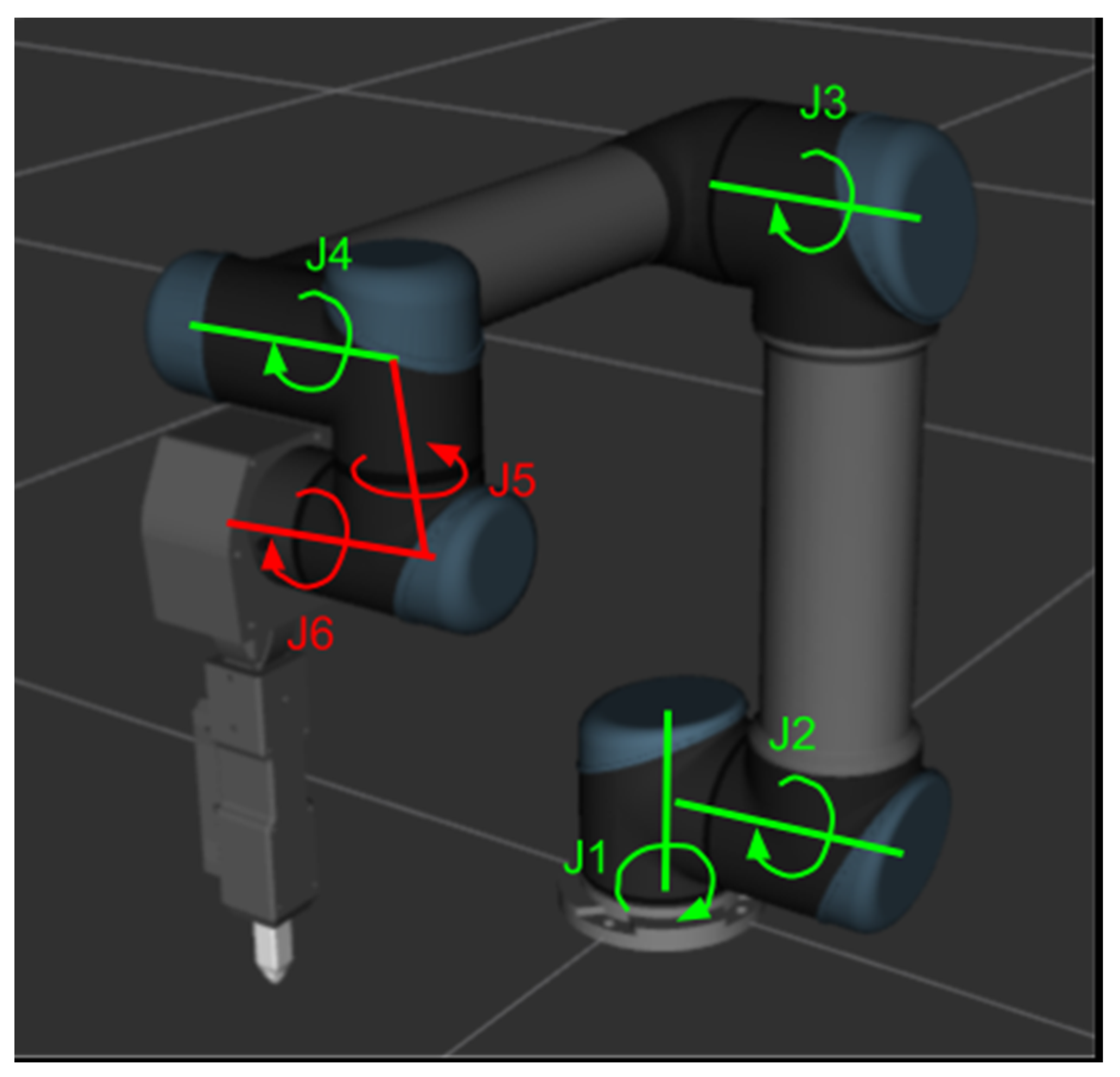
2.7. Inverse Kinematics
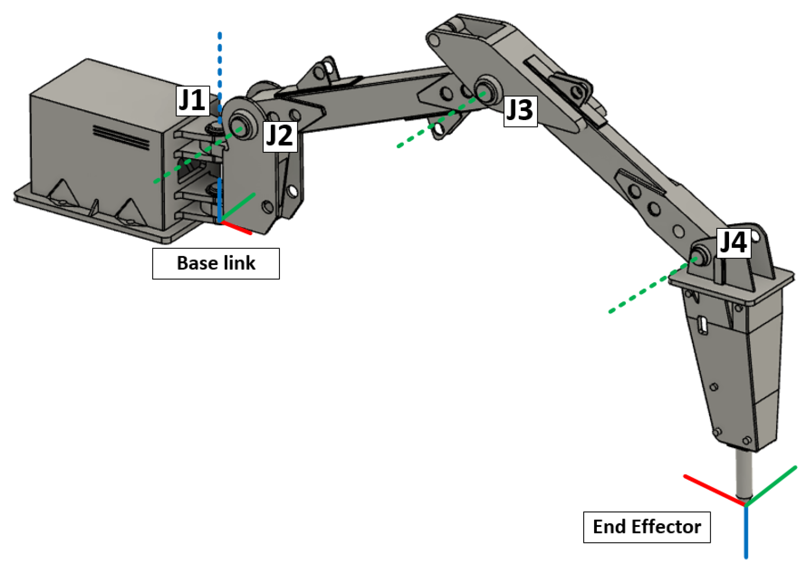
This module adapts desired velocities on the end-effector to the corresponding joint velocities. To do this task, the Jacobian pseudo inverse of the kinematic model is calculated using the current state of the machine to perform this conversion as:
where
corresponds to a vector with the velocities on some axis of the Cartesian space, {x, y, z, pitch} in this case;
corresponds to the speed on each articulation on the machine {q0, q1, q2, q3} related to its respective joint, and
corresponds to the pseudo-inverse of the Jacobian of the kinematic model of the arm, which is shown in
Figure 12.
The pseudo inverse method is implemented to reduce the dimension of the Jacobian, which is originally declared in Cartesian space {x, y, z, roll, pitch, and yaw}. The kinematic model of impact hammer is generated by a kinematic tool (moveit) and allows for simplifying the number of the states on the Cartesian space to {x, y, z, pith}.
2.8. Haptic Controller
The haptic control has the task of alerting the user of possible collisions using the haptic device. The form of warning that has been implemented is to restrict the range of movement of haptic device (control axes). In this way, as the effector gets closer to collision, the restriction to the movement of the axes will be greater, exerting a counter force to the user if they want to pass the calculated limits.
Therefore, the restriction of movements to the axes of the haptic device will allow on the one hand to alert the user of possible collisions (and how close the hammer is to collision), and on the other hand, it will be able to slow down the hammer by limiting the possible movement actions.
In the same way as the haptic control interface, the limitation sent to the haptic controller depends on three states of haptic operation:
Rectangular cuboid and semi-sphere regions without intersection with the collision point cloud: The haptic control does not exert any counteracting force to the operator’s actuation. In this case, the user will not feel any restriction on the movement of any of the control axes;
- 4.
Rectangular cuboid intersects the collision point cloud: In this case the movement of each axis is limited, depending on the remaining distance to the object to collide. The axel movement limitation is:
Thus, as the effector approaches the object to collide (distance in range {0,1}), the control will limit the movement of its axes, opposing the user’s action. In case the user operates under the calculated limit, he/she will not feel the movement limitations of the control.
- 5.
Semi-sphere region intersects the collision point cloud and the cuboid does not. When this condition is activated, the movement is limited to 50%, which means that the operator will feel that the control only allows them to move the axes, normally the first half in each axis. When trying to exceed the second half, the haptic control will exert a repulsive force opposite to the operator’s direction.
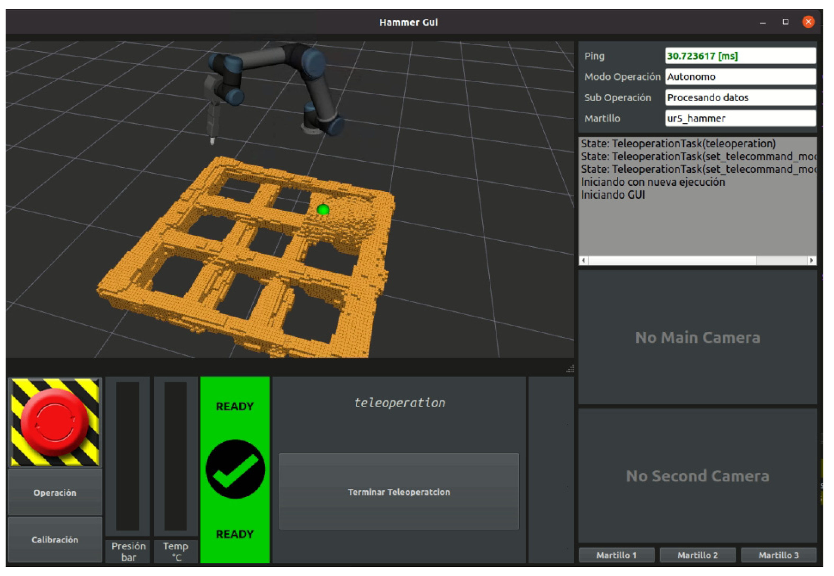
2.9. User Interface
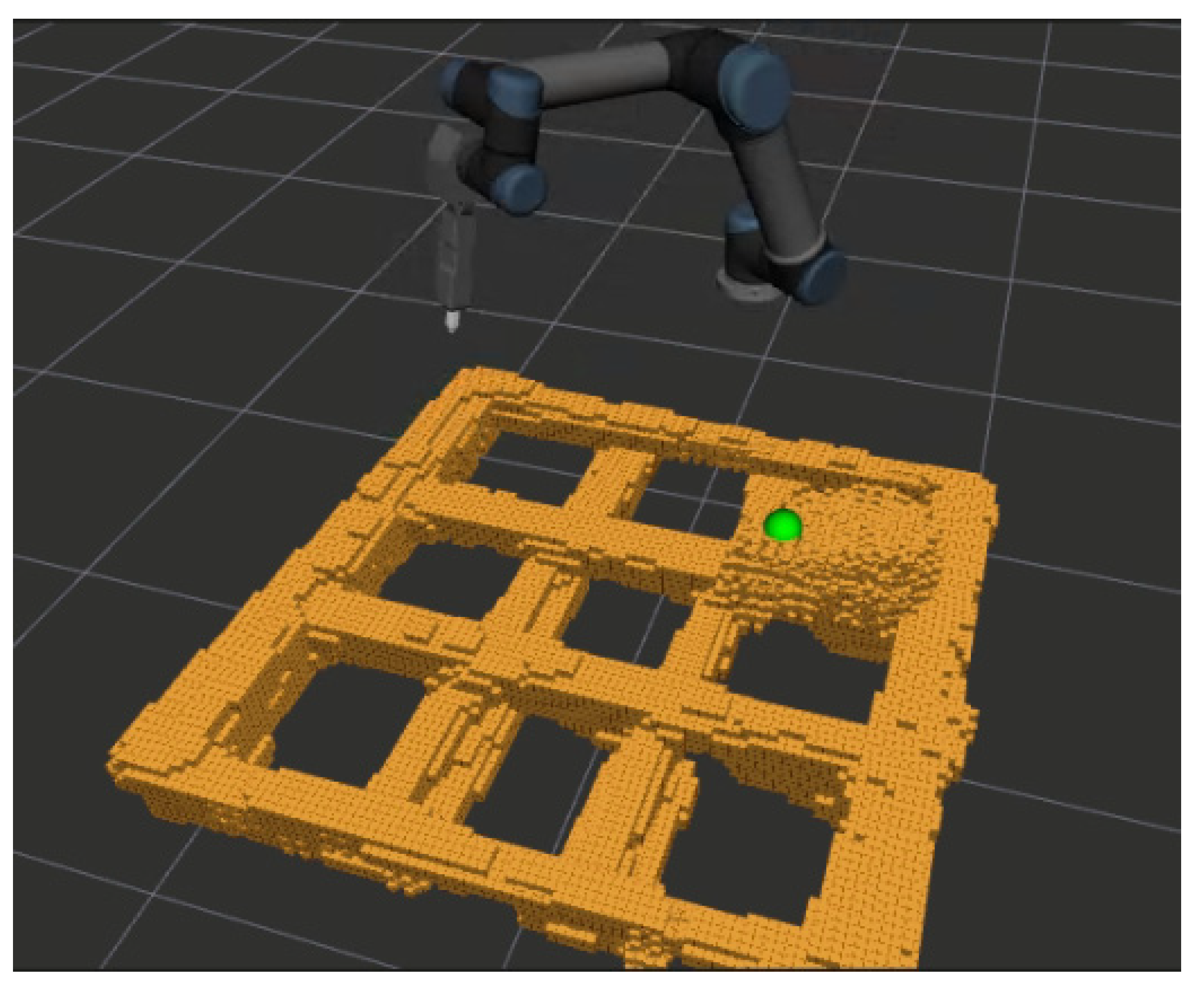
The user interface is used to provide the operator with multiple perspectives of the grid material. Here the operator can move the point cloud presented to him, and adjust the view to their liking, in order to improve the perception of the objects within the hammer workspace. The visual output of this interface is in the form of a visualization of the point clouds, previously processed by the modules described above.
Figure 13 shows the interface implemented in this project. The interface shows the model of the UR5 robot, which can be rotated as desired by the user of the interface, and the cloud of collision points (in yellow). This interface includes visual signals to inform the operator of the current operation conditions.
4. Discussion
The reported experiments show that the developed haptic tele-operation system allows for improving the tele-operation experience of the user. The processing of the different point clouds acquired using 3D LIDARs manages to correctly separate the rocks from the grizzly. The haptic controller and control interface manage to provide enough force feedback to the operator to get their attention, so that they can perceive elements close to the end-effector, thus increasing the perception of the environment in the operating area. In addition, the user interface improves the visual perception of the elements, improving the control over the robot, even if the haptic feedback part is not used.
The results depicted in
Table 2 allow for comparing the different configurations, and in this way the different features that the proposed haptic tele-operation system includes.
When comparing configurations, A and B, a significant improvement of the performance of the task is observed when the end-effector controller is used (configuration B). The main reason for this, is that controlling an arm by actuating directly the joints is a difficult task that requires much preparation and practice. This way, controlling the end-effector makes the operation more affordable for new users.
When comparing configurations B and C, it can be observed a slight improvement in the case of using a 3D model of the environment (configuration C). The reason for this is that in case B, the operator cannot change the perspective, and therefore, in some cases it is not possible to have a proper visualization to avoid colliding. When the operator uses configuration C, they have the possibility of changing the viewpoint and in this way avoid collisions.
Finally, when comparing configurations C and D, a more notorious performance improvement is detected in the case of using haptic feedback. The reason for that is that the operator does not have to worry about colliding with the environment or rocks. This produces that the operator is able to increase the speed, and can move the arm without worrying about collisions.
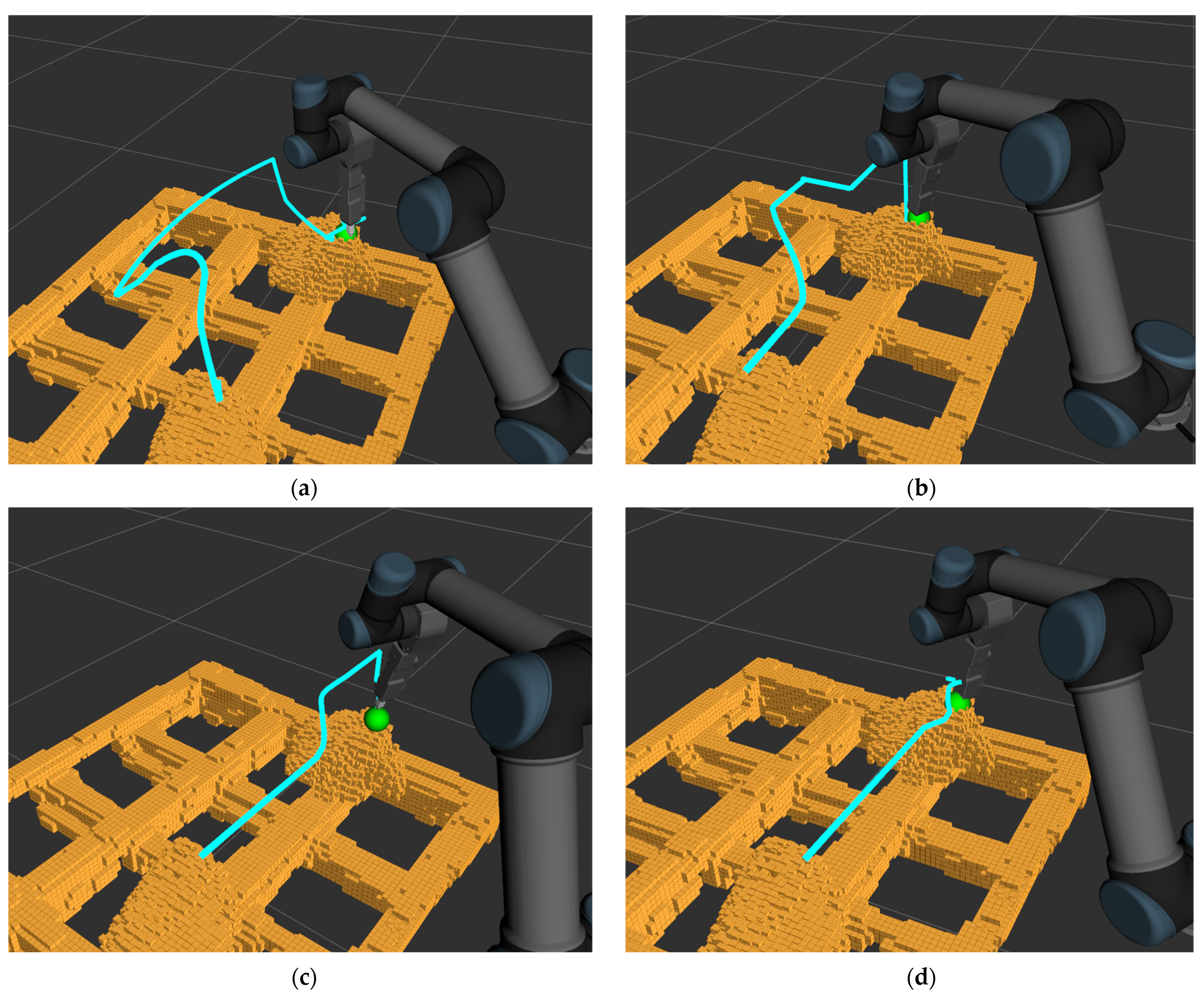
By comparing the different configurations using the hammer tip trajectories (see
Figure 19), it is possible to visualize the effect of each configuration on the end effector path. In this aspect, configuration A and B generate a larger deviation when approaching the target, due to the poor perspective that make it more comfortable to first raise the end-effector and then approaching the target from a higher position in order to get a better perspective. In contrast, configurations C and D generate a path that approach the end-effector directly to the target, as they are able to manage the perspective, but then finish with different maneuvers of positioning. In particular, configuration D presents a slight rise over the rock when approaching as a result of haptic feedback that allow the operator to perform fine maneuvers more easily, unlike configuration C which tends to perform wider maneuvers at the final stage of the positioning process.
Similar to [
9,
10,
11], the results show that using a haptic system improves the performance and safety of performing a certain task using a robot manipulator. In addition to analyzing the number of collisions, our study evaluates the level of precision of the task being executed, and this type of consideration is not studied in other works and it is relevant for the context of this type of task in particular, which is positioning the chisel for breaking rock. In addition, our system uses the virtual environment to generate multi-perceptive views to aid in performing a task. This feature is not analyzed in the other studies describing haptic tele-operation based on point-clouds [
9,
10,
11].
It should also be noted that although the development is intended for industrial environments with a real impact hammer, a small-scale robotic arm was used for the laboratory tests, which implies different behaviors due to the different construction of these elements (electric vs. hydraulic). This may imply that for final implementation, major adjustments may be needed for the control and haptic feedback modules of the system.
5. Conclusions
This paper addressed the haptic tele-operation of impact hammers. The proposed haptic tele-operation system is based on a 3D model of the environment, which is used to estimate repulsion forces that are transferred to the operator via a haptic device, so that the hammer does not collide with the structures of the mine. The system also allows for identifying the oversized boulders deposited on the grizzly, notifying the operator every time the orepass is blocked, as well as providing them with different 3D views of the environment.
A proof of concept was presented using a scaled setup. The reported experiments show that the use of a 3D model of the environment and the use of haptic feedback improves the tele-operation experience. When using the proposed system, operators were able to increase the success rate of the tele-operation task, and at the same time to reduce the completion time and the length of the path that the end-effector must follow.
As part of our future work, we will validate the tele-operation system using a real impact hammer operating in a real production environment of an underground mine. In that environment, it is expected that several aspects of the operation will emerge which are not reproducible or were not considered in our laboratory environment. The analysis of these new experiments allows for improving and adapting the haptic feedback algorithm to be applied in production systems. In addition, the system will be validated with expert rock breaker operators in order to be able to quantify the real operational impact of its use. Given that a professional operator has a higher level of expertise in controlling the hammer with the current limitations of traditional systems, the performance improvement could be different in relation to a non-expert operator.
Further improvement will focus on the use of haptic feedback to develop assistive tele-operation to guide the operator to follow optimal trajectories. Assistive tele-operation requires defining hammer tip trajectories for successful positioning and providing haptic feedback when the operator uses commands that move the hammer tip away from these trajectories.


