Article

Development and Experimental Assessment of a Model for the Material Deposition by Laser-Induced Forward Transfer

1
Department of Biomolecular Systems, Max Planck Institute of Colloids and Interfaces, Am Muehlenberg 1, 14476 Potsdam, Germany
2
Department of System Dynamics and Friction Physics, Institute of Mechanics, Technical University of Berlin, Strasse des 17. Juni 135, 10623 Berlin, Germany
3
Berlin School for Library and Information Science, Humboldt University of Berlin, Unter den Linden 6, 10117 Berlin, Germany
4
Institute of Microstructure Technology, Karlsruhe Institute of Technology, Hermann-von-Helmholtz-Platz 1, 76344 Eggenstein-Leopoldshafen, Germany
*
Author to whom correspondence should be addressed.
Appl. Sci. 2022, 12(3), 1361; https://doi.org/10.3390/app12031361
Submission received: 14 December 2021 / Revised: 24 January 2022 / Accepted: 25 January 2022 / Published: 27 January 2022
(This article belongs to the Section Applied Physics General)

Abstract

:
The potential to deposit minute amounts of material from a donor to an acceptor substrate at precise locations makes laser-induced forward transfer (LIFT) a frequently used tool within different research fields, such as materials science and biotechnology. While many different types of LIFT exist, each specialized LIFT application is based on a different underlying transfer mechanism, which affects the to-be-transferred materials in different ways. Thus, a characterization of these mechanisms is necessary to understand their limitations. The most common investigative methods are high-speed imaging and numerical modeling. However, neither of these can, to date, quantify the material deposition. Here, analytical solutions are derived for the contact-based material deposition by LIFT, which are based on a previously observed equilibrium state. Moreover, an analytical solution for the previously unrecognized ejection-based material deposition is proposed, which is detectable by introducing a distance between the donor and acceptor substrates. This secondary mechanism is particularly relevant in large scale production, since each deposition from a donor substrate potentially induces a local distance between the donor and acceptor substrates.

1. Introduction

One of the earliest reports of a laser-induced material deposition demonstrated the transfer of ink from a substrate toward a recording medium [1]. Following this discovery, 15 years passed until Bohandy et al. introduced the term laser-induced forward transfer (LIFT) to describe the deposition of copper and silver from a donor to an acceptor substrate [2,3]. Currently, the term LIFT is used to describe any process in which material is transferred from a donor to an acceptor substrate through laser irradiation (in the lasing direction). Moreover, due to the precision of laser-based systems and the potential to deposit minute amounts of material, as well as the increased access to commercial laser systems, LIFT processes have influenced a variety of research fields. Particularly, the potential use and transfer behavior of metals [4,5,6,7,8], polymers [9], and liquids [10,11,12,13,14] have been well studied.
An interesting approach to transfer delicate materials is the dynamic release layer, LIFT [15]. This process utilizes a sacrificial intermediate layer as an absorbent to protect the donor substrate from the laser irradiation. For example, the compatibility of highly absorbing (penetration depth < layer thickness) sacrificial metal layers [16,17] with biomolecules enables the deposition of such materials [18,19], since the transfer is driven by melting and/or vaporization of the metal layer. However, the ablation of the metal layer potentially contaminates the transferred material. To avoid such contamination, sacrificial polymer layers were introduced. Two of the most common approaches are evaporation and ejection of triazene polymer (TP) [20] and blister-actuated (BA) [21] LIFT, which is based on the thermal polyimide expansion. On the one hand, the customizable absorption spectrum of the triazene polymer and potential to transfer solid and liquid materials through TP LIFT make it a versatile tool for the generation of polymer sensors [22] and organic light emitting diodes [23]. However, TP LIFT is an ablation-based process [24,25]. Thus, the ablation can still harm extremely delicate materials, and the irradiated donor substrate location can only be used once. On the other hand, only liquid materials can be transferred through the BA LIFT, and the thick isolating polyimide layer has usually a set absorption spectrum. Nevertheless, the isolating polyimide effectively mitigates the interaction between the laser and to-be-transferred material, which enables the manufacturing of light-emitting diodes and biosensors [26,27]. Since the material deposition is based on a contact between the acceptor substrate and a blister-induced directional jet of the donor substrate [28], the irradiated location is reusable.
In 2016, the combinatorial LIFT (cLIFT) [29] was introduced for parallel and on-demand chemical synthesis [30]. Within this process, a thick reusable polyimide layer is used as a sacrificial layer, and a polymer coating embedded with chemical building blocks is used as the donor substrate. We previously showed that the material deposition through cLIFT is mainly driven by the expansion of the sacrificial polyimide layer during laser irradiation and can be divided into four steps (Figure 1): (a) minor deformation of the polyimide after initial laser irradiation; (b) bell-shaped expansion of the polyimide in normal direction of the surface at a given time with a continuously decreasing expansion rate; (c) established stable contact with the acceptor due to the expanded polyimide with no further polyimide expansion; (d) relaxation of the polyimide layer and donor substrate material deposition after finished laser irradiation.
Despite some similarities with the BA LIFT, the material deposition mainly occurs through a direct contact between the donor and acceptor substrates, which is established by the expansion of the polyimide layer [31]. Yet, a ring structure appears with a large distance (distance > polyimide expansion) between the donor and acceptor substrates [31], which indicates an additional ejection-based material deposition, radially to the expanding surface. A similar phenomenon was also reported for the BA LIFT [32].
Here, we build upon the reported transfer behavior within the cLIFT and derive analytical solutions to characterize the sacrificial polyimide layer expansion and material deposition (volume and width) through the contact- and potentially ejection-based transfer mechanisms. These derivations are quantitatively (contact-based) or qualitatively (ejection-based) validated against fluorescence imaging, vertical scanning interferometry, and/or high-speed imaging measurements.

2. Materials and Methods

2.1. Lasing Setup

The lasing setup is part of an automated synthesizer, which was previously reported [33]. It contains a 405 n m wavelength diode laser (iBeam smart 405-S, TOPTICA Photonics AG, Munich, Germany) that has a Gaussian beam profile and a maximum power of 300 m W , which is only used in the continuous wave regime (> 10 6 s). Within the setup, the laser is directed by two mirrors into a laser scanning system (intelliSCAN III 10, SCANLAB GmbH, Puchheim, Germany) equipped with an F-Theta-lens (JENar 170-355-140, JENOPTIK Optical Systems GmbH, Jena, Germany) that has a focal plane of 170 m m . After the laser beam exits the F-Theta-lens, the measured maximum laser power is 210 m W . Moreover, a positioning table attached to the z-stage is used to move the surface of the acceptor substrate into the focus plane. The focus plane is determined through a camera/microscope unit (i.e., finding the most intense and smallest laser spot), which is attached to the z-stage. To perform the material deposition, a donor substrate is placed on top of the acceptor substrate, and the laser is initiated by a commercial laser software (laserDESK version 1.4.3.1, SCANLAB GmbH).

2.2. Donor Substrate Preparation

For the preparation of a donor substrate, self-adhesive polyimide (Kapton HN, DuPont, CMC Klebetechnik GmbH, Frankenthal, Germany) is attached to a microscope glass slide, and a previously prepared solution is spin-coated on top. Particularly, for a Rhodamine 150 donor substrate, 150 m g styrene acrylic copolymer (SLEC LT 7552, Sekisui Chemical, Tokyo, Japan) is dissolved in 900 μ L dichloromethane (DCM), mixed with 100 μ L N,N-dimethylformamide (DMF) containing 10 μ g mL−1 Rhodamine 6G (Chemodex Ltd., St. Gallen, Switzerland), and spin-coated with 80 rounds per second.

2.3. Fluorescence Imaging

Fluorescence images were evaluated with the fluorescence scanner Genepix 4000B (Molecular Devices, San Jose, CA, USA) with a 5 μ m resolution, 33% laser power, and a photo multiplier gain of 600 at 532 n m wavelength. In the following, fluorescence imaging is abbreviated by Fluo.

2.4. Vertical Scanning Interferometry

Vertical scanning interferometry measurements were evaluated with a smartWLI compact (Gesellschaft für Bild- und Signalverarbeitung (GBS) GmbH, Ilmenau, Germany) with a 5× magnification lens. In the following, vertical scanning interferometry is abbreviated by VSI.

2.5. High-Speed Imaging

High-speed imaging measurements were carried out with a PHANTOM V210 (Vision Research, Wayne, NJ, USA) high-speed camera equipped with a 10× magnification lens. For all experiments, a constant field of view of 304 × 128 pixels (spatial resolution: 1 pixel = 2.2   μ m ) was chosen to capture the surface expansion regardless of the lasing parameters. All experiments were performed with a frame rate of 39 . 000 fps (time resolution: 1 frame = 2.56 · 10 5 s). The high-speed imaging data and a full description of the setup was previously reported [31].

2.6. Spot Evaluation

Deposited material spots were automatically detected through a developed spot detection program [34], which has a maximum error of ± 4 pixel. The software was developed in Python (see Supplementary Materials).

3. Results and Discussion

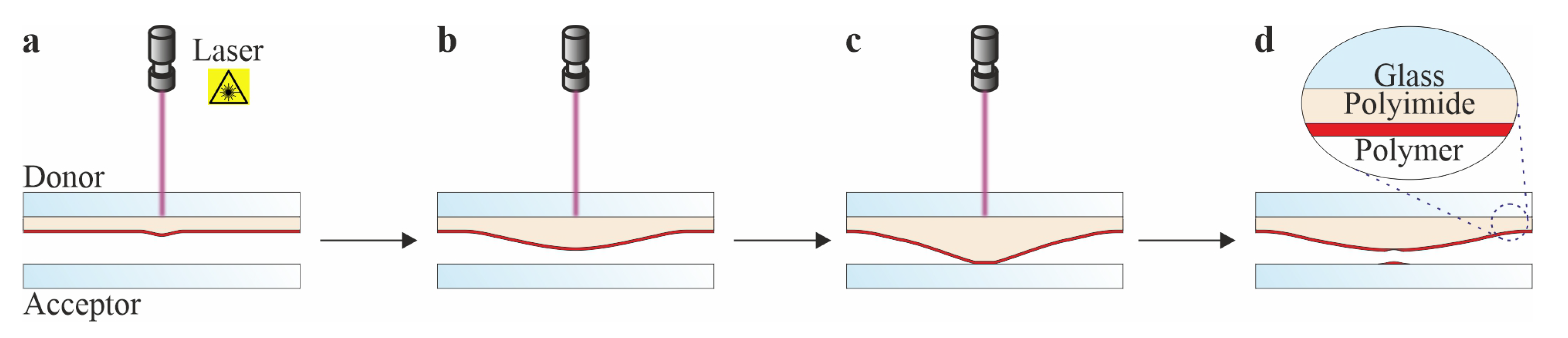
3.1. Contact-Based Transfer Mechanism

Since the polyimide is the main driver of the contact-based material deposition within the cLIFT, a characterization of the observed expansion behavior has to be proposed to predict the material deposition (e.g., deposited spot volume V T and width d T ). In addition to the process separation (Figure 1), we further observed that the polyimide expansion rate decreases under continuous laser irradiation until a maximum and stable blister/structure is reached. Consequently, the occurring structure implies that the polyimide accumulates energy over time E ( t ) (stored energy) until a final equilibrium is reached that cannot be surpassed (Equation (1)). This behavior strongly resembles the mechanistic analogue of a charging capacitor. For simplicity, the equilibrium energy is only considered to depend on the laser irradiance and lasing duration. Other potential influencing parameters, such as heat transfer and thermal expansion of the polyimide, are not explicitly characterized, since they should implicitly influence the accumulation of stored energy. Furthermore, the distance between irradiated locations is experimentally determined to be large enough to neglect the effect of residual heat.
E ( t t eq ) = E eq
The stored energy at t + t ˜ is approximated up to the first order by Equation (2), which leads to Equation (3) after evaluating t ˜ at t eq . Within this equation, a material (polyimide) dependent parameter k is introduced, which specifies the ability of the material to accumulate energy per unit time. This parameter indicates the proportion of storable energy E eq E ( t ) that the material can accumulate over a distinct time frame (i.e., increase in stored energy E ( t ) over time). This captures the observed effect of continuously decreasing polyimide expansion toward the maximum achievable expansion. Utilizing the initial temporal boundary condition E ( t = 0 ) = 0 , which captures the initial zero-expansion, Equation (3) can be solved to obtain Equation (4) for the progression of the stored energy. Thus, the expansion of the polyimide can be described by the (inverse of the) exponential decay function.
E ( t + t ˜ ) = E ( t ) + d E ( t ) d t t ˜
d E ( t ) d t = k ( E eq E ( t ) ) with k R
E ( t ) = E eq ( 1 e k t )
The expansion of the polyimide volume V P is a result of the mechanical work induced by this stored energy ( E ( t ) V P ( t ) ). Furthermore, as an increasing polyimide expansion (increasing V P ) induces an increasing material deposition, the expanded and transferred volumes can be assumed to be proportional V P ( t ) V T ( t ) to each other (neglecting higher order and non-linear terms, such as donor coating thickness, phase change, and gas expansion). To obtain a relationship for the spot width d T , which is another observable quantity of interest, the deposited bell-shaped volume over a circular area A T , c is approximated by a characteristic height h T , c . For simplicity, the deposition is assumed to expand isotropically, and therefore, the characteristic height relates to the spot width via a constant, which yields Equations (5)–(7).
V T ( t ) A T , c h T , c V T ( t ) d T 3 with A T , c π 4 d T 2 and h T , c d T
V T ( t ) = α E eq ( 1 e k t ) with α R
d T ( t ) = β ( E eq ) 1 3 ( 1 e k t ) 1 3 with β R
Next to the polyimide expansion, a proportionality between the laser beam diameter and maximum contact area was observed [31], which is represented by Equations (8) and (9), assuming a circular contact and deposition area. Following this observation, the focused Gaussian laser beam intensity distribution with radial coordinate r, total power P, set power P i , and focused beam radius ω (≈25 μ m FWHM ⇒ ≈ 42.5   μ m 1 / e 2 ; Figure S1) can be used to define the intensity threshold of the beam radius with the lowest laser power Equation (10). Through this definition, the change of the beam diameter with an increasing laser power can be captured by Equation (11).
d B e a m 3 V T , m a x = lim t V T ( t ) = α E eq
d B e a m d T , m a x = lim t d T ( t ) = β ( E eq ) 1 3
I ( r , P ) = 2 P π ω 2 e 2 r ω 2 I ( r = ω , P = P min ) = 2 P min π ω 2 e 2
I ( r = R , P = P i ) = 2 P i π ω 2 e 2 R ω 2 = ! 2 P min π ω 2 e 2 d B e a m = ω 2 1 + ln P i P min
By now, only an optimal deposition procedure was considered. To account for (weak) lasing parameters without material deposition, constant lower boundary values V T , min and d T , min are introduced, which express the required minimal stored energy for a material deposition. Finally, through the laser power dependent limit and constant threshold values, the deposited spot volume and width can be stated by Equations (12) and (13). These contain two fitting parameters (for the spot volume and width respectively) and the unknown material dependent constant. For completeness, the maximum (or characteristic) surface expansion h P is also determined Equation (14).
V T ( t ) = α ¯ ω 2 1 + ln P i P min 3 ( 1 e k t ) V T , min with α ¯ , V T , min R
d T ( t ) = β ¯ ω 2 1 + ln P i P min ( 1 e k t ) 1 3 d T , min with β ¯ , d T , min R
h P ( t ) = γ ¯ ω 2 1 + ln P i P min ( 1 e k t ) 1 3 h P , min with γ ¯ , h P , min R
To validate the expressions, a parameter variation in lasing power and duration of a Rhodamine 150 donor substrate material deposition (spot width d T ( t ) and volume V T ( t ) ) was measured via fluorescence imaging (Fluo) and vertical scanning interferometry (VSI). Additionally, the previously published high-speed imaging measurements [31] of the maximum polyimide expansion were used to validated the expression h P . These measurements show a good agreement (low root-mean-square deviation) with the predicted trend based on lasing power and duration (Figure 2 and Table S1). Furthermore, the material dependent parameter k varies by ≈13.6 % and ≈39.3 % between the VSI spot width ( d T VSI) and volume ( V T VSI) and fluorescence spot width Fluo ( d T Fluo) respectively (Table S1). This minor variation is contrasted by the larger Fluo and VSI spot width measurements (Figure 2a,b), which can be ascribed to the different detection limits of Fluo and VSI (subnanometer vs. nanometer). Thus, Fluo is preferred to precisely detect minimal amounts of material deposition. Finally, a deviation from the model is observed for the spot width and volume with low lasing power and short lasing durations, as well as high lasing power and long lasing durations for the spot volume. For example, the spot volume deposition with 110 mW lasing power and below 12 ms lasing duration, as well as 210 mW lasing power and above 15 ms lasing duration is mispredicted. The misprediction can be ascribed to the simple constant as a minimal threshold value (e.g., V T , min ) and the neglect of the plastic polyimide expansion.

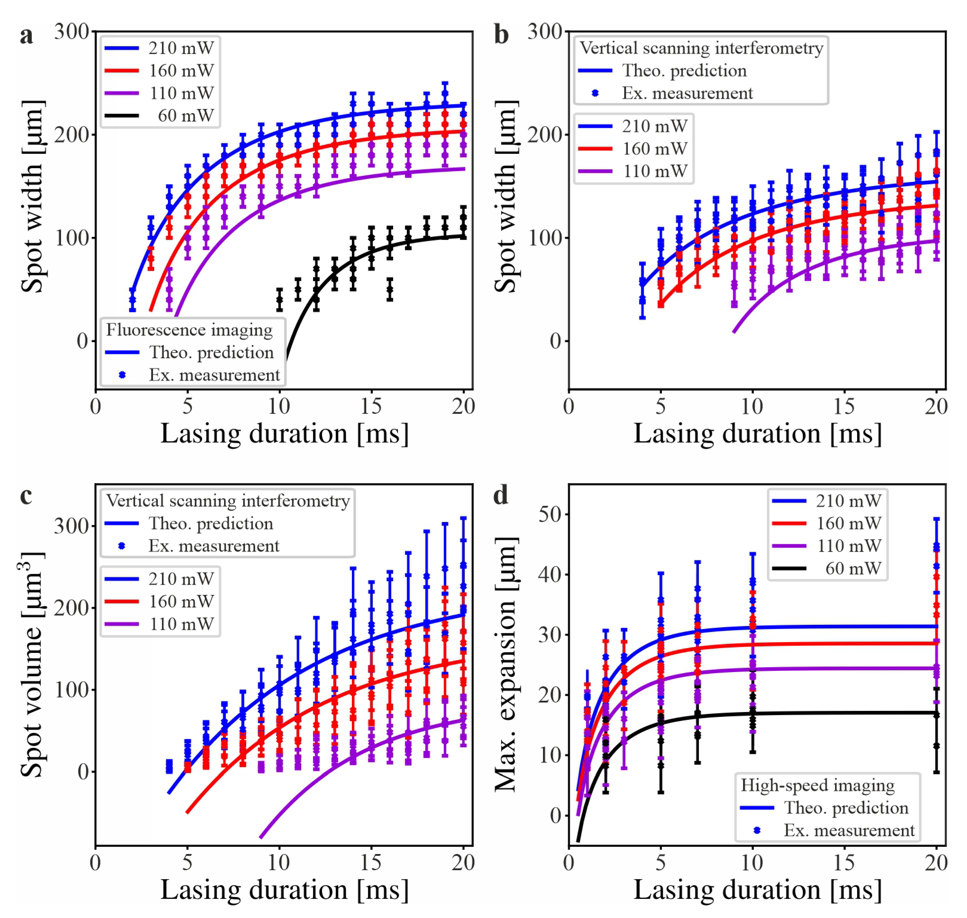
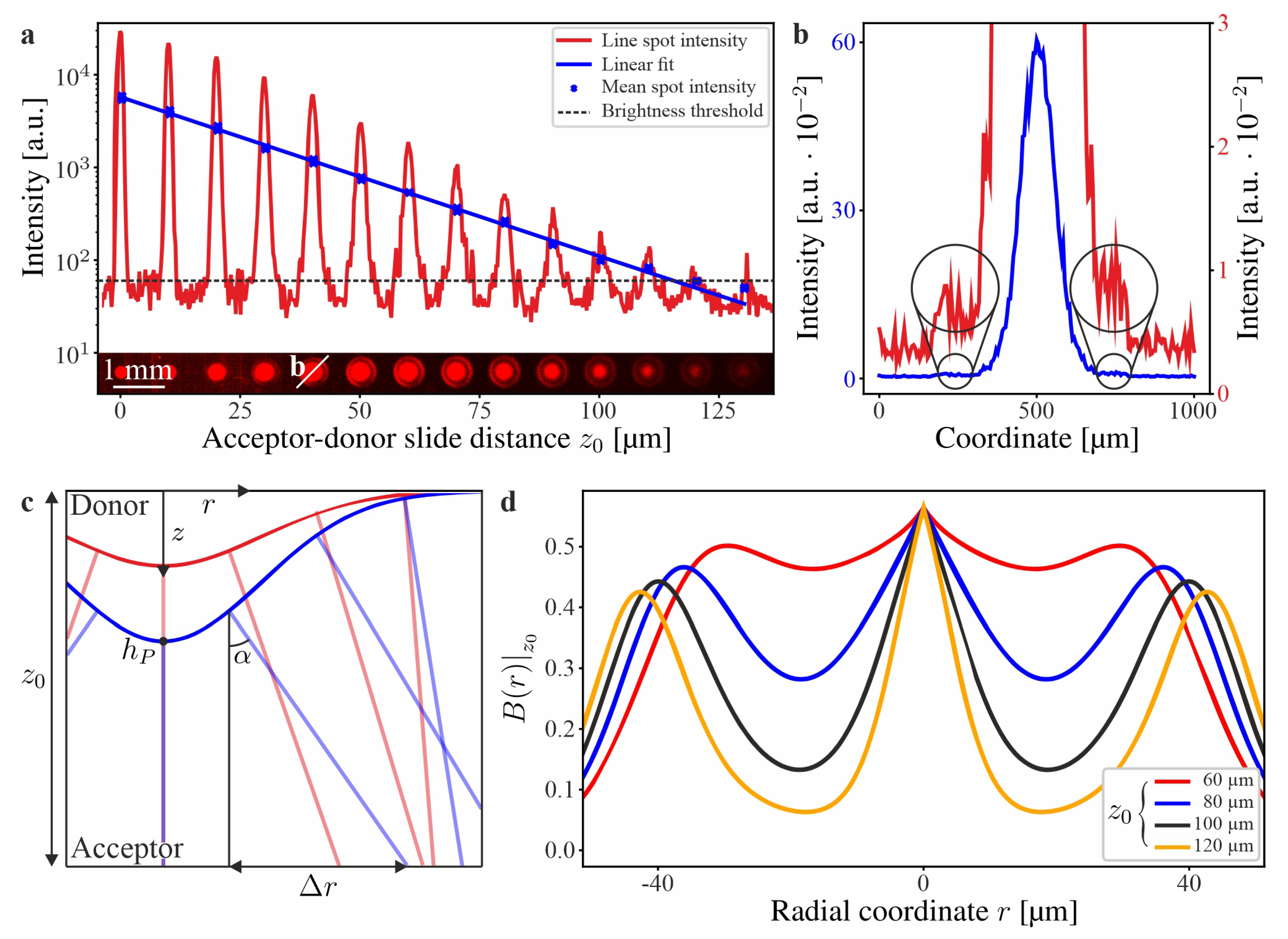
3.2. Ejection-Based Transfer Mechanism

The phenomenon of a ring structure through an artificially introduced gap between the acceptor and donor substrate was previously reported by us [31]. It was not explicitly stated that the material deposition occurs for acceptor–donor substrate distances beyond the maximum polyimide expansion. However, this secondary transfer mechanism is particularly relevant for large scale material deposition, since the non-zero expansion of the polyimide after relaxation induces local distances between the donor and acceptor substrates.
To solely investigate the effect of different acceptor–donor substrate distances, a spacer (200 μ m thickness) was attached on one side of an acceptor substrate (Figure S3) and constant lasing parameters were used (160 mW and 10 ms). This setup enabled the simultaneous investigation of an acceptor–donor substrate distance, ranging from 0 μ m to 200 μ m . The minute amount of deposited material made it impossible to detect the material deposition precisely through VSI. Thus, only Fluo measurements could be analyzed. Not only was an exponential decrease in the mean and line spot intensity observed (Figure 3a), but the occurrence of a ≈1.5–2 orders of magnitude weaker ring structure was detected (Figure 3b). This ring structure surrounds and increases its radius from the main spot deposition with an increasing distance between the acceptor and donor substrates until the main spot deposition vanishes. It is evident that a secondary transfer mechanism exists.
The material deposition occurs for acceptor–donor substrate distances above 40 μ m (maximum polyimide surface expansion of the used lasing parameters; Figure 2). Therefore, the secondary effect is most likely ejection based. Additionally, the polyimide expansion in the normal direction of its own surface (at a given time) implies that the laser-induced temperature gradient acts as a force into that direction. With this constraint, it can be assumed that in the first order, the material ejection is in the normal direction of the polyimide expansion, which is similar to the secondary effect of the blister-actuated LIFT [32]. Based on this assumption, the transformation θ ( r , t ) can be stated Equation (15), which maps the ejection from the donor onto the acceptor substrate (Figure 3c).
θ ( r , t ) z 0 = r + Δ r ( r , t ) z 0 = r + ( z 0 z ( r , t ) ) tan ( α ( r , t ) ) with z 0 z ( r , t )
To analyze the secondary order effect and no superposition with the contact-based material deposition, the distance z 0 between the acceptor and donor has to be larger than the polyimide expansion z ( r , t ) . Since the polyimide showed a bell-shaped expansion and the maximum polyimide surface was already analytically determined Equation (14), the expansion z ( r , t ) can be stated by Equation (16). Then, c ( t ) can be set to h P ( t ) Equation (17), because a ≈3:1 radius to height ratio of the polyimide expansion was observed. With this approximation, 99.7% of the polyimide surface expansion is covered. The term tan ( α ) can be obtained through the derivative of Equations (17) and (18) and thus, the geometric mapping can be obtained by Equation (19).
z ( r , t ) = h P ( t ) e r c ( t ) 2
z ( r , t ) = h P ( t ) e r h P ( t ) 2
tan ( α ( r , t ) ) = 2 r h P ( t ) e r h P ( t ) 2
θ ( r , t ) z 0 = r 1 2 z 0 h P ( t ) e r h P ( t ) 2 e r h P ( t ) 2
As of now, the ejection was considered to be equal for every location. However, this would imply that the largest irradiance (location r = 0 ) has the same ejection as the lowest ( r ). Thus, the ejection is assumed to be related to the induced Gaussian irradiance, which results in Equation (20) after introducing the mapping ( r , t ) θ ( r , t ) z 0 . Through this proportionality, the distribution of ejection over the lasing duration can be expressed by Equation (21). The distribution contains the qualitative shape function B ( r ) z 0 Equation (22), which characterizes the observed main spot with its surrounding ring structure in two dimensions (Figure 3d).
ρ ( θ ( r , t ) z 0 , t ) I ( θ ( r , t ) z 0 , t )
R ( r ) z 0 = 0 T ρ ( θ ( r , t ) z 0 , t ) d t = γ ( r ) z 0 0 T 2 P π ω 2 e 2 θ ( r , t ) z 0 ω 2 d t .
B ( r ) z 0 = 0 T 2 P π ω 2 e 2 θ ( r , t ) z 0 ω 2 d t
As observed within the experiment, an increasing distance between the acceptor and donor substrates z 0 reduces the width of the center peak (i.e., main spot) and shifts the two surrounding peaks (i.e., ring structure) to the outside (Figure 3d). Yet, the shape function does not capture the ejection ratios between the main spots and ring structures. Moreover, the location of the ring structures (for the different acceptor–donor substrate distances) are falsely predicted. For completeness, it was identified that the function R ( r ) z 0 follows an exponential form (Figure S4 and Equation (23)).
R ( r ) z 0 = η ( r ) e β ( r ) ( z 0 Z ) with Z = max ( z ( r , t ) )

4. Conclusions

An analytical solution for the contact-based material deposition and maximum polyimide expansion through the cLIFT was derived, which is based on the energy storage within the sacrificial polyimide layer and used lasing parameters. The solutions were quantitatively validated through fluorescence imaging, vertical scanning interferometry, and high-speed imaging measurements. A low root-mean-square deviation was measured, but mispredictions for extremely low lasing powers and short lasing durations, as well as extremely high lasing powers and long lasing durations are evident. Subsequently, the material deposition with an artificially introduced gap between the acceptor and donor substrates was investigated. Specifically, material deposition with an acceptor–donor substrate distance beyond the maximum polyimide expansion was observed. Furthermore, a main spot with a decreasing radius and a surrounding ring structure with an increasing radius was detected. Since the material deposition occurred without a contact between the acceptor and donor substrates, an ejection-based material deposition in the normal direction of the expanding polyimide surface was assumed. Based on this geometric constraint and an intensity-based ejection distribution, an analytical solution for the material deposition with a distance between acceptor and donor substrate was proposed. This solution qualitatively describes the observed ejection-based material deposition.

Supplementary Materials

The following are available online at https://www.mdpi.com/article/10.3390/app12031361/s1, Figure S1: Laser spot intensity measurement, Figure S2: Rhodamine 150 donor substrate, Figure S3: Material deposition with an acceptor-donor substrate distance, Figure S4: Experimental identification of the ejection-based material deposition R ( r ) z 0 , Table S1: Model parameters, Table S2: Spin-coating parameters [35,36,37], Table S3: Coating thickness calculation [38].

Author Contributions

Conceptualization, G.P.; methodology, G.P. and M.P.; software, G.P.; validation, G.P.; formal analysis, G.P.; investigation, G.P. and D.B.; resources, D.M. and F.F.L.; data curation, G.P.; writing—original draft preparation, G.P.; writing—review and editing, G.P., M.P., D.M. and F.F.L.; visualization, G.P.; supervision, F.F.L.; project administration, G.P.; funding acquisition, F.F.L. All authors have read and agreed to the published version of the manuscript.

Funding

This work was supported by the German Federal Ministry of Education and Research [BMBF, grant number 13XP5050A] (FFL); the Max Planck Society [MPG-FhG, joint research grant, Glyco3Display] (FFL).

Institutional Review Board Statement

Not applicable.

Informed Consent Statement

Not applicable.

Data Availability Statement

The data that support the findings of this study are available from the corresponding author upon reasonable request.

Acknowledgments

We would like to acknowledge Peter H. Seeberger and the Biomolecular Systems Department, as well as the Karlsruhe Institute of Technology and Max Planck Society for their support.

Conflicts of Interest

F.F.L. is named on a pending patent application related to laser-based microarray synthesis. All other authors declare that they have no competing interests.

References

  1. Levene, M.L.; Scott, R.D.; Siryj, B.W. Material transfer recording. Appl. Opt. 1970, 9, 2260–2265. [Google Scholar] [CrossRef]
  2. Bohandy, J.; Kim, B.F.; Adrian, F.J. Metal deposition from a supported metal film using an excimer laser. J. Appl. Phys. 1986, 60, 1538–1539. [Google Scholar] [CrossRef]
  3. Bohandy, J.; Kim, B.F.; Adrian, F.J.; Jette, A.N. Metal deposition at 532 nm using a laser transfer technique. J. Appl. Phys. 1988, 63, 1158–1162. [Google Scholar] [CrossRef]
  4. Zergioti, I.; Mailis, S.; Vainos, N.A.; Fotakis, C.; Chen, S.; Grigoropoulos, C.P. Microdeposition of metals by femtosecond excimer laser. Appl. Surf. Sci. 1998, 127–129, 601–605. [Google Scholar] [CrossRef]
  5. Willis, D.A.; Grosu, V. Microdroplet deposition by laser-induced forward transfer. Appl. Phys. Lett. 2005, 86, 244103. [Google Scholar] [CrossRef]
  6. Porneala, C.; Willis, D.A. Observation of nanosecond laser-induced phase explosion in aluminum. Appl. Phys. Lett. 2006, 89, 211121. [Google Scholar] [CrossRef]
  7. Feinaeugle, M.; Alloncle, A.P.; Delaporte, P.; Sones, C.L.; Eason, R.W. Time-resolved shadowgraph imaging of femtosecond laser-induced forward transfer of solid materials. Appl. Surf. Sci. 2012, 258, 8475–8483. [Google Scholar] [CrossRef]
  8. Delaporte, P.; Alloncle, A.P. Laser-induced forward transfer: A high resolution additive manufacturing technology. Opt. Laser Technol. 2016, 78, 33–41. [Google Scholar] [CrossRef]
  9. Piqué, A.; Chrisey, D.B.; Auyeung, R.C.Y.; Fitz-Gerald, J.; Wu, H.D.; McGill, R.A.; Lakeou, S.; Wu, P.K.; Nguyen, V.; Duignan, M. A novel laser transfer process for direct writing of electronic and sensor materials. Appl. Phys. A 1999, 69, 279–284. [Google Scholar] [CrossRef]
  10. Ringeisen, B.R.; Wu, P.K.; Kim, H.; Piqué, A.; Auyeung, R.Y.C.; Young, H.D.; Chrisey, D.B.; Krizman, D.B. Picoliter-scale protein microarrays by laser direct write. Biotechnol. Prog. 2008, 18, 1126–1129. [Google Scholar] [CrossRef]
  11. Serra, P.; Colina, M.; Fernández-Pradas, J.M. Preparation of functional DNA microarrays through laser-induced forward transfer. Appl. Phys. Lett. 2004, 85, 1639–1641. [Google Scholar] [CrossRef] [Green Version]
  12. Serra, P.; Fernández-Pradas, J.M.; Colina, M.; Duocastella, M.; Domínguez, J.; Morenza, J.L. Laser-induced forward Transfer: A Direct-writing Technique for Biosensors Preparation. J. Laser Micro Nanoeng. 2006, 1, 236–242. [Google Scholar] [CrossRef]
  13. Duocastella, M.; Fernández-Pradas, J.M.; Serra, P.; Morenza, J.L. Jet formation in the laser forward transfer of liquids. J. Appl. Phys. A 2008, 93, 453–456. [Google Scholar] [CrossRef]
  14. Duocastella, M.; Fernández-Pradas, M.; Morenza, J.L.; Serra, P. Time-resolved imaging of the laser forward transfer of liquids. J. Appl. Phys. 2009, 106, 084907. [Google Scholar] [CrossRef] [Green Version]
  15. Tolbert, W.A.; Lee, I.Y.S.; Doxtader, M.M.; Ellis, E.W.; Dlott, D.D. High-speed color imaging by laser ablation transfer with a dynamic release layer: Fundamental mechanisms. J. Imag. Sci. 1993, 37, 411–421. [Google Scholar]
  16. Fitz-Gerald, M.; Piqué, A.; Chrisey, D.B.; Rack, P.D.; Zeleznik, M.; Auyeung, R.C.Y.; Lakeou, S. Laser direct writing of phosphor screens for high-definition displays. Appl. Phys. Lett. 2000, 76, 1386–1388. [Google Scholar] [CrossRef] [Green Version]
  17. Boutopoulos, C.; Tsouti, V.; Goustouridis, D.; Chatzandroulis, S.; Zergioti, I. Liquid phase direct laser printing of polymers for chemical sensing applications. Appl. Phys. Lett. 2008, 93, 191109. [Google Scholar] [CrossRef]
  18. Hopp, B.; Smausz, T.; Antal, Z.; Kresz, N.; Bor, Z.; Chrisey, D.B. Absorbing film assisted laser induced forward transfer of fungi (Trichoderma conidia). J. Appl. Phys. 2004, 96, 3478–3481. [Google Scholar] [CrossRef]
  19. Hopp, B.; Smausz, T.; Kresz, N.; Barna, N.; Bor, Z.; Kolozsári, L.; Chrisey, D.; Szabó, A.; Nxoxgrxaxdi, A. Survival and proliferative ability of various living cell types after laser-induced forward transfer. Tissue Eng. 2005, 11, 1817–1823. [Google Scholar] [CrossRef]
  20. Lippert, T.; Wokaun, A.; Stebani, J.; Nuyken, O.; Ihlemann, J. Triazene polymers designed for excimer laser ablation. Angew. Makromol. Chem. 1993, 206, 97–110. [Google Scholar] [CrossRef]
  21. Kattamis, N.T.; Purnick, P.E.; Weiss, R.; Arnold, C.B. Thick film laser induced forward transfer for deposition of thermally and mechanically sensitive materials. Appl. Phys. Lett. 2007, 91, 171120. [Google Scholar] [CrossRef] [Green Version]
  22. Dinca, V.; Fardel, R.; Shaw-Stewart, J.; Pietrantonio, F.D.; Cannatá, D.; Benetti, M.; Verona, E.; Palla-Papavlu, A.; Dinescu, M.; Lippert, T. Laser-Induced Forward Transfer: An Approach to single-step polymer microsensor fabrication. Sens. Lett. 2010, 8, 436–440. [Google Scholar] [CrossRef]
  23. Fardel, R.; Nagel, M.; Nüesch, F.; Lippert, T.; Wokaun, A. Fabrication of organic light-emitting diode pixels by laser-assisted forward transfer. Appl. Phys. Lett. 2007, 91, 061103. [Google Scholar] [CrossRef]
  24. Hauer, M.; Funk, D.J.; Lippert, T.; Wokaun, A. Time-resolved techniques as probes for the laser ablation process. Opt. Laser Eng. 2005, 43, 545–556. [Google Scholar] [CrossRef] [Green Version]
  25. Fardel, R.; Nagel, M.; Nüesch, F.; Lippert, T.; Wokaun, A. Shadowgraphy investigation of laser-induced forward transfer: Front side and back side ablation of the triazene polymer sacrificial layer. Appl. Surf. Sci. 2009, 255, 5430–5434. [Google Scholar] [CrossRef]
  26. Kattamis, P.N.T.; McDaniel, N.D.; Bernhard, S.; Arnold, C.B. Ambient laser direct-write printing of a patterned organo-metallic electroluminescent device. Org. Electron. 2011, 12, 1152–1158. [Google Scholar] [CrossRef]
  27. Hecht, L.; Rager, K.; Davidonis, M.; Weber, P.; Gauglitz, G.; Dietzel, A. Blister-actuated LIFT printing for multiparametric functionalization of paper-like biosensors. Micromachines 2019, 10, 221. [Google Scholar] [CrossRef] [Green Version]
  28. Brown, M.S.; Kattamis, N.T.; Arnold, C.B. Time-resolved study of polyimide absorption layers for blister-actuated laser-induced forward transfer. J. Appl. Phys 2010, 107, 083103. [Google Scholar] [CrossRef] [Green Version]
  29. Loeffler, F.F.; Foertsch, T.C.; Popov, R.; Mattes, D.S.; Schlageter, M.; Sedlmayr, M.; Ridder, B.; Dang, F.X.; von Bojnićixcx-Kninski, C.; Weber, L.K.; et al. High-flexibility combinatorial peptide synthesis with laser-based transfer of monomers in solid matrix material. Nat. Commun. 2016, 7, 11844. [Google Scholar] [CrossRef]
  30. Mattes, D.S.; Streit, B.; Bhandari, D.R.; Greifenstein, J.; Foertsch, T.C.; Münch, S.W.; Ridder, B.; von Bojnićixcx-Kninski, C.; Nesterov-Mueller, A.; Spengler, B.; et al. Combinatorial synthesis of peptoid arrays via laser-based stacking of multiple polymer nanolayers. Macromol. Rapid Commun. 2019, 40, 1800533. [Google Scholar] [CrossRef]
  31. Paris, G.; Klinkusch, A.; Heidepriem, J.; Tsouka, A.; Zhang, J.; Mende, M.; Mattes, D.S.; Mager, D.; Riegler, H.; Eickelmanna, S.; et al. Laser-induced forward transfer of soft material nanolayers with millisecond pulses shows contact-based material deposition. Appl. Surf. Sci. 2020, 508, 144973. [Google Scholar] [CrossRef]
  32. Moreno-Labella, J.; Munoz-Martin, D.; Márquez, A.; Morales, M.; Molpeceres, C. Numerical study of water-glycerol BA-LIFT: Analysis and simulation of secondary effects. Opt. Laser Technol. 2021, 135, 106695. [Google Scholar] [CrossRef]
  33. Paris, G.; Heidepriem, J.; Tsouka, A.; Mende, M.; Eickelmann, S.; Loeffler, F.F. Automated laser-assisted synthesis of microarrays for infectious disease research. In Proceedings of the Microfluidics, BioMEMS, and Medical Microsystems XVII, San Francisco, CA, USA, 2–4 February 2019. [Google Scholar]
  34. Github. Available online: https://github.com/GrigoriParis/Grigori-Paris-PhD-code (accessed on 14 April 2021).
  35. Polystyrol (PS). Available online: https://www.kern.de/cgi-bin/riweta.cgi?nr=2101&lng=1 (accessed on 6 December 2021).
  36. Bracher, F.; Heisig, P.-P.; Langguth, P.; Mutschler, E.; Rücker, G.; Schirmeister, T.; Scriba, G.K.E.; Stahl-Biskup, E.; Troschütz, R. Arzneibuch-Kommentar; Govi-Verlag: Eschborn, Germany, 2018. [Google Scholar]
  37. Lugg, G.A. The title of the cited article. Anal. Chem. 1968, 40, 1072–1077. [Google Scholar] [CrossRef]
  38. Danglad-Flores, J.; Eickelmann, S.; Riegler, H. Evaporation behavior of a thinning liquid film in a spin coating setup: Comparison between calculation and experiment. Eng. Rep. 2021, 3, e12390. [Google Scholar] [CrossRef]
Figure 1. The four steps of the cLIFT material deposition: initial laser irradiation and minor deformation of the polyimide layer (a). Bell-shaped expansion of the polyimide layer during continuing laser irradiation (b). Stable contact through the expanded polyimide layer (c). Relaxation of the polyimide layer and material deposition of the donor substrate (d).
Applsci 12 01361 g001
Figure 2. Time progression of the material deposition and maximum polyimide surface expansion with varying lasing powers: the material deposition (spot width (a,b) and volume (c)) time progression over 20 ms lasing duration with four different lasing powers of a Rhodamine 150 donor substrate is shown. An example of an evaluated Fluo and VSI image is appended in Figure S2. The maximum polyimide surface expansion (d) was measured via the high-speed imaging of a donor substrate without a polymer coating.
Applsci 12 01361 g002
Figure 3. Ejection-based material deposition: Material deposition from a Rhodamine 150 donor substrate with 160 mW and 10 ms lasing power and duration over an acceptor–donor substrate distance of up to 130 μ m (a). These depositions show an exponential decrease in the fluorescence mean and line spot intensity with an increasing distance between acceptor and donor substrates. Specifically, a decrease from ≈ 6 · 10 3 [a.u.] to ≈ 5 · 10 1 [a.u.] and from ≈ 2.8 · 10 4 [a.u.] to ≈ 7 · 10 1 [a.u.] for the mean and peak spot intensity is observed. In addition, a 1.5–2 magnitudes weaker ring structure is observed (b), which increases its radius with an increasing acceptor–donor substrate distance. Finally, the assumed ejection in normal direction of the donor substrate polyimide expansion over a distance z 0 toward the acceptor substrate for two time points ((c); red and blue) and the qualitative shape function B ( r ) z 0 for different z 0 is shown ((d); T = 10 ms, P = 160 mW, and ω =   42.5   μ m ).
Applsci 12 01361 g003
Publisher’s Note: MDPI stays neutral with regard to jurisdictional claims in published maps and institutional affiliations.

