Article

Designation of the Quality of EGNOS+SDCM Satellite Positioning in the Approach to Landing Procedure

1
Institute of Navigation, Polish Air Force University, 08-521 Dęblin, Poland
2
Faculty of Transport and Aviation Engineering, Silesian University of Technology, 44-100 Gliwice, Poland
3
Department of Imagery Intelligence, Faculty of Civil Engineering and Geodesy, Military University of Technology, 00-908 Warsaw, Poland
4
Faculty of Geoengineering, University of Warmia and Mazury in Olsztyn, 10-720 Olsztyn, Poland
*
Author to whom correspondence should be addressed.
Appl. Sci. 2022, 12(3), 1335; https://doi.org/10.3390/app12031335
Submission received: 15 December 2021 / Revised: 29 December 2021 / Accepted: 21 January 2022 / Published: 26 January 2022
(This article belongs to the Topic GNSS Measurement Technique in Aerial Navigation)

Abstract

:
The main aim of this paper is to present the results of research on the application of a modified mathematical model to determine the quality parameters of SBAS (Satellite Based Augmentation System) satellite positioning in aviation. The authors developed a new calculation strategy to determine the resultant values of the parameters of accuracy, continuity, availability and integrity of SBAS positioning. To achieve it, a weighted mean model was used for the purposes of developing a mathematical algorithm to determine the resultant values of SBAS positioning. The created algorithm was implemented for two SBAS supporting systems, i.e., EGNOS (European Geostationary Navigation Overlay Service) and SDCM (System of Differential Correction and Monitoring). The algorithm was tested in a flight test conducted with a Diamond DA 20-C airplane in north-eastern Poland in 2020. The conducted research revealed that the resultant error of the position in 3D space determined with use of the proposed weighted mean model improved by, respectively, 1–7% in comparison to the standard arithmetic mean model and by 1–37% in comparison to a single SBAS/EGNOS solution. Moreover, the application of the Multi-SBAS positioning algorithm results in an increase in the nominal results of continuity and availability by 50% in comparison to the arithmetic mean model. Apart from that, the values of the integrity parameters determined with use of the proposed weighted mean model improved by 62–63% in comparison to the standard arithmetic mean model.

1. Introduction

Satellite Based Augmentation Systems (SBAS) perform an essential function in improving the quality of GNSS (Global Navigation Satellite System) positioning in the aviation sector. The determination of the accuracy, integrity, continuity, and availability parameters of signals from GNSS satellite systems enables the improvement of the positioning of an aerial vehicle in the horizontal and vertical planes [1]. The above attributes of positioning quality contributed to an intensive development of global, generally available satellite systems that belong to the group of SBAS systems. These systems meet the certification requirements specified in Annex 10 to the Chicago Convention–Aeronautical Telecommunications [2]. Thus, it is worth analysing the selected fragments of the Annex that refer to the quality of SBAS positioning in aviation. Namely, according to the Annex, every SBAS system has two applications: firstly in the navigation aspect and secondly in the aviation aspect. As far as the navigation application is concerned, the following functions of the SBAS system described in Annex 10 may be discussed [2]:
-
The SBAS system should be compatible with a specific GNSS system, e.g., with the GPS (Global Positioning System);
-
The SBAS system should provide an additional code phase navigation signal at the carrier frequency L1 of 1575.42 MHz;
-
The SBAS system should monitor the current status of the constellation of the given GNSS system with which it is compatible and interoperable;
-
The SBAS system should transmit two main differential corrections, i.e., the correction of ephemeris data and GNSS satellite clock correction;
-
Finally, apart from that, it is required that every SBAS system should determine the ionospheric correction precisely and calculate the tropospheric correction in compliance with the RTCA-MOPS (Radio Technical Commission for Aeronautics—Minimum Operational Performance Standards) model. Due to that, the following technical parameters were adopted in Annex 10 for the SBAS navigation solution [2]:
-
The pseudo-range error from SBAS satellite cannot exceed 25 m;
-
The probability that the range error exceeds 150 m in any hour shall not exceed 10–5;
-
The probability of unscheduled outages of the ranging function from an SBAS satellite in any hour shall not exceed 10–3;
-
The SBAS service area shall be a defined area within an SBAS coverage area where SBAS meets the relevant requirements;
-
The carrier frequency is 1575.42 MHz within a ±12 MHz band;
-
The signal of SBAS satellites should be within the range of –161 dBW to –153 dBW;
-
The difference between SNT (SBAS Network Time) and GPST (GPS time) shall not exceed 50 nanoseconds.
On the other hand, the use of SBAS support in the context of aviation applications refers mainly to selected landing approach procedures of aerial vehicles and to the related determination of the quality parameters of SBAS positioning. This applies first of all to the SBAS APV-I (Approach with Vertical Guidance-I) procedure and the SBAS APV-II (Approach with Vertical Guidance-II) procedure [3]. As far as these two procedures are concerned, the quality parameters of SBAS positioning are characterised by the following values [2]:
-
The accuracy parameter for navigation in the horizontal plane should not exceed 16 m for the SBAS APV-I and SBAS APV-II procedures;
-
The accuracy parameter for vertical navigation should not exceed 20 m for the SBAS APV-I procedure and 8 m for the SBAS APV-II procedure;
-
The maximum time-to-alert should not exceed 10 a for the SBAS APV-I procedure and 6 s for the SBAS APV-II procedure;
-
The positioning continuity must not be lower than 1 ÷ 8 × 10⁻⁶/3600 s for a minimum of 15 s for the approach procedures SBAS APV-I and SBAS APV-II;
-
The availability of positioning should fall into the range from 0.99 to 1 for the approach procedures SBAS APV-I and SBAS APV-II;
-
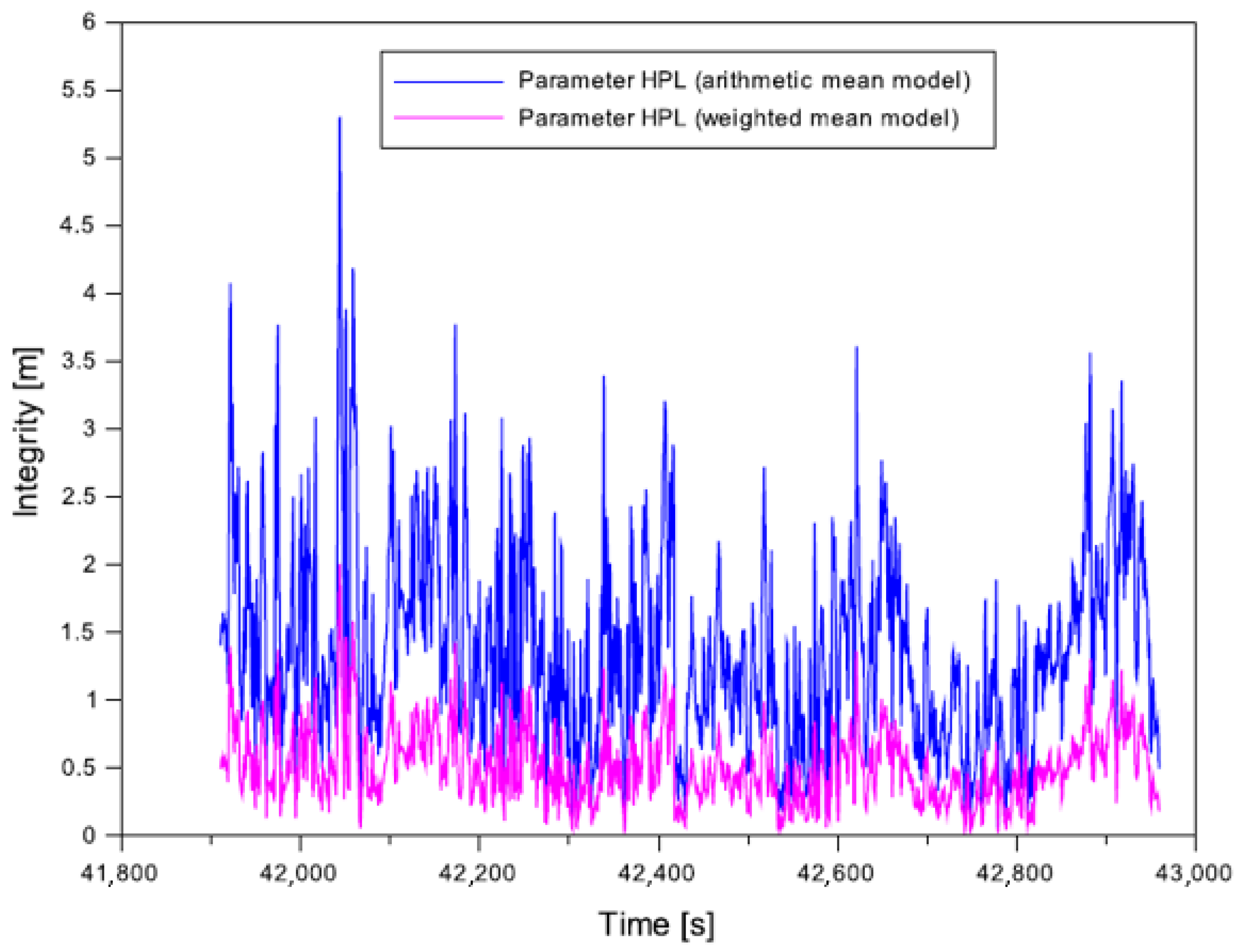
The integrity parameter HPL (Horizontal Protection Level) for navigation in the horizontal plane should not exceed 40 m for the SBAS APV-I and SBAS APV-II procedures;
-
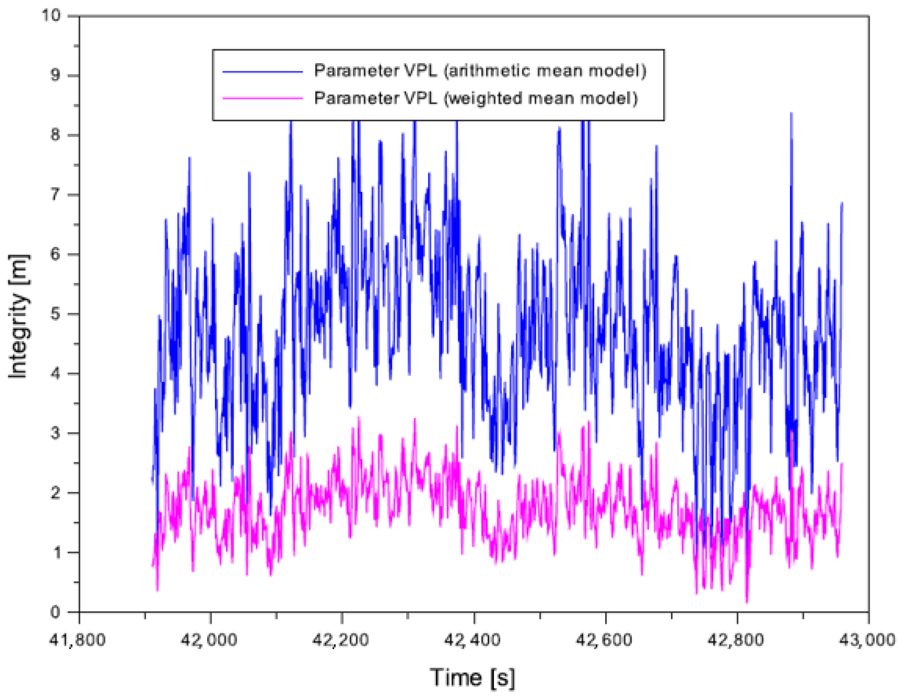
The integrity parameter VPL (Vertical Protection Level) for vertical navigation should not exceed 50 m for the SBAS APV-I approach procedure and 20 m for the SBAS APV-II procedure.
The research problem defined in the title of this paper refers mainly to the aviation aspect of the use of SBAS supporting systems, i.e., to the determination of the accuracy, continuity, availability, and integrity of SBAS positioning in aviation. In the territory of Poland, the EGNOS (European Geostationary Navigation Overlay Service) supporting system has been used for many years to improve GNSS positioning [4]. Apart from that, the Russian SDCM (System of Differential Correction and Monitoring) has also been used for several years [5]. Both these SBAS systems share a common coverage of the positioning range in the area of Poland and thus they may also be used in the realisation of aviation experiments and analysing the SBAS positioning quality in this part of Europe. The EGNOS and SDCM systems have been used multiple times in academic publications related to the subject literature. Research projects where all the quality parameters of EGNOS positioning in aviation were determined may be found in publications [6,7,8,9,10,11,12,13,14,15,16,17]. On the other hand, the accuracy parameter alone was calculated and discussed in publications [4,18,19,20,21,22,23,24,25,26], while the integrity parameter was determined and presented in publications [3,27,28,29,30,31]. It is worth adding that the referenced research projects were conducted in Poland and, in one case, in Slovakia. It should also be noted that the scope of research referred either to conducting an aviation experiment or a static GNSS measurement with use of EGNOS corrections. Kinematic flight tests were performed mainly in eastern Poland, i.e., at the border of the range of availability of EGNOS system corrections in Eastern Europe. At least one and sometimes more GNSS receivers with the function of EGNOS tracking and measurement were always installed in the aerial vehicles. On the other hand, static GNSS measurements were conducted in the vicinity of airports and landing areas at various latitudes. This allowed for analysing the SBAS signal quality and verifying its potential usefulness in aviation applications.
The EGNOS system is also used in Europe and northern Africa to improve GNSS positioning quality for the purposes of air transport. Publications [32,33,34] present the positioning quality results for the territory of Algeria. On the other hand, in Europe [35,36,37,38,39,40,41,42,43,44,45,46] various aspects of analysing the GNSS positioning quality in aviation were also presented. What is worth noting is that the publications referenced above very often emphasised the fact that the task of EGNOS is to correct the code positioning of the GPS s part of the SPP (Single Point Positioning) method.
On the other hand, the SDCM system was far less frequently used in aviation applications. Here, it is worth mentioning publication [5], which presented a combined EGNOS+SDCM positioning solution as part of the positioning of UAV (Unmanned Aerial Vehicles). Moreover, publications [47,48,49,50] describe the characteristics of the SDCM system in terms of its application as a system to support the SBAS in air navigation. On the other hand, publication [51] presented the influence of the SDCM system of the availability parameter of SBAS positioning for the entire globe, while publication [52] discussed the influence of the SDCM system on the determination of the accuracy, availability, and integrity of GNSS positioning for the territory of South Korea. Publications [53,54,55,56] presented the influence of the SDCM system on the accuracy parameter of GPS positioning and of positioning with the GPS/GLONASS (Globalnaya Nawigacionnaja Sputnikovaya Sistema) systems. Yet another study [57] analysed the possibilities to use the SDCM supporting system in aerial operations in the territory of Romania in reference to the EGNOS and GAGAN (GPS Aided Geo Augmented Navigation) systems. A very interesting numerical solution was presented in publication [58]. Namely, it presented selected models of SBAS corrections for the supporting systems: SDCM, EGNOS, WAAS (Wide Area Augmentation System), MSAS (Multi-functional Satellite Augmentation System) and GAGAN, followed by their comparison. Article [59] discussed a new algorithm to modify the SDCM corrections for the purposes of their application to improve GLONASS positioning, whereas study [60] presented the influence of the SDCM solution on the determination of the equipment delay for the receiver between GPS/GLONASS systems.
The presented knowledge status analysis [1,2,3,4,5,6,7,8,9,10,11,12,13,14,15,16,17,18,19,20,21,22,23,24,25,26,27,28,29,30,31,32,33,34,35,36,37,38,39,40,41,42,43,44,45,46,47,48,49,50,51,52,53,54,55,56,57,58,59,60] allows us to draw the following conclusions:
-
The quality parameters of SBAS positioning are very important in terms of the application of SBAS systems in aviation;
-
The studies of quality parameters of SBAS positioning were usually based on a single SBAS navigation solution;
-
In Poland, the EGNOS supporting system was generally used in practically all the referenced research projects [3,4,5,6,7,8,9,10,11,12,13,14,15,16,17,18,19,20,21,22,23,24,25,26,27,28,29,30,31];
-
In research projects conducted in Europe and Africa [32,33,34,35,36,37,38,39,40,41,42,43,44,45,46], the EGNOS system was also used as a system to support the SBAS;
-
Subject literature [47,48,49,50,51,52,53,54,55,56,57,58,59,60] shows that the SDCM system was less widely applied in practice in aviation than the EGNOS system;
-
However, it also demonstrates [47,48,49,50,51,52,53,54,55,56,57,58,59,60] that the SDCM system may provide an alternative for the EGNOS system in GNSS satellite positioning;
-
The area of the territory of Poland is covered by the common range of corrections of EGNOS and SDCM, so that both SBAS supporting systems are used in GNSS satellite positioning.
Additionally, the presented analysis of the state of knowledge [1,2,3,4,5,6,7,8,9,10,11,12,13,14,15,16,17,18,19,20,21,22,23,24,25,26,27,28,29,30,31,32,33,34,35,36,37,38,39,40,41,42,43,44,45,46,47,48,49,50,51,52,53,54,55,56,57,58,59,60] also allows us to define the missing elements that constitute current research problems for the proposed topic of the article, i.e.:
-
There is no common solution for EGNOS and SDCM positioning in the context of aviation;
-
In numerical terms, no algorithms exist that would integrate the single EGNOS and SDCM solutions for the purposes of determination of the resultant position of the aerial vehicle;
-
In terms of aviation, there are also no available mathematical formulas that would enable the determination of the accuracy, continuity, availability, and integrity from a combined navigation solution of EGNOS and SDCM;
-
In aviation, more research is required to determine the SBAS positioning quality for specific phases of flight, e.g., landing approach;
-
Another missing element in the aviation context is the increased number of trainings of flight crews in Multi-SBAS positioning for aviation purposes.
The conducted analysis of the state of knowledge together with preliminary conclusions and identification of the missing elements in the research on the subject matter of this article revealed that it is necessary to develop and implement a new SBAS navigation solution in aviation based on the integration of data from EGNOS and SDCM. Due to that, this article presents a modified plan of an SBAS navigation solution based on the Multi-SBAS positioning concept. Namely, first of all, the Multi-SBAS concept enables to determine the resultant coordinates of an aerial vehicle, and secondly, it allows for the integration of single SBAS solutions. Based on this assumption, single SBAS navigation solutions are combined through the appropriate model of the resultant position of the aerial vehicle. Subject literature demonstrates [61] that the optimum model for the determination of the resultant position of an aerial vehicle is the weighted mean model. It should be noted that this approach will also require the modification of the scheme of determining the quality parameters of SBAS positioning. Moreover, it may be assumed that the accuracy, continuity, availability, and integrity parameters of SBAS positioning will also have the nature of resultants if this approach is used. Here it should be explained why this calculation strategy is so beneficial. This is due to the fact that the determined resultant accuracy, continuity, availability, and integrity parameters of SBAS positioning will be defined with at least one degree of freedom [61]. This means that, in statistical terms, the presented solution, has one redundant measurement and it involves calculation control, which will enable, at least, to reduce gross errors in a single SBAS solution, if such errors occur. It is still necessary to pay attention to the very scheme of connecting individual SBAS solutions in the data integration model. Namely, the weighted mean model used to integrate individual SBAS solutions depends on the weights assigned to measurements. In the presented study, weighting was applied as a function of the inverse number of tracked GPS satellites for which corrections were developed from EGNOS and SDCM geostationary satellites. This weighing scheme is important due to several reasons: firstly, it is easy to implement in calculations and does not require the user to possess specialist statistical knowledge; secondly, most GNSS receivers in the process of processing GNSS observations provides the users with access to information about the current number of tracked GPS satellites; and thirdly, the measurement weight model will also depend on the geometric coefficient PDOP (Position DOP). The modified Multi-SBAS positioning model presented here may be used to improve the quality of SBAS positioning in aviation. Apart from that, the proposed Multi-SBAS solution may also be used in the certification process of SBAS supporting systems in aerial navigation.
The main contribution of the authors of the article consists in:
-
Defining a multi-system Multi-SBAS solution that takes into account individual EGNOS and SDCM solutions to determine the model of the resultant position of an aerial vehicle;
-
Employing the Multi-SBAS solution to calculate the quality parameters of the aerial vehicle, i.e., the accuracy, continuity, integrity, and availability parameters;
-
Developing a weighting plan to integrate and combine individual SBAS solutions to the Multi-SBAS model;
-
Conducting navigation analyses that confirm the correctness of the developed research methodology.

2. Research Method

This section presents the algorithm of the mathematical model for the determination of the resultant coordinates of aerial vehicles from the Multi-SBAS solution. Additionally, the modified equations for the determination of the quality parameters of SBAS positioning in aviation are presented.

2.1. Mathematical Model of Multi-SBAS Solution for Aircraft Position using EGNOS and SDCM Data

The presented approach employs the multi-system Multi-SBAS solution. The analysed example refers to the EGNOS and SDCM supporting systems. This will constitute the basis for the determination of the model of the resultant position of an aerial vehicle:
{ B m = α E · B E G N O S   +   α S · B S D C M α E   +   α S L m = α E · L E G N O S   +   α S · L S D C M α E   +   α S h m = α E · h E G N O S   +   α S · h S D C M α E   +   α S
where:
  • B E G N O S —geodetic latitude from an individual SBAS/EGNOS solution [5,10,62],
  • B S D C M —geodetic latitude from an individual SBAS/SDCM solution [5,10,62],
  • L E G N O S —geodetic longitude from an individual SBAS/EGNOS solution [5,10,62],
  • L S D C M —geodetic longitude from an individual SBAS/SDCM solution [5,10,62],
  • h E G N O S —ellipsoidal height from an individual SBAS/EGNOS solution [5,10,62],
  • h S D C M —ellipsoidal height from an individual SBAS/SDCM solution [5,10,62],
  • α E 
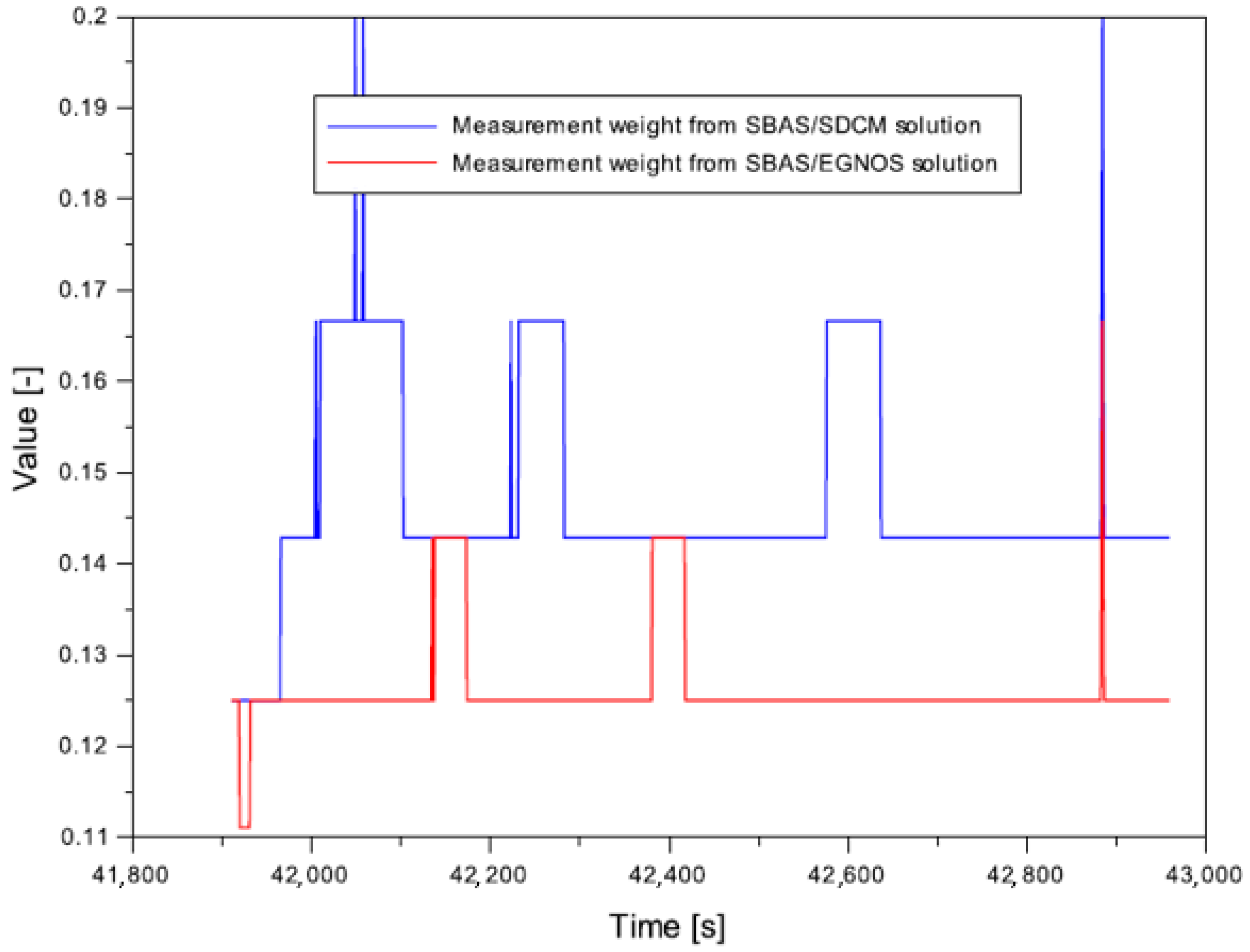
—measurement weight from the SBAS/EGNOS solution,
  • α S —measurement weight from the SBAS/SDCM solution.
The measurement weight was defined as a function of the number of tracked GPS satellites, for which EGNOS and SDCM corrections were recorded, as presented below:
α E = 1 n s E G N O S     i     α s = 1 n s S D C M
where:
  • n s E G N O S 
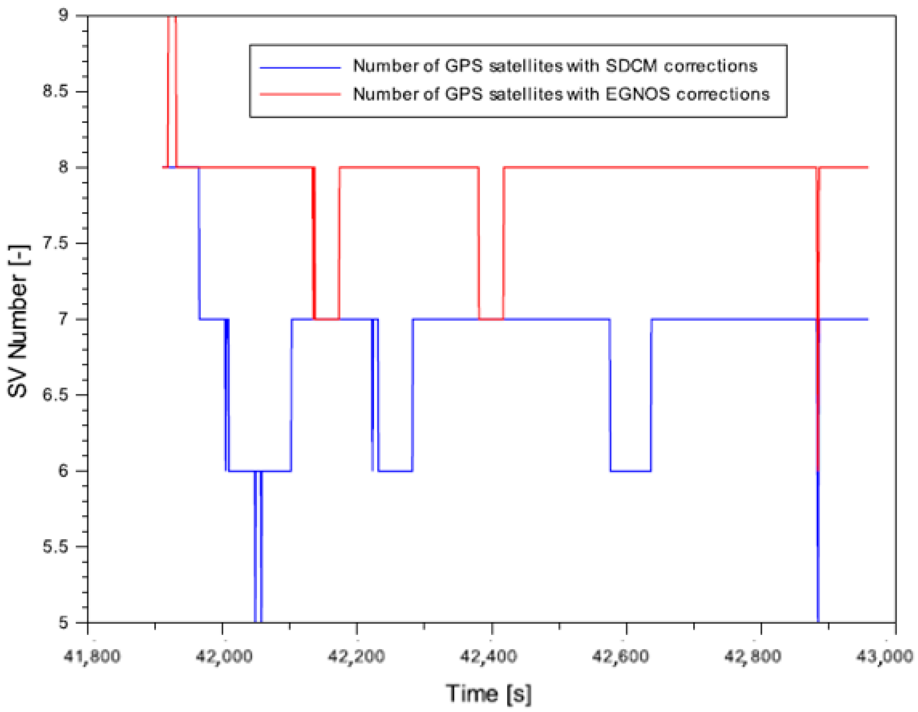
is the number of GPS satellites for which EGNOS corrections were defined in the SBAS/EGNOS solution,
  • n s S D C M is the number of GPS satellites for which EGNOS corrections were defined in the SBAS/SDCM solution.
Equation (1) describes the weighted mean model, taking into account the measurement weights ( α E , α s ) that enable the integration of individual EGNOS and SDCM navigation solutions. Additionally, it should be noted that the resultant model of the position of the aircraft is expressed in ellipsoidal coordinates BLh (B-Latitude, L-Longitude, and h-ellipsoidal height). The standard deviations for coordinates (Bm, Lm, and hm) will also be calculated for the determined resultant position of the aerial vehicle, in the form:
{ δ B = [ v B , E G N O S · α E · v B , E G N O S   +   v B , S D C M · α S · v B , S D C M ] n     1 δ L = [ v L , E G N O S · α E · v L , E G N O S   +   v L , S D C M · α S · v L , S D C M ] n     1 δ h = [ v h , E G N O S · α E · v h , E G N O S   +   v h , S D C M · α S · v h , S D C M ] n     1
where:
  • v B   
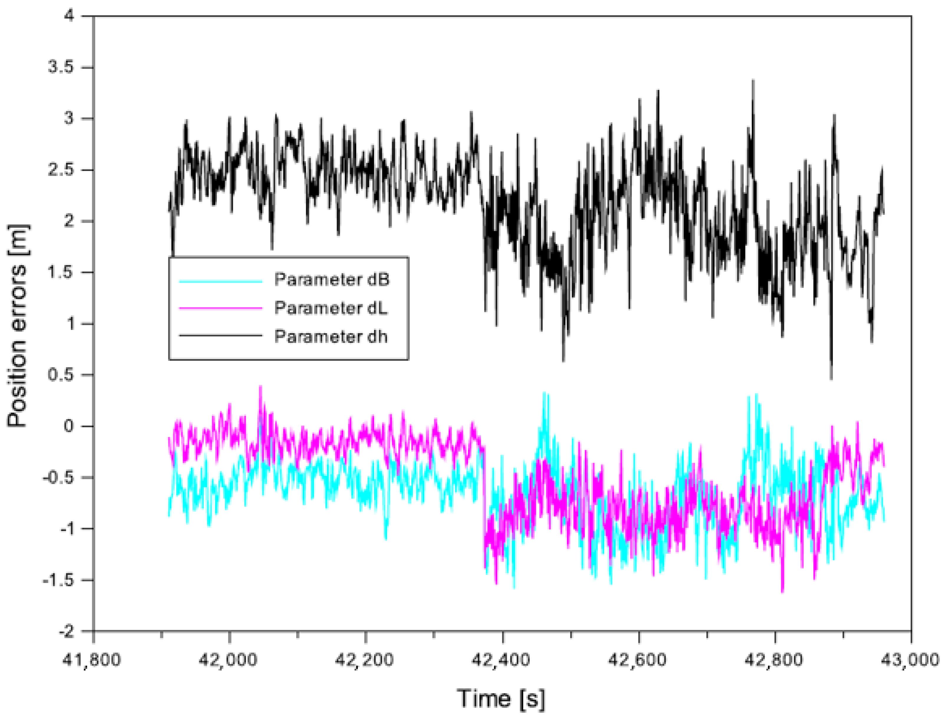
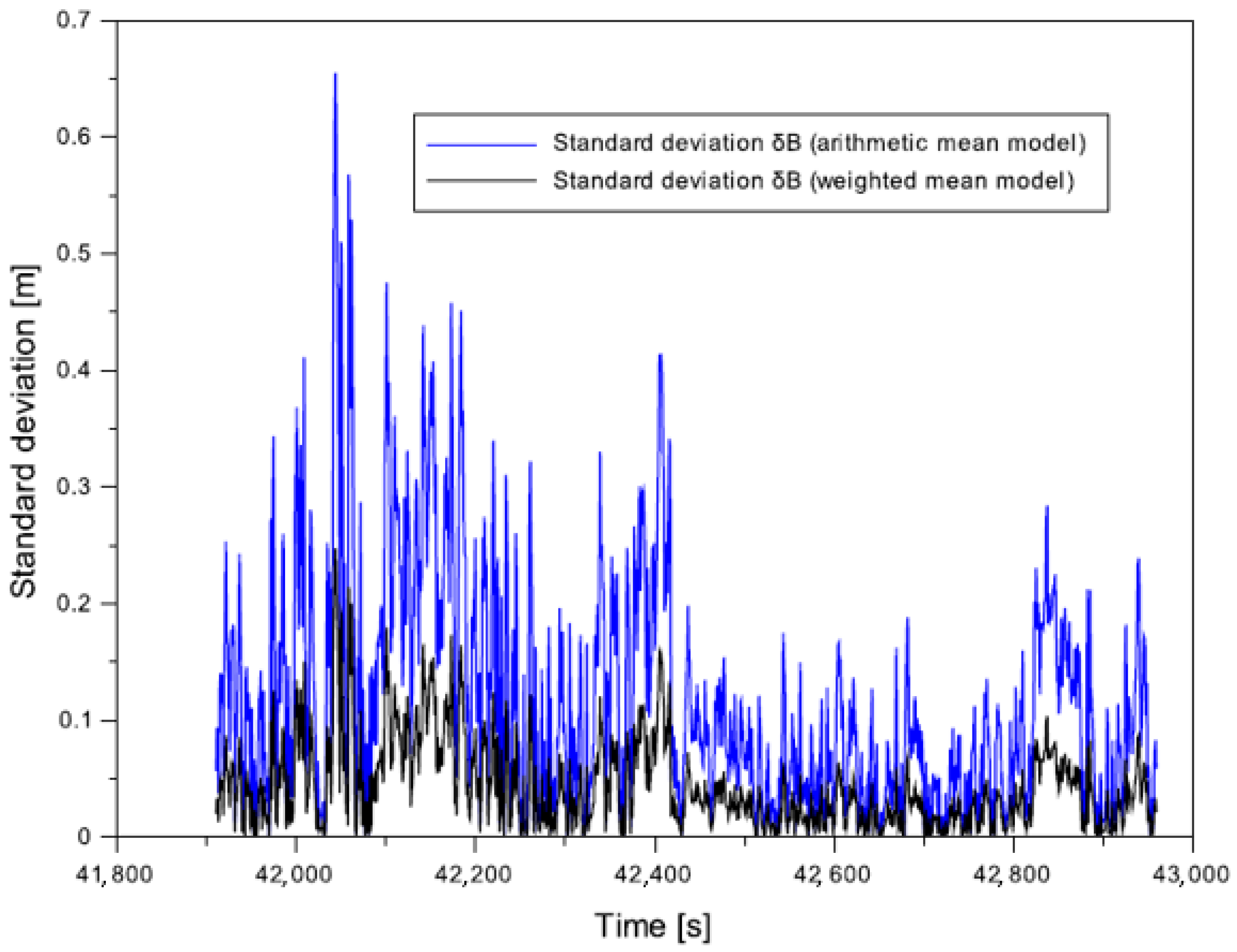
—corrections along the B axis,
  • v B , E G N O S = B E G N O S B m ,
  • v B , S D C M = B S D C M B m ,
  • v L 
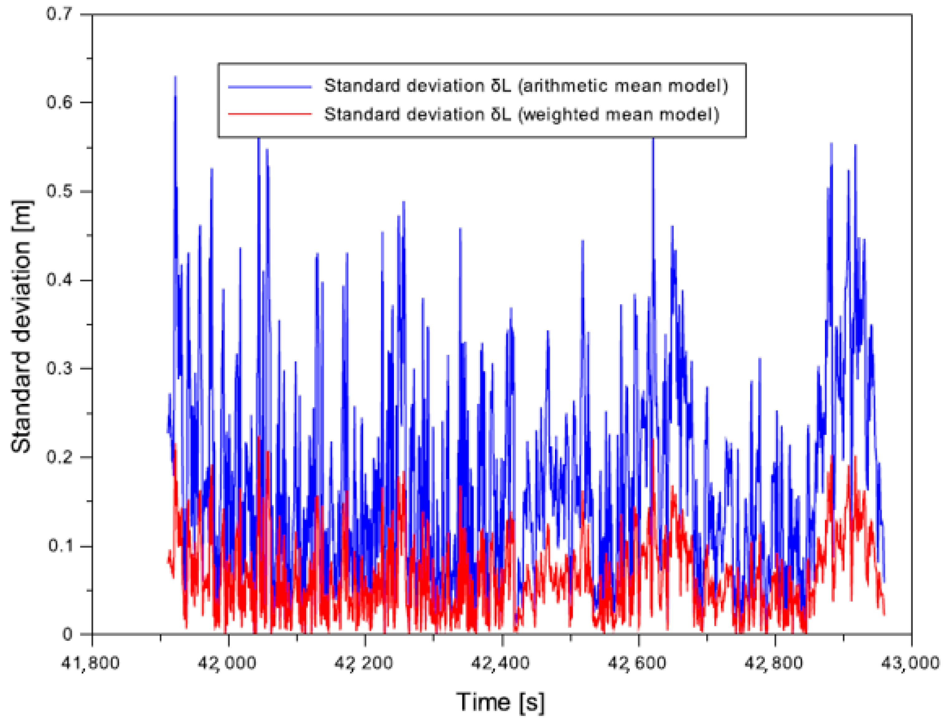
—corrections along the L axis,
  • v L , E G N O S = L E G N O S L m ,
  • v L , S D C M = L S D C M L m ,
  • v h   
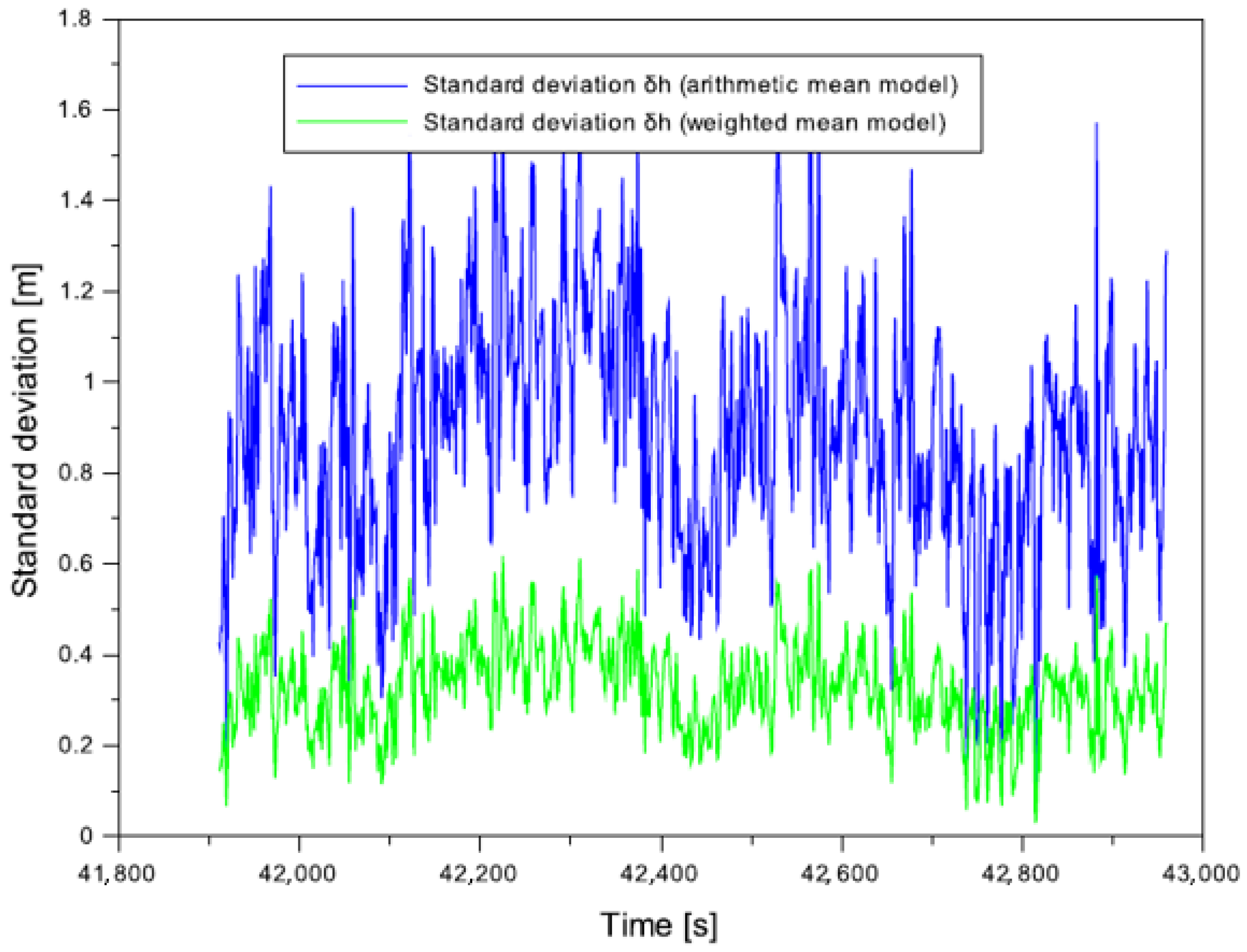
—corrections along the h axis,
  • v h , E G N O S = h E G N O S h m ,
  • v h , S D C M = h S D C M h m ,
  • n —number of measurements, n = 2 ,
  • n 1 —number of degrees of freedom.
The standard deviations calculated for the resultant position of the aerial vehicle will determine the internal accuracy of the presented mathematical Equation (1).

2.2. Mathematical Model of Multi-SBAS Solution for Parameters of Quality Positioning

The analysis of the quality parameters of Multi-SBAS positioning in the presented research method is based on the determination of four parameters: accuracy, continuity, availability, and integrity of SBAS positioning. The values of the accuracy parameter of positioning the aerial vehicle were expressed in the ellipsoidal system BLh. For the purposes of this study, the following mathematical algorithms were used:
-
for the accuracy parameter:
[ d B d L d h ] = [ B m B R T K L m L R T K h m h R T K ]
where:
  • ( d B , d L , d h ) —accuracy of positioning the aerial vehicle [63],
  • ( B m , L m ,   h m ) —the resultant coordinates of the aerial vehicle determined with use of solution (1),
  • ( B R T K , L R T K , h R T K ) —the coordinates of the aerial vehicle calculated with use of the RTK (Real Time Kinematic) differential technique in the OTF (On The Fly) mode [61,62].
Additionally, for the ( d B ,   d L ,   d h ) parameters, the RMS (Root Mean Square) error was calculated [64]. It expresses the statistical measure of the accuracy of the determined resultant coordinates of the aerial vehicle. The value of the RMS error was calculated for the results of the dB, dL, and dh parameters in the following way:
{ R M S d B = [ d B 2 ] N R M S d L = [ d L 2 ] N R M S d h = [ d h 2 ] N
where:
  • R M S d B —RMS error for the calculated accuracy of the determined resultant component B of the aerial vehicle,
  • R M S d L —RMS error for the calculated accuracy of the determined resultant component L of the aerial vehicle,
  • R M S d h —RMS error for the calculated accuracy of the determined resultant component h of the aerial vehicle,
  • N —number of measurement epochs.
Another essential factor for the determination of the positioning accuracy in 3D space is the determination of the resultant position error d r . In the analysed example, the d r parameter will define the shift vector of the resultant coordinates of the aerial vehicle with respect to the reference trajectory of the flight. The d r parameter may be calculated from the mathematical Equation (6), as presented below:
d r = d B 2   +   d L 2   +   d h 2
where:
  • d r 
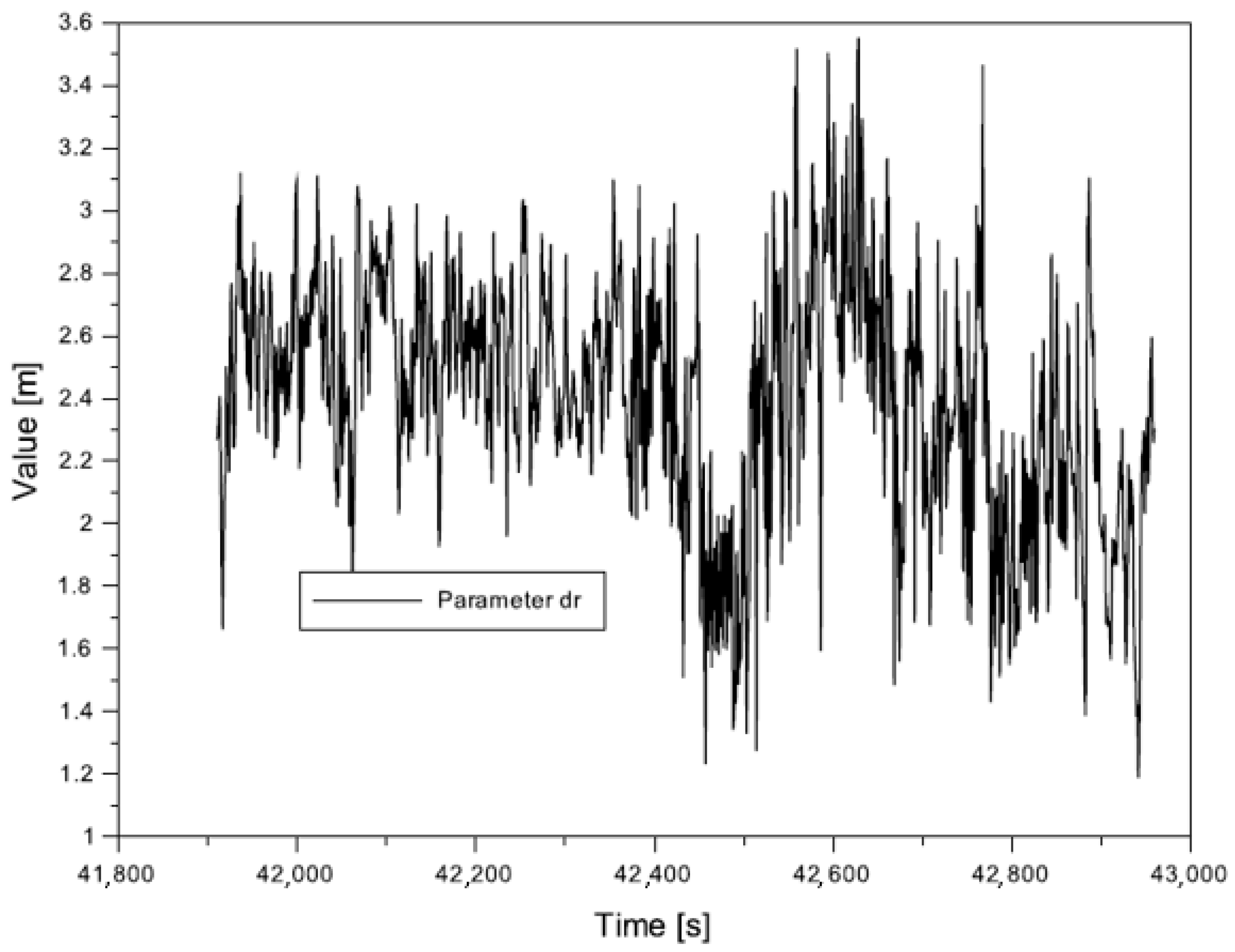
—resultant position error in 3D space.
-
for the availability parameter:
A m = A E G N O S · α E   +   A S D C M · α S α E   +   α S
where:
  • A m —resultant availability of Multi-SBAS positioning,
  • A E G N O S   —positioning availability from the SBAS/EGNOS solution,
  • A E G N O S = 100 % · t   E / a c c i d e n t t a l l ,
  • A S D C M —positioning availability from the SBAS/SDCM solution,
  • A S D C M = 100 % · t S / a c c i d e n t t a l l ,
  • t E / a c c i d e n t —outage duration in the SBAS/EGNOS solution,
  • t S / a c c i d e n t —outage duration in the SBAS/SDCM solution,
  • t a l l —total time of functioning of the given SBAS system.
The determined value of the availability parameter A m is dimensionless; optionally it may be expressed as percentage.
-
for the continuity parameter:
C m = C E G N O S · α E   +   C S D C M · α S α E   +   α S
where:
  • C m —resultant continuity of Multi-SBAS positioning,
  • C E G N O S —positioning continuity in SBAS/EGNOS solution,
  • C E G N O S = P E Δ t E · t o b s E ,
  • C S D C M —positioning continuity in SBAS/SDCM solution,
  • C S D C M = P S Δ t S · t o b s S ,
  • P E —probability of maintaining continuity in SBAS/EGNOS solution,
  • P S —probability of maintaining continuity in SBAS/SDCM solution,
  • Δ t E —time interval unit in SBAS/EGNOS solution,
  • Δ t S —time interval unit in SBAS/SDCM solution,
  • t o b s E —total time of observations in SBAS/EGNOS solution,
  • t o b s S —total time of observations in SBAS/SDCM solutions.
Actually, the determined value of the continuity parameter C m defines the number of failures and interruptions in the functioning of the Multi-SBAS solution. What is worth noting is the fact that this value is dimensionless.
-
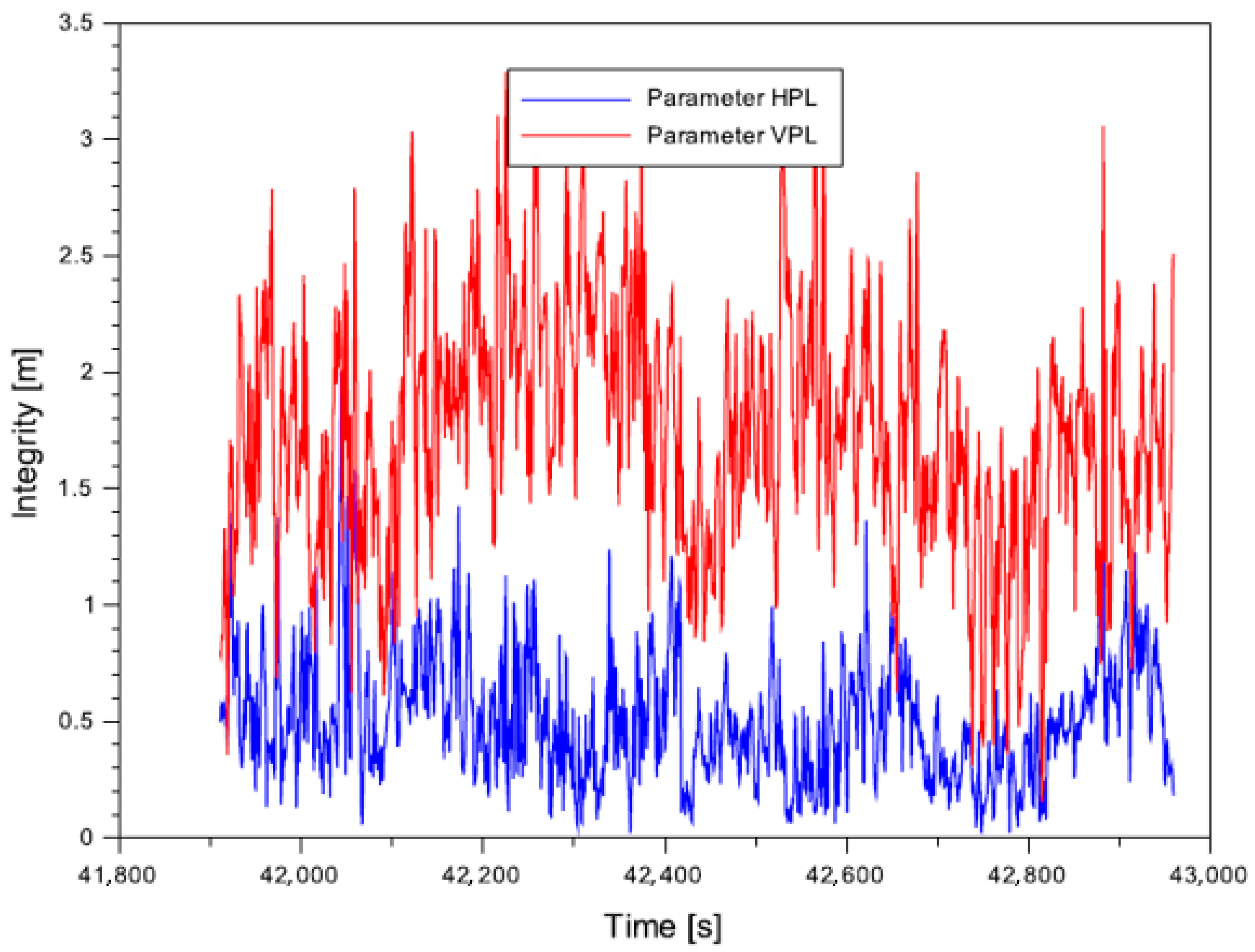
for the integrity parameter:
{ H P L = K H · δ B m 2   +   δ L m 2 V P L = K V · δ h m
where:
  • K H —proportionality coefficient in the horizontal plane for SBAS APV type approach: K H = 6.00 [2],
  • K V —proportionality coefficient in the vertical plane for SBAS APV type approach: K V = 5.33 [2],
  • ( δ B ,   δ L ,   δ h ) 
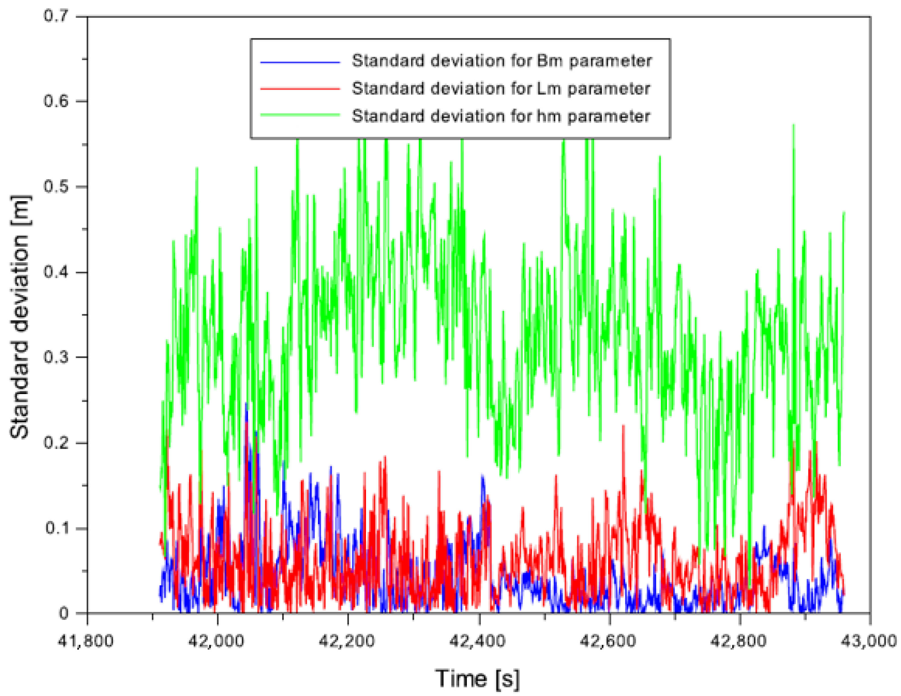
—standard deviations for coordinates (Bm, Lm, hm) from the solution of (3),
  • H P L —level of positioning integrity in the horizontal plane,
  • V P L —level of integrity of vertical positioning.
Equation (9) describes the integrity of positioning for the Multi-SBAS solution with use of the HPL and VPL parameters.

3. Research Experiment

In reference to the analysis of the state of knowledge concerning the application of SBAS supporting systems in aviation, this study focused on the final stage of flight being the landing approach and landing. To this end, first a flight experiment was conducted, followed by the elaboration of the GNSS data, and finally, the necessary numerical analyses were conducted for the research methodology proposed in the paper.
The first stage consisted of performing a test flight. The flight was conducted jointly by a research team composed of employees of the Polish Air Force University, the University of Warmia and Mazury, and the Aero Club of Warmia-Mazury. The test flight was performed with a Diamond DA 20-C 31 aircraft on 31 October 2020, in north-eastern Poland. A dual-frequency geodetic receiver Septentrio AsterRx2i was installed on board of the aircraft. The flight lasted from 07:57:07 h (28,627 s) to 11:55:59 h (42,959 s) according to GPS Time (GPST). The Septentrio receiver recorded GPS satellite data at 1-s intervals. The obtained data were used to calculate the position of the aerial vehicle and the quality parameters of satellite positioning based on Equations (1)–(9). During the entire flight, the scope of changes in the geodetic latitude B ranged from 53.458121° to 54.097633°, while the scope of geodetic longitude L was in the range from 20.363363° to 22.982004°. The ellipsoidal height during the flight ranged from 139 m to 605 m. Additionally, the momentary velocity of the flight of the Diamond aircraft along the B axis ranged from 0 to 58 m/s, for the L component from 0 to 96 m/s, and along the h axis from 0 to 9 m/s.
An important element of the description of the flight experiment was the information about atmospheric conditions, i.e., respectively, the tropospheric and ionospheric conditions. The analysis of meteorological conditions was based on the data obtained from the weather station located in Olsztyn [65]. On the 31 October 2020, the air temperature in north-eastern Poland fluctuated between 6 °C and 10 °C, and the mean temperature was 8 °C. The highest temperature was noted at 11:30. There were heavy clouds, but the largest cloud coverage was noted after the end of the experiment, i.e., after 12. The wind was weak and moderate, from the western and north-western directions. No fog was observed during the flight. Air humidity ranged from 76% to 100%, with the mean value of 90%. As it was in the case of cloud cover, the lowest value of air humidity was noted during the realisation of the test flight. The atmospheric pressure in north-eastern Poland was initially 1017 hPa, and it increased in the subsequent hours. The highest value of air pressure, i.e., 1024 hPa, was recorded at 12:00 h.
As for the state of the ionosphere, the value of the Kp index for the 31 October 2020 was presented. The Kp index is a parameter that defines the radiation of solar wind particles that affect the magnetic field of the Earth [66]. Its value allows us to find out whether geomagnetic storms that might cause disturbances in the GNSS signal occurred during the experiment. During the flight of the Diamond, from 07:57:07 h (28,627 s) to 11:55:59 h (42,959 s) according to GPS Time (GPST) two values of the Kp index were determined: 2.34 at 7:50 h and 2.00 at 10:50 h. Thus, it may be stated that the values of the Kp index during the realisation of the experiment were low. Data related to the Kp index were downloaded from the website https://www.swpc.noaa.gov/products/planetary-k-index (accessed on 30 November 2021) [67]. With regard to the status of the ionosphere, the values of the VTEC (Vertical TEC) parameter [18,68,69] were also determined during the flight. Table 1 shows the results of VTEC parameter with time resolution of 1 h based on IONEX (IONosphere map EXchange) product from the Center for Orbit Determination in Europe (CODE) [70]. The VTEC parameter varied from 9.2 TECU (Total Electron Content Unit) to 22.6 TECU during the test flight. The highest VTEC value was at 12:00 and the lowest at 07:00 GPST.
As the article analyses the phases of landing approach and landing, further sections of the paper will focus on these stages of flight. In order to determine the quality of the Multi-SBAS satellite positioning during the approach to landing, the observations and GNSS navigation data recorded from 11:38:31 h (41,911 s) to 11:55:59 h (42,959 s) according to system time GPST were used. Figure 1 shows the horizontal trajectory of the landing approach of the Diamond aircraft that was recorded between 11:38:31 h and 11:55:59 h. During the landing approach, the geodetic latitude coordinate took the values from 53.791864° to 53.774913°. At the same time, the geodetic longitude coordinate L ranged from 20.408362° to 20.460093°. The values of the horizontal coordinates (B, L) were determined with use of Equation (1).
The next illustration-Figure 2 shows the characteristics of the vertical trajectory of the flight during the aircraft landing procedure, in the period from 11:38:31 h (41,911 s) to 11:55:59 h (42,959 s) according to system time GPST. The ellipsoidal height h during the approach to landing changed from 515 m to 163 m. The values of the vertical coordinate h were determined with use of Equation (1).
Then, Figure 3 shows the number of GPS satellites for which corrections were developed respectively from SDCM and EGNOS geostationary satellites. During the landing approach procedure, the Septentrio on-board receiver recorded from 6 to 9 GPS satellites with EGNOS corrections, as well as 5 to 8 GPS satellites with SDCM corrections. Additionally, the mean number of tracked GPS satellites with SDCM corrections during the landing approach was 6, while the number of GPS satellites with EGNOS corrections was 7. The analysis of the results presented in Figure 3 reveals that the EGNOS system sent corrections to a larger number of GPS satellites than the SDCM system.
The conducted flight test also involved the determination of the dilution of precision coefficient in 3D space–the geometric PDOP (Position DOP) coefficient. The PDOP is a coefficient that is used in GNSS systems to define the influence of the spatial location of GNSS satellite on the accuracy of the determined three-dimensional position [71]. In the present study, the PDOP was determined for an individual SBAS solution, i.e., for the EGNOS and SDCM systems. Figure 4 shows the values of the PDOP coefficient from an individual SBAS solution, i.e., EGNOS and SDCM during the phase of approach to landing of an aerial vehicle. The value of the PDOP coefficient for a single SBAS/EGNOS solution ranged from 1.8 to 2.8, with a mean value of 2.2. For a single SBAS/SDCM solution, the value of this coefficient ranged from 2 to 3.6, while the mean value was also 2.2. The values of the PDOP coefficient obtained for both single SBAS/EGNOS and SBAS/EGNOS did not exceed 3, which means that the observation conditions during the test flight were very good.
The second stage of research consisted in the pre-processing of the recorded GNSS satellite data. During the test flight, the on-board receiver Septentrio AsterRx2i was used to collect and record the GPS observations to calculate the position of the aircraft. In order to perform the pre-processing of the analysed material, GPS satellite data were saved on portable data carriers and then uploaded to the computer. After that, the data were converted from the binary format to the RINEX format. As a result, two RINEX files in the GPS system were obtained: observation RINEX and navigation RINEX. At this stage, the corrections from the EGNOS satellite number S123 were also applied as well as SDCM corrections from satellite number S125. The corrections are published on the server ftp://serenade-public.cnes.fr/SERENAD0 (accessed on 30 November 2021) [72]. The format of the EGNOS and SDCM corrections was saved in files with the “EMS” extension.
The prepared GPS navigation and observation data in the RINEX format and the SBAS corrections in the EMS format were then used in the third phase of research. At this stage, calculations were performed with use of the RTKLIB software v.2.4.3 [73] and the programming language Scilab v. 6.0.0 [74]. Calculations began in the RTKLIB navigation application. Here, the RTKPOST library was used to determine the position of the aerial vehicle from a single SBAS solution (EGNOS and SDCM). The SBAS positioning algorithm in the RTKPOST software is based on the SPP code method with the implementation of SBAS corrections [62]. For a single SBAS solution, two calculation reports were generated: one from a single GPS solution with EGNOS corrections and the other from a single GPS solution with SDCM corrections. Due to the fact that the determination of the parameters of the positioning of aerial vehicle requires us to determine the reference trajectory of the flight, the reference position of the Diamond DA 20-C aircraft was determined from the RTK-OTF solution in the RTKLIB software. The RTK-OTF solution adopted in the RTKLIB application is the “MOVING BASE” computational module [75]. The RTK-OTF solution uses the RINEX observation data from the on-board receiver and the reference station and the GPS navigation message. As for the reference station, RINEX observation data from the OPNT base station [76] located in Olsztyn were used.
The generated reports from a single SBAS solution and the RTK-OTF differential technique were then used to conduct further numerical calculations, i.e., to determine the resultant position of the aerial vehicle and the resultant quality parameters of Multi-SBAS positioning in the landing approach procedure. Calculations were performed in the Scilab programming language. Calculations performed in the Scilab software started with importing the reports generated in the RTKPOST application. Then, the necessary determined navigation parameters in the period from 11:38:31 h (41,911 s) to 11:55:59 h (42,959 s) according to system time GPST were selected. The next stage consisted in the development and application of the weighted mean model in compliance with the adopted research methodology. This stage involved the determination of: the resultant coordinates of the aerial vehicle, the standard deviations for these resultant coordinates, and the resultant quality parameters of positioning from the multi-system SBAS solution. The calculations took into account the mathematical algorithms for Equations (1)–(9). The results of the calculations performed in Scilab software are presented in form of numerical data, tables and graphics in Section 4. It is worth mentioning, that some additional numerical calculations were also conducted in the Scilab software to confirm the correctness of the proposed research method. They are discussed in Section 5.

4. Results

Section 4 presents the results of the conducted research. Firstly, the results of the measurement weights determined with use of Equation (2) are presented.
The values of measurement weights obtained from a single SDCM ranged from 0.125 to 0.2, while those from EGNOS solution ranged from 0.111 to 0.166. To analyse the results presented in Figure 5, it is worth referring to the results shown in Figure 3, i.e., to the number of GPS satellites with SDCM and EGNOS corrections. One may say that, as the measurement weight increases, the number of GPS satellites use in the EGNOS or SDCM solutions decreases. This correlation is also true for the reverse direction, so that, as the number of GPS satellites tracked by the receiver increases, the measurement weight decreases, as it is described in Equation (2). It should also be noted that the relation described by the mathematical Equation (2) changes exponentially.
Then, Figure 6 illustrates the obtained values of standard deviation calculated with use of Equation (3). The values of the ( δ B ,   δ L ,   δ h ) parameters are determined for the resultant coordinates of the aerial vehicle in the Multi-SBAS solution. The maximum values of the ( δ B ,   δ L ,   δ h ) parameters are, respectively: for component B up to 0.25 m, for component L up to 0.22 m, and for component h up to 0.62 m. The analysis of the results presented in Figure 6 reveals that the highest values of standard deviation were obtained for the vertical component h. Moreover, the standard deviations of δ B were approximately 60% lower than values of δ h results. On the other hand, the standard deviations of δ L were approximately 65% lower than those of the δ h parameter.
Figure 7 shows the results of Multi-SBAS positioning accuracy for the position of the aerial vehicle. The obtained values of the accuracy of positioning with use of multi-system SBAS solutions were obtained from Equation (4). These results were expressed in form of ellipsoidal coordinates BLh. Obviously, it should be noted that in order to determine the positioning accuracy, the resultant coordinates of the aerial vehicle obtained from the Multi-SBAS solution were compared with the reference position of the flight calculated with use of the RTK-OTF differential technique. The accuracy of the determination of the geodetic latitude B from the Multi-SBAS solution during the landing approach procedure ranged from −1.58 m to +0.33 m, whereas the mean accuracy for the geodetic latitude component B equalled −0.65 m. On the other hand, for the geodetic longitude L, the positioning accuracy ranged from −1.62 m to +0.40 m, with a mean value of −0.50 m. The accuracy of positioning the vertical component h from the Multi-SBAS solution ranged from +0.45 m to +3.38 m. The mean value of positioning accuracy along the h axis equalled +2.18 m. The comparison of the resulting values of the ( d B ,   d L ,   d h ) parameters revealed that the accuracy values d B were approximately 70% lower than the obtained results of d h position errors. Additionally, the values of accuracy of d L were 77% lower than the d h position errors.
Important parameters that must be determined in the accuracy analysis are the RMS errors. The values of these errors were calculated from the formulas provided in Equation (5). Based on the conducted research, it was determined that the lowest values of the RMS error were obtained along the L axis, and the highest one for the vertical component h. The values of the obtained RMS errors are presented in Table 2.
Additionally, the vector of coordinate shift d r on a 3D plane was determined for the accuracy parameter, according to Equation (6). The spread of the results of the vector of the shift in the position of the aerial vehicle from the multi-system Multi-SBAS solution ranged from 1.19 m to 3.55 m with a mean value of 2.39 m. It is worth noting that the factor that has the strongest influence on the results of the d r parameter are position errors, in particular the position errors for the h component. The lower the accuracy of the vertical component h becomes, the higher is the value of the shift vector d r . Obviously, the application of the square root function in Equation (6) reduces the increase in the d r parameter, but it is still noticeable, as shown in the results in Figure 8. As a result, it is necessary to continue solving and improving the algorithms for determining the position of an aerial vehicle, in particular for the vertical component h.
Equation (7) was used to calculate the availability of Multi-SBAS positioning for the analysed stage of flight of the aerial vehicle. In the conducted experiment, the availability of Multi-SBAS positioning was 100% through the entire procedure of landing approach and landing itself. Table 3 presents the results of the availability of positioning of the aerial vehicle from the Multi-SBAS solution. Availability is expressed in percent. Apart from that, Table 3 presents the results of calculating the continuity parameter from the Multi-SBAS solution. In this case, calculations were performed with use of Formula (8).
The continuity parameter takes into account the number of occurring outages in the functioning of SBAS supporting systems. Due to the fact that the subject of this study is the determination of the quality of Multi-SBAS positioning in the landing approach procedure, the conducted calculations were based on the probability of continuity for SBAS APV approach for the GNSS satellite technique in compliance with the requirements of ICAO, where the values P E Δ t E = P S Δ t S are the same and equal, respectively, from 1 · 10 6 15   s to 8 · 10 6 15   s [2]. The final continuity valuers from the Multi-SBAS solution ranged from 0.0000699 to 0.0005595.
Figure 9 presents the results of positioning integrity according to Formula (9). The integrity values were presented in form of the HPL and VPL security parameters. The HPL values in the landing approach procedure ranged from 0.02 m to 2.01 m, with the mean value of HPL of 0.51 m, while the VPL values ranged from 0.15 m to 3.29 m, with the mean value of 1.74 m. Thus, one may state that the proposed Multi-SBAS solution allowed for a significant increase in the value of the integrity parameter, so that the maximum value did not exceed 3.3 m. This is particularly important for the improvement of the safety of performing aviation operations, as integrity is a measure of trust in the obtained navigation solution of the position of the aerial vehicle obtained from the Multi-SBAS positioning solution.
Analysing the obtained HPL/VPL integrity parameters presented in Figure 9, it is worth to refer to the results of the positioning accuracy shown in Figure 7. The determination of the HPL/VPL values is mainly influenced by the standard deviations of the calculated aircraft coordinates [77]. The smaller the values of standard deviations, the smaller the HPL/VPL values are. Positioning accuracy, on the other hand, will mean by how much the determined aircraft coordinates are offset from the flight reference position. The smaller the difference of the compared coordinates from the SBAS and RTK-OTF solution, the higher the positioning accuracy.

5. Discussion

The aim of the discussion of the obtained research results is to highlight the advantages and the efficiency of the presented research method. First of all, the validity of the applied research method was verified, and then the influence of the obtained research results was highlighted in the context of the analysis of the state of knowledge.

5.1. Validity of the Applied Research Method

From the point of view of the applied research method, the first part of the discussion is the most important. In fact, demonstrating the validity of the presented research method requires conducting numerous additional comparative analyses for the parameters obtained from the mathematical Equations (1)–(9). Firstly, the obtained standard deviation results were evaluated and analysed. Figure 10, Figure 11 and Figure 12 show a comparison of the standard deviations obtained from the weighted mean model (see Equations (1)–(3)) and the arithmetic mean model [62]. The values from the weighted mean model were interpreted and presented in Figure 6. However, it is worth explaining why the weighted mean model is better than the arithmetic mean model for the standard deviation parameters. Namely, for the arithmetic mean model, the maximum standard deviation results are, respectively: 0.65 m for the δ B parameter, 0.63 m for the δ L parameter, and 1.69 m for the δ h parameter. As a result, comparative analysis reveals an improvement in the standard deviation results for the weighted mean model (Equations (1)–(3)). The results were improved by 61–65% for the horizontal components, and by 63% for the vertical component. This also demonstrates the validity of the adopted calculation strategy for the weighted mean model for the Multi-SBAS solution.
The further part of the discussion focuses on the comparative analysis of the accuracy parameter. Such comparative analysis was conducted of the accuracy from the weighted mean and the arithmetic mean models. Then, it was demonstrated how the weighted mean model improves the positioning accuracy for a single SBAS solution from the EGNOS supporting system. Figure 13 presents the comparison of the results of positioning accuracy in the 3D space, i.e., in fact of the d r parameter. The comparison was based on the results of the d r parameter from the weighted mean model and the arithmetic mean model. The values of the d r parameter from the weighted mean model were interpreted and presented in Figure 8. On the other hand, in Figure 13 the results of the d r parameter from the arithmetic mean model were added. The results of the comparative analysis of the d r parameter revealed that the weighted mean solution proposed by the authors improved the results of the d r parameter by 1% to 7% in comparison to the arithmetic mean model. It should be noted that this applies to accuracy in the 3D space, which is influenced to the greatest extent by errors in the position of ( d B ,   d L ,   d h ) , as shown in Equations (4) and (6).
As far as the comparative analysis of the accuracy between the weighted mean and arithmetic mean models is concerned, it is worth mentioning the position errors determined for the vertical component. Figure 14 presents the results of the comparison of the position errors for ellipsoidal height that were calculated with use of the weighted mean and arithmetic mean models. The values of the d h parameter from the weighted mean model were interpreted and presented in Figure 7. The results of the comparative analysis of the d h parameter revealed that the weighted mean solution proposed by the authors improved the results of the d h parameter by 1% to 14% in comparison to the arithmetic mean model. The effectiveness of the proposed solution for the weighted mean model and the vertical component is quite important for the phase of approach to landing and the landing itself. The results presented in Figure 14 demonstrate that the practical application of the weighted mean model yields better results than that of the arithmetic mean model. Improved vertical positioning accuracy is also crucial for the safety of flight.
Continuing the analysis of positioning accuracy, it should also be explained why the Multi-SBAS solution is far more effective than a single SBAS solution from the EGNOS supporting system. To do so, a comparison of the results for parameters ( d r ,   d h ) was conducted between the proposed weighted mean model and the single SBAS/EGNOS solution. Figure 15 shows the results of comparison of the d r parameter between the weighted mean model and a single SBAS/EGNOS solution. It is worth noting that the Multi-SBAS solution improves the value of the d r parameter by 1% to 37% in comparison to a single SBAS/EGNOS solution. The obtained improvements expressed in per cent are rather significant. Moreover, Figure 16 shows the results of comparison of the d h parameter between the weighted mean model and a single SBAS/EGNOS solution. As far as the positioning of the vertical component is concerned, the results obtained from the weighted mean model were significantly better than those from the single SBAS/EGNOS solution. The accuracy of the vertical component calculated with use of the weighted mean model improved by 1% to 73%. Based on these results, one may claim that the application of the Multi-SBAS positioning method in the accuracy analysis is justified. This solution is significantly more effective, especially as the results apply to aviation applications.
Further comparative analyses refer to two quality parameters of SBAS satellite positioning, in this context, respectively, to availability and continuity. The comparative analysis should be based on Formulas (7) and (8) from Section 2. Namely, it is necessary to demonstrate the reasonability of implementation of the Formulas (7) and (8) in the Multi-SBAS solution. Let us analyse a case where one of the single SBAS solutions loses its availability and continuity. In this case, it was assumed that no solution from the SDCM system was available for the given measurement epoch. Then, Equations (7) and (8) in the Multi-SBAS model will take the following form:
  { A m = A E G N O S · α E α E = A E G N O S C m = C E G N O S · α E α E = C E G N O S
What does the above Equation (10) actually mean in mathematical terms? If one single SBAS solution is lost (the SDCM solution, in this case), it will still be possible to determine the resultant values of availability and continuity, which will be determined from the EGNOS solution. It can be noted that the availability will still equal 100%, and the continuity will range from 0.0000699 to 0.0005595, according to Table 3. The weighted mean model is characterised by the fact that, if one of the parameters involved in the model is absent for the given epoch, then a resultant solution based on the results for the second parameter still exists. In aviation, this information is very important, as the determinability of the user’s position every measurement epoch, e.g., at 1 s intervals, will be maintained. It is also worth analysing the case where the Multi-SBAS solution is considered for the arithmetic mean model. Then, Equations (7) and (8) will take the following form:
{ A m = A E G N O S   +   A S D C M 2 C m = C E G N O S   +   C S D C M 2
Based on Equation (11) one may draw the conclusion that the resultant availability A m will equal 50%, and, respectively, the resultant continuity C m will range from 0.000035 to 0.0002798, i.e., it will be lower by half.
What does this mean in practice for the proposed Equations (7) and (8)? If we use the arithmetic mean model for the Multi-SBAS solution and mathematical Equations (7) and (8), then the resultant availability and continuity will be underestimated by 50% in reference to the nominal results. Moreover, the resultant availability and continuity will be inadequate compared to the weighted mean model. Taking an objective approach to Equations (10) and (11), one may notice the importance of the weighted mean model for the strategy of calculating the resultant values of availability and continuity.
The last stage of analysis in the first part of the discussion concerns the evaluation of the results of the determination of the integrity parameter of SBAS positioning. Figure 17 and Figure 18 show the results of integrity parameters ( HPL ,   VPL ) from the weighted mean model and the arithmetic mean model. The values from the weighted mean model were interpreted and presented in Figure 9. However, it is worth explaining why the weighted mean model is better than the arithmetic mean model for the integrity parameter. Namely, the maximum integrity values for the arithmetic mean model were, respectively: 5.30 m for the HPL parameter, and 9.01 m for the VPL parameter. As a result, comparative analysis reveals an improvement in the integrity results for the weighted mean model (Equation (9)). The application of the weighted mean model results in an improvement in the determination of the HPL parameter by 62%, and of the VPL parameter, respectively, by over 63%. Thus, one may notice that the applied weighted mean model is far more effective than the typically applied arithmetic mean model. This proves that the calculation strategy consisting in the application of the weighted mean model to determine integrity in the Multi-SBAS solution is justified, which was confirmed by the comparative analysis presented in Figure 17 and Figure 18.
In the case of determining the integrity of SBAS positioning in air navigation, it is crucial from the point of view of flight safety to determine the risk indexes in the form of the Integrity Risk (IR) parameter [78]. In the case of the weighted average model, it can be written that the IR parameter can be determined as follows:
I R m = I R E G N O S · α E   +   I R S D C M · α S α E   +   α S
where:
  • I R E G N O S = c o n s t · t p e r i o d t a p p r o a c h = 10 5 · 150   s 1049   s = 1.429933 · 10 6 = I R S D C M ,
  • I R E G N O S IR value from EGNOS solution,
  • I R S D C M IR value from SDCM solution,
  • c o n s t = 10 5 [78],
  • t p e r i o d = 150   s , primary test time for the IR parameter [78],
  • t a p p r o a c h —duration of approach and landing operations [78].
In the analysed case, the value of the resultant I R m parameter will be equal to the IR parameters from the single solution of EGNOS ( I R E G N O S ) and SDCM ( I R S D C M ) . However, this is the case where we have continuity of EGNOS and SDCM solution for the same instant of time. Moreover, the parameter t a p p r o a c h in the EGNOS and SDCM solution takes the same time interval. The proposed Equation (12) is universal, because in case of loss of solution from a single SBAS (EGNOS or SDCM), the value of I R m parameter will still be constant and equal to the value obtained from the weighted average model, i.e., 1.429933 · 10 6 . Of course, the calculated value of 1.429933 · 10 6 is only constant for the analysed case of the aircraft approach and landing. In another aviation experiment it will take a different value adequate to the duration of the approach and landing. If, in turn, we used the arithmetic mean model then Equation (12) will take the form:
I R m = I R E G N O S   +   I R S D C M 2
This, consequently, will make the I R m parameter for the arithmetic mean model in the analysed case equal to 0.714966 · 10 6 . So, it can be said that there is an underestimation of I R m parameter at the level of 50%. The value of I R m parameter will be underestimated by 50% in case of arithmetic mean model.

5.2. Comparison between the Research Method and Analysis of Scientific Knowledge

The second part of the discussion refers to the influence of the obtained results in the light of the conducted state of knowledge analysis. It is worth noting that the research described in this study concerned more than one SBAS supporting system, similarly as in publications [5,55,57,58]. As the application of a SBAS system in GNSS positioning should enable the control of navigation calculations, it is essential to have verified position readings from a single SBAS solution. Apart from that, a similar type of navigation solution may be found in study [55], where the mathematical model of the application of a Multi-SBAS system in GNSS positioning referred only to the use of code measurement at L1 frequency in the observational equation. Thus, one may say that the authors of [55] used the concept of a Multi-SBAS model to develop a Multi-GNSS solution. Further consideration of the concept of the Multi-SBAS model reveals that, in aviation studies conducted in Poland, a similar solution was proposed in [5]. On the other hand, the analysis of the state of knowledge demonstrated that most aviation studies in Poland were conducted with use of only a single SBAS solution, usually the EGNOS system [6,7,8,9,10,11,12,13,14,15,16,17,18,19,20,21,22,23,24,25,26,27,28,29,30,31]. A similar trend is also noticeable in aviation research conducted in Europe, where the EGNOS system was the most commonly used one in navigation [35,36,37,38,39,40,41,42,43,44,45,46]. What is important in this article, is the fact that it presents a different way to use the SBAS positioning method in aerial navigation. The test results demonstrated that the developed computational strategy proved accurate and efficient in the flight experiment. Thus, it is worth applying the mathematical model of the Multi-SBAS solution in terms of the SBAS positioning method in aviation. To conclude the discussion, it is worth referring directly to the determined quality parameters of SBAS positioning. The comparison of the obtained results of SBAS positioning quality with those presented in publications [6,7,8,9,10,11,12,13,14,15,16,17] allows us to notice that the developed computational strategy for Equations (1)–(9) brings better results or results comparable with those in studies [6,7,8,9,10,11,12,13,14,15,16,17]. In particular, the values of the accuracy and integrity parameters are improved, while the availability and continuity parameters are on a comparable level.

6. Conclusions

The paper presents the results of research on the determination of the resultant quality of satellite positioning with use of SBAS supporting systems. It focuses in particular on presenting a modified weighted mean model used to determine the quality parameters of satellite positioning with use of measurement weights. The developed model defines the Multi-SBAS solution, because it combines single position solutions from the SBAS supporting system by means of using measurement weights. The authors proposed to apply measurement weights as a function of the inverse number of the tracked GPS satellites for which SBAS corrections were developed. The created model was adapted to two SBAS supporting systems, i.e., EGNOS and SDCM. The applied calculation strategy allowed for the determination of the resultant accuracy, continuity, availability, and integrity parameters of Multi-SBAS positioning in aviation. The developed mathematical model was verified during a test flight that was conducted in north-eastern Poland. The experiment was conducted on a Diamond DA 20-C aircraft, with a Septentrio AsterRx2i geodetic receiver installed on board. The test results for the stages of approach to landing and the landing itself were elaborated. The conducted research demonstrated that:
-
The values of the standard deviations calculated in the proposed weighted mean model improved by 61–65% in comparison to the traditional arithmetic mean model;
-
The resultant position error in 3D space calculated in the proposed weighted mean model improved by 1–7% in comparison to the traditional arithmetic mean model;
-
The accuracy of determination of the vertical component h from the proposed weighted mean model improved by 1–14% compared to the standard arithmetic mean model;
-
The resultant position error in 3D space calculated in the proposed weighted mean model improved by 1–37% in comparison to a single SBAS/EGNOS solution;
-
The accuracy of determination of the vertical component h from the proposed weighted mean model improved by 1–73% compared to a single SBAS/EGNOS solution;
-
The application of the Multi-SBAS positioning algorithm resulted in an increase in the nominal results of continuity and availability by 50% in comparison to the arithmetic mean model;
-
The values of the integrity parameters (HPL, VPL) determined with use of the proposed weighted mean model improved by 62–63% in comparison to the standard arithmetic mean model.
The SBAS positioning quality results obtained during the research demonstrated that the proposed computational strategy of applying the weighted mean model was valid and adequate to the set objective of the work. The developed resultant Multi-SBAS positioning system may prove to be highly effective and efficient in navigation calculations. In the future, further research is planned on the Multi-SBAS positioning model, also with use of other SBAS supporting systems [79].

Author Contributions

Conceptualization, K.K.; methodology, K.K.; software, K.K.; validation, K.K.; formal analysis, K.K.; investigation, K.K.; resources, A.C. and K.K.; data curation, A.C. and K.K.; writing—original draft preparation, K.K., D.W. and M.M.; writing—review and editing, K.K. and D.W.; visualization, K.K.; supervision, D.W., J.Ć., J.K.; project administration, D.W.; funding acquisition, K.K. All authors have read and agreed to the published version of the manuscript.

Funding

This research was funded by Polish Air Force University in Dęblin.

Institutional Review Board Statement

Not applicable.

Informed Consent Statement

Not applicable.

Data Availability Statement

The data presented in this study are available on request from the corresponding author.

Conflicts of Interest

The authors declare no conflict of interest. The funders had no role in the design of the study; in the collection, analyses, or interpretation of data; in the writing of the manuscript, or in the decision to publish the results.

References

  1. Jafernik, H.; Krasuski, K.; Michta, J. Assessment of suitability of radionavigation devices used in air. Sci. J. Sil. Univ. Technology. Ser. Transport. 2016, 90, 99–112. [Google Scholar] [CrossRef]
  2. International Civil Aviation Organization. ICAO Standards and Recommended Practices (SARPS), Annex 10 Volume I (Radio Navigation Aids). 2006. Available online: www.ulc.gov.pl/pl/prawo/prawo-mi%C4%99dzynarodowe/206-konwencje (accessed on 30 November 2021).
  3. Ciećko, A.; Grunwald, G. Examination of Autonomous GPS and GPS/EGNOS Integrity and Accuracy for Aeronautical Applications. Period. Polytech. Civ. Eng. 2017, 61, 920–928. [Google Scholar] [CrossRef]
  4. Grzegorzewski, M. Navigating an aircraft by means of a position potential in three dimensional space. Ann. Navig. 2005, 9, 111. [Google Scholar]
  5. Krasuski, K.; Wierzbicki, D.; Bakuła, M. Improvement of UAV Positioning Performance Based on EGNOS+SDCM Solution. Remote Sens. 2021, 13, 2597. [Google Scholar] [CrossRef]
  6. Fellner, A.; Banaszek, K.; Trómiński, P. The implementation of the EGNOS system to APV-I precision approach operations. Trans. Nav. Int. J. Mar. Navig. Safe. Sea Transp. 2010, 4, 41–46. [Google Scholar]
  7. Fellner, A.; Trómiński, P.; Banaszek, K. EGNOS APV-I and HEDGE projects implementation in Poland. Geophys. Res. Abstr. 2009, 11, 4932. [Google Scholar]
  8. Kaleta, W. Future EGNOS APV procedures implementation in Poland as a chance for small and medium airports development. Trans. Inst. Aviat. 2015, 3, 18–26. [Google Scholar] [CrossRef]
  9. Kaleta, W. EGNOS based APV procedures development possibilities in the south-eastern part of Poland. Annu. Navig. 2014, 21, 85–94. [Google Scholar] [CrossRef] [Green Version]
  10. Krasuski, K.; Wierzbicki, D. Monitoring Aircraft Position Using EGNOS Data for the SBAS APV Approach to the Landing Procedure. Sensors 2020, 20, 1945. [Google Scholar] [CrossRef] [Green Version]
  11. Fellner, R. Analysis of the EGNOS/GNSS parameters in selected aspects of Polish transport. Transp. Probl. Int. Sci. J. 2014, 9, 27–37. [Google Scholar]
  12. Fellner, A.; Ćwiklak, J.; Jafernik, H.; Tróminski, P.; Zając, J. GNSS for an aviation analysis based on EUPOS and GNSS/EGNOS collocated stations in PWSZ Chelm. Trans. Nav. Int. J. Mar. Navig. Safe. Sea Transp. 2008, 2, 351–356. [Google Scholar]
  13. Krasuski, K. Application of the GPS/EGNOS solution for the precise positioning of an aircraft vehicle. Sci. J. Sil. Univ. Technology. Ser. Transport. 2017, 96, 81–93. [Google Scholar] [CrossRef]
  14. Grunwald, G.; Ciećko, A.; Krasuski, K.; Kaźmierczak, R. The GPS/EGNOS Positioning Quality in APV-1 and LPV-200 flight procedures. Commun. Sci. Lett. Univ. Zilina 2021, 23, E23–E34. [Google Scholar] [CrossRef]
  15. Ciećko, A. Analysis of the EGNOS quality parameters during high ionosphere activity. IET Radar Sonar Navig. 2019, 13, 1131–1139. [Google Scholar] [CrossRef]
  16. Ciećko, A.; Grunwald, G. The comparison of EGNOS performance at the airports located in eastern Poland. Tech. Sci. 2017, 20, 181–198. [Google Scholar] [CrossRef]
  17. Ciećko, A.; Grunwald, G.; Ćwiklak, J.; Popielarczyk, D.; Templin, T. EGNOS performance monitoring at newly established GNSS station in Polish Air Force Academy. In Proceedings of the SGEM2016 Conference, Albena, Bulgaria, 30 June–6 July 2016; pp. 239–246. [Google Scholar]
  18. Ciećko, A.; Grunwald, G. Klobuchar, NeQuick G, and EGNOS Ionospheric Models for GPS/EGNOS Single-Frequency Positioning under 6–12 September 2017 Space Weather Events. Appl. Sci. 2020, 10, 1553. [Google Scholar] [CrossRef] [Green Version]
  19. Jafernik, H.; Krasuski, K.; Ćwiklak, J. Tests of the EGNOS System for Recovery of Aircraft Position in Civil Aircraft Transport. Rev. Eur. Derecho Naveg. Marítima Aeronáutica 2019, 36, 17–38. [Google Scholar]
  20. Krasuski, K. The research of accuracy of aircraft position using SPP code method. Ph.D. Thesis, Warsaw University of Technology, Warsaw, Poland, 2019; pp. 1–106. (In Polish). [Google Scholar]
  21. Kozuba, J.; Krasuski, K.; Ćwiklak, J.; Jafernik, H. Aircraft position determination in SBAS system in air transport. In Proceedings of the 17th International Conference Engineering for Rural Development, Jelgava, Latvia, 23–25 May 2018; pp. 788–794. [Google Scholar]
  22. Jafernik, H. Assessment of the Usefulness of EGNOS Differential Corrections in Conducting GPS Static Measurements. Int. J. Eng. Res. Appl. 2016, 6, 25–30. [Google Scholar]
  23. Ciećko, A.; Bakuła, M.; Grunwald, G.; Ćwiklak, J. Examination of Multi-Receiver GPS/EGNOS Positioning with Kalman Filtering and Validation Based on CORS Stations. Sensors 2020, 20, 2732. [Google Scholar] [CrossRef]
  24. Grzegorzewski, M.; Ciećko, A.; Oszczak, S.; Popielarczyk, D. Autonomous and EGNOS Positioning Accuracy Determination of Cessna Aircraft on the Edge of EGNOS Coverage. In Proceedings of the 2008 National Technical Meeting of The Institute of Navigation, San Diego, CA, USA, 28–30 January 2008; pp. 407–410. [Google Scholar]
  25. Grzegorzewski, M.; Światek, A.; Ciećko, A.; Oszczak, S.; Ćwiklak, J. Study of EGNOS safety of life service during the period of solar maximum activity. Artif. Satell. 2012, 47, 137–145. [Google Scholar] [CrossRef] [Green Version]
  26. Felski, A.; Nowak, A. Accuracy and availability of EGNOS—Results of observations. Artif. Satell. 2011, 46, 111–118. [Google Scholar] [CrossRef] [Green Version]
  27. Ciećko, A.; Grzegorzewski, M.; Ćwiklak, J.; Oszczak, S.; Jafernik, H. Air navigation in eastern Poland based on EGNOS. In Proceedings of the Aviation Technology, Integration, and Operations Conference (ATIO 2013), Los Angeles, CA, USA, 12–14 August 2013; Red Hook: Curran, NY, USA, 2013; Volume 1, pp. 603–613, ISBN 978-1-62993-206-4. [Google Scholar]
  28. Grunwald, G.; Bakuła, M.; Ciećko, A. Study of EGNOS accuracy and integrity in eastern Poland. Aeronaut. J. 2016, 1230, 1275–1290. [Google Scholar] [CrossRef]
  29. Ciećko, A.; Grzegorzewski, M.; Oszczak, S.; Ćwiklak, J.; Grunwald, G.; Balint, J.; Szabo, S. Examination of EGNOS Safety-of-Live service in Eastern Slovakia. Ann. Navig. 2015, 22, 65–78. [Google Scholar] [CrossRef] [Green Version]
  30. Grunwald, G.; Bakuła, M.; Ciećko, A.; Kaźmierczak, R. Examination of GPS/EGNOS integrity in north-eastern Poland. IET Radar Sonar Navig. 2016, 10, 114–121. [Google Scholar] [CrossRef]
  31. Krzykowska-Piotrowska, K.; Dudek, E.; Wielgosz, P.; Milanowska, B.; Batalla, J.M. On the Correlation of Solar Activity and Troposphere on the GNSS/EGNOS Integrity. Fuzzy Logic Approach. Energies 2021, 14, 4534. [Google Scholar] [CrossRef]
  32. Tabti, L.; Kahlouche, S.; Benadda, B. Performance of the EGNOS system in Algeria for single and dual frequency. Int. J. Aviat. Aeronaut. Aerosp. 2021, 8, 1–18. [Google Scholar]
  33. Beldjilali, B.; Kahlouche, S.; Tabti, L. Assessment of EGNOS performance for civil aviation flight phase in the edge coverage area. Int. J. Aviat. Aeronaut. Aerosp. 2020, 7, 1–25. [Google Scholar] [CrossRef]
  34. Tabti, L.; Kahlouche, S.; Benadda, B.; Beldjilali, B. Improvement of Single-Frequency GPS Positioning Performance Based on EGNOS Corrections in Algeria. J. Navig. 2020, 73, 846–860. [Google Scholar] [CrossRef]
  35. Oliveira, J.; Tiberius, C. Landing: Added Assistance to Pilots on Small Aircraft Provided by EGNOS. In Proceedings of the Conference 2008 IEEE/ION Position, Location and Navigation Symposium, Monterey, CA, USA, 5–8 May 2008; pp. 321–333. [Google Scholar]
  36. Secretan, H.; Ventura-Traveset, J.; Toran, F.; Solari, G.; Basker, S. EGNOS System Test Bed Evolution and Utilisation. In Proceedings of the 14th International Technical Meeting of the Satellite Division of The Institute of Navigation (ION GPS 2001), Salt Lake City, UT, USA, 11–14 September 2001; pp. 1891–1900. [Google Scholar]
  37. Azoulai, L.; Virag, S.; Leinekugel-Le-Cocq, R.; Germa, C.; Charlot, B.; Durel, P. Experimental Flight Tests with EGNOS on A380 to Support RNAV LPV Operations. In Proceedings of the 22nd International Technical Meeting of The Satellite Division of the Institute of Navigation (ION GNSS 2009), Savannah, GA, USA, 22–25 September 2009; pp. 1203–1215. [Google Scholar]
  38. Breeuwer, E.; Farnworth, R.; Humphreys, P.; Mcgregor, A.; Michel, P.; Secretan, H.; Leighton, S.J.; Ashton, K.J. Flying EGNOS: The GNSS-1 Testbed, Paper Galileo’s World, January 2000. pp. 10–21. Available online: http://www.egnos-pro.esa.int/Publications/navigation.html (accessed on 30 November 2021).
  39. Fonseca, A.; Azinheira, J.; Soley, S. Contribution to the operational evaluation of EGNOS as an aeronautical navigation system. In Proceedings of the 25th International Congress of the Aeronautical Sciences (ICAS 2006), Hamburg, Germany, 3–8 September 2006; pp. 1–10. [Google Scholar]
  40. Veerman, H.P.J.; Rosenthal, P. EGNOS Flight Trials, Evaluation of EGNOS Performance and Prospects. In Proceedings of the 2006 National Technical Meeting of The Institute of Navigation, Monterey, CA, USA, 18–20 January 2006; pp. 358–367. [Google Scholar]
  41. Soley, S.; Farnworth, R.; Breeuwer, E. Approaching nice withthe EGNOS system test bed. In Proceedings of the ION NTM 2002, San Diego, CA, USA, 28–31 January 2002; pp. 539–550. [Google Scholar]
  42. Butzmuehlen, C.; Stolz, R.; Farnworth, R.; Breeuwer, E. PEGASUS–Prototype Development for EGNOS Data Evaluation–First User Experiences with the EGNOS System Test-Bed. In Proceedings of the 2001 National Technical Meeting of The Institute of Navigation, Long Beach, CA, USA, 22–24 January 2001; pp. 628–637. [Google Scholar]
  43. Perrin, O.; Scaramuzza, M.; Buchanan, T.; Brocard, D. Flying EGNOS Approaches in the Swiss Alps. J. Navig. 2006, 59, 177–185. [Google Scholar] [CrossRef]
  44. Muls, A.; Boon, F. Evaluating EGNOS augmentation on a military helicopter. In Proceedings of the 14th International Technical Meeting of the Satellite Division of The Institute of Navigation (ION GPS 2001), Salt Lake City, UT, USA, 11–14 September 2001; pp. 2458–2462. [Google Scholar]
  45. Hvezda, M. Simulation of EGNOS satellite navigation signal usage for aircraft LPV precision instrument approach. Aviation 2021, 25, 171–181. [Google Scholar] [CrossRef]
  46. Vassilev, B.; Vassileva, B. EGNOS performance before and after applying an error extraction methodology. Annu. Navig. 2012, 19, 121–130. [Google Scholar] [CrossRef] [Green Version]
  47. Januszewski, J. Satellite navigation systems in coastal navigation. Sci. J. Marit. Univ. Szczec. 2012, 29, 45–52. [Google Scholar]
  48. Januszewski, J. Satellite Navigation Systems in the Transport, Today and in the Future. Arch. Transp. 2010, 22, 175–187. [Google Scholar] [CrossRef]
  49. Januszewski, J. A Look at the Development of GNSS Capabilities Over the Next 10 Years. TransNav Int. J. Mar. Navig. Saf. Sea Transp. 2011, 5, 73–78. [Google Scholar]
  50. Januszewski, J. New satellite navigation systems and moderenization of current systems, why and for whom? Sci. J. Marit. Univ. Szczec. 2012, 32, 58–64. [Google Scholar]
  51. Walter, T.; Blanch, J.; Enge, P. Coverage Improvement for Dual Frequency SBAS. In Proceedings of the ITM ION, Institute of Navigation 2010, San Diego, CA, USA, 25–27 January 2010; pp. 344–353. [Google Scholar]
  52. Lim, C.-S.; Park, B.; So, H.; Jang, J.; Seo, S.; Park, J.; Bu, S.-C.; Lee, C.-S. Analysis on the Multi-Constellation SBAS Performance of SDCM in Korea. J. Position. Navig. Timing 2016, 5, 181–191. [Google Scholar] [CrossRef]
  53. Kim, Y.-G.; Park, K.-D. Evaluation of SBAS Positioning Performance According to the Service Region: WAAS, MSAS, EGNOS, SDCM and GAGAN. In Proceedings of the ISGNSS 2019 in Conjunction with IPNT Conference, Jeju, Korea, 29 October–1 November 2019; pp. 347–350. [Google Scholar]
  54. Lim, C.-S.; Seok, H.-J.; Hwang, H.-Y.; Park, B.-W. Prediction on the Effect of Multi-Constellation SBAS by the Application of SDCM in Korea and Its Performance Evaluation. J. Adv. Navig. Technol. 2016, 20, 417–424. [Google Scholar] [CrossRef] [Green Version]
  55. Park, K.W.; Park, J.-I.; Park, C. Efficient Methods of Utilizing Multi-SBAS Corrections in Multi-GNSS Positioning. Sensors 2020, 20, 256. [Google Scholar] [CrossRef] [Green Version]
  56. Urlichich, Y.; Subbotin, V.; Stupak, G.; Dvorkin, V.; Povaliaev, A.; Karutin, S. GLONASS Developing Strategy. In Proceedings of the 23rd International Technical Meeting of the Satellite Division of The Institute of Navigation (ION GNSS 2010), Portland, OR, USA, 21–24 September 2010; pp. 1566–1571. [Google Scholar]
  57. Pandele, A.; Croitoru, A.; Ion, M.; Buehler, S. RO-SISMON: Results and Multi-SBAS Fusion at user Level for Non-SoL Applications. In Proceedings of the 31st International Technical Meeting of the Satellite Division of The Institute of Navigation (ION GNSS+ 2018), Miami, FL, USA, 24–28 September 2018; pp. 1124–1143. [Google Scholar]
  58. Nie, Z.; Zhou, P.; Liu, F.; Wang, Z.; Gao, Y. Evaluation of Orbit, Clock and Ionospheric Corrections from Five Currently Available SBAS L1 Services: Methodology and Analysis. Remote Sens. 2019, 11, 411. [Google Scholar] [CrossRef] [Green Version]
  59. Cheolsoon, L.; Donghyun, S.; Ho-Yon, H.; Byungwoon, P.; Euiho, K.; Changdon, K.; Seungwoo, S.; Junpyo, P. Performance Analysis on Multi-Constellation SBAS of the Modified L1-only SBAS Message. In Proceedings of the 30th International Technical Meeting of the Satellite Division of The Institute of Navigation (ION GNSS+ 2017), Portland, OR, USA, 25–29 September 2017; pp. 1089–1094. [Google Scholar]
  60. Boulanger, C.; Suard, N.; Mercier, F.; Rodriguez, C.; Lapeyre, D. Receiver Inter System Bias Impact on SBAS Dual Constellation Positioning and Integrity. In Proceedings of the 26th International Technical Meeting of the Satellite Division of The Institute of Navigation (ION GNSS+ 2013), Nashville, TN, USA, 16–20 September 2013; pp. 854–864. [Google Scholar]
  61. Krasuski, K.; Ciećko, A.; Bakuła, M.; Wierzbicki, D. New Strategy for Improving the Accuracy of Aircraft Positioning Based on GPS SPP Solution. Sensors 2020, 20, 4921. [Google Scholar] [CrossRef]
  62. Krasuski, K.; Wierzbicki, D. Application the SBAS/EGNOS Corrections in UAV Positioning. Energies 2021, 14, 739. [Google Scholar] [CrossRef]
  63. Specht, C.; Pawelski, J.; Smolarek, L.; Specht, M.; Dąbrowski, P. Assessment of the Positioning Accuracy of DGPS and EGNOS Systems in the Bay of Gdansk Using Maritime Dynamic Measurements. J. Navig. 2019, 72, 575–587. [Google Scholar] [CrossRef] [Green Version]
  64. Specht, M. Determination of Navigation System Positioning Accuracy Using the Reliability Method Based on Real Measurements. Remote Sens. 2021, 13, 4424. [Google Scholar] [CrossRef]
  65. OGIMET Service Website. Available online: www.ogimet.com (accessed on 30 November 2021).
  66. Matzka, J.; Stolle, C.; Yamazaki, Y.; Bronkalla, O.; Morschhauser, A. The geomagnetic Kp index and derived indices of geomagnetic activity. Space Weather. 2021, 19, 1–21. [Google Scholar] [CrossRef]
  67. SWPC NOAA Service Website. Available online: https://www.swpc.noaa.gov/products/planetary-k-index (accessed on 30 November 2021).
  68. Jakowski, N.; Mayer, C.; Wilken, V.; Hoque, M.M. Ionospheric impact on GNSS signals. Física Tierra 2008, 20, 11. [Google Scholar]
  69. Peng, Y.; Scales, W.A.; Hartinger, M.D.; Xu, Z.; Coyle, S. Characterization of multi-scale ionospheric irregularities using ground-based and space-based GNSS observations. Satell Navig 2021, 2, 14. [Google Scholar] [CrossRef]
  70. CODE Service. Available online: Ftp.aiub.unibe.ch (accessed on 30 November 2021).
  71. Specht, C.; Mania, M.; Skóra, M.; Specht, M. Accuracy of the GPS positioning system in the context of increasing the number of satellites in the constellation. Pol. Marit. Res. 2015, 22, 9–14. [Google Scholar] [CrossRef] [Green Version]
  72. CNES Service. Available online: Ftp://serenad-public.cnes.fr/SERENAD0 (accessed on 30 November 2021).
  73. RTKLIB Website. Available online: http://rtklib.com/ (accessed on 30 November 2021).
  74. Scilab Website. Available online: https://www.scilab.org/ (accessed on 30 November 2021).
  75. Takasu, T. RTKLIB ver. 2.4.2 Manual, RTKLIB: An Open Source Program. Package for GNSS Positioning. 2013. Available online: http://www.rtklib.com/prog/manual_2.4.2.pdf (accessed on 30 November 2021).
  76. ASG-EUPOS Service Website. Available online: Asgeupos.pl (accessed on 30 November 2021).
  77. Wu, J.; Wang, K.; El-Mowafy, A. Preliminary Performance Analysis of a Prototype DFMC SBAS Service over Australia and Asia-Pacific. Adv. Space Res. 2020, 66, 1329–1341. [Google Scholar] [CrossRef]
  78. Zalewski, P. Integrity Concept for Maritime Autonomous Surface Ships’ Position Sensors. Sensors 2020, 20, 2075. [Google Scholar] [CrossRef] [Green Version]
  79. MGEX IGS Service website. Available online: https://igs.org/mgex/constellations/#sbas (accessed on 30 November 2021).
Figure 1. The horizontal trajectory at approach of landing procedure.
Applsci 12 01335 g001
Figure 2. The vertical trajectory at approach of landing procedure.
Applsci 12 01335 g002
Figure 3. The number of GPS satellites with SDCM and EGNOS corrections.
Applsci 12 01335 g003
Figure 4. The PDOP value from single SBAS solution.
Applsci 12 01335 g004
Figure 5. The values of measurement weights from each SBAS solution.
Applsci 12 01335 g005
Figure 6. The values of standard deviations for resultant position of aircraft.
Applsci 12 01335 g006
Figure 7. The values of position errors.
Applsci 12 01335 g007
Figure 8. The values of parameter d r .
Applsci 12 01335 g008
Figure 9. The values of integrity parameters.
Applsci 12 01335 g009
Figure 10. The comparison of results of standard deviations along B axis.
Applsci 12 01335 g010
Figure 11. The comparison of results of standard deviations along L axis.
Applsci 12 01335 g011
Figure 12. The comparison of results of standard deviations along h axis.
Applsci 12 01335 g012
Figure 13. The comparison of results of parameter d r based on weighted mean model and arithmetic mean model.
Applsci 12 01335 g013
Figure 14. The comparison of position errors of parameter d h based on weighted mean model and arithmetic mean model.
Applsci 12 01335 g014
Figure 15. The comparison of results of parameter d r based on weighted mean model and EGNOS solution.
Applsci 12 01335 g015
Figure 16. The comparison of results of parameter d h based on weighted mean model and EGNOS solution.
Applsci 12 01335 g016
Figure 17. The comparison of results of parameter HPL based on weighted mean model and arithmetic mean model.
Applsci 12 01335 g017
Figure 18. The comparison of results of parameter VPL based on weighted mean model and arithmetic mean model.
Applsci 12 01335 g018
Table 1. The VTEC values for the analysed time period [70].
GPS Time [hh:mm:ss] Value [TECU]
07:00:009.2
08:00:0012.6
09:00:0016.1
10:00:0019.1
11:00:0021.3
12:00:0022.6
Table 2. The results of RMS error.
Parameter Value [m]
R M S d B 0.72
R M S d L 0.63
R M S d h 2.23
Table 3. The results of availability and continuity terms based on Multi-SBAS solution.
Parameter Value
Availability100%
Continuity0.0000699 to 0.0005595
Publisher’s Note: MDPI stays neutral with regard to jurisdictional claims in published maps and institutional affiliations.

