
Multi-Objective Optimization Design of Key Parameters of a Stepless Flow Control System with Multi-System Coupling Characteristics


Abstract
1. Introduction
2. Problem Description and Model Analysis
2.1. Problem Description
2.2. Model Analysis
2.2.1. Model Establishment
- The rebound during unloader impact is not considered.
- Delays in oil supply or unloading due to the dynamic response of solenoid valves and the pulsation effect of hydraulic lines are not considered, i.e., the starting time of the unloader ejection or withdrawal is the same as that of the oil supply or pressure relief at the hydraulic oil station.
2.2.2. Collaborative Simulation
2.2.3. Model Validation
3. Optimization Agent Model and Sensitivity Analysis
3.1. Optimization Agent Model
3.2. Accuracy Analysis of the Agent Model
3.3. Sensitivity Analysis
3.3.1. Ejection Speed
3.3.2. Withdrawal Speed
3.3.3. Deviation in Regulation Performance of the Flow Control System
4. Multi-Objective Optimization and Experimental Verification
4.1. Preliminary Selection of Optimization Range
- (1)
- The ejection and withdrawal speeds changed negatively; the ejection speed decreased and the withdrawal speed increased. This was because the power and resistance sources in the two processes were opposite; that is, the ejection power source became the resistance source of withdrawal.
- (2)
- The regulation deviation of the flow control system was positively related, both of which increased and decreased simultaneously, and the value of the load reduction deviation increased. This can be explained by the fact that the lower the load was, the more sensitive the control system was to the change in withdrawal speed, which was consistent with the sensitivity analysis above.
- (3)
- The deviations of regulation performance were within the constraints and were all less than <±5%, which indicated that the optimization results can fully satisfy the system regulation accuracy required by the project.
4.2. Analysis of Optimized Final Selection Results
- (1)
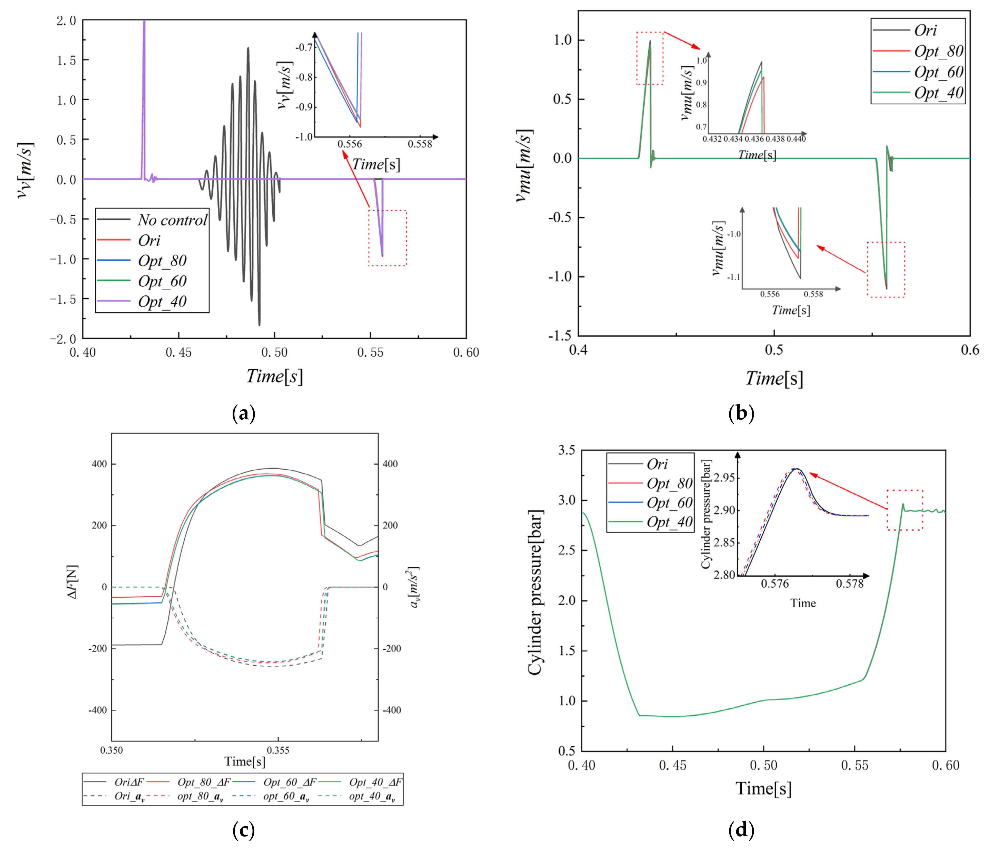
- Figure 13a,b show the valve plate and unloader speeds, respectively. The unloader of the control system not only reduced the valve plate withdrawal speed but also suppressed the vibration of the valve plate, thus reducing the fatigue damage and impact damage of the valve plate.
- (2)
- The valve plate withdrawal speed decreased with the different optimization parameters. The 60% and 40% loads decreased by almost the same amount and were greater than the 80% load. Similarly, the unloader ejection and withdrawal speeds exhibited the same downward trend.
- (3)
- The change in the movement characteristics of the valve plate caused changes in other flow characteristics, which subsequently changed the thermodynamic parameters of the compressor. As the speed decreased, the system moved into an advanced state; Figure 13d shows that the compression and exhaust processes occurred earlier, resulting in increases in both the adjustment displacement error and work deviation. However, owing to the small proportion of lead time, the deviation was small and the values were less than 5%.
- (1)
- Because the stiffness of the reset spring decreased by a small proportion of the optimization parameters, the reset spring force was basically the same as the initial spring force, indicating that the power source was basically the same.
- (2)
- The inlet pressure decreased significantly, resulting in a low initial hydraulic pressure. Additionally, the hydraulic oil outflow speed was slow, owing to the backpressure, which indicated that the initial resistance source was low, and the descent rate was slow. Together, the initial acceleration of the unloader withdrawal under the optimized parameters was large and well-advanced. However, the maximum acceleration was less than the initial parameter acceleration (Figure 13c), which also resulted in a more substantial and earlier start of the unloader withdrawal speed. However, the final speed was less than the initial parameter, and the disc withdrawal was controlled by the unloader for the same reason.
4.3. Verification of Experimental Results
5. Conclusions
- (1)
- Based on the multi-system simulation model of the flow control system, the DOE test was performed using the optimal Latin hypercubic sampling technology. Based on the test data, we observed no apparent interaction between the three key parameters for the unloader ejection speed, indicating that the three parameters were independent of each other, but for the withdrawal speed, the spring stiffness interacted with the oil inlet and oil return pressures. The degree of interaction between the two differed depending on the load.
- (2)
- The suction valve was the coupling point between the mechanical and gas systems. The change in its motion characteristics directly changed the flow characteristics and thermodynamic properties of the gas in the cylinder. As valve plate withdrawal was controlled by the unloader, the decrease in the unloader withdrawal speed resulted in an increase in the performance bias of the control system, which became more sensitive to the decrease in speed as the load decreased. A low load deviation increased at similar speeds.
- (3)
- Based on the principle of maximum speed decrease ratio and minimum deviation, the optimum values of three key parameters were finally determined, i.e., the intake pressure was 62 bar, the return pressure was 12 bar, and the reset spring stiffness was 74,715 N/m. Via simulation experiments, we observed that relative to the initial design, the maximum reduction ratio of the unloader ejection and withdrawal speeds was more than 5%, the valve plate withdrawal speed decreased to approximately 3%, relative to the free withdrawal of the valve disc, and the reduction ratio of the speed was more than 50%, whereas the performance deviation of the control system was less than <5%.
- (4)
- The experimental results demonstrated that the flow control system operated under the optimized key parameters, the impact energy of the unloader ejection and withdrawal significantly decreased, and the deviation of the regulation performance parameters was small. Therefore, after parameter optimization, the service life of the mechanical system in the flow control system was extended, the overall performance of the system improved, and the energy consumption and cost were reduced.
Author Contributions
Funding
Institutional Review Board Statement
Informed Consent Statement
Data Availability Statement
Conflicts of Interest
Nomenclature
| area (m2) | |
| flow displacement deviation | |
| gas work deviation | |
| volume elastic modulus of the hydraulic fluid (Pa) | |
| force (N) | |
| gravity (N) | |
| spring stiffness (N/m) | |
| mass (kg) | |
| total number of data points | |
| quantity of heat (J) | |
| gas constant | |
| scale factor. | |
| temperature (°C) | |
| cycle period (s) | |
| average temperature (°C) | |
| proxy function | |
| simplified proxy function | |
| volume (m3) | |
| weight coefficient | |
| target variable | |
| number of valve springs | |
| variable | |
| proxy function coefficient | |
| specific heat capacity at constant volume (J/(kg°C)) | |
| specific heat capacity at constant pressure (J/(kg°C)) | |
| friction (N) | |
| acceleration of gravity (m2/s) | |
| enthalpy unit (J/kg) | |
| adiabatic index | |
| gas mass (kg) | |
| pressure (pa) | |
| flow (m3/s) | |
| time (s) | |
| u | internal energy unit (J/kg) |
| w | approximate function |
| displacement (m) | |
| speed (m/s) | |
| Greek | |
| installation angle of unloader | |
| effective flow area (m2) | |
| interaction coefficient | |
| heat transfer coefficient | |
| coefficient of applied force of gas | |
| relative position coefficient | |
| state coefficient | |
| change quantity | |
| load coefficient | |
| Subscripts | |
| oil return | |
| cylinder | |
| experimental data | |
| effective flow area of air valve | |
| gas chamber | |
| hydraulic piston | |
| hydraulic pressure | |
| the ith data point | |
| oil inlet | |
| the jth data point | |
| cylinder head | |
| load | |
| residual force of mechanical unloader | |
| mechanical unloader | |
| initial value of mechanical unloader | |
| piston | |
| hydraulic oil | |
| pump | |
| cylinder wall | |
| oil inlet relief valve | |
| oil return relief valve | |
| return spring | |
| suction process | |
| simulation data | |
| valve | |
| initial value of valve | |
| stress surface of valve plate | |
| residual force of valve plate | |
| Superscript | |
| ejection process | |
| reset process | |
| optimized value before reset | |
Appendix A

| Object Function | |||||||
|---|---|---|---|---|---|---|---|
| Term | Coefficent | Term | Coefficent | Term | Coefficent | Term | Coefficent |
| −1.93 × 10⁻² | −1.60 × 10⁻³ | −4.61 × 10⁻¹ | 1.25 × 10 | ||||
| −2.50 × 10⁻³ | 1.02 × 10⁻⁶ | −1.25 × 10⁻⁵ | −1.13 × 10⁻⁵ | ||||
| 4.32 × 10⁻⁴ | −9.97 × 10⁻⁴ | 2.66 × 10⁻² | 3.25 × 10⁻² | ||||
| 7.21 × 10⁻⁹ | −1.29 × 10⁻³ | 5.77 × 10⁻⁴ | 5.78 × 10⁻⁵ | ||||
| 2.57 × 10⁻⁸ | −9.04 × 10⁻¹² | 7.88 × 10⁻⁸ | −4.51 × 10⁻³ | ||||
| −7.55 × 10⁻⁵ | 1.06 × 10⁻⁵ | −2.32 × 10⁻⁷ | 3.54 × 10⁻⁸ | ||||
| −6.20 × 10⁻¹⁰ | 8.93 × 10⁻⁹ | −1.30 × 10⁻⁴ | 4.00 × 10⁻⁴ | ||||
| 3.58 × 10⁻⁶ | 1.25 × 10⁻⁸ | −1.41 × 10⁻⁹ | −1.39 × 10⁻⁵ | ||||
| Object Function | |||||||
|---|---|---|---|---|---|---|---|
| Term | Term | Term | Term | Term | Term | Term | Term |
| −1.26 × 10 | −2.78 × 10⁻³ | −5.10 × 10⁻¹ | 7.52 × 10⁻¹ | ||||
| 7.97 × 10⁻⁵ | 1.81 × 10⁻⁶ | −1.30 × 10⁻⁵ | −1.08 × 10⁻⁵ | ||||
| −1.04 × 10⁻³ | −1.80 × 10⁻³ | 2.66 × 10⁻² | 1.50 × 10⁻² | ||||
| −1.87 × 10⁻⁹ | −2.68 × 10⁻³ | 8.74 × 10⁻⁸ | 1.47 × 10⁻² | ||||
| 1.87 × 10⁻⁸ | −1.46 × 10⁻¹¹ | −1.68 × 10⁻⁷ | −5.84 × 10⁻⁵ | ||||
| −3.05 × 10⁻⁵ | 3.95 × 10⁻⁵ | −1.10 × 10⁻⁴ | −5.10 × 10⁻⁴ | ||||
| 1.97 × 10⁻¹⁴ | 1.47 × 10⁻⁸ | −2.11 × 10⁻⁷ | 5.38 × 10⁻⁸ | ||||
| −7.83 × 10⁻²⁰ | 2.25 × 10⁻⁸ | 1.05 × 10⁻⁶ | −1.57 × 10⁻²¹ | ||||
| Object Function | |||||||
|---|---|---|---|---|---|---|---|
| Term | Coefficent | Term | Coefficent | Term | Coefficent | Term | Coefficent |
| 4.19 × 10⁻¹ | −5.25 × 10⁻³ | −7.06 × 10⁻¹ | 7.75 × 10⁻¹ | ||||
| −5.47 × 10⁻⁴ | 1.93 × 10⁻⁶ | 2.26 × 10⁻² | −1.03 × 10⁻⁵ | ||||
| 3.46 × 10⁻⁸ | −1.82 × 10⁻³ | −2.08 × 10⁻¹⁰ | 1.36 × 10⁻² | ||||
| 2.52 × 10⁻⁸ | −2.68 × 10⁻³ | −1.64 × 10⁻⁵ | 1.55 × 10⁻² | ||||
| −3.67 × 10⁻⁵ | −1.56 × 10⁻¹¹ | 6.30 × 10⁻⁸ | −4.48 × 10⁻⁵ | ||||
| 9.54 × 10⁻⁶ | 3.99 × 10⁻⁵ | −2.38 × 10⁻⁷ | −5.59 × 10⁻⁴ | ||||
| −8.75 × 10⁻²² | 1.49 × 10⁻⁸ | 1.27 × 10⁻¹⁵ | 4.94 × 10⁻⁸ | ||||
| −4.86 × 10⁻⁸ | 2.19 × 10⁻⁸ | 1.46 × 10⁻⁶ | −1.70 × 10⁻²¹ | ||||
| Object Function | |||||||
|---|---|---|---|---|---|---|---|
| Term | Coefficent | Term | Coefficent | Term | Coefficent | Term | Coefficent |
| −3.72 × 10⁻¹ | 4.30 × 10⁻³ | −7.96 × 10⁻¹ | 7.57 × 10⁻¹ | ||||
| 2.22 × 10⁻⁵ | 2.38 × 10⁻⁶ | 2.67 × 10⁻² | −1.07 × 10⁻⁵ | ||||
| −4.66 × 10⁻³ | −2.53 × 10⁻³ | −1.36 × 10⁻¹⁰ | 1.45 × 10⁻² | ||||
| −3.28 × 10⁻¹⁰ | −3.18 × 10⁻³ | 5.09 × 10⁻⁸ | 1.55 × 10⁻² | ||||
| 5.01 × 10⁻⁸ | −2.09 × 10⁻¹¹ | −2.17 × 10⁻⁷ | −5.07 × 10⁻⁵ | ||||
| 1.57 × 10⁻⁸ | 5.15 × 10⁻⁵ | −1.06 × 10⁻⁴ | −5.39 × 10⁻⁴ | ||||
| −3.91 × 10⁻⁵ | 2.18 × 10⁻⁸ | 6.75 × 10⁻²¹ | 4.83 × 10⁻⁸ | ||||
| 1.49 × 10⁻¹⁵ | 2.53 × 10⁻⁸ | 1.71 × 10⁻⁶ | −1.37 × 10⁻²¹ | ||||
| Object Function | |||||||
|---|---|---|---|---|---|---|---|
| Term | Coefficent | Term | Coefficent | Term | Coefficent | Term | Coefficent |
| −5.08 × 10⁻² | 3.21 × 10⁻³ | −8.72 × 10⁻¹ | 7.77 × 10⁻¹ | ||||
| 4.89 × 10⁻⁶ | 2.52 × 10⁻⁶ | 2.55 × 10⁻² | −1.06 × 10⁻⁵ | ||||
| −4.30 × 10⁻³ | −2.64 × 10⁻³ | −1.31 × 10⁻³ | 1.40 × 10⁻² | ||||
| −3.90 × 10⁻¹¹ | −3.49 × 10⁻³ | 4.07 × 10⁻⁸ | 1.53 × 10⁻² | ||||
| 6.59 × 10⁻⁴ | −2.07 × 10⁻¹¹ | −2.27 × 10⁻⁷ | −4.53 × 10⁻⁵ | ||||
| 4.08 × 10⁻⁸ | 6.38 × 10⁻⁵ | −2.66 × 10⁻¹⁵ | −5.30 × 10⁻⁴ | ||||
| −9.61 × 10⁻⁵ | 2.16 × 10⁻⁸ | 9.30 × 10⁻⁵ | 4.51 × 10⁻⁸ | ||||
| −2.09 × 10⁻⁶ | 2.64 × 10⁻⁸ | 2.20 × 10⁻²⁰ | −1.24 × 10⁻²¹ | ||||
| Object Function | |||||||
|---|---|---|---|---|---|---|---|
| Term | Coefficent | Term | Coefficent | Term | Coefficent | Term | Coefficent |
| −2.93 × 10⁻¹ | 2.30 × 10⁻² | −8.90 × 10⁻¹ | 9.13 × 10⁻¹ | ||||
| 1.27 × 10⁻⁵ | 3.43 × 10⁻⁶ | 2.51 × 10⁻² | −1.06 × 10⁻⁵ | ||||
| −6.73 × 10⁻³ | −4.10 × 10⁻³ | −1.65 × 10⁻³ | 9.25 × 10⁻³ | ||||
| −1.24 × 10⁻¹⁰ | −5.08 × 10⁻³ | 4.58 × 10⁻⁸ | 1.46 × 10⁻² | ||||
| 1.12 × 10⁻⁷ | −3.06 × 10⁻¹¹ | −1.98 × 10⁻⁷ | −4.76 × 10⁻⁴ | ||||
| 1.31 × 10⁻⁷ | 8.73 × 10⁻⁵ | −2.81 × 10⁻¹⁵ | 5.05 × 10⁻⁸ | ||||
| −1.76 × 10⁻⁴ | 3.51 × 10⁻⁸ | 1.10 × 10⁻⁴ | −1.39 × 10⁻¹⁶ | ||||
| −2.69 × 10⁻⁹ | 3.99 × 10⁻⁸ | 2.32 × 10⁻²⁰ | −1.41 × 10⁻⁹ | ||||
References
- Aprea, C.; Renno, C. Experimental Model of a Variable Capacity Compressor. Int. J. Energy Res. 2009, 33, 23–40. [Google Scholar] [CrossRef]
- Li, D.; Wu, H.; Gao, J. Experimental Study on Stepless Capacity Regulation for Reciprocating Compressor Based on Novel Rotary Control Valve. Int. J. Refrig. 2013, 36, 1701–1715. [Google Scholar] [CrossRef]
- Li, M.L.; Zhao, G.Y.; Hong, W.R.; Chen, B.; Cao, J.L. Valve Plate Roll Analysis on Stepless Capacity Regulation for Reciprocating Compressor. Compress. Technol. 2013, 1, 14–16. (In Chinese) [Google Scholar]
- Pichler, K.; Lughofer, E.; Pichler, M.; Buchegger, T.; Klement, E.P.; Huschenbett, M. Fault Detection in Reciprocating Compressor Valves under Varying Load Conditions. Mech. Syst. Signal Process. 2016, 70–71, 104–119. [Google Scholar] [CrossRef]
- Tang, B.; Zhao, Y.; Li, L.; Wang, L.; Liu, G.; Yang, Q.; Xu, H.; Zhu, F.; Meng, W. Dynamic Characteristics of Suction Valves for Reciprocating Compressor with Stepless Capacity Control System. Proc. Inst. Mech. Eng. Part E J. Process Mech. Eng. 2014, 228, 104–114. [Google Scholar] [CrossRef]
- Hong, W.; Jin, J.; Wu, R.; Zhang, B. Theoretical Analysis and Realization of Stepless Capacity Regulation for Reciprocating Compressors. Proc. Inst. Mech. Eng. Part E J. Process Mech. Eng. 2009, 223, 205–213. [Google Scholar] [CrossRef]
- Jin, J.; Hong, W.; Wu, R. Valve Dynamic Characteristic and Stress Analysis of Reciprocating Compressor Under Stepless Capacity Regulation. J. Fluid Mech. 2009, 415–420. [Google Scholar] [CrossRef]
- Wang, Y.; Zhang, J.; Jiang, Z.; Zhou, C.; Liu, W. Investigation on Thermodynamic State and Valve Dynamics of Reciprocating Compressors with Capacity Regulation System and Parameter Optimization. Eng. Appl. Comput. Fluid Mech. 2019, 13, 923–937. [Google Scholar] [CrossRef]
- Zhang, J.; Zhou, C.; Jiang, Z.; Wang, Y.; Sun, X. Optimization Design of Actuator Parameters with Stepless Capacity Control System Considering the Effect of Backflow Clearance. Appl. Sci. 2020, 10, 2703. [Google Scholar] [CrossRef]
- Liu, G.; Zhao, Y.; Tang, B.; Li, L. Dynamic Performance of Suction Valve in Stepless Capacity Regulation System for Large-Scale Reciprocating Compressor. Appl. Therm. Eng. 2016, 96, 167–177. [Google Scholar] [CrossRef]
- Wang, Y.; Jiang, Z.; Zhang, J.; Zhou, C.; Liu, W. Performance Analysis and Optimization of Reciprocating Compressor with Stepless Capacity Control System under Variable Load Conditions. Int. J. Refrig. 2018, 94, 174–185. [Google Scholar] [CrossRef]
- Zhang, J.; Wang, Y.; Li, X.; Jiang, Z.; Xie, Y.; Zhu, Q. A Simulation Study on the Transient Motion of a Reciprocating Compressor Suction Valve Under Complicated Conditions. J. Fail. Anal. Prev. 2016, 16, 790–802. [Google Scholar] [CrossRef]
- Xiuqing, Y.; Minzhou, L.; Tao, M.; Damao, Y. Co-Simulation Research of the Mechanical-Hydraulic-Control Coupling System of ITER Tractor. Plasma Sci. Technol. 2009, 11, 334–340. [Google Scholar] [CrossRef]
- Ma, J.G.; Wu, Z.Z.; Guo, H.R.; Li, J. Design and Simulation Study of a Certain Landing Gear Loading Simulation System. Adv. Mat. Res. 2014, 871, 69–76. [Google Scholar] [CrossRef]
- Trikande, M.W.; Jagirdar, V.V.; Rajamohan, V.; Sampat Rao, P.R. Investigation on Semi-Active Suspension System for Multi-Axle Armoured Vehicle Using Co-Simulation. Def. Sci. J. 2017, 67, 269–275. [Google Scholar] [CrossRef][Green Version]
- Zeng, Q.; Gao, K.; Zhang, H.; Jiang, S.; Jiang, K. Vibration Analysis of Shearer Cutting System Using Mechanical Hydraulic Collaboration Simulation. Proc. Inst. Mech. Eng. Part K J. Multi Body Dyn. 2017, 231, 708–725. [Google Scholar] [CrossRef]
- Spiryagin, M.; Simson, S.; Cole, C.; Persson, I. Co-Simulation of a Mechatronic System Using Gensys and Simulink. Veh. Syst. Dyn. 2012, 50, 495–507. [Google Scholar] [CrossRef]
- Zhou, L.; Yan, G.; Ou, J. Response Surface Method Based on Radial Basis Functions for Modeling Large-Scale Structures in Model Updating. Comput. Aided Civ. Infrastruct. Eng. 2013, 28, 210–226. [Google Scholar] [CrossRef]
- Ezhilsabareesh, K.; Rhee, S.H.; Samad, A. Shape Optimization of a Bidirectional Impulse Turbine via Surrogate Models. Eng. Appl. Comput. Fluid Mech. 2018, 12, 1–12. [Google Scholar] [CrossRef]
- Han, H.; Yu, R.; Li, B.; Zhang, Y.; Wang, W.; Chen, X. Multi-Objective Optimization of Corrugated Tube with Loose-Fit Twisted Tape Using RSM and NSGA-II. Int. J. Heat Mass Transf. 2019, 131, 781–794. [Google Scholar] [CrossRef]
- He, Q.; Ma, D.; Zhang, Z.; Yao, L. Mean Compressive Stress Constitutive Equation and Crashworthiness Optimization Design of Three Novel Honeycombs under Axial Compression. Int. J. Mech. Sci. 2015, 99, 274–287. [Google Scholar] [CrossRef]
- Yaghoobi, H.; Taheri, F. Analytical Solution and Statistical Analysis of Buckling Capacity of Sandwich Plates with Uniform and Non-Uniform Porous Core Reinforced with Graphene Nanoplatelets. Compos. Struct. 2020, 252, 112700. [Google Scholar] [CrossRef]
- Song, T.; Yao, Y.; Ni, L. Response Surface Method to Study the Effect of Conical Surface and Vortex-Finder Lengths on de-Foulant Hydrocyclone with Reflux Ejector. Sep. Purif. Technol. 2020, 253, 117511. [Google Scholar] [CrossRef]
- Chiandussi, G.; Codegone, M.; Ferrero, S.; Varesio, F.E. Comparison of multi-objective optimization methodologies for engineering applications. Comput. Math. Appl. 2012, 63, 912–942. [Google Scholar] [CrossRef]
- Li, H.; Zhang, Q. Multiobjective Optimization Problems with Complicated Pareto Sets, MOEA/D and NSGA-II. IEEE Trans. Evol. Comput. 2009, 13, 284–302. [Google Scholar] [CrossRef]
- Mostaghim, S.; Teich, J. Strategies for Finding Good Local Guides in Multi-Objective Particle Swarm Optimization (MOPSO). IEEE Lat. Am. Trans. 2003, 2, 26–33. [Google Scholar] [CrossRef]
- Yang, X.S.; Karamanoglu, M.; He, X. Flower Pollination Algorithm: A Novel Approach for Multiobjective Optimization. Eng. Optim. 2014, 46, 1222–1237. [Google Scholar] [CrossRef]
- Mirjalili, S.; Saremi, S.; Mirjalili, S.M.; Coelho, L.D.S. Multi-Objective Grey Wolf Optimizer: A Novel Algorithm for Multi-Criterion Optimization. Expert Syst. Appl. 2016, 47, 106–119. [Google Scholar] [CrossRef]
- Wu, K.A.; Yan, X.H.; Chen, Z.X. Hybrid multi-objective evolutionary algorithm based on Pareto sort. Comput. Eng. Appl. 2015, 51, 62–68. (In Chinese) [Google Scholar]
- Yang, Y.; Liu, J.; Tan, S.; Wang, H. Application of Constrained Multi-Objective Evolutionary Algorithm in Multi-Source Compressed-Air Pipeline Optimization Problems. IFAC-PapersOnLine 2018, 51, 168–173. [Google Scholar] [CrossRef]
- Zhang, L.; Chen, L.; Xia, S.; Ge, Y.; Wang, C.; Feng, H. Multi-Objective Optimization for Helium-Heated Reverse Water Gas Shift Reactor by Using NSGA-II. Int. J. Heat Mass Transf. 2020, 148, 119025. [Google Scholar] [CrossRef]
- Demissie, A.; Zhu, W.; Belachew, C.T. A multi-objective optimization model for gas pipeline operations. Comput. Chem. Eng. 2017, 100, 94–103. [Google Scholar] [CrossRef]
- Jiang, J.; Cai, H.; Ma, C.; Qian, Z.; Chen, K.; Wu, P. A Ship Propeller Design Methodology of Multi-Objective Optimization Considering Fluid–Structure Interaction. Eng. Appl. Comput. Fluid Mech. 2018, 12, 28–40. [Google Scholar] [CrossRef]
- Horn, J.; Nafpliotis, N.; Goldberg, D.E. A niched Pareto genetic algorithm for multiobjective optimization. Proceedings of the First IEEE Conference on Evolutionary Computation. IEEE World Congr. Comput. Intell. 1994, 82–87. [Google Scholar] [CrossRef]
- Zitzler, E.; Thiele, L. Multiobjective evolutionary algorithms: A comparative case study and the strength Pareto approach. IEEE Trans. Evol. Comput. 1999, 3, 257–271. [Google Scholar] [CrossRef]
- Shu, Y.; Yong, S.; Chang, Q. Performance Assessment and Optimal Design of Hybrid Material Bumper for Pedestrian Lower Extremity Protection. Int. J. Mech. Sci. 2020, 165, 105210. [Google Scholar] [CrossRef]
- Cui, Y.; Geng, Z.; Zhu, Q.; Han, Y. Review: Multi-objective optimization methods and application in energy saving. Energy 2017, 125, 681–704. [Google Scholar] [CrossRef]
- Liu, C.B.; Bu, W.Y.; Dong, X. Multi-objective shape optimization of a plate-fin heat exchanger using cfd and multi-objective genetic algorithm. Int. J. Heat Mass Transf. 2017, 111, 65–82. [Google Scholar] [CrossRef]
- Jiang, Z.N.; Zhou, C.; Wang, Y.; Zhang, J.J.; Sun, X. Optimization design of actuator parameters in multistage reciprocating compressor stepless capacity control system based on NSGA-II. Math. Probl. Eng. 2020, 2020, 7581845. [Google Scholar] [CrossRef]
- Gao, Q.H.; Wang, S.A.; Huang, X.F. Model Library Build for Hydraulic System Simulation with SIMULINK. Syst. Simul. Technol. Appl. 2006, 8, 317–320. (In Chinese) [Google Scholar]
- Armaghani, T.; Sahebi, S.; Goodarzian, H. The first law simulation and second law analysis of a typical reciprocating air compressor. Indian J. Sci. Technol. 2012, 5, 2390–2395. [Google Scholar] [CrossRef]
- Mamedov, B.A.; Somuncu, E.; Askerov, I.M. Theoretical Assessment of Compressibility Factor of Gases by Using Second Virial Coefficient, Zeitschrift Fur Naturforsch. Sect. A J. Phys. Sci. 2018, 73, 121–125. [Google Scholar] [CrossRef]
- Jin, J.M.; Hong, W.R. Valve dynamic and thermal cycle model in stepless capacity regulation for reciprocating compressor. Chin. J. Mech. Eng. 2012, 25, 1151–1160. [Google Scholar] [CrossRef]
- Srinivas, N.; Deb, K. Muiltiobjective Optimization Using Nondominated Sorting in Genetic Algorithms. Evol. Comput. 1994, 2, 221–248. [Google Scholar] [CrossRef]
- Deb, K.; Pratap, A.; Agarwal, S.; Meyarivan, T. A fast and elitist multiobjective genetic algorithm: NSGA-II. IEEE Trans. Evol. Comput. 2002, 6, 182–197. [Google Scholar] [CrossRef]


| Item | Value |
|---|---|
| Suction pressure (MPa) | 0.1 |
| Discharge pressure (MPa) | 0.3 |
| Rotating speed (rpm) | 300 |
| Valve lift (mm) | 2 |
| Inlet pressure (MPa) | 8 |
| Oil return pressure (MPa) | 0 |
| Return spring stiffness (N/m) | 80,000 |
| Load | Evaluation Index | Objective Function | |||
|---|---|---|---|---|---|
| 90 | 0.933 | 0.999 | 0.997 | 0.999 | |
| 0.918 | 0.999 | 0.997 | 0.999 | ||
| 80 | 0.965 | 0.999 | 0.995 | 0.999 | |
| 0.957 | 0.999 | 0.994 | 0.999 | ||
| 70 | 0.969 | 0.999 | 0.995 | 0.999 | |
| 0.963 | 0.999 | 0.994 | 0.998 | ||
| 60 | 0.984 | 0.998 | 0.997 | 0.999 | |
| 0.979 | 0.998 | 0.996 | 0.999 | ||
| 50 | 0.988 | 0.998 | 0.996 | 0.999 | |
| 0.985 | 0.997 | 0.995 | 0.998 | ||
| 40 | 0.982 | 0.998 | 0.997 | 0.999 | |
| 0.976 | 0.997 | 0.996 | 0.999 | ||
| 30 | 0.991 | 0.998 | 0.997 | 0.999 | |
| 0.988 | 0.997 | 0.996 | 0.998 | ||
| Object Function | |||||||
|---|---|---|---|---|---|---|---|
| Term | Coefficent | Term | Coefficent | Term | Coefficent | Term | Coefficent |
| −9.13 × 10⁻² | −1.12 × 10⁻² | −3.79 × 10⁻¹ | 9.75 × 10⁻¹ | ||||
| 1.89 × 10⁻⁶ | 1.47 × 10⁻⁶ | −1.54 × 10⁻⁵ | −1.06 × 10⁻⁵ | ||||
| −7.80 × 10⁻⁴ | −1.24 × 10⁻³ | 2.07 × 10⁻² | 8.35 × 10⁻³ | ||||
| −1.43 × 10⁻¹¹ | −1.02 × 10⁻³ | −4.68 × 10⁻⁵ | 1.36 × 10⁻² | ||||
| 8.02 × 10⁻⁵ | −1.20 × 10⁻¹¹ | 1.41 × 10⁻⁷ | −1.11 × 10⁻³ | ||||
| 1.31 × 10⁻⁸ | 1.07 × 10⁻⁸ | −6.09 × 10⁻⁸ | 2.52 × 10⁻⁸ | ||||
| −9.49 × 10⁻⁶ | 1.49 × 10⁻⁸ | −2.14 × 10⁻⁴ | 8.76 × 10⁻⁵ | ||||
| −1.03 × 10⁻⁷ | −5.69 × 10⁻⁶ | 2.09 × 10⁻⁶ | 2.28 × 10⁻⁶ | ||||
| Value Range | NSGA-II Parameter Setting | ||
|---|---|---|---|
| Name | Value | Name | Value |
| 46,000~80,000 | Population size | 60 | |
| 60~80 | Number of generations | 50 | |
| 0~12 | Crossover probability | 0.9 | |
| −10~10% | Crossover distribution index | 10 | |
| −10~10% | Mutation distribution index | 20 | |
| Load | |||||||
|---|---|---|---|---|---|---|---|
| 90% | 63,173~67,832 | 60~64 | 0~0.4 | −2~−4% | −2~−4% | −1.2~−1.5% | 0~0.2% |
| 80% | 63,019~66,276 | 60~62 | 0~0.2 | −4~−6% | −4~−6% | −0.2~0 | −0.2~0 |
| 70% | 74,421~76,589 | 60~61 | 10~12 | −6~−8% | −6~−7% | 0.8~1% | 0.2~0.4% |
| 60% | 74,630~77,144 | 60~62 | 10~12 | −6~−8% | −6~−8% | 0.5~0.2% | 0.3~0.4% |
| 50% | 63,134~64,276 | 60~61 | 0~0.4 | −6~−7% | −5~−6% | 0.3~4% | 0.2~0.4% |
| 40% | 65,012~69,182 | 60~62 | 0~3 | −6~−8% | −4~−6% | −0.7~0.3% | 0~0.3% |
| 30% | 62,451~66,912 | 60~62 | 0~3 | −5~−6% | −5~−6% | −0.5~0 | 0.3~0.5% |
| Design Variable | Weight Factor | Scale Factor | |
| 1 | 0.001 | ||
| 1 | 0.001 | ||
| 1 | 0.1 | ||
| 1 | 0.1 | ||
| Second optimization result | |||
| Load | (N/m) | (bar) | (bar) |
| 90% | 77,002 | 60 | 11 |
| 80% | 74,680 | 60 | 11 |
| 70% | 74,988 | 61 | 10 |
| 60% | 74,941 | 62 | 12 |
| 50% | 74,631 | 62 | 11 |
| 40% | 74,715 | 62 | 12 |
| 30% | 74,633 | 62 | 12 |
| Load | Evaluation Index | Test Project | ||||||
|---|---|---|---|---|---|---|---|---|
| Opt_90 | Opt_80 | Opt_70 | Opt_60 | Opt_50 | Opt_40 | Opt_30 | ||
| 90 | −4.39% | −2.16% | −1.58% | −0.29% | −1.27% | −1.28% | −1.42% | |
| −3.48% | −6.00% | −8.50% | −7.27% | −6.02% | −7.58% | −7.69% | ||
| −1.05% | −1.82% | −0.87% | −3.44% | −2.43% | −3.87% | −4.03% | ||
| −52.43% | −52.80% | −52.35% | −53.58% | −53.10% | −53.79% | −53.87% | ||
| 80 | −6.70% | −3.74% | −3.19% | −1.63% | −1.31% | −1.27% | −1.15% | |
| −2.70% | −4.01% | −2.83% | −5.49% | −4.40% | −5.78% | −5.89% | ||
| −0.11% | −2.49% | −1.66% | −3.90% | −2.97% | −4.33% | −4.48% | ||
| −51.28% | −52.44% | −52.04% | −53.13% | −52.68% | −53.34% | −53.41% | ||
| 70 | −9.30% | −6.48% | −5.62% | −3.44% | −3.88% | −3.10% | −2.97% | |
| −5.65% | −6.99% | −5.91% | −8.43% | −7.46% | −8.13% | −8.22% | ||
| −2.08% | −3.97% | −3.41% | −4.95% | −4.23% | −5.34% | −5.48% | ||
| −48.73% | −49.72% | −49.43% | −50.23% | −49.86% | −50.44% | −50.51% | ||
| 60 | −9.33% | −6.51% | −5.65% | −3.47% | −3.91% | −3.13% | −3.01% | |
| −4.98% | −7.06% | −5.98% | −8.51% | −7.54% | −8.77% | −8.87% | ||
| −2.23% | −4.11% | −3.56% | −5.09% | −4.38% | −5.49% | −5.63% | ||
| −48.59% | −49.58% | −49.29% | −50.10% | −49.73% | −50.31% | −50.38% | ||
| 50 | −10.04% | −6.92% | −6.05% | −3.88% | −4.30% | −3.54% | −3.41% | |
| −2.54% | −4.57% | −3.62% | −6.05% | −5.15% | −6.30% | −6.40% | ||
| −0.24% | −2.00% | −1.60% | −2.93% | −2.30% | −3.32% | −3.46% | ||
| −47.84% | −48.75% | −48.55% | −49.24% | −48.91% | −49.44% | −49.52% | ||
| 40 | −9.75% | −6.94% | −6.06% | −3.89% | −4.32% | −3.55% | −3.43% | |
| −2.23% | −4.22% | −3.31% | −5.68% | −4.81% | −5.93% | −6.03% | ||
| −0.07% | −1.61% | −1.26% | −2.49% | −1.90% | −2.88% | −3.02% | ||
| −47.25% | −48.14% | −47.95% | −48.60% | −48.29% | −48.81% | −48.88% | ||
| 30 | −9.76% | −6.96% | −6.08% | −3.91% | −4.34% | −3.57% | −3.45% | |
| −3.27% | −3.56% | −2.76% | −4.96% | −4.17% | −5.20% | −5.29% | ||
| −3.31% | −2.56% | −2.35% | −3.28% | −2.78% | −3.65% | −3.79% | ||
| −47.72% | −47.31% | −47.20% | −47.70% | −47.43% | −47.90% | −47.98% | ||
Publisher’s Note: MDPI stays neutral with regard to jurisdictional claims in published maps and institutional affiliations. |
© 2022 by the authors. Licensee MDPI, Basel, Switzerland. This article is an open access article distributed under the terms and conditions of the Creative Commons Attribution (CC BY) license (https://creativecommons.org/licenses/by/4.0/).
Share and Cite
Sun, X.; Wang, Y.; Zhang, J.; Lei, F.; Zhao, D.; Hong, H. Multi-Objective Optimization Design of Key Parameters of a Stepless Flow Control System with Multi-System Coupling Characteristics. Appl. Sci. 2022, 12, 1301. https://doi.org/10.3390/app12031301
Sun X, Wang Y, Zhang J, Lei F, Zhao D, Hong H. Multi-Objective Optimization Design of Key Parameters of a Stepless Flow Control System with Multi-System Coupling Characteristics. Applied Sciences. 2022; 12(3):1301. https://doi.org/10.3390/app12031301
Chicago/Turabian StyleSun, Xu, Yao Wang, Jinjie Zhang, Fuchang Lei, Degeng Zhao, and Huaibin Hong. 2022. "Multi-Objective Optimization Design of Key Parameters of a Stepless Flow Control System with Multi-System Coupling Characteristics" Applied Sciences 12, no. 3: 1301. https://doi.org/10.3390/app12031301
APA StyleSun, X., Wang, Y., Zhang, J., Lei, F., Zhao, D., & Hong, H. (2022). Multi-Objective Optimization Design of Key Parameters of a Stepless Flow Control System with Multi-System Coupling Characteristics. Applied Sciences, 12(3), 1301. https://doi.org/10.3390/app12031301