Article

Multiple-Valued Logic Modelling for Agents Controlled via Optical Networks

by
Alexey Yu. Bykovsky
P.N. Lebedev Physical Institute RAS, Leninsky pr. 53, 119991 Moscow, Russia
Appl. Sci. 2022, 12(3), 1263; https://doi.org/10.3390/app12031263
Submission received: 30 November 2021 / Revised: 14 January 2022 / Accepted: 17 January 2022 / Published: 25 January 2022
(This article belongs to the Collection New Trends in Optical Networks)

Abstract

:
The methods of data verification are discussed, which are intended for the distant control of autonomous mobile robotic agents via networks, combining optical data links. The problem of trust servers is considered for position verification and position-based cryptography tasks. In order to obtain flexible quantum and classical verification procedures, one should use the collective interaction of agents and network nodes, including some elements of the blockchain. Multiple-valued logic functions defined within discrete k-valued Allen–Givone algebra are proposed for the logically linked list of entries and the distributed ledger, which can be used for distant data verification and breakdown restoration in mobile agents with the help of partner network nodes. A distributed ledger scheme involves the assigning by distant partners of random hash values, which further can be used as keys for access to a set of distributed data storages, containing verification and restoration data. Multiple-valued logic procedures are simple and clear enough for high-dimensional logic modelling and for the design of combined quantum and classical protocols.

Graphical Abstract

1. Introduction

1.1. Data Protection Problem of Network Robotics

Modern fiber optics networks have become the base for high throughput communication networks combining 5/6G Internet [1,2], big data services [3], quantum key distribution (QKD) lines [4,5], and futuristic quantum computing systems [6]. However, now they are also a good candidate for the massive distant control of autonomous robotic devices, which involves the Internet of unmanned transport vehicles (IoV) [7], industrial systems [8], medicine nursing robots [9], the Internet of Things (IoT) [10], and smart cities [11], supported by mechatronics drives reproducing human movements [12] and computer vision systems [13,14]. Such autonomous robots are planned to be used as separate devices [15] in a collective of collaborating agents commonly called the multiagent system (MAS) [16] or in a global network-centric system [17]. All such designs are based on methods of artificial intelligence (AI), which is the method of imitating the individual and collective work of people [15]. As mobile robotic agents need wireless data links, communication networks should combine fiber optics lines and wired Ethernet pairs with wireless Wi-Fi, Bluetooth, and atmospheric satellite or terrestrial laser lines [4,5,18] (see Figure 1). Modern smartphones [19] supporting AI algorithms can also be used for the distant control of robots.
Thus, modern networks add many new participants of network data exchange and enlarge the number of possible hardware and software platforms for the interaction of robotic agents with distant users. The modelling of such systems becomes very complicated as, besides network communications, it should describe human decision making and collective work procedures [15]. The limiting factor for network robotics is the data protection problem, as modern networks and especially their wireless components cannot provide the necessary level of protection from attacks and data leakages [20,21]. Quantum key distribution systems [4,5,18,22,23] partially improve the situation, but even they do not exclude specific quantum attacks and malicious impacts on supporting classical components. Unfortunately, data leakages due to disloyal personnel have become more of an actual problem than computer viruses and attacks aimed at stationary network nodes [23]. Furthermore, distant mobile robotic agents have many additional vulnerabilities, as current computer vision and decision-making systems [14,15] cannot replace human monitoring. At the same time, mass and unexpensive network robotics need to avoid trusted network nodes, exploiting the special design of servers and intense human control [24,25] that are mainly appropriate for large corporative systems.
In order to enhance the security level for the distant control of autonomous agents and MASs, it is necessary to combine quantum and traditional data protection methods with new AI algorithms, which now are grounded in concepts of agent and MASs [7,8,9,10,11,15,26,27,28]. The presented paper is devoted to the original properties of multiple-valued logic (MVL) [29], which provides the possibility to design new schemes of agents based on multiparametrical logic functions and easily provides the modelling of various procedures in a high-dimensional space of parameters [30]. MVL functions can also realize schemes of secret data coding for one-time cipher pads and random keys [31], to accumulate random data into the scheme of random oracle [32], to model the theoretically proven and most protected position-based cryptography protocol by D. Unruh [33], and to realize data classification procedures [30].
That is why the actual task of secured distant work of robotic agents and MASs [34] is the potential field of applications for MVL functions [29,30], which now needs the integration of disparate algorithms and schemes into the whole data-protection agent, combining quantum and classical data coding methods. The present paper discusses the design of “indestructible” and easy-for-verification MVL data structures, which adapt some blockchain schemes [35,36,37,38,39] for collective data verification by means of collective interaction of the agent with loyal network nodes without trusted servers.

1.2. Basic Properties of Agents

The concept of agents and MASs is one of the basic models in modern AI [15,22] and, in general, supports a large set of properties that hardware and software systems should possess for the efficient imitation of human abilities. Purely software agents are now called bots and are being successfully used in Internet data searches and creative activity [26,27], stock trading [28], and cryptocurrencies mining [35,36]. However, the realization of hardware robotic agents is a much more difficult task, as it is necessary to simultaneously control many subsystems [34,40,41]. In general, the model of the universal agent should possess dozens of properties [15,34,36,41,42,43], which should include at least:
  • autonomous activity and self-sustained decision making;
  • reactivity to external media and adaptive correction of behavior;
  • active impact on the external media, motivated by understanding of the scene;
  • interaction with other objects based on goals, desires, collaboration, and trust;
  • communicative abilities, including secured data exchange and storage;
  • flexible planning of activity and self-analysis of goals, tasks, and resources;
  • responsibility to the team, following to general aims and collaboration rules.
Modern MASs can deal with stationary and mobile agents, where stationary ones are mainly represented by software bots for information services [26,27,28,36] and hardware metering devices for power grid control [37,38,39]. Initially, the term “mobile agent” was used for software designs capable of expanding their activity from one platform to another [44], but now it is often used for hardware robots for transport, industrial systems, medical surgery, and nursing [7,8,9]. However, all of them have unresolved issues with data protection.

1.3. Data Protection of Stationary Agents in Classical and Quantum Network Nodes

As a whole, data protection methods for agents and MASs are based on the same principles as any other network nodes, but the unsatisfactory level of modern communication networks [20,21] is reinforced by the complexity of robotic agents. The concept of a trusted network node (or server) and trust modelling [24,25,26] is actually for both schemes with QKD lines and for traditional data links. The basic idea of a trusted server is that all its subsystems are well-secured ones, including data storages, data channels, devices for the detection of data leakages, and systems for the monitoring of administrative processes. In any situation, data coming from a trusted node are considered as absolutely correct and reliable for every user, and typically trusted nodes are associated with the expensive networks of government organizations and big corporations, which maintain large security staff with adequate administrative procedures and human monitoring. However, even cloud services and big data centers [45,46] can be successfully attacked.
The modern interpretation of trust problems for agents dates back at least to the document published by the National Institute of Standards and Technologies of the USA (NIST) [44]. Most typical problems of illegal activity included unauthorized access and data disclosure or corruption. Main countermeasures [22,24,25,37,38,39,40,42,43] included such methods as the verification of path histories, proof carrying code, partial result encapsulation, mutual itinerary recording with optional replication or voting, execution tracing, environmental key generation, and computing with encrypted functions. Trusted modelling in MASs considers concepts of trust and reputation [47], as well as argumentation [48].
As the intrinsic idea of autonomous agents is their working without permanent human monitoring [15], then some verification procedures should be shifted onto other agents and partner network nodes. Illegal activity can then be revealed by other agents by means of the estimation of an inadequate agent’s behavior, contradicting the rules used by the majority of participants [37,38,39]. AI algorithms imitating the work of human experts for the coordination of node activity were designed for stock trading bots [28], systems of e-commerce, and e-business [35,36]. Efforts to raise the trust level were based on trust estimates carried out by neighboring agents [49,50].
The practical design of collectively secured agents was represented by the smart infrastructure of an energy power grid [37,38,39], using smart metering and control of phasor for devices suspected in illegal activity. Such systems have combined the collective interaction of metering devices and gateways, which have involved the blockchain (BC), data integrity control, and insider attack mitigation methods.
Respectively, the BC method [37,38,39,51,52] and cryptocurrencies mining [53,54] demonstrate quite useful schemes of collective network data protection. Ledger (or registry) schemes in the BC [37,38,39,53,54] are based on the principle of linked data lists and have become the popular trend in modern computer technologies. The main idea here is that the distributed ledger of linked entries [53,54] is supported by the decentralized consortium of users, whose integral voting guarantees the correctness of data. However, attempts to apply trust estimation to mobile robotic systems have led to the design of complicated deep-learning schemes based on pre-trained learning with supervisor and acceptance observation history [55].
As modern fiber optics lines have obtained impressive throughput parameters of 115 Tb/s for single-mode fiber and 10 Pb/s for multi-core fiber [56,57,58,59], they seem to be excellent platforms for the secured distant control of robotic agents. Although modern QKD systems did not obtain enough parameters for mass stream secret coding by the most secured one-time cipher pad (OTP) coding method and have some quantum and classical vulnerabilities of their optical and computer components, they are hoped to provide large additional technical, competence, and cost barriers for eavesdroppers [22,23,60]. The drawbacks of modern fiber optics QKD lines refer to the real limited length of quantum key transfer (less than 80–100 km), low fan-out coefficients, the possibility of physical damage of a QKD line, and the threat of being suppressed by intense optical noise. Current designs of quantum memory [61] are too far from practical needs, and modern QKD schemes cannot provide reliable data storage and exclude illegal modifications. Moreover, quantum networks together with ordinary ones can suffer from data leakages carried out by disloyal personnel [62]. Nevertheless, the research of QKD schemes continues, and in order to raise the security level of energy power systems [63], the trusted server with “star” architecture was combined with the large number of QKD lines. Other attempts [64,65] also aimed at the realization of trusted nodes by various quantum schemes. The possibility of using atmospheric quantum laser lines for agents was principally demonstrated by key distribution between ground stations and satellites [66,67], as well as by experiments with an airborne platform [68]. However, satellite QKD links can only be a partial solution for mobile agents, as data exchange sessions are scheduled by timetables of orbital flights, but their positioning can be somewhat unpredictable.
Thus, the schemes and methods discussed above do not provide ready solutions for data protection in mass hardware robotic agents and easy ways to avoid expensive trusted servers. That is why one of the opportunities for agents and MASs is to use the principles of the linked list and the distributed ledger taken from BC methods [37,38,39]. Cryptocurrencies mining and stock trading seem not to be actual tasks for robotic agents, but new verification schemes are necessary for the autonomous confirmation of their rights and powers, licenses, as well as for the verification of technology data, and breakdown restoration. In contrast to cryptocurrencies mining schemes [53,54], the verification of data in the collective robotic protocol can be based on the simple majority voting of participants, which are to be involved based on mutual interests or service payments, but not on mining. Respectively, the term “entry” but not “transaction” is used further.

1.4. Mobile Robotic Agents and Position-Based Cryptography Schemes

Hardware mobile robotic agents are now represented by autonomous vehicles [7,69], collectives of agents [70], and industrial [8] and healthcare systems [9]. The review of applications for wireless sensor networks formed by mobile agents was presented in [71] and included such tasks as required data collection from the field of view by drones, traffic control, biomedical health and environmental monitoring, virtual reality, and industrial systems control, as well as target tracking, urban control, monitoring of events, and intrusion detection.
Another trend here is the research of schemes for position control and verification of mobile agents [72], where quantum optics is involved as the tool to raise the security level. A position-based cryptography (PBC) task [22] is the confidential transmission of messages from one space location to another one, excluding the decoding of this message by any receiver having any other space coordinates. This task dates back to an ongoing problem of position verification of subscribers in mobile telephony [73], which has caused attempts to use QKD and to obtain unconditional security to not depend on the computing resources of the eavesdropper.
The most secured quantum PBC protocol was proven theoretically by D. Unruh [33] and is further tagged as PU. In fact, this protocol tried to prevent an actual “man-in-the-middle” attack [74] for the quantum optics scheme, but it has obtained only a partial result and did not provide unconditional security for the PBC scheme, as it can be deceived by a large enough number of fake qubits randomly emitted by illegal laser sources located between the eavesdropper and verifiers. This protocol [33] involves quite a realistic laser atmospheric QKD line with an Einstein–Podolsky–Rosen (EPR) source of entangled photon pairs [75]. However, in the review [22] protocol, PU was estimated as an interesting but purely theoretical scheme, as it involves an ideal random oracle (RO), which principally cannot be obtained in practice. RO here is the ideal black box, which for an arbitrary input signal generates random outputs with a fixed number of bits [76]. The obligatory conditions for RO are that it should reproduce the output for any repeated input, and there should be no ways to predict its output.
In order to use protocol PU in practice, the scheme for an RO device was proposed in the paper [77] and included a memory device learned by a quantum random number generator [78] with the help of a special algorithm. Such a scheme of an RO device was intended for the verification of a planned route for passing by a mobile autonomous vehicle [79]. This verification scheme is being discussed further, together with the verification scheme from [77], so that both of them are schematically shown in Figure 2.
The task of a verification procedure is to check the prehistory of visits of a mobile agent to checkpoints. According to terms used in [33], the mobile agent P within the verification scheme is regarded as a prover requesting some service and initially approving its space position for this. The idea of protocol PU [33] was discussed in [32,77] for a 2D case. At every checkpoint, agent P passes through the special quantum optics scheme, shown in Figure 2, by “crossed” pairs of verifier modules. Every such “cross” scheme of a verifier is supposed to emit and detect qubits (i.e., quantum bits or single photons characterized by some quantum states |Ψ>) and is also supposed to exchange classical laser signals with the prover. The protocol is activated when the prover P sends the initial request signal. The verifier replies by subsequent transfer of random classical data x 1 , x 2 and qubit |Ψ>. (As there is yet no appropriate quantum memory for qubit storage, it is necessary to transfer it with some time delay after classical ones.) The prover P measures x 1 , x 2 , calculates the X O R operation x 1 x 2 and further calculates the random hash function H ( x 1 x 2 ) , using the RO module [22,77]. After this, the prover P has the correct basis for the measurement of the classical value q ˜ of the qubit |Ψ>. Further, P simultaneously sends measured   q ˜ by its EPR source to a pair of verifiers located along one axis (the details of the selection of necessary bits were not set by the protocol). If both photons were sent simultaneously by one entangled photon pair, their classical values obtained by the verifier modules will be equal (for equal distances), accurate to the sign. Then, position verification is successful, and further steps can be performed.
In fact, the choice of EPR scheme by D. Unruh [33] was determined by the necessity to simultaneously emit entangled photons along space axes, as the minimal time interval between the detection of two these photons guarantees the advantage for the protocol PU. That is why the protocol PU is limited by light polarization scheme. However, one should note that although the protocol PU principally used a wireless atmospheric data line, the EPR scheme [75] can also be used in the fiber optics quantum line.
After successful position verification, the second step of the procedure is to generate a random key, secretly distributed by the EPR source between the agent P and the visited checkpoint. Thus, during the passing of the route, agent P will accumulate random keys K 1 , , K q , and each visited checkpoint will have only one of keys K 1 , , K q . In order to approve the route passing to the final checkpoint, the agent P declares its set of keys, as the checkpoint chooses some of keys for verification and requests their copies via the trusted network. Then, the final checkpoint compares the declared keys with their network’s replicas. For access to the requested service, agent P should also additionally pass another check step, based on the comparison of the digital image obtained during the route passing and declared by P , with its replica transferred from a distant neural network database [32]. The main result of the paper [32] was that both the quantum protocol PU and template digital image taken from a neural network were represented by multiple-valued logic expressions attributed to time scale. Such a model has considered the joint work of the prover P with the verifier as the interaction of two agents, described by separate AGA functions.
However, the drawback of verification schemes [32,79] was that all involved checkpoints were considered as trusted nodes, because:
  • classical data in protocol PU are transferred without errors, although the acceptable quantum channel error in this protocol was estimated as 3.5%;
  • checkpoints are supposed to exchange accumulated keys and neural network data without errors and limitations.
Such a scheme, including stationary trusted servers with QKD links, can potentially be reproduced in global IoV and city traffic control systems [7], but the problem is that stationary trusted nodes are not applicable for irregular routes of a small-scale MAS. Thus, the question arises, if one can design a less expensive route verification scheme without trusted checkpoints and intense human control.
Another problem here is that the refusal from trusted nodes and human control in fact means that the level of data storage protection in checkpoints will be reduced substantially, and it is necessary to compensate it somehow. As QKD networks are much more expensive systems than classic ones, they may be equipped with more reliable data storage devices. However, as current designs of quantum memory [61] are far from practical, QKD links can only partially protect traditional memory from illegal modifications carried out directly via data channels.

1.5. Advantages of Data Protection Schemes Based on Multiple-Valued Logic

Discrete k -valued logic calculus of Allen–Givone algebra (AGA) [29] and data coding schemes on their base [23,30,31,32] have several features that are beneficial for the implementation of data verification schemes for network MASs. First of all, AGA makes the design of multiparametrical logic models easy, containing arbitrary associations of digital and symbolic parameters and aggregated by the appropriate choice of input variables and variants of functions. MVL modelling is also attractive for the integration of quantum schemes, which can be, e.g., easily described by AGA functions [32] for the quantum PU protocol [33]. The principal advantage of discrete k -valued logic is the high data capacity of AGA models, which can describe much more states in compact logic expressions [30] than Boolean logic.

1.6. The Goal of the Presented Paper

The motivation to design an MVL analog of the BC’s linked list and distributed ledger [37,38,39] is determined by the necessity to envisage distributed schemes for autonomous critical data verification, backup, and restoration in a distant MAS. Necessary verification procedures should be grounded in sources of reliable data, distributed in MASs and loyal network nodes. Then, data verification algorithms for MASs will be able to monitor the proper functioning of an agent, to detect attacks, and to restore the work state of an agent.
The aim of the presented paper is to propose an MVL analog of the BC’s linked list for a distributed ledger scheme of data protection and for verification of network agents. The task is also to demonstrate the method for combining classical and quantum verification procedures in the logic ledger model.

2. Methods

Although AGA [29] is a very specific calculus [30] with comparatively limited set of intrinsically given tools, multiparametrical logic expressions written for a large number of input variables give the possibility to form a set of logic functions, reproducing the idea of the linked list in BC, and are quite compatible with the methods described in [37,38,39].

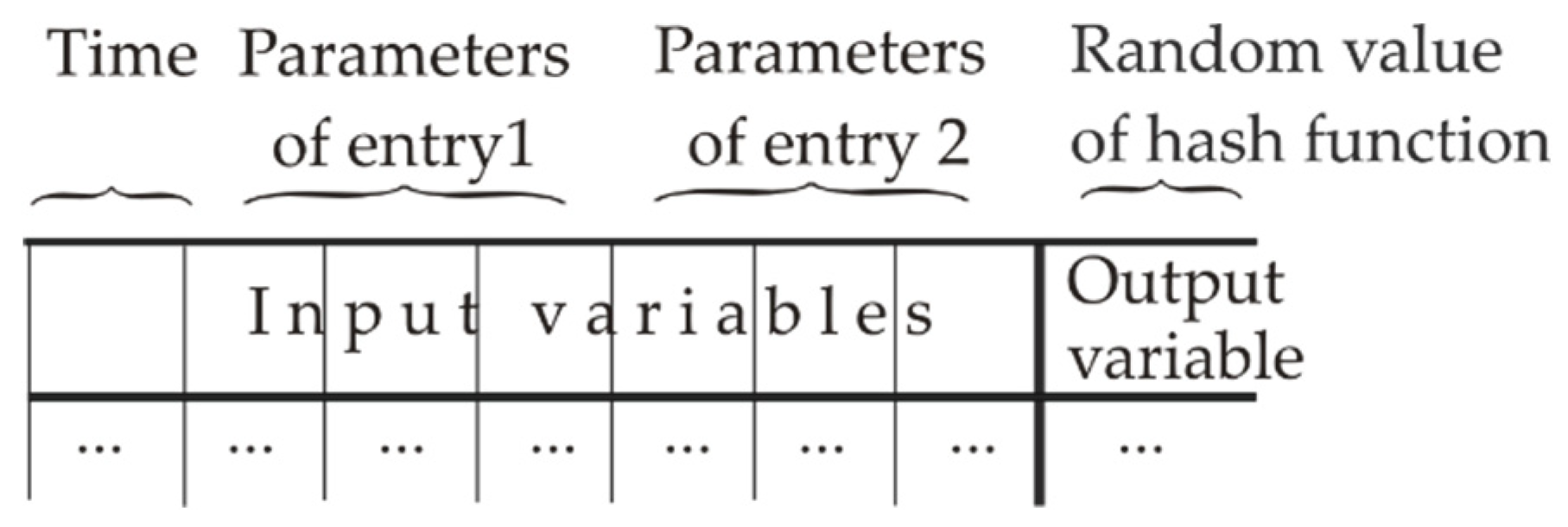
2.1. The Structure of MVL Function

Traditional design of models for robotic agents implies the formation of mathematical expressions intrinsically based on Boolean logic operations A N D ,   O R ,   N O T , but MVL logic calculus of Allen–Givone algebra (AGA) is based on more general operators M a x i m u m ,   M i n i m u m , and L i t e r a l [29]. The comparison of MVL operators with Boolean ones and other possible logic systems was carried out in [23,30,31]. AGA [29] is one of several known versions of MVL models that operates with discrete MVL functions y = f ( x 1 , , x n ) , given for n input variables x 1 , , x n and one output variable y . Specifics of AGA are that instead of two truth levels {0,1} in Boolean logic, all its input variables x 1 , x 2 ,   , x n and the output variable y can have k discrete truth levels: x 1 ,   x 2   , , x n   , y L = { 0 , 1 , ,   k 1 } , i.e., they are natural numbers. In earlier designed MVL coding schemes [23,30,31] for 8-bit controllers, k was supposed to be 256, which was enough even for the description of secret coding procedures and communication messages. However, the further proposed MVL model of distributed ledger is to be based on definitions and algorithms of AGA [29] defined for functions with the larger number of truth levels k .
The complete set of non-Boolean operators [29]
< 0 ,   1 , ,   k 1 ,   X ( a , b ) , , + >
ensures the possibility to represent arbitrary function y = f ( x 1 , , x n ) as some combination of logic operators taken from the list given further:
  • 0 ,   1 , ,   k 1 are constants;
  • operator M i n i m u m   ( x i , x j   ) or M I N is marked by (∗) and means the choice of the minimal one in the pair x i , x j   ;
  • operator M a x i m u m   ( x i , x j   ) or M A X is marked by (+), it means the choice of the maximal value in the pair x i , x j   ;
  • operator X ( a , b ) is called L i t e r a l and is given by Equation (5):
    X ( a , b ) = { 0 ,             i f   b < x < a k 1 ,       i f   a x b   ,
    where for any X ( a , b ) , always b a , and a , b   L = { 0 , 1 , , k 1 } .
Equation (2) demonstrates that operator Literal, in fact, resembles the discrete band filter with variable lower and upper limits. This expression is either equal to the maximal truth level k 1 or 0 , which simplifies the analysis of data.
It was commented in [30] that the general structure of M I N and M A X operators dates back to basic definitions of the set “lattice” and its operators “Infimum” and “Supremum”, which namely for the “lattice” were proved to be MAX and MIN. In fact, these binary operators M A X (   x 1 , x 2 ) and M I N ( x 1 , x 2 ) are the comparison of two logic values x 1 , x 2 , which can reproduce Boolean operators A N D ,   O R if written as appropriate rows into the MVL truth table. However, MVL operators do not possess some specific theorems of Boolean logic, providing its more universal properties. Thus, AGA is a more general but very poor set of tools for data procession, which mainly provides calculation of arbitrarily given MVL functions and their minimization (i.e., simplification), described in detail in [30]. For example, traditional arithmetic operations are not defined in AGA, and they can be reproduced in AGA only by the specially given MVL functions with appropriate truth tables. At the same time, AGA calculus [29] provides primitive logic calculations, whose result is predictable only for a specific numerical data set and does not give appropriate tools for design of trapdoors and schemes to break cryptographic one-way functions and hash ones.
Equivalent representations of MVL functions include truth table, logic expression, and matrix form [29]. Any MVL function y = F ( x 1 , , x n ) can always be given by the truth table shown in Table 1, which has the overall number of rows equal to k n , as in Boolean logic it has only 2 n ones. Thus, for large values of k (say, more than 256) and n (several dozens), the number of rows can be extremely large and, in reality, one can use only some part of the truth table. That is why MVL function is much more attractive [31,32,77] for modelling complicated systems, cryptography schemes, and random hash functions than the Boolean one.
The column for output variable y should be filled in by some set of logic constants C = { 0 ,   1 , ,   k 1 } . According to [29], any input vector x 1 , , x n , i.e., every row of the truth table with nonzero y , has equivalent product term shown to the right of Table 1, and they are written via logic constants, L i t e r a l s , and operators M I N (marked ∗) and MAX (marked +). In this product term, the value of F ( x 1 , , x n ) is taken from the column “Output” in Table 1, and L i t e r a l s are to be filled in by equal parameters, e.g., X ( 1 , 1 ) .
Unfortunately, the truth table is a convenient tool only for a small number of input vectors, so that real AGA models should use either formal expression (3) written via AGA operators as a set of product terms, or equivalent matrixes [77]. The function given by the truth table (see Table 1) responds to the set of product terms
y = f ( 0 , 0 , , 0 ) X 1 ( 0 , 0 ) X 2 ( 0 , 0 ) X n ( 0 , 0 ) + + f ( 0 , 0 , , 1 ) X 1 ( 1 , 1 ) X 2 ( 0 , 0 ) X n ( 0 , 0 ) + f ( k 1 , k 1 , , k 1 ) X 1 ( k 1 , k 1 ) X 2 ( k 1 , k 1 ) X n ( k 1 , k 1 ) .
One should especially note that, according to definitions given in [29], Literals written for separate rows of the truth table and shown to the right of Table 1 have equal values a = b   L = { 0 , 1 , , k 1 } for product terms. So, for the arbitrary truth table, one can always write formal Equation (3), which has equal lower and higher parameters a,b in Literals the structure f ( 0 , , 1 ) X 1 ( a 1 , a 1 ) X 2 ( a 2 , a 2 ) X n ( a n , a n ) . This notation means that Literal is nonzero only for one natural number n = a = b. However, further simplifications and transformations based on subsuming of product terms can shorten the computing time. Such modification of logic expressions can be held by means of minimization procedure by consensus method [29]. Then, the set of product terms can be shortened, but some parameters a,b of its Literals will be modified. In this case, notation X(a,b) with different parameters a b means that Literal is nonzero for the discrete set of values a, a + 1, a + 2,…b − 1, b. It is essential and advantageous for MVL data protection methods that minimization procedure [29,30] strongly depends on the specific set of used data and is “unpredictable” beforehand, which prevents the design of hidden trapdoors. Besides this, any such legal or illegal procedure will change the set of Literals, i.e., expressions for Literal will receive different lower and higher indexed parameters a,b. In addition, the advantage of procedures proposed in the present paper is that they do not initially need minimization procedures. Within the framework of the present paper, logic minimization will finally be necessary for the large number of rows in the truth table or for large number of entries in the MVL model. That substantially simplifies processing and verification of MVL models.
Another possible case of transformation of Literals parameters without minimization refers to Section 3.3, where in Equation (9) some fragment of the truth table is subdivided into loyal and prohibited subsets of rows, which is based directly on total estimates of unused (or prohibited) rows for the known numbers of all possible rows and already used ones.
In turn, its consensus minimization procedure [29] is based on extension of initially given function and adding of so-called “don’t care states” with constants k 1 substituted into the function. The choice of such states for extended function leads to multi-criteria optimization task that additionally complicates very long minimization procedure. Respectively, if namely MVL function is used as a learned hash or a ledger function, its illegal modification is a very costly task.
In the present paper, for clarity, mainly truth tables are used, but for other modelling stages, one should use more compact equivalent representation of MVL function, written as the set of matrixes in Equation (4), which reproduce parameters a , b and logic constants used in Equation (3):
A u = ( a 11 a 1 n a k 1 , 1 a k 1 , n ) ,   B u = ( b 11 b 1 n b k 1 , 1 b k 1 , n ) ,   C   = ( c 11 c 1 v c k 1 , 1 c k 1 , v )
where: b i j a i j ,   n —is the number of input variables, k —is the number of truth levels, and u { 1 , 2 , , v } . Matrixes A u and B u in Equation (4) specify indexed sets of parameters a and b in Literals X j ( a , b ) . Matrix C in (4) shows the set of constants for all product terms, united by operator M a x (+), and   v is the number of columns of product terms. Initially, due to Table 1, matrix C will have only one column, but further minimization of MVL function [29] can modify it.

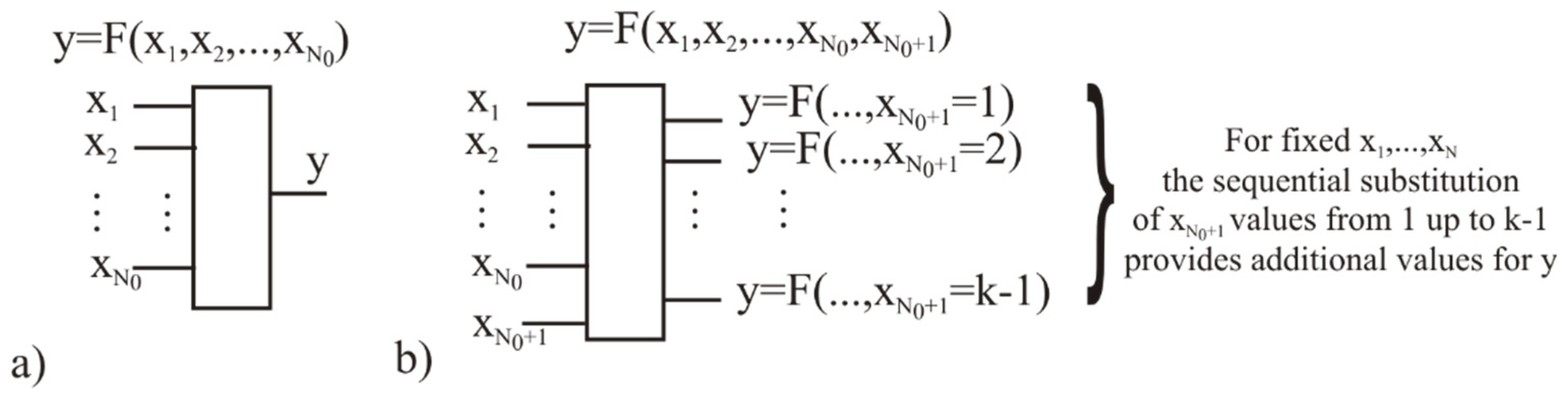
2.2. Transformation of Dimension of AGA Function

According to basic definitions [29], the number of input variables for AGA function is not limited, but it has one output variable (see Figure 3a). However, verification procedures need to output many signals for one input vector. In order to avoid modification of AGA calculus, one can simply add one or several input variables in order to obtain the allocated counter cycle for outputs. In Figure 3a, the basic AGA function y = F ( x 1 , x 2 , , x N 0 ) has the number of input variables equal N 0 , but the only output variable can describe only k 1 output values. However, if one will define AGA function F ( x 1 , x 2 , , x N 0 + 1 ), shown in Figure 3b, it can produce the extended number of output signals in the external cycle, obtained by the sequential substitution of values for x N 0 + 1 . Such a procedure is reasonable to carry out after the calculation of all L i t e r a l s in product terms with x 1 , x 2 , , x N 0 . Note that the value x N 0 + 1 = 1 but not 0 should be used for the first output signal to provide nonzero product term for it. This small limitation seems not to be substantial.

3. Results

The MVL version of collective ledger and the linked list are proposed to be based on the procedure of the collective generation of values of a random hash function by Q participants of the network pool of users or nodes, motivated in mutual service and shown in Figure 4 as V 1 , V 2 , , V Q . These nodes are called verifiers, as they verify entries (or messages) coming from P   and other participants of the pool. It is supposed for simplicity that only one mobile agent   P can represent the “interests” of some MASs and is responsible for transfer of entries between this MAS and network nodes. This agent P is further called the prover, as in [33], because its data should be approved, corrected, or restored with the help of external network nodes V 1 , V 2 , , V Q . Verification, authentication, and identification data coming from P to the external nodes are described by entries e = { e 1   , , e n }. The entry e = { e 1   , , e n } received at time t has n fields represented as natural numbers and can be interpreted, e.g., as a message such as “(1) vehicle N”—(2) “is certificated for”—“(3) ecology class Euro…”—…—(n) “date”. For simplicity, we do not consider any language structures here.

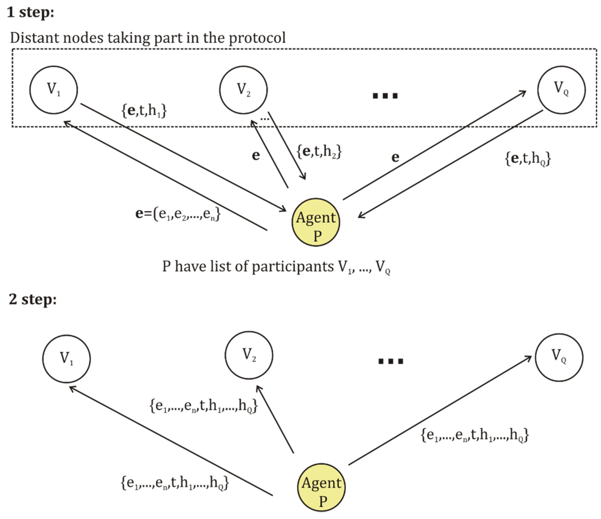
3.1. Collective Generation of Data for MVL Storage and Ledger Functions

In Figure 4, the simple procedure is proposed to accumulate data collectively, which is necessary for the generation of an MVL logic-linked list and ledger functions. The prover P is considered as the participant of the pool of loyal nodes. The prover agent wants to add some entry e = { e 1 , , e n } into the distributed backup storage, which is being sustained collectively by the pool of network nodes. We suppose that this entry is not confidential and does not need preliminary secret coding, but even this procedure will not disturb the procedures disclosed further. The prover P has the list N N = { N 1 , ,   N Q } of identifiers (or simply numbers 1 , , Q ) corresponding to verifiers V 1 , V 2 , , V Q , who are agreed to provide the service. Principally, some of the participants can be switched off or busy, so that full list can be unused, but this does not change the scheme, and for simplicity we suppose that all registered participants are taking part in the formation of the entry. The prover P tags the entry e = { e 1   , , e n } as a new one and sends it via the network to one of the participants, which is taken to be V 1 . Verifier V 1 assigns to this entry the time stamp t and some randomly chosen natural number h 1 . After this, V 1 writes the set of parameters { e ,   t ,   h 1 } in its memory and sends the copy back to the prover. Further, prover P writes the obtained parameters in memory and sequentially sends the pair { e ,   t } to all other nodes from the list. As a result, it accumulates random hash function values h 1 , , h Q assigned by verifiers V 1 , V 2 , , V Q to the pair { e ,   t } . After this, P sends the finally formed set { e 1 , , e n ,   t , h 1   , , h Q } to all involved participants according to the earlier used list. Further, this set of data is to be represented as a separate logic product term in the collective ledger function.
The procedure given above is shown further as Algorithm 1. Its necessary preliminary conditions for entry formation include:
  • complete number of involved loyal verifiers Q should respond to Q k 1 ;
  • waiting time t w a i t is limited for the reply from the verifier   V j + 1 . If it is exceeded, then the zero value should be assigned to the corresponding h j + 1 ;
  • every node taking part in the protocol should possess either quantum random number generator or RO module with the scheme proposed in [77], which should generate the set of randomly given hash values h j to make the formation of entries unpredictable and corresponding product terms;
  • all the assigned parameters are natural numbers.
Algorithm 1: Collective accumulation of hash values for entry
Input
k  
Q  
t w a i t
e = { e 1   , , e n }
Number of truth levels
List of adresses for Q participants of protocol
Waiting time for reply entry e = { e 1   , , e n }
Preliminary prepared entry
 1.Prover P assigns counter j = 1
sends e = { e 1   , , e n } to the verifier V 1 according to the
list of addresses
 2.Verifier V 1 assigns time stamp t   to e
assigns randomly chosen h j
writes the set { e ,   t ,     h j } in its memory
sends the copy of { e ,   t ,   h j   } to prover P
 3.Prover   P waits for reply during t w a i t ,
if reply { e ,   t ,   h j } has come writes it in its memory
           otherwise writes it with h j = 0
assigns j = j + 1
sends pair { e   ,   t }   to the next verifier V j + 1
 4.Verifier V j + 1 assigns randomly chosen h j + 1
writes the set { e ,   t ,   h j + 1   } in its memory
 5.Verifier V j + 1 sends the copy of { e ,   t ,   h j + 1 } to the prover P
 6.Prover P checks if j = Q   , if yes goes to step 7,
        otherwise repeats steps 3–6
 7.Prover P sends { e 1 , , e n ,   t , h 1   , , h Q }   to all verifiers V 1 , V 2 , , V Q
OutputLedger entry { e 1 , , e n ,   t , h 1   , , h Q } for each of verifiers V 1 , V 2 , , V Q
As the prover sends its entry e according to the preliminary formed list of participants, the number of replies does not exceed Q. As the limiting time parameter t w a i t is assigned in the reply only by the first verifier, its possible further illegal modification in one of verifiers does not influence the other’s replies and will contradict the data of the simple majority of verifiers and will be excluded at the stage of decision making. The absence of the verifier’s reply is marked by a zero hash, which is fixed in all other procedures and can be further used for analysis of attacks. The waiting time t w a i t period for reply can be limited by the average and variance values estimated for all involved verifiers.
The accumulated set of user data and random hash values above can be directly used for the formation of the simple version of the logic ledger function, but a more pragmatic variant is to firstly generate the separate backup storage function F s t , accessible for distant reconstruction if the prover has declared a correct access key. The simple variant here responds to the reconstruction of entry e m when the prover declares (i.e., substitutes as input variables) the collectively generated key given by the hash values h 1   , , h Q . The request is sent according to the known list of participants and is considered correct if it is reproduced by the majority of participants. Another simple variant responds to the approval of certificate hash values h 1   , , h q extracted from the storage for the declared entry   e m . Here, the reliability of data also can be estimated according to the majority of replies. More complicated schemes such as the “proof-of-work” one in the BC protocol [37,38,39] are principally possible, but they seem to be not actual here.
If all participants of the collective protocol possess identical data sets { e 1 , , e n ,   t , h 1   , , h q } written for every entry in the storage, then identical storage function F s t can be generated in all the involved verifiers using the known scheme. Two simple variants of storage function mentioned above are shown further as the function of entries F s t e and the function of hash values F s t h . As the key to extracting data from backup storage should be realized by hash values h 1   , , h Q assigned by Q network verifiers, then namely these hash parameters are to be used as input variables in F s t e . In addition, the set of entries e m = { e 1 , m   , , e n , m } should be considered as the values of output of the variable y . Such a procedure should use the general algorithm given in [29] and Table 1.
The formation of the MVL storage function F s t h is shown in Table 2. This truth table follows the general format, so that besides parameters h 1   , , h Q it contains an additional counter of verifier q . For brevity, Table 2 demonstrates the product term only for final entry e m , and all previously added product terms are not shown. One should especially note that, by default or according to the agreement of participants, the first row in the truth table can be filled in by arbitrarily taken random numbers. If some verifier from the list was switched off and did not take part in the formation of F e n t r , it is necessary to assign 0 to its hash value in the row. Here, hash values h 1   , , h Q will be the key to the verification procedure, when some of participants will want to restore the entry with critical data.
The second version of storage function F s t e can be based on the same data set { e 1 , , e n ,   t , h 1   , , h q } and is shown in Table 3. It is to approve certificate hash values h 1   , , h q for the declared entry   e m , i.e., it can output numbers of licenses or permission if entries contain data referring agent and MASs. Actually, this function should reproduce collectively assigned random hash values.
A special comment should be given to the assigning of random values to the hash function. Their use is determined by the desire to provide an unpredictability of parameters for the MVL function, the storage function, and the ledger function. As most secured data protection schemes [80] are grounded in the OTP method and random data, AGA verification should also follow this trend, excluding preliminary forecasting of backup functions. The method to assign random hash values in the algorithm described above can use the RO scheme proposed earlier in [77] for the protocol PU. The idea of this scheme supposes the quantum random number generator (QRNG) [78] and learning procedure, forming the MVL function according to the algorithm proposed in [77]. An interesting aspect here is that, instead of a hardware QRNG, it is principally possible to use software for one of the known and tested types of cryptography hash functions such as, e.g., SHA256 [81], which guarantees a high quality of hash values set. The principal advantage of the MVL function here is that it can be taught to reproduce any reliable and tested source of random bit sequences with a fixed length, including both hardware QRNG and software SHA256 data.
In Table 2 and Table 3, schemes demonstrate two complementary procedures to represent data as AGA functions and to extract them from a reserve backup storage of entries written by logic product terms. However, these two complementary functions discussed above have no internal tools yet to prevent the modification of data, but the calculus of AGA also provides a logic analog of a linked list used in BC schemes [37,38,39].

3.2. MVL Function of Two Entries as a Base Model for the Logic-Linked List

In order to prevent illegal modifications of entries written in some format unified by participants, it is proposed to form the logic ledger function F l d g by product terms, containing pairs of entries obtained at different time moments t m and t m s (see Figure 5). In such a ledger scheme, the function formation responds to the generation of the AGA truth table, where fields of entries may have repeated values if they respond to the same agents, tasks, documents, permissions, plans, and used resources. In order to split such data into separate rows of the MVL ledger function, every entry receives time stamp parameter t and the number of entry m in the ledger. External network nodes are to assign random hash values h in order to exclude the prediction of the ledger function and to simplify its verification, as the uniform distribution of random numbers is appropriate for revealing possible modifications.
The last entry obtained at time moment t m is written as   e m = { e 1 , m   , , e p , m } , where m is the number of the entry in the ledger and p is the chosen number of fields in the entry. An earlier obtained entry e m s = { e 1 , m s   , , e p , m s } corresponds to the time moment t m s . In order to confirm authenticity for two entries, the ledger should contain the data of both of them and sets of random keys unique for each of them. In Figure 5 this responds to the shift to right of the position of entry e when a new entry arrives.
Definition 1.
Logic ledger function or a linked list of logic entries is given within AGA as a hash function
h ( m , s ) = F l d g ( m , s ,   t , e 1 , m   , , e p , m ,   e 1 , m s   , , e p , m s ,     h 1 , m , , h Q ,   m ,     h 1 , m s , , h Q ,   m s )
In Equation (5), m is the number of the last entry in the ledger, s is the shift of the number for the previous entry, t denotes the assigned time stamp for the last entry ,   e 1 , m   , , e p , m are the parameters of the last entry e m ;   e 1 , m s   , , e p , m s correspond to parameters of the earlier received entry e m s , h 1 , m , , h Q ,   m are hash values assigned by network verifiers to the last entry e m h 1 , m s , , h Q ,   m s are hash values of the earlier received entry e m s , and q is the number of a verifier, q = 1,.., Q. Non–indexed parameters m ,   s ,   q and indexed parameters t ,   e ,   h are natural numbers. For brevity, Equation (5) can be rewritten briefly as:
h ( m , s ) = F l d g ( m , t , e m   ,   e m s   , h m , h m s )
The specifics of data backup for autonomous robotic agents are that the verification of data should include the possibility of its use both by a distant human expert and by a software bot. That is why a logic-linked list should not be accented only on the procedure of rigid binding of a block of data to the pointer of the next block, as in BC schemes [37,38,39], which can be realized by the special field-to-code data pointer just in the entry. Certainly, the assigning of data pointers should be adapted to a specific software platform.
Thus, using the same set of basic rules disclosed by Table 1, Table 3 and Table 4, Equation (5) for the logic ledger can be written according to its truth table. As it was mentioned in the previous section, by default storage functions F s t e and F s t h should have the first row of the ledger filled in by a randomly chosen set of data. The output variable column should contain random hash values for all rows in order to exclude any preliminary prediction of the ledger function. In Table 4, the new entry is tagged by the number m and the time stamp t . For a simple version of the ledger parameter, s can be taken as equal to 1 and Equation (5) for h ( m , 1 ) will simply connect the last and the previously received entries such as with blocks of data in BC schemes [37,38,39,53,54].
According to definitions given in [29] and commented in Table 1, Table 2 and Table 3, the last row of the truth table shown in Table 4 for the ledger responds to the product term Equation (7) tagged with the number m and time t m :
p r o d u c t   t e r m   m = h m ( m , 1 ) X m ( m , m ) X t ( t m , t m ) X e , 1 , m ( e 1 , m , e 1 , m ) X e , 1 , p ( e p , m , e p , m ) X h , 1 , m ( h 1 , m , h 1 , m ) X h , Q , m ( h Q , m , h Q , m ) X e , 1 , m 1 ( e 1 , m 1 , e 1 , m 1 ) X e , p , m 1 ( e p , m 1 , e p , m 1 ) X h , 1 , m 1 ( e 1 , m 1 , e 1 , m 1 ) X h , Q , m 1 ( e Q , m 1 , e Q , m 1 )

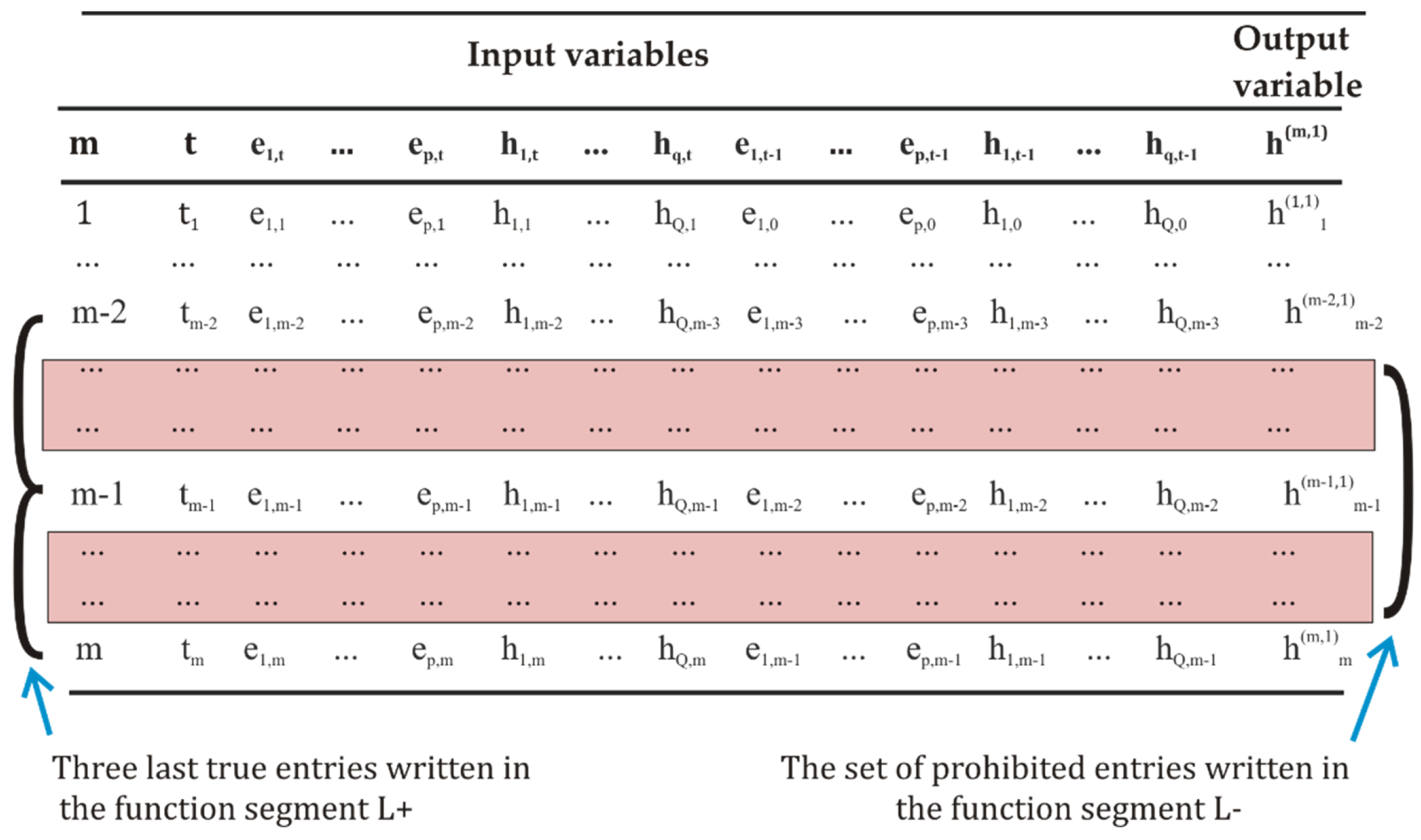
3.3. The Scheme to Exclude Illegal Modification of Non-Specified States of AGA Function

The task to protect the ledger from illegal data modification includes the problem of minimizing the frequency of needed full checks of the overall list of entries and simplifying verification procedures. However, the possible consequences of various illegal modifications in the logic ledger can differ. The illegal deleting of rows or adding of fake rows will distort data written after specific m and t values in the truth table, and it can be revealed by direct access to that ledger. Nevertheless, a more dangerous attack can be carried out if the logic minimization of AGA expressions [29,30] is periodically held in order to shorten the ledger and its computing time. Although this minimization is not an obligatory procedure, participants of the protocol can be interested in it to lower expenses. Namely, this procedure can hide the results of illegal replacement of the true logic constant in a product term by a fake value, as it is disclosed by Example 1.
Example 1.
Let us consider a ledger with k = 32,656 and input variables x 1 , x 2 , x 3 ,   x 4 , where the product term 567 X 1 ( 24 , 24 ) X 2 ( 1275 , 1275 ) X 3 ( 317 ,   331 ) X 4 ( 587 , 1144 ) is one of the ledger’s entries. A possible attack of an eavesdropper to compromise the ledger is to add a fake entry, where the parameters of Literals are not modified but the randomly chosen hash value, assigned as logic constant C = 567, is replaced, e.g., as 830. Further minimization here can delete clear signs of attack and may complicate its verification, and in order to avoid this one should use the basic definition of subsuming of product terms, which is the critical component of simplification procedures for AGA functions [29]. Further, the definition used is cited from [29] and was commented on in detail in [30].
Definition 2.
Product term  r 1 X 1 ( a 1 , b 1 ) X n ( a n , b n ) subsumes another product term  r 2 X 1 ( c 1 , d 1 ) X n ( c n , d n ) , if and only if conditions (1) and (2) are true:
  • r 1 r 2 ;
  • c i a i b i d i for all X i , i = 1 , , n .
Using this definition for Example 1, one can see that 567 830 is true and c i = a i b i = d i for all X i , i = 1 , 2 , 3 , respectively. Minimization after illegal replacement of data will provide further that the first product term will subsume the second one and consequently will be deleted:
567 X 1 ( 24 , 24 ) X 2 ( 1275 , 1275 ) X 3 ( 317 ,   331 ) X 4 ( 587 , 1144 ) + + 830 X 1 ( 24 , 24 ) X 2 ( 1275 , 1275 ) X 3 ( 317 ,   331 ) X 4 ( 587 , 1144 ) = = 830 X 1 ( 2 , 24 ) X 2 ( 1275 , 1290 ) X 3 ( 317 ,   331 ) X 4 ( 587 , 1144 ) .
Thus, the ledger function can be compromised by illegal changes, although further comparison of the true number of product terms and values of m and t will disclose the mismatch, but it will be difficult to determine the step when it is carried out.
If participants of the protocol want to use minimization procedures to shorten the ledger and at the same time prefer to exclude possible illegal modifications, then an AGA model of a ledger provides the original method to prevent modifications hidden by minimization. The advantage of this scheme is that it is grounded only in basic definitions [29] and does not need any additional theorems or constraints. In order to apply this method, the participants of the protocol should agree to use constant k 1 only as a “technical” parameter for the minimization procedure [29], which will help to uniformly describe all parts prohibited for modification of the truth table, as illustrated in Figure 6. To obtain a formal logic model for the prohibited part of the truth table, one should define complementary product terms, assigning maximal logic constant k 1 to all unused rows located “between” both of true entries in the multiparametrical space given by the truth table. Such a prohibited product term will be the subsumed term for any fake product terms having less logic constants and various sets of input variables.
The procedure is proposed further to define a complementary set of prohibited product terms for the truth table, which is general enough and can be used not only for a logic ledger function with two entries but also for any storage AGA function. That is why, for brevity, let us consider a logic function containing only three input variables x 1 , x 2 , x 3 , where the last two entries (or rows) were added into the truth table at different time moments t m and t m 1 , such as in Figure 6. Such a segment of the function includes only true entries, it is tagged by “+” (i.e., a “good” segment), and it can be written as Equation (8):
F u n c t i o n   s e g m e n t   m 1 ,     m + = h m 1 X 1 ( x ¯ 1 , x ¯ 1 ) X 2 ( x ¯ 2 , x ¯ 2 ) X 3 ( x ¯ 3 , x ¯ 3 ) + h m X 1 ( x = 1 , x = 1 ) X 2 ( x = 2 , x = 2 ) X 3 ( x = 3 , x = 3 ) .
Double index m 1 ,   m in the left part of Equation (8) indicates the numbers of entries to be processed.
If the segment of the logic function with true entries is given by Equation (8), then the corresponding segment with prohibited entries also can be designed, as one can describe the total border between two classes (or function segments) given in the multiparametrical space given in AGA [30]. The principle of formation of prohibited product term p t m 1 , m , describing all possible potentially fake entries, is very simple: it one should include all possible neighboring entries (or rows in the truth table), i.e., whose values of variables differ by one or more. If only one of the variables provides unused entries, other variables may have values coinciding with true entries.
Prohibited product term p t m 1 , m should contain logic constant k 1 , which will provide subsuming of any illegally added product terms with smaller constants written into the prohibited part of the truth table. Such a property of AGA is being actively used in its minimization method based on “don’t care states” [29]. According to it, the idea of minimization in AGA is grounded in the extension of the initially given AGA function. One should initially add unused sets of input variables into the truth table and assign logic constants   k 1 to them, thus defining by hand the “don’t care states”. These new product terms will be the subsumed ones for all added fake product terms with smaller constants and equal sets of variables [29], so that one can also exploit this experience of a minimization procedure and intentionally assign constant k 1 to all unused product terms, thus excluding their use by eavesdroppers.
In order to obtain formal expression for prohibited product term p t m 1 , m , one can firstly guess the appropriate logic expression, propose the algorithm for its realization, and further prove it.
In the further proposed Algorithm 2, a necessary preliminary condition is that one should arrange entries in the truth table according to the sequential enlargement of time variable and entry numbers m . Note that further x ¯ i corresponds to time moment t m 1 , and x = i responds to t m .
Algorithm 2: Formation of the prohibited segment of an AGA function for the last entry h m X 1 ( x = 1 , x = 1 ) X 2 ( x = 2 , x = 2 ) X p ( x = p , x = p ) and the previous one
h m 1 X 1 ( x ¯ 1 , x ¯ 1 ) X 2 ( x ¯ 2 , x ¯ 2 ) X p ( x ¯ p , x ¯ p ) .
Input
k  
Q  
t w a i t
e m
e m 1
Number of truth levels
List of addresses for Q participants of protocol
Waiting time for reply
Last   entry   h m X 1 ( x = 1 , x = 1 ) X 2 ( x = 2 , x = 2 ) X p ( x = p , x = p )
Previously   received   entry   h m 1 X 1 ( x ¯ 1 , x ¯ 1 ) X 2 ( x ¯ 2 , x ¯ 2 ) X p ( x ¯ p , x ¯ p )
1.Set   i = 1 for the counter of input variables, i = 1, …, p
2. Calculate   b = M a x   ( x ¯ i , x = i ) ,   a = M I N   ( x ¯ i , x = i )
3. If       b i a i 2     write   Literal   as   X i ( a + 1 , b 1 ) ,
    otherwise go to step 6
4.Set   z = 1 ; where z is the flag of prohibited rows
5.Go to step 8.
6.If b i a i < 2     write   Literal   as   X i ( a , b )
7.Set flag z = 0
8.Set counter i = i + 1
9.If   i p , go to step 2, otherwise go to step 10.
10.If z = 1, then write prohibited segment as
F u n c t i o n   s e g m e n t m 1 ,     m = ( k 1 ) X 1 ( , ) X p ( , ) ,  
  if z = 0, then write prohibited segment as
   F u n c t i o n   s e g m e n t m 1 ,     m = 0 .
OutputThe set of parameters of the product term, defining the prohibited part between two given entries
Proof of correctness: The prohibited product term according to its idea cannot coincide with the true one, thus its Literals parameters are natural numbers and in the formal expression should differ at least for one. Due to the definition of operator Literal [29], always for any input variable b i   a i . As condition b i a i < 2 is equivavent to b i < 2 + a i , but always b i a i , then according to Figure 7, possible values of b i are either a i or a i + 1 . Non-coinciding with true ones, the prohibited segment cannot then be inserted. As condition   b i a i 2 responds to condition   b i a i + 2 , a non-coinciding prohibited product term can include at least one possible value, and briefly this can be written as X i ( a + 1 , b 1 ) .
Based on Algorithm 2, it is more appropriate to design the joint segment of the logic function by combining both true entries and the prohibited segment “between” them. Such a joint expression of Equation (9) tagged by “±” should contain three product terms: the true product term for previous entry   p t m 1 + , tagged by number of m 1 , the true product term for the last entry p t m + , tagged by number m , and the prohibited product term p t m 1 , m uniting all unused and potentially dangerous rows located between the last and the previous entries:
F u n c t i o n   s e g m e n t m 1 ,     m ± = h m 1 X 1 ( x ¯ 1 , x ¯ 1 ) X 2 ( x ¯ 2 , x ¯ 2 ) X 3 ( x ¯ 3 , x ¯ 3 ) + ( k 1 ) X 1 ( M i n   ( x ¯ 1 , x = 1 ) + 1 , M a x   ( x ¯ 1 , x = 1 ) 1 ) X 2 ( M i n   ( x ¯ 1 , x = 1 ) , M a x   ( x ¯ 1 , x = 1 ) ) X 3 ( M i n   ( x ¯ 3 , x = 3 ) , M i n   ( x ¯ 3 , x = 3 ) ) + h m X 1 ( x = 1 , x = 1 ) X 2 ( x = 2 , x = 2 ) X 3 ( x = 3 , x = 3 ) .  
Thus, according to Algorithm 2, Equation (9) can describe sets of prohibited rows even without directly composing the truth table for all possible states. The prohibited part, if necessary, can also be written as a separate AGA function.

3.4. Representation of Quantum Protocol by AGA Function

The model of the logic ledger h ( m , s ) = F l d g ( m , t , e m ,   e m s ,   h m , h m s ) proposed above describes a system whose states are linked by a logic expression for entries taken for different time moments. This model principally can be used for description of an arbitrary procedure, including various classical and quantum protocols, as the truth table and its equivalent product terms are simple and visual tools for preparation and debugging of a logic function. This is illustrated further for the case of the route verification scheme cited in Section 1.2.
Verification procedures discussed in [32] and in Section 1.2 suppose that the prover and the verifier in each of the checkpoints interact as two different agents and execute the quantum protocol PU [33], which includes the transfer and measurements of classical and quantum signals.
Given above in the Figure 3, the actions of verifiers in every checkpoint were represented by the logic function F T N ( P ,   t ,   V 1 , V 2 , S 1 , S 2 , S 3 , S 4 , J ) [32], describing the work of crossed measurement modules. Input variable P here describes the initiating signal, t is time, and V 1 and   V 2 depict the transfer of two equal values q by entangled photons emitted by the EPR module. Indexed parameters S 1 , S 2 , S 3 , S 4 describe the transfer of classical test signals coming from the RO module via four crossed modules of the verifier, and J is the counter of the involved devices and procedures.
In its turn, actions of the prover P were represented in [32] by logic function F P (   t , Ψ   , S p 1 , S p 2 , S p 3 , S p 4 , J ) , where t is time, Ψ is the measurement of the photon polarization state | Ψ > in the basis B =   H ( x 1 x 2 x 3 x 4 ) responding to the 2D scheme of verification, S p 1 , S p 2 , S p 3 , S p 4 refer to measurements of classical signals sent to four verifier modules in the crossed scheme, and J is the counter of the devices and procedures. H is the random hash function of the RO [32,77] used by all verifiers and provers.
In order to model the interaction of the two agents commented above in the joint logic model, one should define the united AGA function F V P given by Equation (10) and disclosed in Table 5:
  y = F V P ( t , P ,   V 1 , V 2 , S 1 , S 2 , S 3 , S 4 , Ψ   , S p 1 , S p 2 , S p 3 , S p 4 , J v , J p )
This function is defined for the set of all 14 input variables used earlier in F P and F T N , and the output variable is given by the set of constants C 1 , , C 21 , for simplicity tagged as they are in paper [32]. According to [32,33,79], the used version of route verification protocol PU [33] was slightly adapted for the 2D case, and one checkpoint was considered as one verifier agent, which interacts with the prover agent. Their interaction corresponds to the protocol PU [33] and is subdivided into six steps tagged by time countdowns t 0 , , t 6 . Here, the value p of variable P obtained at t 0 refers to the initial signal coming from the prover and initiating the verification protocol, clocking scheme, memory device, random oracle, and microcontrollers or FPGAs. As time variable t is the same for both agents in [32,79], it does not need to be repeated twice in the united Equation (10). Two counters tagged J V and   J p principally can be replaced by one, but for simplicity they respond to the variables used earlier.
A special comment should be given to the other steps necessary for theoretically adapting the proven PU protocol [33], for practice. The choice of EPR scheme is critical here, as namely the simultaneous emission of two entangled photons provides maximal precision to the measurements of distances between the prover and the pair of verifiers (in the crossed detection scheme) in Figure 2. Respectively, the EPR scheme in the PU protocol determines the use of the polarization coding of qubits. However, the EPR scheme can have three variants, concerning the polarization of the pump photon [82,83]. The signal and idler photons can have the same polarization with each other and can coincide with the destroyed pump photon, but their equal polarization can also be orthogonal to the pump photon polarization. One more opportunity is that the signal and idler photons can have perpendicular polarizations. Thus, the truth table in Table 5 can potentially describe more details for these variants.
The choice of input variables leaves some alternatives for the procedure of input of the classical testing signals s 1 , s 2 , s 3 , s 4 generated by the RO module and controlled by variables   S 1 , S 2 , S 3 , S 4 . These classical signals should be sent to the prover by the verifier, and one can use a separate controller for them and thus replace four signals by one. The same alternative refers to signals s p 1 , s 2 p , s p 3 , s p 4 emitted by the prover and described by variables S p 1 , S p 2 , S p 3 , S p 4 .
It is necessary to emphasize that mobile agents are mainly associated with the atmospheric line for entangled data exchange during route passing by agents, but principally modifications of the protocol PU can be adapted for a fiber optics scheme with an EPR source of qubits [75].
Special commentary should also be given to the “-” symbols used in the rows of the truth table of the function   F V P for the shortened description of equivalent product terms. For the ideal physical set-up, one may fill in the truth table by the set of variables written in the table and replace all “-” with zeros, as there should be no signals for these variables. These zeros in the truth table correspond to Literals   X i ( 0 , 0 ) written in the product terms, as it was carried out for Table 1, Table 2 and Table 3. However, real signals may have nonzero levels due to transient processes and noise. That is why, for the real system, an ideal logic model may not work correctly, and noise deviations should be taken into account. This fact leads to the necessity to add into the truth table all possible rows containing the expected spectrum of all possible noise signals, which is a very wasteful method, but such information may be not accessible at the initial stage of design. At the stage of composing the truth table, one can suppose that input variables tagged by the symbol “-” are not observed and may have arbitrary transient values. This may be written by Literal ( 0 , k 1 ) k 1 , which can always be correctly “installed” into any shortened product term for omitted variables. This can be disclosed by Equation (11), where all variables tagged by “-” in Table 5 are omitted:
F V P = C 1 X t ( t 1 , t 1 ) X P ( p , p ) X j p ( j p 1 , j p 1 ) + C 2 X t ( t 1 , t 1 ) X s 1 ( s 1 , s 1 ) X j ( j 2 , j 2 ) + C 3 X t ( t 1 , t 1 ) X s 2 ( s 2 , s 2 ) X j ( j 3 , j 3 ) + C 4 X t ( t 1 , t 1 ) X s 3 ( s 3 , s 3 ) X j ( j 4 , j 4 ) + C 5 X t ( t 1 , t 1 ) X s 4 ( s 4 , s 4 ) X j ( j 5 , j 5 ) + C 6 X t ( t 2 , t 2 ) X j ( j 1 , j 1 ) + C 7 X t ( t 2 , t 2 ) X j ( j 2 , j 2 ) + C 8 X t ( t 2 , t 2 ) X j ( j 3 , j 3 ) + C 9 X t ( t 2 , t 2 ) X j ( j 4 , j 4 ) + C 10 X t ( t 2 , t 2 ) X j ( j 5 , j 5 ) + C 11 X t ( t 2 , t 2 ) X j ( j 6 , j 6 ) + C 12 X t ( t 5 , t 5 ) X v 1 ( q 1 , q 1 ) X v 2 ( q 2 , q 2 ) X j ( j 1 , j 1 ) + C 13 X t ( t 6 , t 6 ) X j ( j 1 , j 1 ) + C 14 X t p ( t 0 , t 0 ) X j p ( j p 1 , j p 1 ) + C 15 X t p ( t 2 , t 2 ) X ψ ( ψ , ψ ) X j p ( j p 2 , j p 2 ) + C 16 X t p ( t 2 , t 2 ) X s p 1 ( s p 1 , s p 1 ) X j p ( j p 3 , j p 3 ) + C 17 X t p ( t 2 , t 2 ) X s p 2 ( s p 2 , s p 2 ) X j p ( j p 4 , j p 4 ) + C 18 X t p ( t 2 , t 2 ) X s p 3 ( s p 3 , s p 3 ) X j p ( j p 5 , j p 5 ) + C 19 X t p ( t 2 , t 2 ) X s p 4 ( s p 4 , s p 4 ) X j p ( j p 6 , j p 6 ) + C 20 X t p ( t 3 , t 3 ) X j p ( j p 1 , j p 1 ) + C 21 X t p ( t 4 , t 4 ) X j p ( j p 1 , j p 1 ) .
However, the first product term   C 1 X P ( p , p ) X t ( t 1 , t 1 ) X j ( j 1 , j 1 ) in Equation (11) should be rewritten equivalently as:
C 1 X P ( p , p ) X t ( t 1 , t 1 ) X j ( j 1 , j 1 ) = C 1 X t ( t 1 , t 1 ) X P ( p , p ) X V 1 ( 0 , k 1 ) X V 2 ( 0 , k 1 ) X S 1 ( 0 , k 1 )   X S 1 ( 0 , k 1 ) X S 2 ( 0 , k 1 ) X S 3 ( 0 , k 1 ) X S 4 ( 0 , k 1 )   X ψ ( ψ , ψ ) X S p 1 ( 0 , k 1 ) X S p 2 ( 0 , k 1 ) X S p 3 ( 0 , k 1 )   X S p 4 ( 0 , k 1 ) X I V ( j 1 , j 2 ) X I P ( j 1 , j 2 )
The other 20 product terms also should be appropriately rewritten.
After the design and clarification of the involved hardware components, one should specify the appropriate noise parameters and reduce the band of indexed parameter b in Literals with ( 0 ,   k 1 ) from k 1 to some determined by noize value   b = . In other words, function y = F V P given by Equation (12) should be redefined after clarification of its noise parameters. Namely, this procedure will be correct, as there are no formal reasons to mix 0 and k 1 constants in one logic expression, and this should be carried out by hand in the final truth table for the new function y = F V P .
Using the procedures discussed above, one can write the function, describing the interaction of prover and verifier agents, into the ledger function as a reference procedure for tests or restoration. Position-based verification with protocol PU [33] here is not the obstacle, and both quantum and classical procedures can be united in the AGA logic model.
One more substantial note should be given, referring the further necessity to consider the model of trust for the interaction between the prover and the verifier. The joint logic function y = F V P discussed above has included the prover and the verifier as two different agents, according to their signals used in the verification protocol. However, their real interaction will also depend on the honest and dishonest behavior of the prover. In order to obtain a more detailed and realistic description of the verification procedure, it is further necessary to add a model of trust for their interaction.
Another interesting aspect of a fiber optics network segment is that advances in this field create the possibility to complement the PBC task and its more secured but specific PU by a less protected but more massive QKD protocol for the delivery of confidential digital data, such as photos, from the neural network database. At least, the recent research of the continuous-variable QKD scheme [84] can potentially be used for the design of k -valued truth models of AGA. Moreover, this paper discusses the trusted component of the phase noise model, so that the agent model for such hardware schemes can directly include several different noise models into the control scheme of the agent. That means there is a necessity to design more complicated models of trust, directly including physical parameters into agent models. It seems that multiparametrical models of AGA can be quite appropriate for the integration of such physical processes. The frequency polarization multiplexing system used in [85] additionally enlarges the interest in the continuous-variable QKD scheme. Besides this, the equalization enhanced phase noise [86] is attributed to wavelength division multiplexing schemes of fiber optics, which seems to be the most reliable scheme for the realization of multi-level logic. Moreover, the phase-coded noise compensation tools in QKD schemes [86] are attributed to dispersion compensating fiber, chirped Bragg gratings, dispersion-shifted fiber, and reduction of the chromatic dispersion effect by optimal initial pulse duration. All these schemes can potentially be considered as components for AI control agents, but the agent’s architecture and MVL model can differ substantially for them.

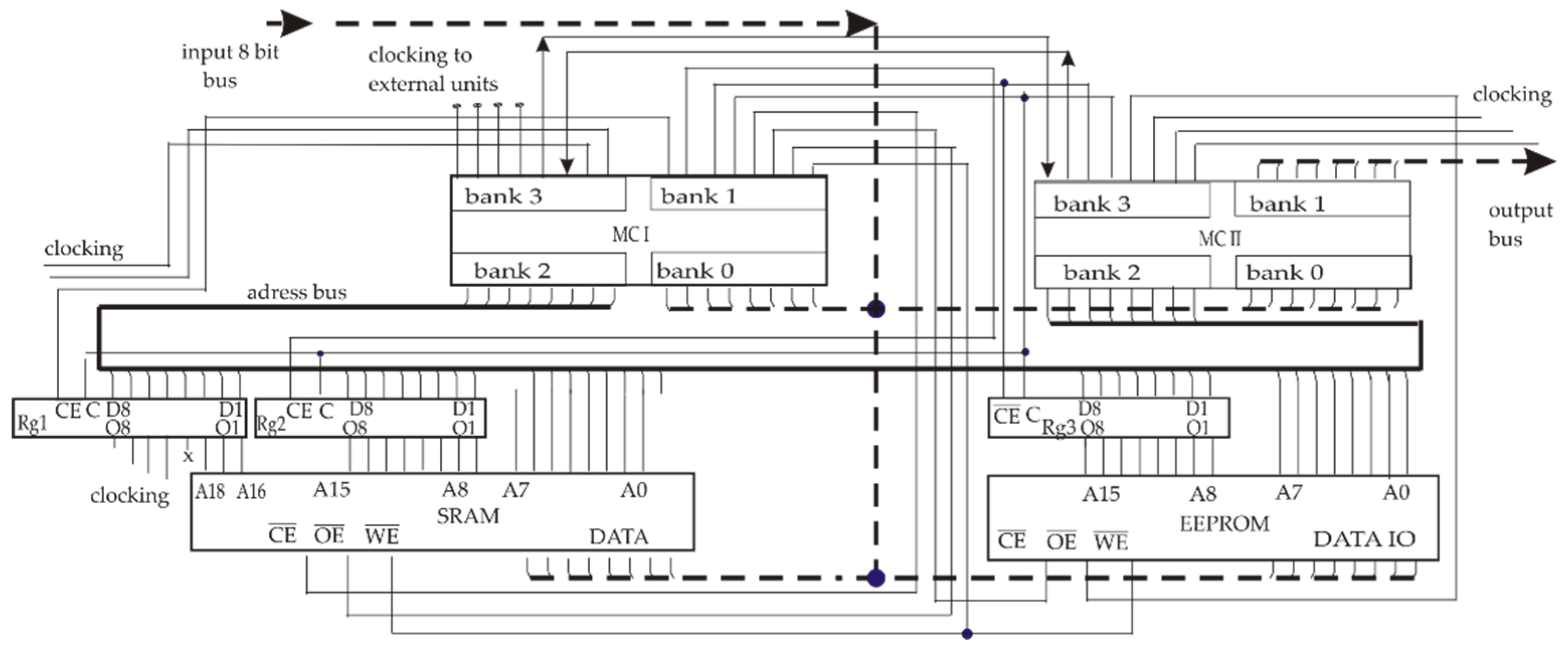
3.5. Computing Aspects of AGA Functions

As the ledger verification scheme for robotic agents is finally designated for data protection protocols and RO design, possible schemes of MVL procession should be obligatorily adapted to low-level programming and distributed schemes of microcontrollers and memory chips located inside a hardware agent. The two-controller testing circuit board was designed earlier for a fuzzy logic modelling device, which is shown schematically in the Figure 8, where input bus commutators used ADC in agents, but here it was used for the run of MVL function calculations. This external link controller, chips at the output bus, and some of clocking signals are not discussed here and are not shown, for brevity. Such a laboratory circuit board has a lower response in comparison with modern ARDUINO controllers [87], which are good for conjugation with modern computer ports and for quick access to embedded memory with limited capacity, but they are not appropriate for experiments with brunched multi-port schemes with active interaction of several controllers and high-capacity external memory chips, which is actually for the design of hardware agents. The 8-bit circuit board that was used included 1 MB SRAM, 512 KB ROM, and two 24 MHz ATMEL microcontrollers, possessing four input/output banks. The microcontroller MC1 was intended for data acquisition from external and network devices, and the second one, MC2, calculated the MVL ledger test function. Trigger registers Rg1, 2, and 3 are necessary here for the clocking of external memory chips. Addressing of the necessary SRAM cell is performed via bank (i.e., port) two of MC2 by means of trigger registers and inversed pins CE OE, WE. The data from SRAM and ROM are inputted via bank P0 of MC2.
The scheme shown in Figure 8 with the microassembler program for MC2 calculates the fit of the arbitrary external entry to the MVL ledger model with assigned quasi random hash value h ( m , 1 ) . For clarity, the hash value h ( m , 1 ) assigned to the last ledger entry is written in ROM, as in fact the RO device is to be the combination of the memory and random number generator, reproducing random hash for any repeated input signal. Respectively, it can be emulated by outputting value h ( m , 1 ) taken from the set   h ( 1 , 1 ) , …, h ( m 1 , 1 ) , h ( m , 1 ) , … h ( k 1 , 1 ) written in cells with addresses from, for example, #1 up to #255.
The test task included the processing of eight Literals shown in Table 2. In order to shorten the task, only one external hash value approves the entry, and every entry e consists of two components,   e 11 and e 12 . According to Table 4, the MVL template ledger function has emulated the numerical test data coming from the external agent and written them in fixed memory cells, as shown in Table 6.
The value of the calculated product term is to be written in SRAM cell #150.
The results of running of the program for microcontroller MC2 were also emulated by the simplest microassembler simulator AVSIM. Given a further short fragment of software demonstrates the calculation of only one Literal in a scheme with external memory addressing, in order to show the role of the agent’s architecture. Note that this program processes a general case of Literals with different low and higher indexed parameters of a, b in separate cells.
Fragment of the program for calculation of Literal X(a,b) in MC2.
ORG 0H
AJMP START
ORG 30H

LITERALS: MOV R6,#1; begin cycle for calculation of 8 Literals
SJMP PT
NEXTLIT: INC R6
PT: CLR C;
addressing cell #1 in SRAM
MA: MOV A,P0; read a for variable m
MOV R5,A; assign a to register R 5
… addressing cell #2 in SRAM…
MB: MOV A,P0; read b for variable m
MOV R4,A; assign b to register R 4
…addressing cell #101 in SRAM…
MT: MOV A, P0; read m t
MOV R3,A
COMPMA: SUBB A, R5; compare m t with a for X m
JNC LITMB; go to LITMB if bit C = 0 and m t is greater than a for Xm
AJMP PT_0;   m t does not fit to Literal and the whole product term is equal to zero
COMPMB: CLR C
MOV A,R4; assign b to accumulator A
SUBB A, R3; compare m t with b for X m
JNC CHECKLIT; if bit C = 0 i.e., m t less than b for Xm, then process next Literal
AJMP PT0;   m t does not fit to Literal and the whole product term is zero
CHECKLIT: CJNE R6,#8,PT;
PT0: …SRAM cell #150 addressing
MOV P0,#0; write 0 for product term into SRAM

END
A further example is shown for the shortest designed versions of MIN, MAX operators possible, only without external memory addressing.
Fragments of the program for calculationof MAX(x,y) or MIN(x,y) in MC2
MINIMUM (#N1,#N2):
choose smaller of two values
MAXIMUM (#N1,#N2):
choose greater of two values
INPUT
#N1       Natural number
#N2   Natural   number
 MOV A,#N1 MOV A,#N1
 MOV R7,#N2 MOV R7,#N2
 CLR C CLR C
 SUBB A,R7 SUBB A,R7
 JNC MIN_N2 JNC MAX_N1
 MOV R0,#N1 MOV R0,#N2
 SJMP NEXT SJMP NEXT
 MIN_N2:MOV R0,#N2 MAX_N1:MOV R0,#N1
 NEXT NEXT:
OUTPUT: MIN value in register R0OUTPUT: MAX value in register R0
Results of microassembler modeling.
  • Microassembler 8-bit modeling of MVL operators and functions does not detect any additional problems in comparison with traditional microcontroller applications such as step motors or control or sensors, but the choice of agent architecture influences greatly on the time response and clocking. It should be chosen before the full-scale modeling of agent interaction;
  • For test circuit board shown above, the calculation of basic operators for AGA function is slow enough as, e.g., k = 256 truth levels и n = 30 variables the calculation will need 210,000 work cycles, which responds to 0.1 s at 24 MHz, as minimally possible parameters are tMIN-MAX ≈ 4 µs and tLiteral ≈ 9 µs. However, addressing of external memory devices can additionally enlarge the number of cycles, at least for ≈20–25%. That complicates the design of the universal PC’s program for interaction with the hardware agent;
  • FPGA, at for example 500 MHz, are more appropriate for practical work with AGA, as due to [88] its typical work cycle responds to four clocking cycles and calculations of the AGA function will take
    t = N t r u t h   l e v e l s   ·   4 T w o r k   c y c l e   · N o p e r a t o r s   M I N & M A X
    and can be lowered to the ~ms scale appropriate for real technical tasks. However, parallel schemes of AGA calculations are not investigated for such platforms.
  • In order to solve the problem of non-compatibility of instructions for computer and microcontroller platforms using the AGA logic ledger, a modern RISC-V platform [89] with open code seems to be the possible solution, as it proposes universal short instructions for devices with different throughput.
For further conjugation of microassembler and PC procedures in MASs, one can use as the base the program for the computing of the AGA function given in C language, which was published as a supplement to the recent paper [30]. As for C++, since the standard ANSI C [90] does not define library functions corresponding to operators M A X ( x , y ) and M I N ( x , y ) , then for the prototype stdlib.h traditional cycles or macro, m a x (   ) and m i n (   ) can be used for calculations of these operators. The program’s main {…} part should then use instructions such as:
printf “max/min of x, y is %d\n”, max/min (x, y));
return 0;.
For such a design, the final architecture of the hardware agent should be chosen, as the data exchange in the distributed scheme directly emulating procedures for the proposed logic ledger will need high-capacity external memory chips, substantially modifying time response estimations.

3.6. Discussion of Prospectives for Further Research of AGA Functions

Modern fiber optics networks provide a possibility to transfer large volumes of digital information to distant nodes, and QKD schemes enhance the protection level for data transfer channels, which creates new possibilities for massive distant control of robotic MASs. However, there are currently no ready and well-formed concepts to provide reliable autonomous monitoring and self-restoration of a MAS in case of attacks and breakdowns. That is why there are several actual tasks to continue the MVL designs presented above.
The logically linked list for a distributed ledger proposed above can be further used as a simple scheme for backup storage, aimed at autonomous verification and restoration of valuable and critical data for distant agents. AGA models are attractive here due to their ability to form correct multiparametrical logic expressions for arbitrary sets of parameters. They can combine parameters of classical and quantum lines for collective verification using quantum keys, RO, and “bit commitment schemes”.
For future robotic system tasks, data concerning rent, repairs, and licenses for a small-scale MAS seems to be not confidential, but technical schemes of objects, prehistory of the agent’s work represented by terrestrial maps, biometrics keys, verification digital schemes, and images need additional secret coding. The simplest way here is to use the encapsulation of an additional protocol into a standard one, and the AGA analog of OTP secret coding scheme [31] can potentially be adapted for the large number of truth levels in a ledger.
The proposed schemes of a logic-linked list of entries and distributed logic ledger allow the formal logic scheme to design a vaster model of trust for the interaction of agents with other ones and network nodes. The time-attributed model of linking entries, necessary for the quantum protocol PU and other classical verification schemes, principally can be extended from space coordinates to other variables. A multi-stage procedure resembling a Merkle tree in the BC [37,38,39] can be used here based on the same random hash functions as for RO-based schemes [22]. Estimations of trust parameters can be gathered in a separate AGA function, which can be used the same as the MVL classification scheme proposed earlier [30] for decision making.
As noise models for fiber optics systems [84] can now involve independent trust estimates, more detailed schemes for the integration of such models into robotic agents are interesting for more efficient control of fiber optics networks. Verification schemes with enhanced trust models can also describe pairs of bot–hardware agents, where the software bot is used as a “deputy admin” at a distant MAS.
The task to protect memory storage in unmanned network robots from illegal modifications may be considered further as the creation of self-sustained robotic “collaborative media” for the partner interaction of inexpensive small-scale robotic systems, providing individual and collective verification, approval, and restoration of data. Unfortunately, a trusted server is too expensive of a way for mass MASs. Then, a set of small distant backups with branched addressing of entries, muddy structure, and additional secret coding can be the alternative, thus extending the trend for collective interaction of agents, demonstrated by IoV, IoT, BC, and smart grids.
Experiments for MVL models are reasonably based on the unified structure of short instructions at RISC-V platforms [89], which are interesting for the design of RO versions based on known versions of the SHA256 cryptography hashing function and QRNG.
Conjugation with computer vision systems and neural networks for autonomous agents are considered as the obligatory step for the realization of unmanned robots without trusted server control. That is why the route verification scheme [32,79] is only a preliminary attempt to work out schemes for the integration of quantum verification schemes with digital images.

4. Conclusions

Modern fiber optics can become the base for the distant control of unmanned robotic agents and MASs. However, mass and inexpensive unmanned mobile hardware agents can scarcely be realized as trusted nodes; moreover, they should interact with network nodes that have different levels of trust. As a result, traditional memory data storage becomes the vulnerable component of a mass autonomous robot, and the situation cannot be radically changed for the modern level of quantum memory technologies. That is why, for the reliable work of autonomous mass agents, they should more closely interact with partner network nodes and agents, which can be used for mutual monitoring and as distributed backup storages of critical data necessary in case of breakdowns and attacks. The trend is also to involve different estimates of trust and various verification procedures. Thus, the problem of illegal modifications of data in mass unmanned robots makes the actual design of complicated verification procedures based on AI and multiagent models difficult.
In the present paper, the use of some of the methods designed earlier for the blockchain and distributed ledgers and to applying logic analogs of the linked list and a distributed ledger scheme are proposed. As a robotic version of a ledger is aimed at technical tasks, the approval of data can be realized as simple majority voting instead of expensive proof-of-work schemes from the blockchain.
In order to integrate classical and quantum verification protocols with digital images and other possible data structures, the AGA logic model of a linked list is proposed for agents, autonomously interacting with network nodes. This model uses the AGA function for the logic modelling of two entries, attributed to the time parameter and random hash values assigned collectively by partner nodes. Such a scheme simplifies the integration of complicated quantum and classical verification protocols, such as the protocol PU for position-based verification, and makes the earlier proposed RO schemes for hashing more interesting.
Keys for access to backup storages in external nodes are proposed to be sets of random hash values, assigned by network partners involved with the pool as verifiers, or by entries written in the special format of the data. Such functions that include entries and hash values can be directly used for data extraction from distributed storages. Entries in these functions are intended to approve licenses, credentials, and other critical data for the unmanned work of agents.
The method of “prohibited” product terms is proposed in order to prevent illegal modification of the logic ledger by the minimization of logic expressions, which may be applied for the shortening of the ledger’s length and time computing.
Initial testing was held for MVL programs necessary for agents and logic ledger design, stimulating the choice of specific architecture for involved agents, which is necessary for full-scale testing of the proposed method.

Funding

This research received no external funding.

Institutional Review Board Statement

Not applicable.

Informed Consent Statement

Not applicable.

Data Availability Statement

Not applicable.

Conflicts of Interest

The author declares no conflict of interest.

References

  1. Hui, R. Passive optical components. In Introduction to Fiber-Optic Communications, 1st ed.; Academic Press: Cambridge, MA, USA, 2020; pp. 209–297. [Google Scholar]
  2. Chi, N.; Zhou, Y.; Wei, Y.; Hu, F. Visible Light Communication in 6G: Advances, Challenges, and Prospects. IEEE Veh. Technol. Mag. 2020, 15, 93–102. [Google Scholar] [CrossRef]
  3. Venkatram, K.; Geetha, M.A. Review on Big Data & Analytics—Concepts, Philosophy, Process and Applications. Cybern. Inf. Technol. 2017, 17, 3–27. [Google Scholar] [CrossRef] [Green Version]
  4. Xu, F.; Ma, X.; Zhang, Q.; Lo, H.-K.; Pan, J.-W. Secure quantum key distribution with realistic devices. Rev. Mod. Phys. 2020, 92, 025002. [Google Scholar] [CrossRef]
  5. Huang, D.-J.; Zhong, W.-Z.; Zhong, J.; Jiang, D.; Wu, H. Optimization and Implementation of Efficient and Universal Quantum Key Distribution. J. Electr. Comput. Eng. 2020, 2020, 1–9. [Google Scholar] [CrossRef]
  6. Nimbe, P.; Weyori, B.A.; Adekoya, A.F. Models in quantum computing: A systematic review. Quantum Inf. Process. 2021, 20, 1–61. [Google Scholar] [CrossRef]
  7. Sharma, S.; Kaushik, B. A survey on internet of vehicles: Applications, security issues & solutions. Veh. Commun. 2019, 20, 100182. [Google Scholar] [CrossRef]
  8. Yan, Z.; Ouyang, B.; Li, D.; Liu, H.; Wang, Y. Network Intelligence Empowered Industrial Robot Control in the F-RAN Environment. IEEE Wirel. Commun. 2020, 27, 58–64. [Google Scholar] [CrossRef]
  9. Christoforou, E.G.; Avgousti, S.; Ramdani, N.; Novales, C.; Panayides, A.S. The Upcoming Role for Nursing and Assistive Robotics: Opportunities and Challenges Ahead. Front. Digit. Health 2020, 2, 39. [Google Scholar] [CrossRef]
  10. Kumar, S.; Tiwari, P.; Zymbler, M. Internet of Things is a revolutionary approach for future technology enhancement: A review. J. Big Data 2019, 6, 1–21. [Google Scholar] [CrossRef] [Green Version]
  11. Samih, H. Smart cities and internet of things. J. Inf. Technol. Case Appl. Res. 2019, 21, 3–12. [Google Scholar] [CrossRef] [Green Version]
  12. Masumori, A.; Maruyama, N.; Ikegami, T. Personogenesis Through Imitating Human Behavior in a Humanoid Robot “Alter3”. Front. Robot. AI 2021, 7, 165. [Google Scholar] [CrossRef] [PubMed]
  13. Aydin, M.E.; Fellows, R. Building collaboration in multi-agent systems using reinforcement learning. Lect. Notes Artif. Intell. 2018, 11056, 201–212. [Google Scholar] [CrossRef] [Green Version]
  14. Jamil, S.; Rahman, M.; Haider, A. Bag of Features (BoF) Based Deep Learning Framework for Bleached Corals Detection. Big Data Cogn. Comput. 2021, 5, 53. [Google Scholar] [CrossRef]
  15. Russell, S.; Norvig, P. Artificial Intelligence: A Modern Approach; Prentice Hall: Englewood Cliffs, NJ, USA, 1995; Chs.2,6,7,11. [Google Scholar]
  16. Seeja, G.; Arockia, S.; Berlin, H. A Survey on Swarm Robotic Modeling, Analysis and Hardware Architecture. Procedia Comput. Sci. 2018, 133, 478–485. [Google Scholar]
  17. Alberts, D.S.; Garstka, J.; Stein, F.P. Network Centric Warfare: Developing and Leveraging Information Superiority, 2nd ed.; CCR Press: Boca Raton, FL, USA, 2017; ISBN 1-57906-019-6. [Google Scholar]
  18. Agrell, E.; Karlsson, M.; Chraplyvy, A.R.; Richardson, D.; Krummrich, P.M.; Winzer, P.; Roberts, K.; Fischer, J.K.; Savory, S.J.; Eggleton, B.J.; et al. Roadmap of optical communications. J. Opt. 2016, 18, 063002. [Google Scholar] [CrossRef]
  19. Lai, M.; Wang, J.; Song, T.; Qi, Z.; Zhou, W.; Liu, N. VSP: A Virtual Smartphone Platform to Enhance the Capability of Physical Smartphone. In Proceedings of the 2016 IEEE Trustcom/BigDataSE/ISPA, Tianjin, China, 23–26 August 2016; pp. 1434–1441. [Google Scholar] [CrossRef]
  20. Camenisch, J.; Doğan Kesdoğan, D. Open Problems in Network Security. Revised Selected Papers; IFIP WG 11.4 International Workshop; iNetSec: Zurich, Switzerland, 2015. [Google Scholar]
  21. Dastres, R.; Soori, M. A Review in Recent Development of Network Threats and Security Measures. Int. J. Inf. Sci. Comp. Eng. 2021. [Google Scholar]
  22. Broadbent, A.; Schaffner, C. Quantum cryptography beyond quantum key distribution. Des. Codes Cryptogr. 2015, 78, 351–382. [Google Scholar] [CrossRef] [Green Version]
  23. Bykovsky, A.Y.; Kompanets, I.N. Quantum cryptography and combined schemes of quantum cryptography communication networks. Quantum Electron. 2018, 48, 777–801. [Google Scholar] [CrossRef]
  24. Trusted Node Security. Available online: https://www.ibm.com/docs/en/scfz/5.2.0?topic=security-trusted-node (accessed on 18 November 2021).
  25. Brogan, C.; Smith, J. Trust Agents: Using the Web to Build Influence, Improve Reputation, and Earn Trust, 10th Anniversary Edition; John Wiley: Hoboken, NJ, USA, 2020. [Google Scholar]
  26. Hwang, A.H.-C.; Won, A.S. IdeaBot: Investigating Social Facilitation in Human-Machine Team Creativity. In Proceedings of the 2021 CHI Conference on Human Factors in Computing Systems, Yokohama, Japan, 8–13 May 2021; pp. 1–16. [Google Scholar] [CrossRef]
  27. Burr, C.; Cristianini, N.; Ladyman, J. An Analysis of the Interaction Between Intelligent Software Agents and Human Users. Minds Mach. 2018, 28, 735–774. [Google Scholar] [CrossRef] [Green Version]
  28. Mathur, M.; Mhadalekar, S.; Mhatre, S.; Mane, V. Algorithmic Trading Bot. ITM Web Conf. 2021, 40, 03041. [Google Scholar] [CrossRef]
  29. Allen, C.M.; Givone, D.D. The Allen-Givone Implementation Oriented Algebra. In Computer Science and Multiple-Valued Logic: Theory and Applications; Rine, D.C., Ed.; North Holland: Amsterdam, The Netherlands, 1984; pp. 262–283. [Google Scholar]
  30. Bykovsky, A.Y. Heterogeneous network architecture for integration of AI and quantum optics by means of multiple-valued logic. Quantum Rep. 2020, 2, 126–165. [Google Scholar] [CrossRef] [Green Version]
  31. Antipov, A.L.; Bykovsky, A.Y.; Vasiliev, N.A.; Egorov, A.A. Multiple-valued logic-protected coding for an optical non-quantum communication line. J. Russ. Laser Res. 2006, 27, 492–505. [Google Scholar] [CrossRef]
  32. Bykovsky, A.Y. Multiple-Valued Logic and Neural Network in the Position-Based Cryptography Scheme. J. Russ. Laser Res. 2021, 42, 618–630. [Google Scholar] [CrossRef]
  33. Unruh, D. Quantum Position Verification in the Random Oracle Model. In Advances in Cryptology–CRYPTO 2014; Garay, J.A., Gennaro, R., Eds.; Lecture Notes in Computer Science; Springer: Berlin/Heidelberg, Germany, 2014; pp. 1–18. [Google Scholar] [CrossRef]
  34. Bräunl, T. Embedded robotics. Mobile Robot Design and Applications with Embedded Systems, 2nd ed.; Springer: Berlin/Heidelberg, Germany, 2006. [Google Scholar]
  35. OCDE/CAF/CEPAL. Perspectivas Económicas de América Latina 2018; OECD Publishing: Paris, France, 2018. [Google Scholar]
  36. Krishnan, H.; Saketh, S.; Tej, V. Cryptocurrency Mining—Transition to Cloud. Int. J. Adv. Comput. Sci. Appl. 2015, 6, 115–124. [Google Scholar] [CrossRef] [Green Version]
  37. Singh, J.; Sinha, A.; Goli, P.; Subramanian, V.; Shukla, S.K.; Vyas, O.P. Insider attack mitigation in a smart metering infrastructure using reputation score and blockchain technology. Int. J. Inf. Secur. 2021, 1–20. [Google Scholar] [CrossRef]
  38. Prabadevi, B.; Deepa, N.; Pham, Q.-V.; Nguyen, D.C.; Praveen Kumar Reddy, M.; Thippa Reddy, G.; Pathirana, P.N.; Dobre, O. Toward Blockchain for Edge-of-Things: A New Paradigm, Opportunities, and Future Directions. IEEE Internet Things Mag. 2021, 4, 102–108. [Google Scholar] [CrossRef]
  39. Zhuang, P.; Zamir, T.; Liang, H. Blockchain for Cybersecurity in Smart Grid: A Comprehensive Survey. IEEE Trans. Ind. Inform. 2020, 17, 3–19. [Google Scholar] [CrossRef]
  40. Abbas, H.; Saha, I.; Shoukry, Y.; Ehlers, R.; Fainekos, G.; Gupta, R.; Majumdar, R.; Ulus, D. Special Session: Embedded Software for Robotics: Challenges and Future Directions. In Proceedings of the 2018 International Conference on Embedded Software, Turin, Italy, 30 September–5 October 2018; pp. 1–10. [Google Scholar] [CrossRef]
  41. Kamdar, R.; Paliwal, P.; Kumar, Y. A State of Art Review on Various Aspects of Multi-Agent System. J. Circuits Syst. Comput. 2018, 27, 1830006. [Google Scholar] [CrossRef]
  42. Hedin, Y.; Moradian, E. Security in Multi-Agent Systems. Procedia Comput. Sci. 2015, 60, 1604–1612. [Google Scholar] [CrossRef] [Green Version]
  43. Rashvand, H.; Salah, K.; Calero, J.; Harn, L. Distributed security for multi-agent systems—Review and applications. IET Inf. Secur. 2010, 4, 188–201. [Google Scholar] [CrossRef]
  44. Karygiannis, T.; Yansen, W. Mobile Agent Security; Technical Report NIST SP 800-19; National Institute of Standards and Technology: Boulder, CO, USA, 1999.
  45. Most Infamous Cloud Security Breaches. StorageCraft, Arcserve Company. Available online: https://blog.storagecraft.com/7-infamous-cloud-security-breaches/ (accessed on 18 November 2021).
  46. Dontov, D. The Future of Ransomware Attacks on Cloud Services. 23 April 2021. Available online: https://www.networkcomputing.com/cloud-infrastructure/future-ransomware-attacks-cloud-services (accessed on 18 November 2021).
  47. Cohen, R.; Schaekermann, M.; Liu, S.; Cormier, M. Trusted AI and the contribution of trust modelling in multiagent systems. In Proceedings of the 18th International Conference on Autonomous Agents and Multiagent Systems (AAMAS 2019), Montreal, QC, Canada, 13–17 May 2019; pp. 1644–1648. [Google Scholar]
  48. Sklar, E.I.; Parsons, S.; Li, Z.; Salvit, J.; Perumal, S.; Wall, H.; Mangels, J. Evaluation of a trust-modulated argumentation-based interactive decision-making tool. Auton. Agents Multi-Agent Syst. 2015, 30, 136–173. [Google Scholar] [CrossRef]
  49. Rishwaraj, G.; Ponnambalam, S.G.; Kiong, L.C. An efficient trust estimation model for multi-agent systems using temporal difference learning. Neural Comput. Appl. 2016, 28, 461–474. [Google Scholar] [CrossRef]
  50. Cheng, M.; Yin, C.; Zhang, J.; Nazarian, S.; Deshmukh, J.; Paul Bogdan, G. A General Trust Framework for Multi-Agent Systems. In Proceedings of the 20th International Conference on Autonomous Agents and Multiagent Systems, London, UK, 3–7 May 2021; pp. 332–340. [Google Scholar]
  51. Deepa, N.; Pham, Q.-V.; Nguyen, D.C.; Bhattacharya, S.; Prabadevi, B.; Reddy Gadekallu, T.; Kumar Reddy Maddikunta, P.; Fang, F.; Pathirana, P.N. A Survey on Blockchain for Big Data: Approaches, Opportunities, and Future Directions. arXiv 2020, arXiv:2009.00858v2. [Google Scholar]
  52. Jabbar, A.; Dani, S. Investigating the link between transaction and computational costs in a blockchain environment. Int. J. Prod. Res. 2020, 58, 3423–3436. [Google Scholar] [CrossRef]
  53. Ankalkoti, P. A Relative Study on Bitcoin Mining. Imperial J. Interdiscip. Res. 2017, 3, 5. Available online: http://www.onlinejournal.in (accessed on 18 November 2021).
  54. Buterin, V. A Next-Generation Smart Contract and Decentralized Application Platform. White Paper 3.37. 2014. Available online: https://ethereum.org/en/whitepaper/ (accessed on 12 November 2020).
  55. Balas, C.; Karlsen, R.; Muench, P.; Mikulski, D.; Al-Holou, N. Deep-learning trust estimation in multi-agent systems. Unmanned Syst. Technol. XIX 2017, 10195, 1019510. [Google Scholar] [CrossRef]
  56. Winzer, P.J.; Neilson, D.T.; Chraplyvy, A.R. Fiber-optic transmission and networking: The previous 20 and the next 20 years [Invited]. Opt. Express 2018, 26, 24190–24239. [Google Scholar] [CrossRef]
  57. Renaudier, J.; Meseguer, A.C.; Ghazisaeidi, A.; Tran, P.; Muller, R.R.; Brenot, R.; Verdier, A.; Blache, F.; Mekhazni, K.; Duval, B.; et al. First 100-nm Continuous-Band WDM Transmission System with 115Tb/s Transport over 100km Using Novel Ultra-Wideband Semiconductor Optical Amplifiers. In Proceedings of the 2017 European Conference on Optical Communication (ECOC), Gothenburg, Sweden, 17–21 September 2017; pp. 1–3. [Google Scholar] [CrossRef]
  58. Soma, D.; Wakayama, Y.; Beppu, S.; Sumita, S.; Tsuritani, T.; Hayashi, T.; Nagashima, T.; Suzuki, M.; Takahashi, H.; Igarashi, K.; et al. 10.16 Peta-bit/s Dense SDM/WDM transmission over Low-DMD 6-Mode 19-Core Fibre Across C+L Band. In Proceedings of the 2017 European Conference on Optical Communication (ECOC), Gothenburg, Sweden, 17–21 September 2017; pp. 1–3. [Google Scholar] [CrossRef]
  59. Liu, X. Evolution of Fiber-Optic Transmission and Networking toward the 5G Era. iScience 2019, 22, 489–506. [Google Scholar] [CrossRef] [Green Version]
  60. Jain, N.; Stiller, B.; Khan, I.; Elser, D.; Marquardt, C.; Leuchs, G. Attacks on practical quantum key distribution systems (and how to prevent them). Contemp. Phys. 2016, 57, 366–387. [Google Scholar] [CrossRef] [Green Version]
  61. Gyongyosi, L.; Imre, S. Optimizing High-Efciency Quantum Memory with Quantum Machine Learning for Near-Term Quantum Devices. Sci. Rep. 2020, 10, 135. [Google Scholar] [CrossRef]
  62. Wagh, K.S. A Survey: Data Leakage Detection Techniques. Int. J. Electr. Comput. Eng. 2018, 8, 2247–2253. [Google Scholar] [CrossRef] [Green Version]
  63. Hughes, R.J.; Nordholt, J.E.; McCabe, K.P.; Newell, R.; Peterson, C.G.; Somma, R.D. Network-Centric Quantum Communications with Application to Critical Infrastructure Protection. In Proceedings of the 3rd International Conference Quantum Cryptography, Waterloo, ON, Canada, 1–3 October 2014; LA-UR-13-22718. Available online: http://2013.qcrypt.net/program/#invited (accessed on 18 November 2021).
  64. Salvail, L.; Peev, M.; Diamanti, E.; Alléaume, R.; Lütkenhaus, N.; Länger, T. Security of trusted repeater quantum key distribution networks. J. Comput. Sec. 2010, 18, 61–87. [Google Scholar] [CrossRef] [Green Version]
  65. Evans, P.; Peterson, G.; Morgan, T.; Jones, K.; Morrison, S.; Newell, R.; Peters, N. Demonstration of a Quantum Key Distribution Trusted Node on an Electric Utility Fiber Network. In Proceedings of the 2019 IEEE Photonics Conference, San Antonio, TX, USA, 29 September–3 October 2019; pp. 1–2. [Google Scholar] [CrossRef]
  66. Sidhu, J.S.; Brougham, T.; McArthur, D.; Pousa, R.G.; Oi, D.K. Key generation analysis for satellite quantum key distribution. Proc. SPIE 2021, 11881, 1188106. [Google Scholar] [CrossRef]
  67. Le, H.T.; Pham, H.T.T.; Le, H.-C.; Dang, N.T. Satellite Quantum Key Distribution for Vehicular Visible Light Communication Networks. In Proceedings of the 2020 IEEE Eighth International Conference on Communications and Electronics (ICCE), Phu Quoc Island, Vietnam, 13–15 January 2021; pp. 45–50. [Google Scholar] [CrossRef]
  68. Pugh, C.; Kaiser, S.; Bourgoin, J.-P.; Jin, J.; Sultana, N.; Agne, S.; Anisimova, E.; Makarov, V.; Choi, E.; Higgins, B.L.; et al. Airborne demonstration of a quantum key distribution receiver payload. Quantum Sci. Technol. 2017, 2, 024009. [Google Scholar] [CrossRef] [Green Version]
  69. Moshref-Javadi, M.; Winkenbach, M. Applications and Research avenues for drone-based models in logistics: A classification and review. Expert Syst. Appl. 2021, 177, 114854. [Google Scholar] [CrossRef]
  70. Konolige, K.; Fox, D.; Ortiz, C.; Agno, A.; Eriksen, M.; Limketkail, B.; Ko, J.; Morisett, B.; Schultz, D.; Stewart, B.; et al. Centibots: Very Large Scale Distributed Robotic Team. In Experimental Robotics IX: The 9th International Symposium on Experimental Robotics; Marcelo, H., Ang, M.H., Khatib, O., Eds.; Springer: Berlin/Heidelberg, Germany, 2006; pp. 131–140. [Google Scholar]
  71. Derakhshan, F.; Yousefi, S. A review on the applications of multiagent systems in wireless sensor networks. Int. J. Distrib. Sens. Networks 2019, 15, 1550147719850767. [Google Scholar] [CrossRef]
  72. Wang, X.; Poikonen, S.; Golden, B. The vehicle routing problem with drones: Several worst-case results. Optim. Lett. 2016, 11, 679–697. [Google Scholar] [CrossRef]
  73. Rao, R.U.; Veeraiah, D.; Mandhala, V.N.; Kim, T.-H. Neighbor Position Verification with Improved Quality of Service in Mobile Ad-hoc Networks. Int. J. Control. Autom. 2015, 8, 83–92. [Google Scholar] [CrossRef]
  74. Mallik, A.; Ahsan, A.; Shahadat, M.M.Z.; Tsou, J.-C. Man-in-the-middle-attack: Understanding in simple words. Int. J. Data Netw. Sci. 2019, 3, 77–92. [Google Scholar] [CrossRef]
  75. Karan, S.; Aarav, S.; Bharadhwaj, H.; Taneja, L.; De, A.; Kulkarni, G.; Meher, N.; Jha, A.K. Phase matching in β-barium borate crystals for spontaneous parametric down-conversion. J. Opt. 2020, 22, 083501. [Google Scholar] [CrossRef]
  76. Boneh, D.; Dagdelen, M.; Fischlin, M.; Lehmann, A.; Schaffner, C.; Zhandry, M. Random oracles in a quantum world; Advances in Cryptology. In Proceedings of the 17th International Conference on the Theory and Applied of Cryptology and Information Security, Seoul, Korea, 4–8 December 2011; pp. 41–69. [Google Scholar] [CrossRef] [Green Version]
  77. Bykovsky, A.Y. Multiple-Valued Logic for The Implementation of Random Oracle and Position-Based Cryptography. J. Russ. Laser Res. 2019, 40, 173–183. [Google Scholar] [CrossRef]
  78. Ma, X.; Yuan, X.; Cao, Z.; Qi, B.; Zhang, Z. Quantum random number generation. npj Quantum Inf. 2016, 2, 16021. [Google Scholar] [CrossRef]
  79. Bykovsky, A.Y. Position-Based Cryptography with Quantum and Classical Schemes Using Multiple-Valued Logic Computing. Bull. Russ. Acad. Sci. Phys. 2020, 84, 289–293. [Google Scholar] [CrossRef]
  80. Rabah, K. Implementation of One-Time Pad Cryptography. Inf. Technol. J. 2004, 4, 87–95. [Google Scholar] [CrossRef] [Green Version]
  81. Beebe, N.H. The Mathematical-Function Computation Handbook; Springer: Berlin/Heidelberg, Germany, 2017. [Google Scholar] [CrossRef]
  82. Lerch, S.; Bessire, B.; Bernhard, C.; Feurer, T.; Stefanov, A. Tuning curve of type-0 spontaneous parametric down-conversion. J. Opt. Soc. Am. B 2013, 30, 953. [Google Scholar] [CrossRef] [Green Version]
  83. Boyd, R. Nonlinear Optics, 3rd ed.; Academic Press: New York, NY, USA, 2008; pp. 79–88. [Google Scholar]
  84. Shao, Y.; Wang, H.; Pi, Y.; Huang, W.; Li, Y.; Liu, J.; Yang, J.; Zhang, Y.; Xu, B. Phase noise model for continuous-variable quantum key distribution using a local local oscillator. Phys. Rev. A 2021, 104, 032608. [Google Scholar] [CrossRef]
  85. Jin, C.; Shevchenko, N.A.; Li, Z.; Popov, S.; Chen, Y.; Xu, T. Nonlinear Coherent Optical Systems in the Presence of Equalization Enhanced Phase Noise. J. Light. Technol. 2021, 39, 4646–4653. [Google Scholar] [CrossRef]
  86. Kiselev, F.; Samsonov, E.; Goncharov, R.; Chistiakov, V.; Halturinsky, A.; Egorov, V.; Kozubov, A.; Gaidash, A.; Gleim, A. Analysis of the chromatic dispersion effect on subcarrier wave QKD system. Opt. Express 2020, 28, 28696–28712. [Google Scholar] [CrossRef]
  87. Arduino. Available online: https://www.arduino.cc (accessed on 18 November 2021).
  88. Sulaiman, N.; Assi Obaid, Z.; Marhaban, M.H.; Hamidon, M.N. Design and Implementation of FPGA-Based Systems—A Review. Aust. J. Basic Appl.Sci. 2009, 3, 3575–3596. [Google Scholar]
  89. Lee, J.; Chen, H.; Young, J.; Kim, H. RISC-V FPGA Platform Toward ROS-Based Robotics Application. In Proceedings of the 30th International Conference on Field-Programmable Logic and Applications, Dresden, Germany, 31 August–4 September 2020; p. 370. [Google Scholar] [CrossRef]
  90. ISO/IEC 9899:1999 Programming Languages—C. Available online: https://www.iso.org/standard/29237.html (accessed on 18 November 2021).
Figure 1. Distant control task of robotic agents via the global communication network includes fiber optics lines, wired Ethernet, and different wireless data links involving cosmic lines and Wi-Fi.
Applsci 12 01263 g001
Figure 2. The principal scheme of quantum route verification of a mobile agent M, uniting methods proposed in [32,79].
Applsci 12 01263 g002
Figure 3. (a) The basic scheme to calculate function in AGA. (b) The simple scheme to use additional counter x N 0 + 1 in order to receive k 1 output values for the same set of input vectors given for MVL function.
Applsci 12 01263 g003
Figure 4. The scheme of assigning random hash values h by verifiers to the entry received from the mobile agent P.
Applsci 12 01263 g004
Figure 5. Principle of formation of the ledger function with two linked entries 1 and 2 obtained at different time moments.
Applsci 12 01263 g005
Figure 6. Formation of the part prohibited for modifications of the truth table, corresponding to the segment L-, which is complementary to the true segment L+.
Applsci 12 01263 g006
Figure 7. Possible values of Literal parameters.
Applsci 12 01263 g007
Figure 8. Scheme of the testing circuit board for AGA microassembler software (shortened).
Applsci 12 01263 g008
Table 1. Truth table of a MVL function with equivalent product terms for rows with nonzero output value.
NrowInput VariablesOutput
x 1 x 2 x n 1 x n F ( x 1 , ,   x n )
0 0 0 0 0 F ( 0 , 0 , , 0 ) F ( 0 , 0 , , 0 ) X 1 ( 0 , 0 ) X 2 ( 0 , 0 ) X n ( 0 , 0 )
1 1 0 0 0 F ( 1 , 0 , , 0 ) F ( 1 , 0 , , 0 ) X 1 ( 1 , 1 ) X 2 ( 0 , 0 ) X n ( 0 , 0 )
2 2 0 0 0 F ( 2 , 0 , , 0 ) F ( 2 , 0 , , 0 ) X 1 ( 2 , 2 ) X 2 ( 0 , 0 ) X n ( 0 , 0 )
k n 1 k − 1k − 1k − 1k − 1 F ( k 1 , , k 1 ) F ( k 1 , k 1 , , k 1 ) X 1 ( k 1 , k 1 )   X 2 ( k 1 , k 1 ) X n ( k 1 , k 1 )
Table 2. The supplementation of the newcomer entry e m = ( e 1 , m , , e n , m   )   to the truth table of the storage function F s t h and the formation of corresponding product terms (shown to the right). Previous entry is e m 1 = ( e 1 , m 1 , , e n , m 1 ) , the overall number of verifiers is Q . Service variables t and q respond to the time stamp and the counter of verifiers.
Input VariablesOutput
h 1 h 2 h Q t q e j
h 1 , m 1 h 2 , m 1 h Q , m 1 t m 1 Q e Q , m 1 Product terms added for the new entry:
h 1 , m h 2 , m h Q , m t m 1 e 1 , m e 1 , m X 1 ( h 1 , m , h 1 , m ) X n ( h Q , m , h Q , m ) X t ( t m , t m ) X q ( 1 , 1 )
h 1 , m h 2 , m h Q , m t m 2 e 2 , m e 2 , m X 1 ( h 1 , m , h 1 , m ) X n ( h Q , m , h Q , m ) X t ( t m , t m ) X q ( 2 , 2 )
h 1 , m h 2 , m h Q , m t m Q e Q , m   e Q , m X 1 ( h 1 , m , h 1 , m ) X n ( h Q , m , h Q , m ) X t ( t m , t m ) X q ( Q , Q )
Table 3. Creation of new product term (shown to the right) in the storage function F s t e for the newcomer entry e m = ( e 1 , m , , e n , m   )   . Previous entry is e m 1 = ( e 1 , m 1 , , e n , m 1 )   and the number of used verifiers is Q . Service variables   q and t respond to the time stamp and the counter of verifiers.
Input VariablesOutput
e 1 e 2 e n t q h
e 1 , m 1 e 2 , m 1 e n , m 1 t m 1 Q h Q , m 1 Product terms added for the new entry:
e 1 , m e 2 , m e n , m t m 1 h 1 , m h 1 , m X 1 ( e 1 , m , e 1 , m ) X n ( e Q , m , e Q , m ) X t ( t m , t m ) X q ( 1 , 1 )
e 1 , m e 2 , m e n , m t m 2 h 2 , m h 2 , m X 1 ( e 1 , m , e 1 , m ) X n ( e Q , m , e Q , m ) X t ( t m , t m ) X q ( 2 , 2 )
e 1 , m e 2 , m e n , m t m Q   h Q , m h Q , m X 1 ( e 1 , m , e 1 , m ) X n ( e n , m , e n , m )   X t ( t m , t m ) X q ( Q , Q )
Table 4. Truth table of the MVL ledger function h ( m , 1 ) = F l d g ( m , t , e m ,   e m 1 , h m , h m 1 ) , whose input variables are the newcomer entry e m = ( e 1 , m , , e n , m   ) , previous entry is e m 1 = ( e 1 , m 1 , , e n , m 1 ) , and their corresponding sets of hash values h m = ( h 1 , m , , h Q , m   ) and values h m 1 = ( h 1 , m 1 , , h Q , m 1   ) at time t m and t m 1 .
Input VariablesOutput
m t e 1 , t e p , t h 1 , t h q , t e 1 , t 1 e p , t 1 h 1 , t 1 h q , t 1 h ( m , 1 )
1 t 1 e 1 , 1 e p , 1 h 1 , 1 h Q , 1 e 1 , 0 e p , 0 h 1 , 0 h Q , 0 h 1 ( 1 , 1 )
m − 1 t m 1 e 1 , m 1 e p , m 1 h 1 , m 1 h Q , m 1 e 1 , m 2 e p , m 2 h 1 , m 2 h Q , m 2 h m 1 ( m 1 , 1 )
m t m e 1 , m e p , m h 1 , m h Q , m e 1 , m 1 e p , m 1 h 1 , m 1 h Q , m 1 h m ( m , 1 )
Table 5. Truth table of the F V P function, modelling interaction of the prover and the verifier agents in the route verification scheme [79]. Procedure describes execution of protocol PU and involves RO. Logic function can be written as a set of product terms and used as entry in the logic ledger.
Input Variables OutputActivated Procedure
t P V 1 V 2 S 1 S 2 S 3 S 4 J V Ψ S p 1 S p 2 S p 3 S p 4 J P F V P
t 0 p------------- C 1 Prover initiates protocol
t 1 --- s 1 --- j 2 ------ C 2 Step 1: load s 1 from RO
t 1 ---- s 2 -- j 3 ------ C 3 Load s 2 from RO
t 1 ----- s 3 - j 4 ------ C 4 Load s 3 from RO
t 1 ------ s 4 j 5 ------ C 5 Load s 4 from RO
t 2 ------------- j p 1 C 14 Step 2: transfer initiating signal p
t 2 -------- ψ ---- j p 2 C 15 Load |ψ> into quantum memory
t 2 --------- s p 1 --- j p 3 C 16 Measure s 1
t 2 ---------- s p 2 -- j p 4 C 17 Measure s 2
t 2 ----------- s p 3 - j p 5 C 18 Measure s 3
t 2 ------------ s p 4 j p 6 C 19 Measure s 4  
t 2 ------- j 1 ------ C 6 Re-switching of memory units
t 2 ------- j 2 ------ C 7 Transfer of |ψ>
t 2 ------- j 3 ------ C 8 Transfer s 1
t 2 ------- j 4 ------ C 9 Transfer s 2
t 2 ------- j 5 ------ C 10 Transfer s 3
t 2 ------- j 6 ------ C 11 Transfer s 4  
t 3 ------------- j p 1 C 20 Step 3: calculate basis
B = H ( s 1 s 2 s 3 s 4   ) and measure ψ in basis B
t 4 ------------- j p 2 C 21 Step 4: transfer of |ψ> by EPR pairs
t 5 - q 1 q 2 ---- j 1 ------ C 12 Step 5: measurements and check if q 1 = q 2
t 6 ------- j 1 ------ C 13 Step 6: repeat steps for C1-C12 and estimate if error exceeds 3.5%
Table 6. Structure of template and input test data to be written in SRAM for entry verification.
Templatemte11e12h1e21e22h2
Addresses#1,#2#3,#4#11,#12#13,#14#15,#16#17,#18#19,#20#21,#22
Test datamtttet11et12ht1et21et22ht2
Addresses#101#103#111#113#115#117#119#121
Publisher’s Note: MDPI stays neutral with regard to jurisdictional claims in published maps and institutional affiliations.

