Article

Influence of MnO2-Birnessite Microstructure on the Electrochemical Performance of Aqueous Zinc Ion Batteries

by
María Luisa López
1,*,
Inmaculada Álvarez-Serrano
1,
David Agustin Giraldo
1,2,
Paloma Almodóvar
2,
Elena Rodríguez-Aguado
3 and
Enrique Rodríguez-Castellón
3
1
Departamento de Química Inorgánica I, Facultad de Ciencias Químicas, Universidad Complutense de Madrid, Avda. Complutense s/n, 28040 Madrid, Spain
2
Albufera Energy Storage, Hermosilla, 48-1º Dcha, 28001 Madrid, Spain
3
Departamento de Química Inorgánica, Cristalografía y Mineralogía (Unidad Asociada al ICP-CSIC), Facultad de Ciencias, Campus de Teatinos, Universidad de Málaga, 29071 Málaga, Spain
*
Author to whom correspondence should be addressed.
Appl. Sci. 2022, 12(3), 1176; https://doi.org/10.3390/app12031176
Submission received: 22 December 2021 / Revised: 14 January 2022 / Accepted: 18 January 2022 / Published: 23 January 2022

Abstract

:
KxMnO2 materials with birnessite-type structure are synthetized by two different methods which make it possible to obtain manganese oxides with different degrees of crystallinity. The XPS results indicate that the sample obtained at high temperature (KMn8) exhibits a lower oxidation state for manganese ions as well as a denser morphology. Both characteristics could explain the lower capacity value obtained for this electrode. In contrast, the sample obtained at low temperature (KMn4) or by hydrothermal method presents a manganese oxidation state close to 4 and a more porous morphology. Indeed, in this case higher capacity values are obtained. At current density of 30 mA g−1, the KMn8, KMn4, and HKMn samples display a capacity retention of 88, 82, and 68%, respectively. The higher capacity loss obtained for the HKMn compound could be explained considering that the incorporation of Zn2+ in the structure gives rise to the stabilization of a ZnMn2O4 spinel-type phase. This compound is obtained in the discharge process but remains in the charge stage. Thus, when this spinel-type phase is obtained the capacity loss increases. Moreover, the stabilization of this phase is more favorable at low current rates where 100% of retention for all samples, before 50 cycles, was observed.

1. Introduction

Today’s growing global demand for energy requires greener and more sustainable storage technologies. In the field of energy conversion and storage, lithium-ion batteries have successfully fulfilled a great proportion of global storage demand, but these devices present important safety and environmental drawbacks [1]. The search for new low-cost and environmentally friendly multivalent systems that offer high performance is thus a current challenge. In this context, zinc-ion batteries (ZIBs) meet the requirements to be a true alternative for various devices: high theoretical specific capacity, the use of aqueous electrolytes, the natural abundance and safety of zinc [2]. In addition, ZIBs can be easily fabricated in an open-air environment, which significantly reduces their overall production cost [3]. Nevertheless, it is still necessary to overcome several fundamental and practical problems for the extensive use of ZIBs to become the norm [4,5,6]. Aqueous ZIBs are secondary Zn-based batteries, in which the storage and conversion of energy is realized through the transfer of Zinc cations between the cathode and the anode. Thus, one of the challenges is related to the increase in electrostatic interactions that inhibit the diffusion of Zn2+ within the electrode structure, and hence, there is a shortage of electrode materials capable of fast, reversible (de)intercalation of Zinc ions [7]. Moreover, intercalation of multivalent ions can also be impeded by hydrated cations which have to be desolvated at the electrode–electrolyte interface. Another issue that has received a great attention from the scientific community is the significant challenge of H+/Zn2+ co-intercalation in aqueous media.
In this sense, our work focuses on various ZIBs built with non-expensive manganese oxides with birnessite-type structure as cathodes, aqueous and innocuous electrolyte, and Zn as anode. The electrolyte employed was a solution of 0.1 M Mn(II) nitrate and 2 M Zn(II) nitrate. Thus, KxMnO2 materials employed as cathodes are prepared by straightforward, low cost and green methods in which tuned morphologies are obtained. Surface modification of the manganese oxide electrode is considered a viable strategy to improve electrochemical properties in aqueous zinc-ion batteries. Therefore, the paper aims to analyse the influence of structural features and particle morphology in the electrochemical performance of different birnessite-type manganese oxides.

2. Materials and Methods

2.1. Synthesis of Materials

Two methods are employed in the synthesis of manganese oxides to be used as cathodes in ZIBs.
(1) Thermal reduction: KMnO4 (Sigma Aldrich, Madrid, Spain, 99%) is homogeneously dispersed in a porcelain vessel and heated at temperatures of 400 and 800 °C for 6 h at 10 °C/min. After calcination, each material is washed with deionized water to remove soluble salts (potassium manganates) formed during the process. These samples hereinafter are called as KMn4 and KMn8, respectively.
(2) Hydrothermal method: the manganese oxides with birnessite structure are prepared from 20 mL of 0.3 M KMnO4 (Sigma Aldrich, Madrid, Spain, 99%). This solution is transferred to an autoclave and kept at 180 °C for 10 h. Once room environmental temperature was reached, the powder obtained was filtered and dried on a stove at 80 °C for 12 h. This sample is hereinafter referred to as HKMn.

2.2. Characterization Techniques

X-ray powder diffraction (XRD) patterns were registered at room temperature with a PANanalytical X’PERT POWDER diffractometer using Cu (Kα) radiation with λ = 1.5406 Å. Data were collected in the range 5° ≤ 2θ ≤ 120° range with a step of 0.0167° and analysed by the Rietveld profile method [8] using the WinPLOTR/Fullprof suite program [9].
High resolution transmission electron microscopy (HRTEM) was performed in a JEOL 300FEG. The composition of the obtained materials was established by semi-quantitative chemical analysis using energy dispersive X-ray spectroscopy (EDXS). The samples were prepared by crushing the powders under n-butanol and dispersing it over copper grids covered with a porous carbon film. Scanning electron microscope (SEM) images and corresponding EDXS spectra were obtained with a JEOL JSM 6335F microscope. Samples were mounted on SEM stubs using carbon adhesive and sputter-coated gold. Thermogravimetric analyses (TGA) were carried out under nitrogen by a Pyris thermogravimeter (PerkinElmer, Waltham, MA, USA). The analyses were carried out at a heating/cooling rate of 10 °C min−1.
XPS studies were performed on a PHI Versa Probe II spectrometer (Physical Electronics, Minneapolis, MN, USA) with monochromatic X-ray Al Kα radiation (100 μm, 100 W, 20 kV, 1486.6 eV) and a dual-beam charge neutralizer. The instrument work function of the spectrometer was calibrated using Cu 2p3/2 (932.7 eV), Ag 3d5/2 (368.2 eV) and Au 4f7/2 (84.0 eV) photoelectron lines. The collected XPS spectra were analysed using PHI SmartSoft software (version 9.6.0, PHI, Minneapolis, MN, USA) and processed with MultiPak 9.1. Charge referencing was done against the adventitious carbon C 1s signal (284.8 eV). Recorded spectra were fitted using Gauss–Lorentz curves.
The electrochemical tests of half cells were performed in Swagelok-type cells, using graphite paper as current collector (for both anode and cathode electrodes), Zn disk as the anode and Whatman GF/D borosilicate glass fibre sheets impregnated with solutions of 2 M ZnSO4·7H2O and 0.1 M MnSO4·H2O (Sigma-Aldrich, St. Louis, MO, USA). The synthesized samples were mixed with carbon SP (from Imerys Graphite & Carbon, Bironico, Switzerland) and sodium alginate in deionized water with mass proportions 80:10:10, respectively. The resultant slurry was coated on to the graphite paper and dried in the air overnight. The resulting electrodes had an active material loading of about 1–3 mg.
Electrochemical testing was done using a Biologic 815 potentiostat. Cyclic voltammetry (CV) and galvanostatic charge and discharge (GCD) tests were conducted in a potential window between 0.8 and 1.8 V. Different scan rates were applied for CV testing, as well as several different applied specific currents were used for GCD testing. The applied current densities were normalized to the mass of manganese oxide on the electrode.

3. Results and Discussion

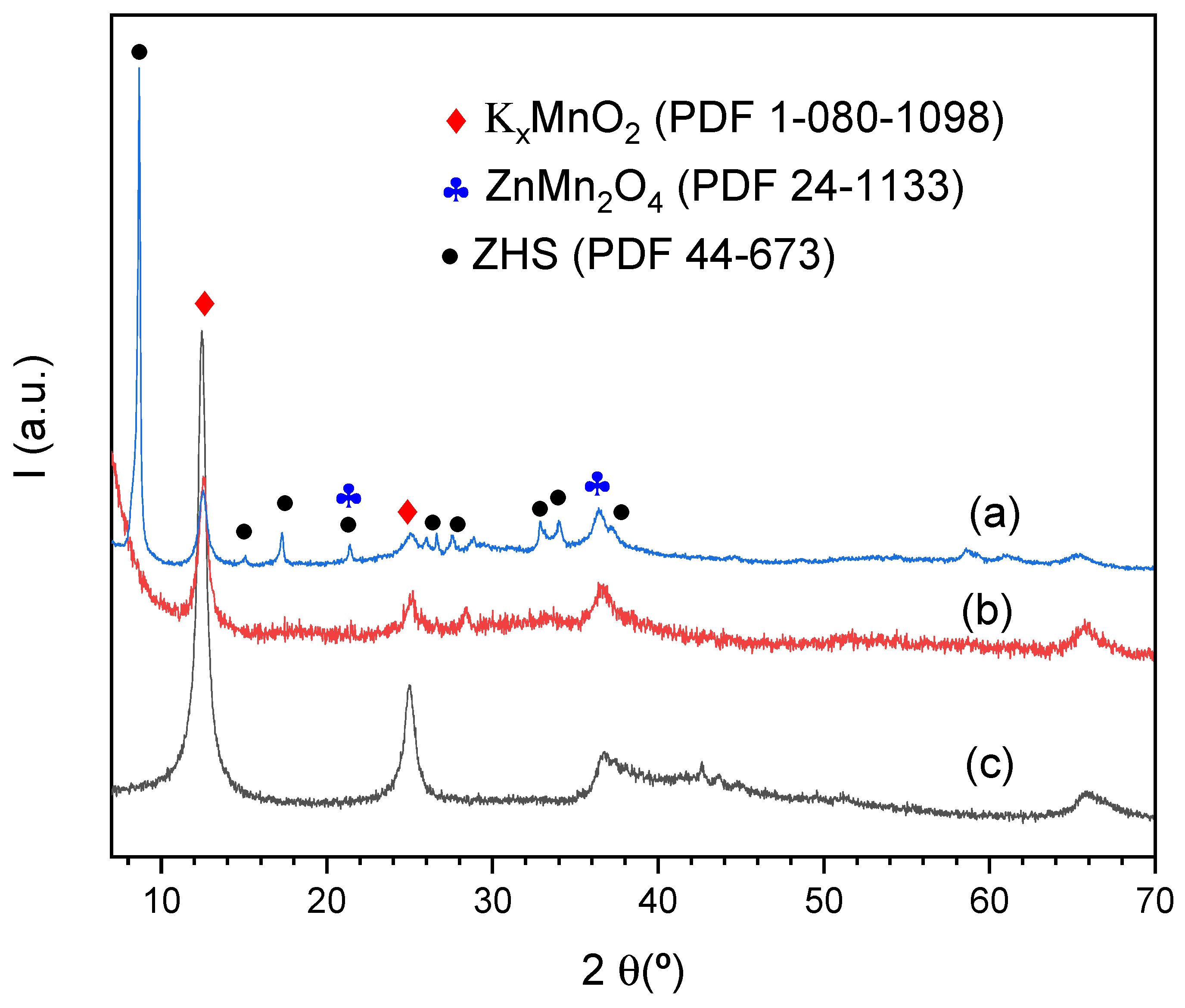
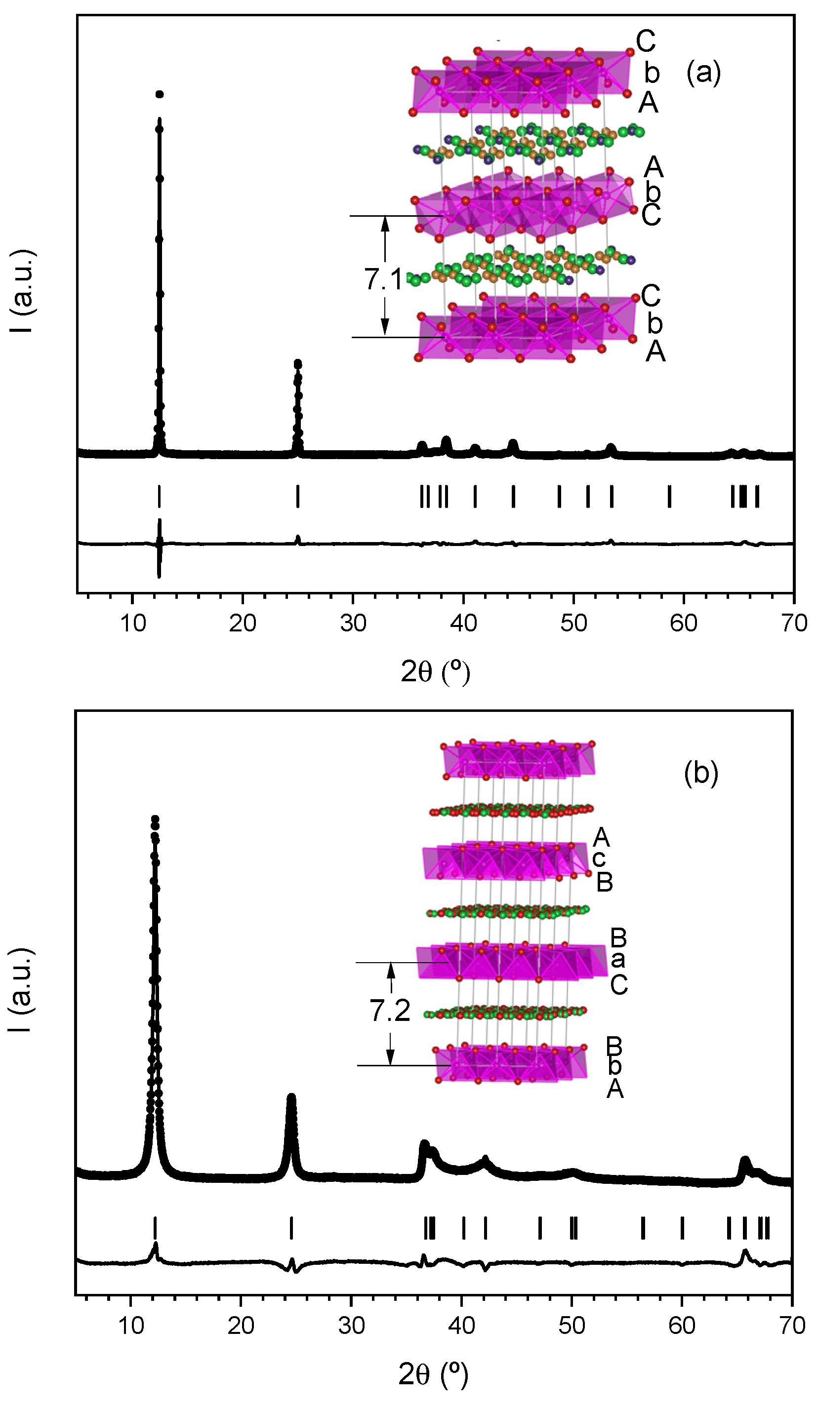
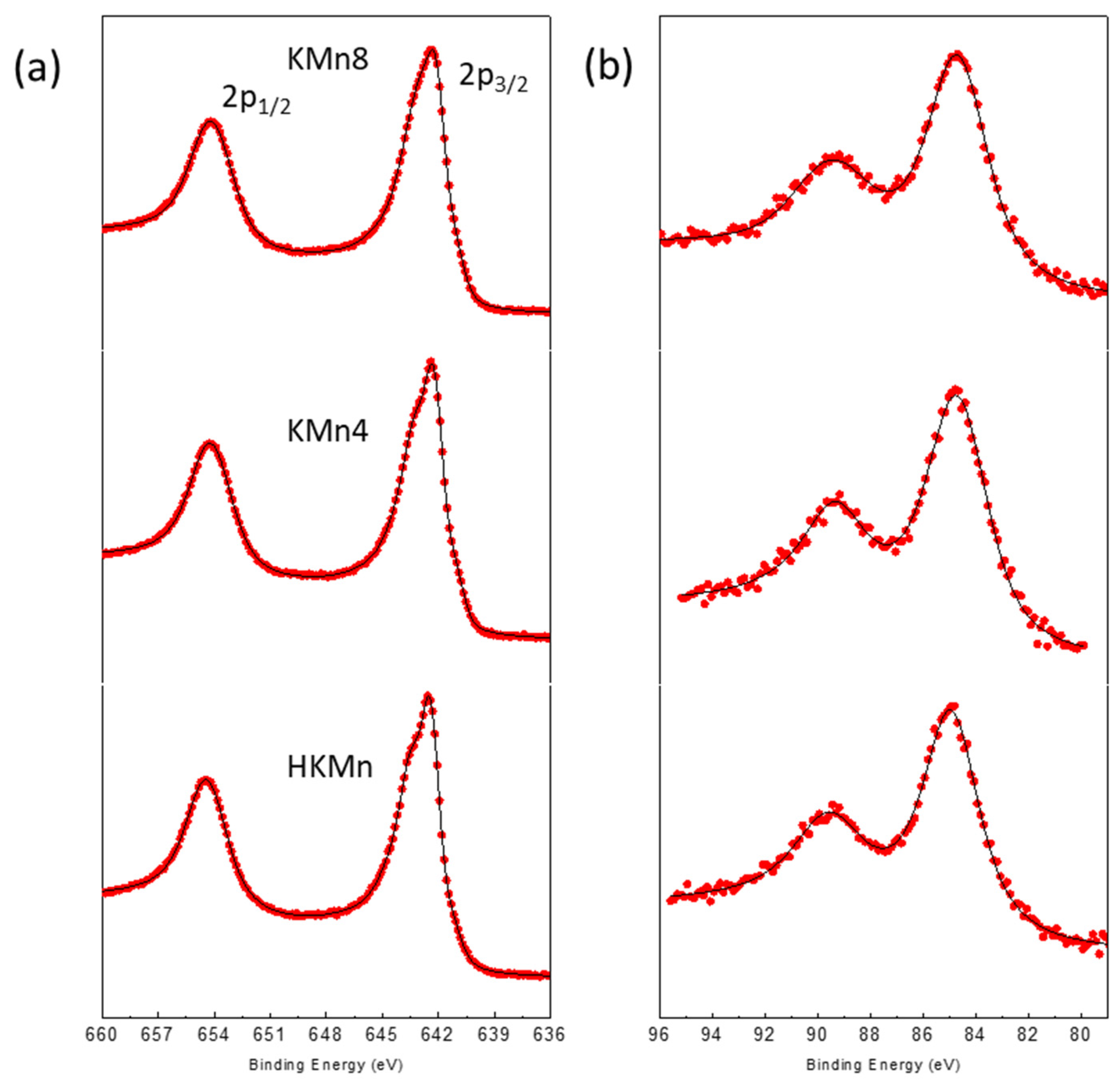
3.1. Materials Characterization

The XRD patterns of all samples are showed in Figure 1. Basal reflections at 12.5 and 25.1°, characteristic of the birnessite layered structure are observed for all samples. The reflections at higher 2θ-values exhibit some differences, indicative of structural dissimilarity between the samples. Thus, the wide maxima at 2θ~36.8° (2.44 Å) and 2θ~66.3° (1.41 Å) for KMn4 indicate a birnessite with turbostractic structure. In contrast, all reflections of the KMn8 could indexed to a hexagonal unit cell with a = 2.864(3) and c = 14.274(2) Å. On the other hand, HKMn maxima are coherent with a rhombohedral symmetry and cell parameters a = 2.846(9), 21.751(6) Å.
Table 1 gathers relevant crystallographic data obtained from Rietveld refinements of XRD data for KMn8 and HKMn. The corresponding profiles are shown in Figure 2. The structural models for both samples are also included (insets), evidencing the differences between them. Whereas the unit cell of KMn8 can be described as two-layer hexagonal (2H), the HKMn unit cell is three-layer hexagonal (3H). Thus, the close-packing notation for the 2H model is: AbC (water)-CbA (water)-AbC(water), and for the 3H model is: AbC(water)-CaB(water)-BcA(water), where A, B, C represent the oxygen positions and a, b, c refer to Mn positions [10,11]. The potassium ions and water molecules share the interlayer space as shown in Figure 2.
Vertical bars indicate Bragg permitted reflections. Insets show corresponding structural models: layers of MnO6 octahedra are represented in pink; water molecules and potassium cations are situated between layers.
EDX analysis indicated the presence of potassium in all the samples but in different concentration. Thus, examination of a representative number of crystals in each case led to mean different formulae. For KMn4 and KMn8, 0.3 K per formula was obtained. In the case of the HKMn sample, mean composition K0.03MnO2 was obtained, though in some crystals the obtained ratio was 0.3:1. Therefore, the samples prepared by different methods seem to retain different amounts of K in the interlayer space.
In addition, the thermogravimetric analysis in the 50–600 °C temperature range (Figure S1) displays three regions where decomposition takes place. The initial weight loss up to 120 °C can be associated with evaporation of surface-adsorbed water, whereas the second region, up to 200 °C, can be attributed to the dehydration of the interlayer water. Finally, the weight loss obtained when the material is heated above 250 °C, is usually associated with oxygen loss [12]. Furthermore, when the material is heated up to 600 °C, the HKMn is transformed into a 2 × 2 channel structure, as previously suggested [13]. Such changes are shown in the XRD diagram of the residue (Figure S1b,c). However, the XRD profiles of the KMn4 and KMn8 residues indicated a mixture of phases in which birnessite and a structure with 2 × 2 channel are present. Therefore, the amount of K between octahedra layers seems to be key in the thermal stability of birnessite structure. Therefore, in principle, hydrothermal method led to phases where the K amount is smaller than the obtained by thermal treatment.
In order to know the Mn oxidation state, XPS experiments were carried out. The Mn 2p core-level spectra for all compositions are shown in Figure 3 and the corresponding BE values are given in Table 2. The BEs of the Mn 2p1/2 and Mn 2p3/2 signals are given by the positions of the maxima of the main peaks. The asymmetric Mn 2p3/2 main peak is located at 642.3–642.6 eV with a (2p3/2–2p1/2) splitting of 11.8–11.9 eV. These values are closer to the BE of Mn 2p3/2 peaks reported for MnO2 (642.2 eV) [13].
Analysis of the 3s region is more useful to assess the oxidation state of manganese, due to mainly the exchange interaction between the 3s and 3d electrons [14,15]. The 3s splitting (Table 2) suggests that the samples have a Mn3+ and Mn4+ mixture. The values of Mn average oxidation state in KMn4, KMn8 and HKMn are gathered in Table 2 and were obtained as suggested by Beyreuther at al. [16] taking into account the doublet separation from Equation (1).
υMn = 9.67 − 1.27ΔE3s/eV
where υMn is the average oxidation state and ΔE3s splitting magnitude of 3s.
Therefore, taking into account the above results, the sample obtained at high temperature presents the highest amount of Mn(III). On the other hand, the sample prepared by hydrothermal method probably contains oxygen vacancies. As previously stated, the K amount in the formula of HKMn is considerably less than in the other samples [17].
The material morphology has a great influence on the electrochemical behaviour and therefore was analyzed by SEM and HRTEM. Some representative images are depicted in Figure 4. KMn8 (Figure 4c,d) consists predominantly of large micrometer-sized crystals exhibiting well-defined crystallographic faces whereas KMn4 (Figure 4a,b) exhibits cloud-like particles with diameters ranging between 175 and 260 nm. These large particles appear as aggregates of smaller individual particles with diameter close to 20 nm. On the other hand, HKMn (Figure 4e,f) present flower-like nanostructures, the individual nanoflowers are micro-sized and comprise a large number of thin nanosheets with a thickness of 15 nm. Moreover, striations along [1] orientation are clearly seen with spacings of ~7 Å in all samples.

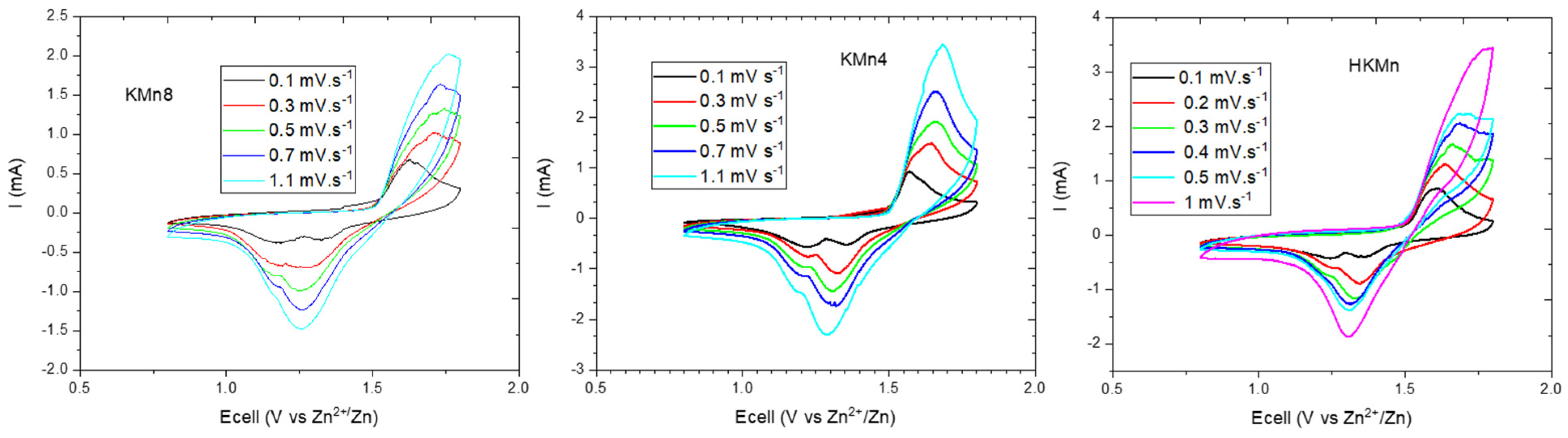
3.2. Electrochemical Behaviour

Figure 5 shows charge–discharge profiles of the three prepared samples at 30 mA g−1, between 1.8 and 0.8 V. The observed behaviour of the different charge-discharge profiles of the three samples, KMn4, KMn8, and HKMn, are similar to that reported previously in the literature for Zn-manganese oxide batteries [18]. Figure 5b gathers the efficiency and specific capacity values for all samples. It can be observed that at current density values of 30 mA g−1, all electrodes achieve capacity values lower than the theoretical one (308 mA h g−1). In the initial cycles, the following order in the capacity values is observed: KMn8 < KMn4 < HKMn. This result agrees with the average oxidation state obtained by XPS as well as the amount of K in the interlayer space commented above. Moreover, after 50 cycles, the specific capacity reached are 90, 105 and 110 mA h g−1, which mean capacity losses of 12, 14, and 32% for KMn8, KMn4, and HKMn, respectively.
Figure 6 shows the CV curves for assembled ZIBs using different currents for KMn8, KMn4 and HKMn. Their general aspect is similar to that previously found in other Mn-oxide ZIBs [19,20,21]. From the second cycle, two reduction peaks appear at 1.30 and 1.20 V. An oxidation peak at 1.55 V and a small shoulder at 1.65 V are also observed at lower speeds, i.e., 0.1–0.3 mV s−1. The voltage values of each peak are dependent on the scan rate and the sample morphology. Thus, at higher rates (0.7 and 1.1 mV s−1) the CV curves exhibit one strong cathodic peak located at 1.28 V and the other peak is now seen as a shoulder at 1.18 V and even disappear for the sample HKMn. In the same way the anodic peak at 1.55 V disappears and the shoulder at 1.65 hexagonal (2H) increases in intensity.
This gradual voltage change can be attributed to the ion diffusion [22]. At the discharge processes, as the CV rate increases the high-voltage peak remains present and even more intense (due to H+ insertion), while the low-voltage peak gradually decays (related to Zn2+ reaction).
In order to study the performance at high density current, the three samples were cycled at a rate of 300 mA g−1. Corresponding galvanostatic curves as well as capacity and efficiency versus cycle number are shown in Figure 7. In agreement with above statement, in the discharge stage the second plateau at this high speed is hardly seen for the three samples, which is related to Zn2+ insertion. It is only weakly appreciated in the HKMn sample, in which Zn2+ can be accumulated in the hollows between the leaves of the flower-like morphology. In addition, the capacity values obtained are in the same order than at low current density, i.e., KMn8 < KMn4 < HKMn. However, a different tendency is observed for capacity losses, which are practically negligible after 50 cycles.
The slight increase of capacity observed in Figure 5 and Figure 7 can be due to the Mn2+ present in the electrolyte, that can be related to deposition of MnO2 during the cycle as has been evidenced in the literature [23,24].
As has been suggested [25], the high voltage plateau in the discharging process (i.e., at 1.4 V) is due to a conversion reaction between MnO2 and H+ leading to MnOOH as intermediate, which is dissolved in acid medium through a disproportion. Therefore, the reductive reaction can be described as follows:
MnO2(s) + H+(aq) + 1e → MnOOH(s)
MnOOH(s) + H+(aq) → ½Mn2+(aq) + ½MnO2(s) + H2O(l).
In consequence, during the discharge process both dissolved Mn2+ and solid MnO2 will form.
Moreover, the H+ are consumed in this reaction. The above reaction (2) takes place due to that Zn2+ (aq) provides the hydrogen ions needed as follows:
[Zn(H2O)x]2+ → [Zn(H2O)x−1(OH)]+ + H+(aq)
At the same time, the precipitation of zinc hydroxide sulphate (ZHS) occurs.
4Zn2+(aq) + 6OH(aq) + SO42−(aq) + 5H2O(l) → Zn4(OH)6(SO4).5H2O(s)
XRD data was collected for KMn4 electrode after three cycles, and the XRD profiles of the sample discharged and charged are shown in Figure 8. In the XRD diagram corresponding to the discharged electrode, the peaks located at 12.3° and 24.8°(2θ) are characteristic of birnessite (PDF 1-080-1098). The other maxima that appear in the profile could be assigned to Zn4(OH)6(SO4)·5H2O (PDF-044-0673) phase (ZHS). However, at 2θ = 36.4° a new maximum appears, which corresponds to the most intense maximum of the ZnMn2O4 spinel. Therefore, the second plateau at 1.3 V can be related to the reaction between MnO2 and Zn2+ giving rise to the spinel-type compound:
2MnO2 + Zn2+ + 2e → ZnMn2O4
The XRD pattern of KMn4 electrode charged presents practically the same peaks as those observed in the original diffraction profiles. A slight difference can only be appreciated, the maximum at 2θ = 36.4° is slightly more intense, because of ZnMn2O4 phase which was obtained in the discharge process. Therefore, the second plateau at 1.3 V is only partially reversible. As the number of cycles increases, the amount of spinel phase increases, and this could explain the loss of capacity.
Therefore, the global reaction can be formulated as follows:
3/2MnO2(s) + 2H+(aq) + ½Zn2+(aq) + 2e → ½Mn2+(aq) + ½ZnMn2O4(s) + H2O(l)
Zn → Zn2+ + 2 e
3/2MnO2(s) + 2H+(aq) + Zn(s) → ½Mn2+(aq) + ½ZnMn2O4(s) + H2O(l) + ½Zn2+(aq)
On the contrary, in the charge process the reverse reaction takes place, i.e., the Mn2+ is oxidized to MnOOH, which in acid environment disproportionates leading to MnO2 birnessite:
Mn2+ + 2H2O → MnOOH + 3H+ + 1e
MnOOH + 1H+ → ½MnO2 + ½Mn2+ + H2O
Zn2+ + 2 e → Zn
Mn2+(aq) + 2H2O + Zn2+(aq) → MnO2(s) + 4H+(aq) + Zn(s)
Taking into account the mechanism indicated above, some conclusions could be established. First, charge–discharge process leads to the ZnMn2O4 spinel, which is created in the discharge process, but it is not reversibly transformed to MnO2 in the charge process. Thus, ZnMn2O4 seems to be present in charge stage (Figure 8). Therefore, the irreversibility obtained in aqueous Zn-ion batteries is related to the ZnMn2O4 compound [26], which is obtained in the second plateau, i.e., at low potential (1.3 V). At low density current, 30 mA g−1, both plateaux appear and when the number of cycles grows up, the second plateau becomes smaller. The order in the length of this plateau is as follows: KMn8 < KMn4 < HKMn. The capacity loss for these materials goes on the same sequence. Finally, this plateau is hardly seen at high density current (300 mA g−1), then after 50 cycles the loss capacity is practically negligible.
Moreover, this result has been supported by XRD data (Figure 9) of the HKMn electrode cycled at 30 mA g−1 rate until the battery stopped working. All maxima that appear were identified as the phase ZnMn2O4, neither maximum of ZHS or birnesite-type structure was observed.

4. Conclusions

Manganese oxides with birnessite-type structure have been synthetized by two different methods: thermal treatment and hydrothermal method. Both syntheses were carried out from a low-cost material (KMnO4). The thermal decomposition at temperatures of 400 and 800 °C made it possible to obtain KxMnO2 birnessite with different crystallinity degree. Moreover, XPS data indicated that the sample obtained at higher temperature presents on the surface a lower amount of Mn4+ that the other derivatives. In relation to structure characterization obtained by powder X-ray diffraction, KMn4 presents a turbostractic structure whereas KMn8 and HKMn have hexagonal and rhombohedral symmetries, respectively. The morphologies obtained by SEM and HRTEM for KMn8, KMn4, and HKMn samples shown well-defined crystals, cloud-like particles with aggregates and a flower-like nanostructure, respectively.
The sample obtained at high temperature (KMn8) exhibits a lower oxidation state as well as a denser morphology, both characteristics are related to the obtained low-capacity value. The Zn2+ insertion is very small at low density current and negligible at high density current, which seems to be a key factor of capacity retention. On the other hand, in the samples obtained at low temperature (KMn4) or by means of hydrothermal method, Mn cations have an oxidation state close to 4 and their morphologies allow Zinc ions to have a better accessibility towards birnessite-type structure. The incorporation of Zn2+ in the structure gives rise to the ZnMn2O4 spinel and this process implies that some links must be broken, and at the same time others must be set up. When the spinel-like ZnMn2O4 structure is obtained capacity retention reduces, which is favorable at low speeds. In consequence, the best result is obtained when the sample presents a great accessibility and high density current where ZnMn2O4 compound would not have enough time to form.

Supplementary Materials

The following are available online at https://www.mdpi.com/article/10.3390/app12031176/s1, Figure S1: (a) Thermogravimetric analysis under N2 for all samples. (b) XRD profile of KMn8 residue, the maxima were assigned to a mixture of phases: birnessite and K1.33Mn8O16; (c) XRD profile of the HKMn residue, the maxima were indexed to K1.33Mn8O16. Table S1. Weight loss from ATG data (%) and structural formulas for birnessite-type material obtained from EDX and ATG data.

Author Contributions

Conceptualization, M.L.L. and E.R.-C.; methodology, I.Á.-S.; validation, M.L.L., E.R.-C. and I.Á.-S.; investigation, P.A. and D.A.G. and E.R.-A.; writing—original draft preparation, M.L.L. and E.R.-C.; writing—review and editing, M.L.L., I.Á.-S. and E.R.-C. visualization, P.A.; supervision, M.L.L.; project administration, M.L.L. funding acquisition, I.Á.-S. All authors have read and agreed to the published version of the manuscript.

Funding

This work has been supported by the Spanish Ministry of Economy and Competitiveness (MINECO) through project MAT2017-84118-C2-2-R and Spanish Ministry of Science Innovation and Universities trough project RTI2018-099668-B-C22, which have not played any role in any aspect regarding the study design, the collection, analysis and interpretation of data, the writing of the report, or the decision to submit the article for publication.

Institutional Review Board Statement

Not applicable.

Informed Consent Statement

Not applicable.

Data Availability Statement

The following are available on line Figure S1. (a) Thermogravimetric analysis under N2 for all samples. (b) XRD profile of KMn8 residue, the maxima were assigned to a mixture of phases: birnessite and K1.33Mn8O16; (c) XRD profile of the HKMn residue, the maxima were indexed to K1.33Mn8O16. Table S1. Weight loss from ATG data (%) and Structural formulas for birnessite-type material obtained from EDX and ATG data.

Acknowledgments

The authors would like to thank Imerys Graphite & Carbon who kindly provided the carbon black. In addition, authors are grateful to the CAI centers of UCM (XRD and electron microscopy).

Conflicts of Interest

The authors declare no conflict of interest. The funders had no role in the design of the study; in the collection, analyses, or interpretation of data; in the writing of the manuscript, or in the decision to publish the results.

References

  1. Dehghani-Sanij, A.R.; Tharumalingam, E.; Dusseault, M.B.; Fraser, R. Study of energy storage systems and environmental challenges of batteries. Renew. Sustain. Energy Rev. 2019, 104, 192–208. [Google Scholar] [CrossRef]
  2. Chao, D.; Zhou, W.; Xie, F.; Ye, C.; Li, H.; Jaroniec, M.; Qiao, S.-Z. Roadmap for advanced aqueous batteries: From design of materials to applications. Sci. Adv. 2020, 6, eaba4098. [Google Scholar] [CrossRef] [PubMed]
  3. Alfaruqi, M.H.; Mathew, V.; Gim, J.; Kim, S.; Song, J.; Baboo, J.P.; Choi, S.H.; Kim, J. Electrochemically Induced Structural Transformation in a γ-MnO2 Cathode of a High Capacity Zinc-Ion Battery System. Chem. Mater. 2015, 27, 3609–3620. [Google Scholar] [CrossRef]
  4. Blanc, L.E.; Kundu, D.; Nazar, L.F. Scientific Challenges for the Implementation of Zn-Ion Batteries. Joule 2020, 4, 771–799. [Google Scholar] [CrossRef]
  5. Li, B.; Zhang, X.; Wang, T.; He, Z.; Lu, B.; Liang, S.; Zhou, J. Interfacial Engineering Strategy for High-Performance Zn Metal Anodes. Nano-Micro Lett. 2022, 14, 6. [Google Scholar] [CrossRef]
  6. Tang, F.; Gao, J.; Ruan, Q.; Wu, X.; Wu, X.; Zhang, T.; Liu, Z.; Xiang, Y.; He, Z.; Wu, X. Graphene-Wrapped MnO/C Composites by MOFs-Derived as Cathode Material for Aqueous Zinc ion Batteries. Electrochim. Acta 2020, 353, 136570. [Google Scholar] [CrossRef]
  7. Canepa, P.; Gautam, G.S.; Hannah, D.C.; Malik, R.; Liu, M.; Gallagher, K.G.; Persson, K.A.; Ceder, G. Odyssey of Multivalent Cathode Materials: Open Questions and Future Challenges. Chem. Rev. 2017, 117, 4287–4341. [Google Scholar] [CrossRef]
  8. Rietveld, H.M. A profile refinement method for nuclear and magnetic structures. J. Appl. Crystallogr. 1969, 2, 65. [Google Scholar] [CrossRef]
  9. Rodriguez-Carvajal, J. Recent advances in magnetic structure determination by neutron powder diffraction. Phys. B Condens. Matter 1993, 192, 55. [Google Scholar] [CrossRef]
  10. Gaillot, A.-C.; Flot, D.; Drits, V.A.; Manceau, A.; Burghammer, M.; Lanson, B. Structure of Synthetic K-rich Birnessite Obtained by High-Temperature Decomposition of KMnO4. I. Two-Layer Polytype from 800 °C Experiment. Chem. Mater. 2003, 15, 4666–4678. [Google Scholar] [CrossRef] [Green Version]
  11. Gaillot, A.-C.; Drits, V.A.; Plancüon, A.; Lanson, B. Structure of Synthetic K-Rich Birnessites Obtained by High-Temperature Decomposition of KMnO4. 2. Phase and Structural Heterogeneities. Chem. Mater. 2004, 16, 1890–1905. [Google Scholar] [CrossRef] [Green Version]
  12. Arias, N.P.; Becerra, M.E.; Giraldo, O. Structural and Electrical Studies for Birnessite-Type Materials Synthesized by Solid-State Reactions. Nanomaterials 2019, 9, 1156. [Google Scholar] [CrossRef] [PubMed] [Green Version]
  13. Becerra, M.E.; Arias, N.P.; Giraldo, O.H.; López, F.E.; Gómez, M.J.I.; Bueno, A. Soot combustion manganese catalysts prepared by thermal decomposition of KMnO4. Appl. Catal. B Environ. 2011, 102, 260–266. [Google Scholar] [CrossRef]
  14. Oku, M.; Hirokawa, K.; Ikeda, S. X-ray photoelectron spectroscopy of manganese-Oxygen systems. J. Electron. Spectrosc. Relat. Phenom. 1975, 7, 465–473. [Google Scholar] [CrossRef]
  15. Huynh, M.; Shi, C.; Billinge, S.J.L.; Nocera, D.G. Nature of Activated Manganese Oxide for Oxygen Evolution. J. Am. Chem. Soc. 2015, 137, 14887–14904. [Google Scholar] [CrossRef]
  16. Beyreuther, E.; Grafström, S.; Eng, L.M.; Thiele, C.; Dörr, K. XPS investigation of Mn valence in lanthanum manganite thin films under variation of oxygen content. Phys. Rev. B 2006, 73, 155425. [Google Scholar] [CrossRef]
  17. Cao, R.; Li, L.; Zhang, P.; Gao, L.; Rong, S. Regulating oxygen vacancies in ultrathin δ-MnO2 nanosheets with superior activity for gaseous ozone decomposition. Environ. Sci. Nano 2021, 8, 1628–1641. [Google Scholar] [CrossRef]
  18. Zhang, W.; Zhai, X.; Zhang, Y.; Wei, H.; Ma, J.; Wang, J.; Liang, L.; Liu, Y.; Wang, G.; Ren, F.; et al. Application of Manganese-Based Materials in Aqueous Rechargeable Zinc-Ion Batteries. Front. Energy Res. 2020, 8, 195. [Google Scholar] [CrossRef]
  19. Hao, J.; Mou, J.; Zhang, J.; Dong, L.; Liu, W.; Xu, C.; Kang, F. Electrochemically induced spinel-layered phase transition of Mn3O4 in high performance neutral aqueous rechargeable zinc battery. Electrochim. Acta 2018, 259, 170. [Google Scholar] [CrossRef]
  20. Chen, L.; Yang, Z.; Cui, F.; Meng, J.; Jiang, Y.; Long, J.; Zeng, X. Ultrathin MnO2 nanoflakes grown on N-doped hollow carbon spheres for high-performance aqueous zinc ion batteries. Mater. Chem. Front. 2020, 4, 213. [Google Scholar]
  21. Yang, S.; Zhang, M.; Wu, X.; Wu, X.; Li, F.Z.Y.; Duan, S.; Fan, D.; Yang, Y.; Wu, X. The excellent electrochemical performances of ZnMn2O4/Mn2O3: The composite cathode material for potential aqueous zinc ion batteries. J. Electroanal. Chem. 2019, 832, 69. [Google Scholar] [CrossRef]
  22. Fan, X.; Zhu, Y.; Luo, C.; Suo, L.; Lin, Y.; Gao, T.; Xu, K.; Wang, C. Pomegranate-Structured Conversion-Reaction Cathode with a Built-in Li Source for High-Energy Li-Ion Batteries. ACS Nano 2016, 10, 5567. [Google Scholar] [CrossRef] [PubMed]
  23. Álvarez-Serrano, I.; Almodóvar, P.; Giraldo, D.A.; Llopis, F.; Solsona, B.; López, M.L. Stable Manganese-Oxide Composites as Cathodes for Zn-Ion Batteries: Interface Activation from In Situ Layer Electrochemical Deposition under 2 V. Adv. Mater. Interfaces 2021, 2101924. [Google Scholar] [CrossRef]
  24. Qiu, C.; Zhu, X.; Xue, L.; Ni, M.; Zhao, Y.; Liu, B.; Xia, H. The function of Mn2+ additive in aqueous electrolyte for Zn/δ-MnO2 battery. Electrochim. Acta 2020, 351, 136445. [Google Scholar] [CrossRef]
  25. Yang, J.; Cao, J.; Peng, Y.; Yang, W.; Barg, S.; Liu, Z.; Kinloch, I.A.; Bissett, M.A.; Dryfe, R.A.W. Unravelling the Mechanism of Rechargeable Aqueous Zn–MnO2 Batteries: Implementation of Charging Process by Electrodeposition of MnO2. ChemSusChem 2020, 13, 4103–4110. [Google Scholar] [CrossRef] [PubMed]
  26. Alfaruqi, M.H.; Islam, S.; Putro, D.Y.; Mathew, V.; Kim, S.; Jo, J.; Kim, S.; Sun, Y.-K.; Kim, K.; Kim, J. Structural transformation andelectrochemical study of layered MnO2 in rechargeable aqueous zinc-ion battery. Electrochim. Acta 2018, 276, 1–11. [Google Scholar] [CrossRef]
Figure 1. XRD patterns of (a) KMn4, (b) KMn8 and (c) HKMn.
Applsci 12 01176 g001
Figure 2. Calculated (line), experimental (dot) and difference (bottom line) Rietveld profiles for (a) KMn8 and (b) HKMn.
Applsci 12 01176 g002
Figure 3. XPS spectra of KMn8, KMn4 and HKMn: (a) Mn 2p region and (b) Mn 3s region.
Applsci 12 01176 g003
Figure 4. SEM (left) and HRTEM (right) representative images of (a,b) KMn4, (c,d) KMn8, and (e,f) HKMn.
Applsci 12 01176 g004
Figure 5. (a) Charge–discharge profiles at 30 mA g−1 and (b) specific capacity and efficiency for KMn8, KMn4 and HKMn during 50 cycles.
Applsci 12 01176 g005
Figure 6. Cyclic voltammetry curves for KMn8, KMn4, and HKMn.
Applsci 12 01176 g006
Figure 7. (a) Charge–discharge profiles at 300 mA g−1 and (b) Specific capacity and efficiency for KMn8, KMn4 and HKMn during 50 cycles.
Applsci 12 01176 g007
Figure 8. XRD profile “ex situ” of KMn4 after three cycles (a) discharged (b) charged (c) KMn4 profile with comparative purpose.
Applsci 12 01176 g008
Figure 9. X-ray diffraction pattern “ex situ” of HKMn post-mortem.
Applsci 12 01176 g009
Table 1. Crystallographic data of KMn8 and HKMn.
PhaseKMn8HKMn
Space groupP 63/mmcR -3m
a (Å)2.864 (5)2.846 (9)
c (Å)14.274 (2)21.751 (6)
Rp19.315.3
Rwp18.216.1
RB9.14.7
Table 2. Binding energies (eV) for Mn 2p and Mn 3s core level components of XPS spectra of the samples.
Sample Mn 2p Mn 3s
2p1/22p3/2Δ(2p1/2–2p3/2)3s(1)3s(2)Δ(3s(1)–3s(2))υMn
KMn4654.2642.411.889.484.74.73.8
KMn8654.2642.311.989.384.74.63.6
HKMn654.4642.611.889.684.94.73.8
Publisher’s Note: MDPI stays neutral with regard to jurisdictional claims in published maps and institutional affiliations.

