Article

Simple Lossless Inductive Snubbers-Assisted Series Load Resonant Inverter Operating under ZCS-PDM Scheme for High-Frequency Induction Heating Fixed Roller

1
Department of Electrical Engineering, Faculty of Science and Engineering, Kyushu Sangyo University, 2-3-1 Matsukadai, Higashi-ku, Fukuoka 813-8503, Japan
2
Department of Electrical Engineering, School of Engineering and Technology, Walailak University, 222 Thaiburi, Thasala District, Nakhon Si Thammarat 80160, Thailand
3
Renewable Energy Group, Faculty of Engineering and Science, University of Agder, Postboks 422, 4604 Kristiansand, Norway
4
School of Science, Computing and Engineering Technologies, Swinburne University of Technology, P.O. Box 218, Hawthorn, VIC 3122, Australia
5
Power Electronics and Renewable Energy Research Laboratory, Department of Electrical Engineering, University of Malaya, Kuala Lumpur 50603, Malaysia
6
Center of Research Excellence in Renewable Energy and Power Systems, King Abdulaziz University, Jeddah 21589, Saudi Arabia
*
Author to whom correspondence should be addressed.
Appl. Sci. 2022, 12(3), 1122; https://doi.org/10.3390/app12031122
Submission received: 27 October 2021 / Revised: 4 January 2022 / Accepted: 18 January 2022 / Published: 21 January 2022
(This article belongs to the Special Issue Intelligent Sensors and Actuators)

Abstract

:
This paper presents a high-frequency pulse-density-modulated (PDM) soft-switching series load resonant inverter for use in induction heating (IH) fixed roller applications, which is used in copy and printing machines. The proposed simple high-frequency resonant inverter uses an asymmetrical pulse pattern PDM control scheme to achieve complete zero-current soft-switching commutations over a wide output range of input power regulation. Additionally, when the printer toner requires operation in very light load conditions, this causes difficulty in achieving zero-voltage or zero-current soft-switching operations in the IH high-frequency resonant inverters with pulse frequency modulation or pulse width modulation control schemes. The proposed resonant inverter demonstrates the capability to accomplish highly efficient power conversions. In this work, a fixed roller for printing machines is developed for doing experiments to verify the efficiency of the proposed circuit topology and its PDM control schemes. The inverter’s steady-state and transient operating principles are analyzed based on the proposed control strategy at a high-frequency PDM. Operating conditions such as power loss analysis, power conversion efficiency and temperature rise characteristics of the proposed inverter are presented and analyzed through experimental results. Finally, from a practical viewpoint, a comparative study of a conventional halogen lamp heater and the proposed IH fixed roller is deliberated.

1. Introduction

In recent years, power-electronics-based power conditioning devices have been used in the area of induction heating (IH) technologies. IH technologies are energy efficient [1], and they are used extensively for heating applications (e.g., cooking stoves, etc.) [2,3]. IH is also used in office automation appliances. IH systems are fundamentally composed of electrical power converter circuits, digital control schemes and magnetic components [4]. There are different types of circuit topology for IH applications. Most of them are categorized as full-bridge inverters [5,6], half-bridge inverters [7,8,9,10,11], resonant single-ended inverters [12] and inverters employing active voltage clamping [13]. The half-bridge inverters are widely used for IH applications due to their cost effectiveness and robustness. Additionally, the techniques of zero-voltage and zero-current soft-switching (ZVS, ZCS) are employed in the circuit topologies, resulting in the reduction of losses during switching [8,14].
Generally, pulse modulation methodology is employed in the high-frequency inverter to achieve output power regulation for IH application. Mainly, there are three types of modulations, which are as follows: (i) pulse frequency modulation (PFM) [15,16], (ii) pulse width modulation (PWM) [17] and (iii) pulse density modulation (PDM) [18,19,20,21]. The simplest modulation technique is PFM. Hence, it is the most widely employed with a single-switched inverter, and a variable switching frequency is used for controlling the injected currents from the voltage power source. However, the variation of the switching frequency for control of the IH load parameters is a disadvantage for domestic applications. As a result, the inverters with PFM-controlled schemes emit some annoying acoustic sounds [22]. By contrast, the sound of inverters with PWM-controlled schemes is quieter. However, the power conversion efficiency of PWM inverters is lower when they are operated at low power output due to soft-switching commutations, which are likely to fail [23].
In order to improve the functionality and efficiency of both conventional PFM and PWM high-frequency resonant inverters, PDM control schemes have been widely used in recent years. Most early works on implementing PDM control schemes in high-frequency resonant inverters are usually for industrial applications [24]. These inverters are proven to be effective because they are operated with fixed operating frequency, which guarantees the achievement of soft-switching operations at a wider range of output power. Generally, the power requirement of domestic IH applications is less than 2 kW, though this needs further investigation with different control topologies. There are some efforts towards implementing PDM into various modulation control schemes so that high-frequency resonant inverters can be operated in dual modes with the PDM operations at low-output-power regulations [18,25,26,27,28]. Such techniques significantly improve the efficiency of high-frequency resonant inverters. As a result, ZCS and ZVS operations are used at a wider range of output power, especially when power output is lower. An effort to improve high-frequency resonant inverter operation at low power output uses the discontinuous mode to establish the soft-switching commutations at a lower power output range [7]. It demonstrates improvement in the efficiency of general domestic IH applications at a 1.5 kW power range. However, the control schemes of discontinuous current mode are similar to PDM, and they need the switching frequency to be changed regularly in accordance with the required output power. They may result in the failures of soft-switching operations at a very low power range.
Typically, in conventional copy and printing machines, halogen lamp heater radiant heat is used for the process of toner fixing. However, it is not an effective method due to a low conversion efficiency and heat response since it uses an indirect heating process. However, these disadvantages can be overcome using the IH process, with the benefits of the eddy currents and magnetic hysteresis. The IH process is obviously a direct heat induction with accurate control in its power requirement. Additionally, printing and copy machine operation requires a wide range of power regulation, as they are required to undergo rated power operations ranging from low output (as low as their stand-by mode) up to their maximum power output.
The key focus of this paper is to use IH rollers in printing and copy machines by applying a PDM-controlled inverter using high-frequency series load resonant soft-switching technology. The PDM control scheme of this circuit topology is operated under the asymmetrical pattern of pulses. The symmetrical PDM pattern is used in high-power applications [24]. The extremely low-power-output operations, such as in the stand-by mode of a copy machine, can be realized using an asymmetrical PDM pattern. Additionally, this paper presents an interesting circuit topology, using only one auxiliary resonant capacitor with the aids of two separated auxiliary resonant inductors. The presented circuit topology, with the help of fixed-switching operating frequency and the PDM control scheme, enhances the combinations of ZVS and ZCS operations. The circuits of power regulation and operational characteristics are analyzed based on the developed experimental setup and obtained results. Additionally, loss calculations and power conversion efficiencies are analyzed. Lastly, a conventional halogen lamp heater and the proposed IH fixed roller application are presented from a practical viewpoint.

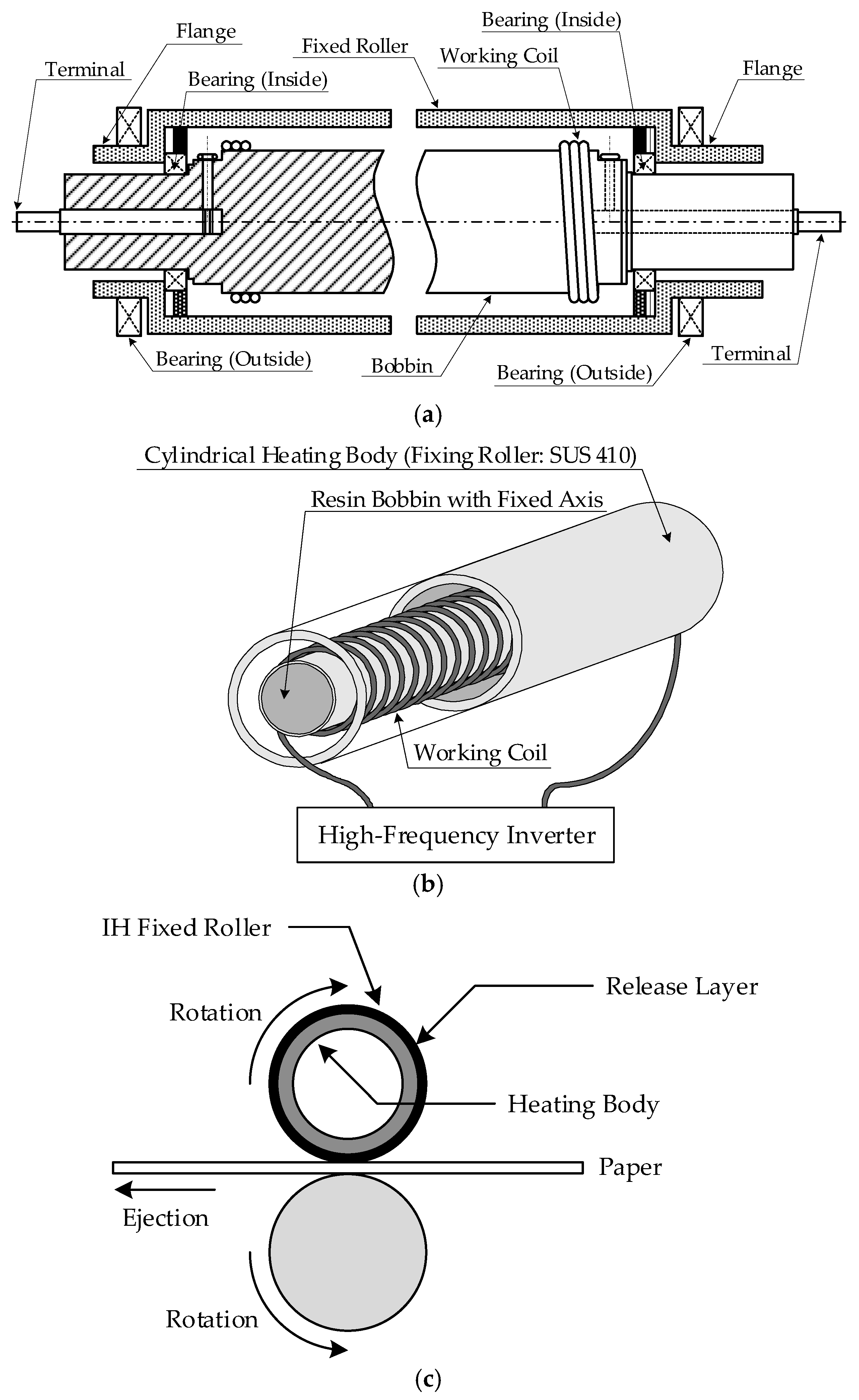
2. Schematic of Induction Heating Fixed Roller and Its Equivalent Circuit

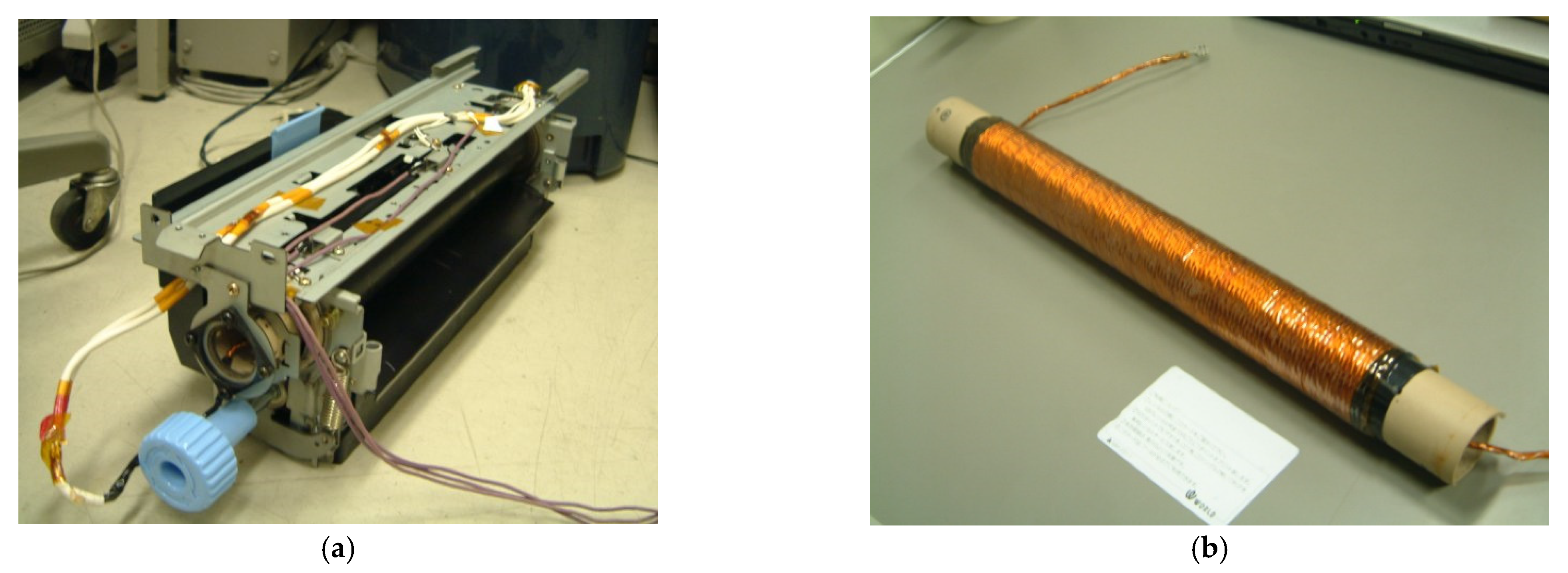
2.1. Schematic Structure of Induction Heating Fixed Roller

An IH-based fixed roller for printing and copy machines is specially developed in a laboratory. This fixed roller uses IH and directly heats the external roller to the printing toner. This directly heated IH-based fixed roller is highly efficient in comparison to indirect radiant heat generated by the use of a halogen lamp, which is conventionally used. Further, an IH fixed roller’s surface temperature (160–200 °C) can be easily controlled. Fixed roller structure is shown in Figure 1a,b. The IH fixed roller is composed of a rolling drum with a heating coil wound around an internal resin bobbin. Figure 1c illustrates an IH fixed roller toner fixing process. Surfaces of an aluminum or iron heating body have a release layer. This layer is composed of either a soft type with an elastic body or a hard type with a resin. Full-color printing and copy uses the soft type, and mono-color uses the hard type. Magnetic stainless steel (SUS 410) is used in the heating body. Carbon ceramic or an alloy of titanium can also be used.

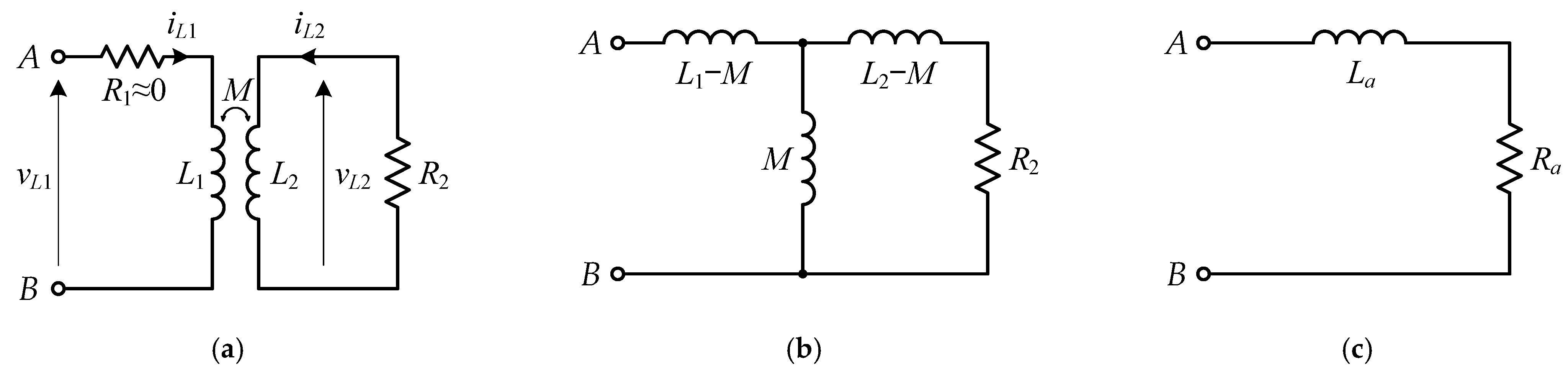
2.2. Transformer Circuit Model for IH Load

The conventional R-L series or parallel model for IH applications uses equivalent impedance models. However, the practical model of IH applications requires distorted voltage and current to be applied to the IH load in case of operation with a high-frequency inverter. In order to analyze and simulate the characteristics of a high-frequency inverter, including IH load, an analytical model of the real IH load is required.
Time-varying load parameters are used in IH load applications requiring high temperatures. Applications such as thermal processing, heat treatment and metal melting use these time-varying load parameters. However, in the case of applications for low temperatures, load parameters vary slowly around an operating point. Hence, in this work, load parameters are considered to be constant. To provide an accurate representation of the IH load, the transformer model is used for simulation analysis, as shown in Figure 2a. The model of the transformer has self-inductances L1 and L2, the winding resistance R1 and the effective resistance R2, considering the skin effect of the heating object. The equivalent circuit parameters of Figure 2a are assumed to be constant as the quasi-steady state. Resistance R1 is small enough and uses the litz wire, which reduces the skin effect, and therefore, it is ignored. Resistance R2 is based on the current penetration depth, and the skin effect is related to the high-frequency inverter switching frequency.
The state equation for the equivalent circuit of the IH load in Figure 2a is expressed as follows:
L 1 d i L 1 d t + M d i L 2 d t = v L 1 M d i L 1 d t + L 2 d i L 2 d t + R 2 i L 2 = 0
Magnetic fluxes φ1 and φ2 are expressed as follows:
φ 1 = L 1 i L 1 φ 2 = M i L 2
By substituting φ1 and φ2 from Equation (2) into Equation (1), the following equation can be obtained:
d φ 1 d t + d φ 2 d t = v L 1 k 2 d φ 1 d t + d φ 2 d t + φ 2 τ = 0
where
τ = L 2 R 2
k = M L 1 L 2
By solving Equation (3), the IH load parameters can be represented by the electromagnetic coefficient of coupling k and time constant τ of the high-frequency inverter. This inverter operation for an IH load is independent of the values of R2 and L2 if these values’ ratio is constant for a certain value of k. The electromagnetic coupling degree with the heating coil and the heating body is represented by the parameter k. The IH load time constant is represented by parameter τ. The L1 value is the heating coil self-inductance as measured on the transformer model primary side, with the secondary side open-circuited. Further, this L1 value equals the heating coil self-inductance with a heating object with zero conductivity and a nonmagnetic heating body under the no-load condition using materials such as stainless steel or aluminium.

2.3. Theoretical Analysis of IH Load Parameters

This section describes the theoretical analysis of the parameters τ and k derived by the equivalent circuit expression on the above and actual measurement of these parameters. The transformer equivalent circuit model can be illustrated in Figure 2b. We can only measure the self-inductance L1, the equivalent inductance La and the equivalent resistance Ra, as shown in Figure 2c.
From Figure 2b, the equivalent impedance of terminal A-B is expressed by the following equation:
Z A B = j ω L 1 M + j ω M R 2 + j ω L 2 M j ω M + R 2 + j ω L 2 M = ω 2 M 2 R 2 R 2 2 + ω 2 L 2 2 + j ω L 1 R 2 2 + ω 2 L 2 L 1 L 2 M 2 R 2 2 + ω 2 L 2 2
where ω is angular frequency.
The impedance of the L-R series equivalent circuit model in Figure 2c is expressed as follows:
ZAB = Ra + jωLa
Because the real part and the imaginary part of Equations (6) and (7) are equal, the equivalent resistance Ra and inductance La can be expressed as follows:
R a = ω 2 M 2 R 2 R 2 2 + ω 2 L 2 2 L a = L 1 R 2 2 + ω 2 L 2 L 1 L 2 M 2 R 2 2 + ω 2 L 2 2
L1La can be calculated as follows:
L 1 L a = ω 2 L 2 M 2 R 2 2 + ω 2 L 2 2
From Equations (8) and (9), τ and k can be described with L1, La and Ra as follows:
τ = L 2 R 2 = L 2 R 2 × ω 2 M 2 R 2 2 + ω 2 L 2 2 ω 2 M 2 R 2 2 + ω 2 L 2 2 = ω 2 L 2 M 2 R 2 2 + ω 2 L 2 2 ω 2 M 2 R 2 R 2 2 + ω 2 L 2 2 = L 1 L a R a
k = M L 1 L 2 = M 2 L 1 L 2 = M 2 L 1 L 2 × ω 4 M 2 ( R 2 2 + ω 2 L 2 2 ) ( R 2 2 + ω 2 L 2 2 ) 2 ω 4 M 2 ( R 2 2 + ω 2 L 2 2 ) ( R 2 2 + ω 2 L 2 2 ) 2 = R a 2 + ω 2 ( L 1 L a ) 2 ω 2 L 1 ( L 1 L a )
As a result, IH load can be expressed by three parameters, L1, τ and k.

3. ZCS Series Load Resonant High-Frequency Inverter Employing PDM Control

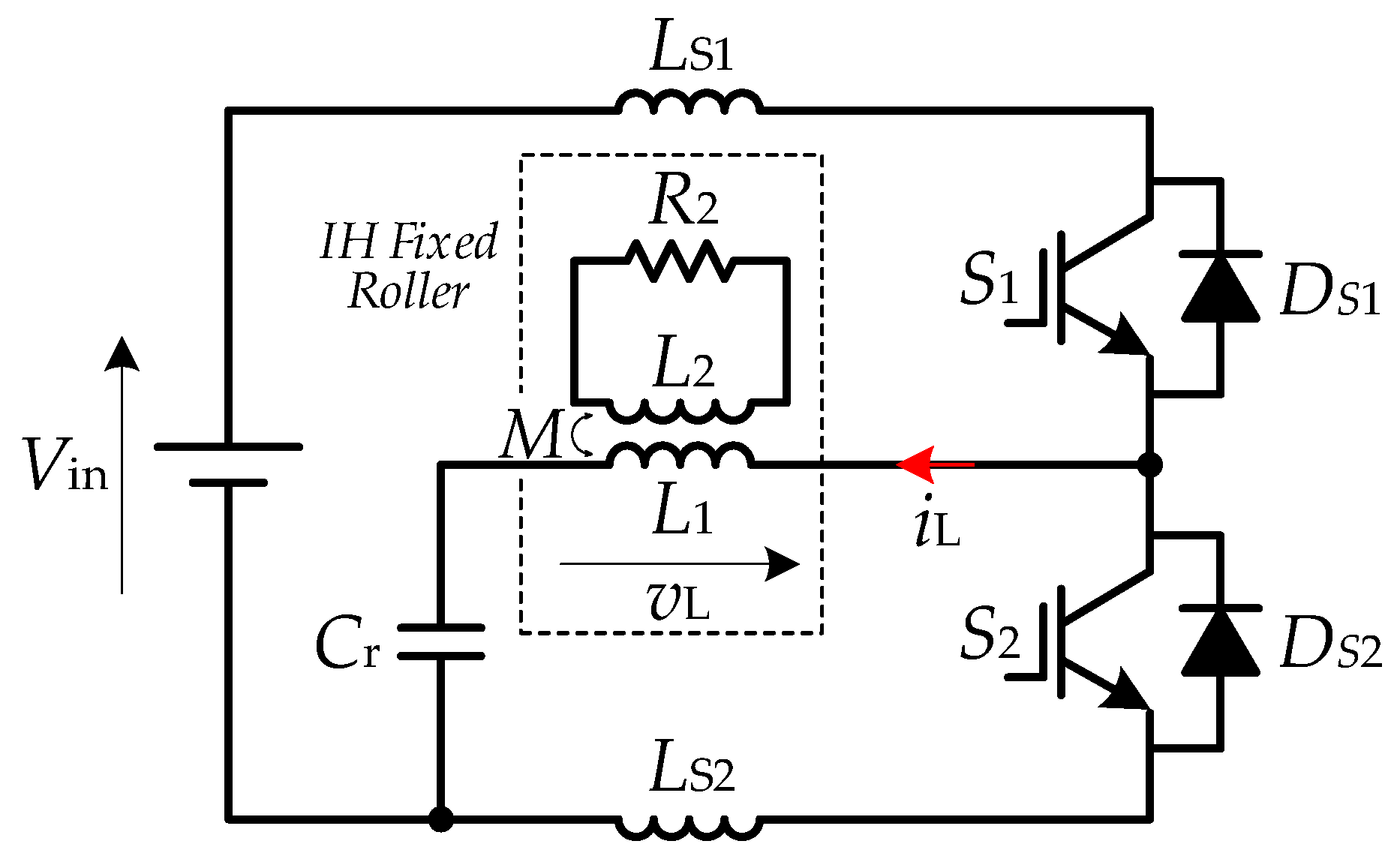
3.1. Circuit Description

A series load resonant high-frequency soft-switching inverter employing PDM control for an IH fixed roller is shown in Figure 3. It is composed of S1 and S2 active power switches; Cr, a resonant capacitor in series with IH load; and LS2 and LS1, two ZCS-assisted snubber inductors, which are in series with S1 and S2, respectively.

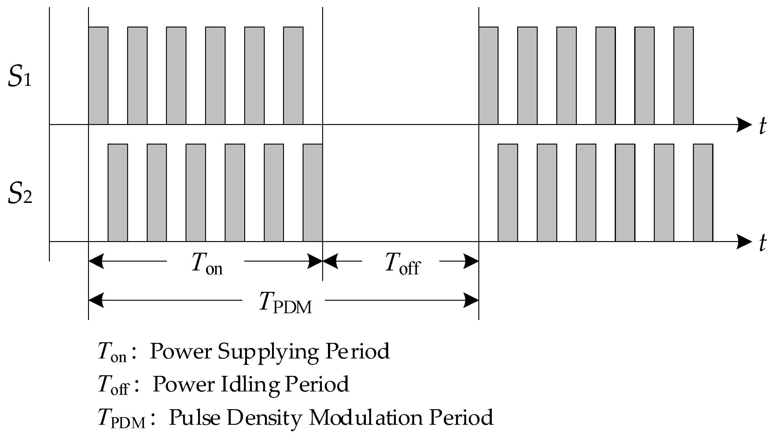
3.2. Principle of Operation

PDM control with gate pulse sequences of the proposed high-frequency inverter is illustrated in Figure 4. Basically, it is operated under either a power-supplying condition or an idling condition. Switching pulse numbers in the period of the PDM determines the output power. DPDM, the PDM duty ratio, is described as follows:
D PDM = T on T on + T off = T on T PDM
The auxiliary snubber inductors LS1 and LS2 allow soft-switching ZCS commutation for the active power switches S1 and S2, which provide the overlapping current mode in S1/DS2 and S2/DS1 when they are in the continuous load current mode. The range of ZCS of the proposed inverter covers all ranges of inverter power regulation. Additionally, the commutation of the ZCS theoretically causes the IGBTs to have zero tail current. Thus, S1 and S2 in the proposed inverter have extremely low switching power losses. Furthermore, power losses are non-existent in this PDM scheme during the non-injected power period compared with the series load resonant inverters employing control methods such as PFM and PWM in light load conditions.

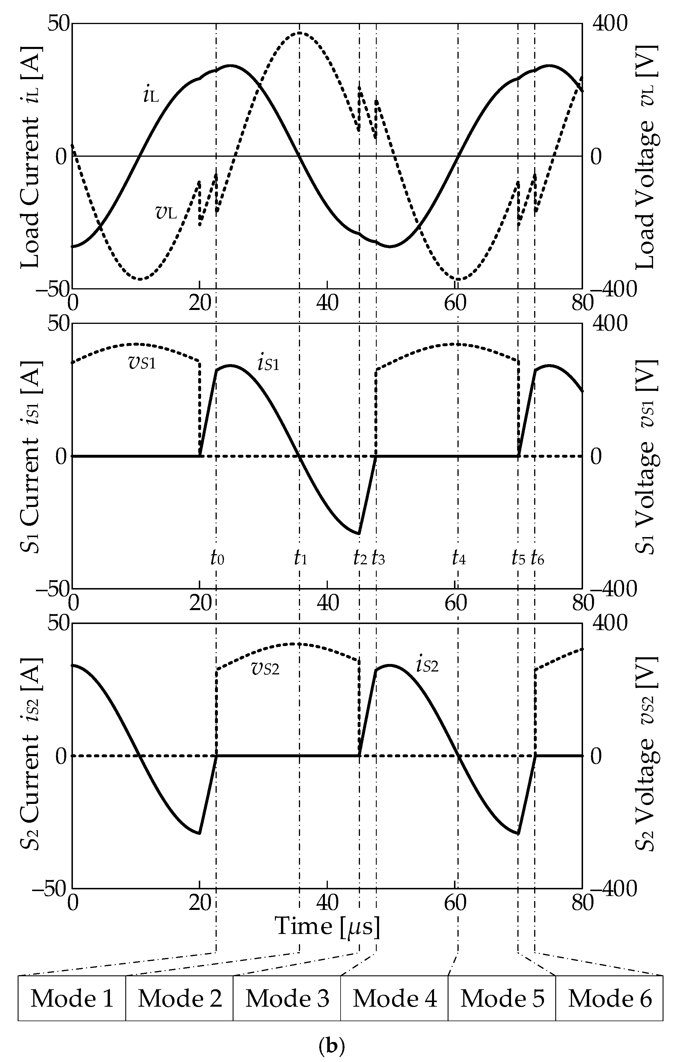
3.3. Operation of the Circuit

The proposed soft-switching inverter circuit mode transitions for the IH fixed roller are shown in Figure 5a. Figure 5b shows the current and voltage waveforms in each mode of operations. Each mode of operating principle is explained as:
Mode 1
With switch S1 in the conduction mode, the power is delivered to the resonant capacitor Cr, snubber inductor LS1 and the IH load. The attenuated sinusoidal resonance starts through the IH load.
Mode 2
When load current iL decreases through S1 to zero at t = t1, anti-parallel diode DS1 is naturally turned on. At turn-off transition, this results in S1 achieving complete ZCS-and-ZVS hybrid soft commutation.
Mode 3
While diode DS1 is in conducting mode, the S2 switch turns on at t = t2. Consequently, the DS1 current commutates to S2. Eventually, the DS1 current is completely transferred to switch S2 by snubber inductor LS2. Therefore, switch S2 achieves ZCS turn-on.
Mode 4
While switch S2 is still in conduction mode, the diode DS1 current becomes zero at t = t3. Then, Cr delivers the output power to the IH load. This results in the attenuated sinusoidal resonance starting through the IH load.
Mode 5
As the load current iL increases, the S2 current decreases to zero at t = t4. As a result, anti-parallel diode DS2 is naturally turned on and S2 turns off by complete ZVS and ZCS throughout this operating mode.
Mode 6
While diode DS2 is still in conduction mode, switch S1 turns on at t = t5. The DS2 current begins to commutate to switch S1. Eventually, the DS2 current is completely transferred to switch S1 due to snubber inductor LS1. As the result, switch S1 is turned on with the ZCS condition, and the circuit operation Modes 1–6 repeat.

4. Experimental Results and Performance Evaluations

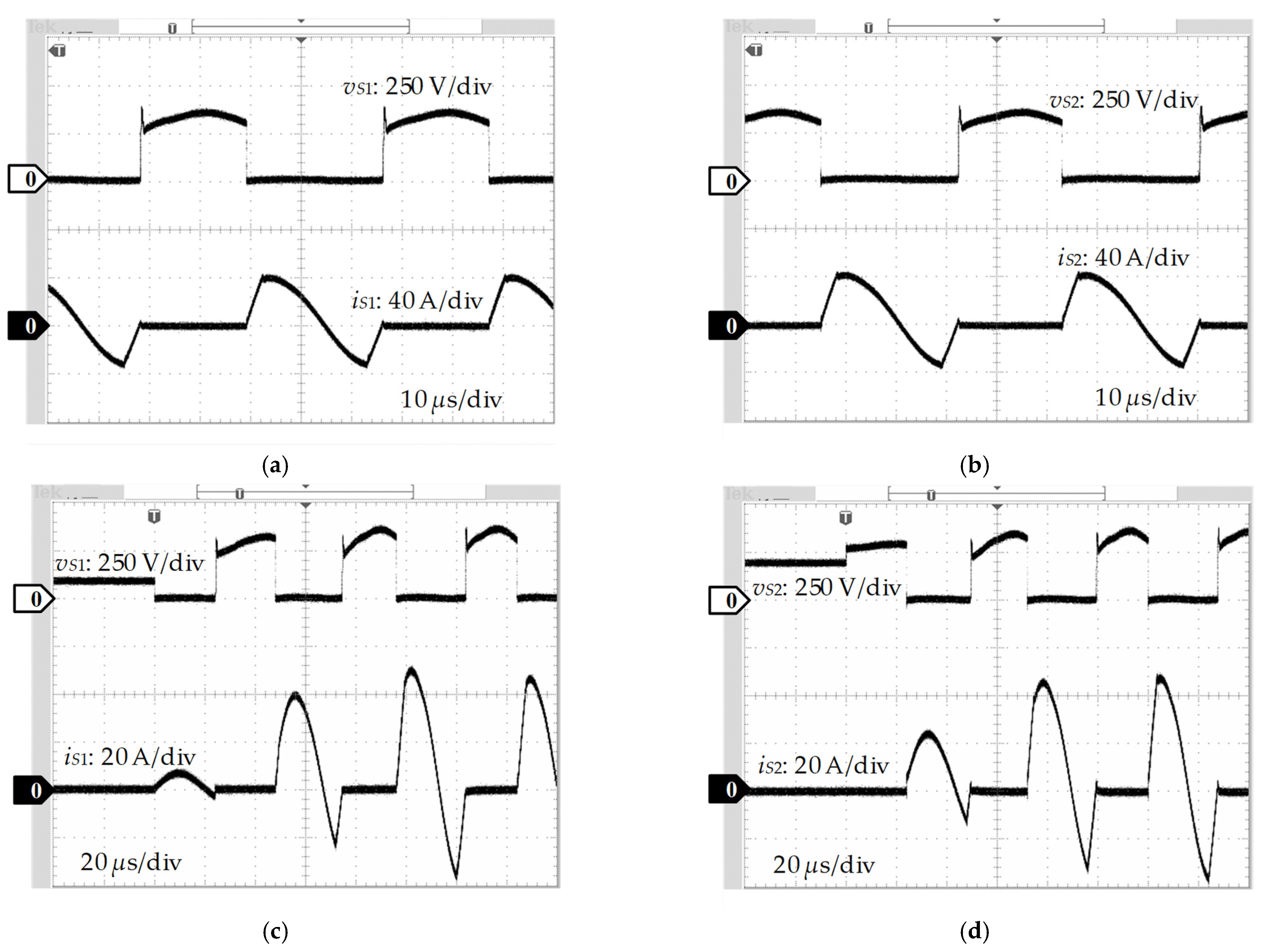
4.1. Voltage and Current Waveforms

The parameters and specifications of the circuit design for the high-frequency PDM-controlled soft-switching series load resonant inverter are listed in Table 1. Inductors LS1 and LS2 are set to 12 µH, as determined by the IGBT’s peak voltage of 350 V. For this circuit, the di/dtmax stress is 12.5 A/µs dynamic switch current and 3.8 µs current overlapping time. Figure 6 shows the IH fixed roller and installed heating coil self-inductance L1. The heating coil, shown in Figure 6b, has a diameter of 50 mm and a width of 350 mm.
The operating waveforms of voltage vL and load current iL for PDM duty ratios DPDM = 0.8 and 0.2 are given in Figure 7. They show that the proposed high-frequency inverter can operate with PDM control.
Figure 8a,b illustrate the operating waveforms of the current and voltage of the power semiconductor switches S1 and S2. These figures show that ZCS soft-switching commutation is achieved in the transitions from turn-on and turn-off. The waveforms of the current and voltage of switches S1 and S2 are shown in Figure 8c,d for the beginning interval of the injection of power. Observing waveforms in Figure 8c,d, the switches S1 and S2 also operate for PDM control implementation using complete ZCS soft-switching commutation.

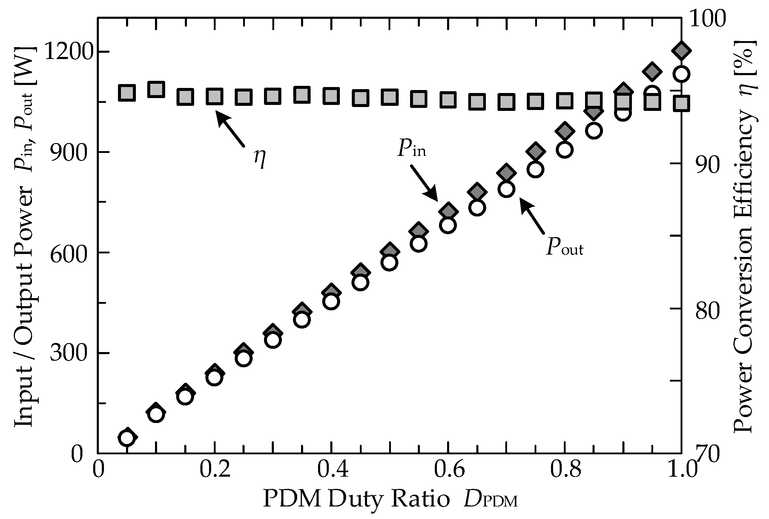
4.2. Power Conversion Efficiencies

The power conversion efficiencies and input/output for the soft-switching high-frequency inverter are given in Figure 9. Changing the PDM duty ratio DPDM causes linear regulation of the output. The PDM operates at DPDM = 1.0 in the printing mode and at DPDM = 0.05 in the stand-by mode. More than 94% power conversion efficiency η can be achieved with a DPDM = 0.05 to 1.0. Thus, the proposed IH fixed roller application in printing and copy machines can achieve high efficiency using the proposed high-frequency inverter system.

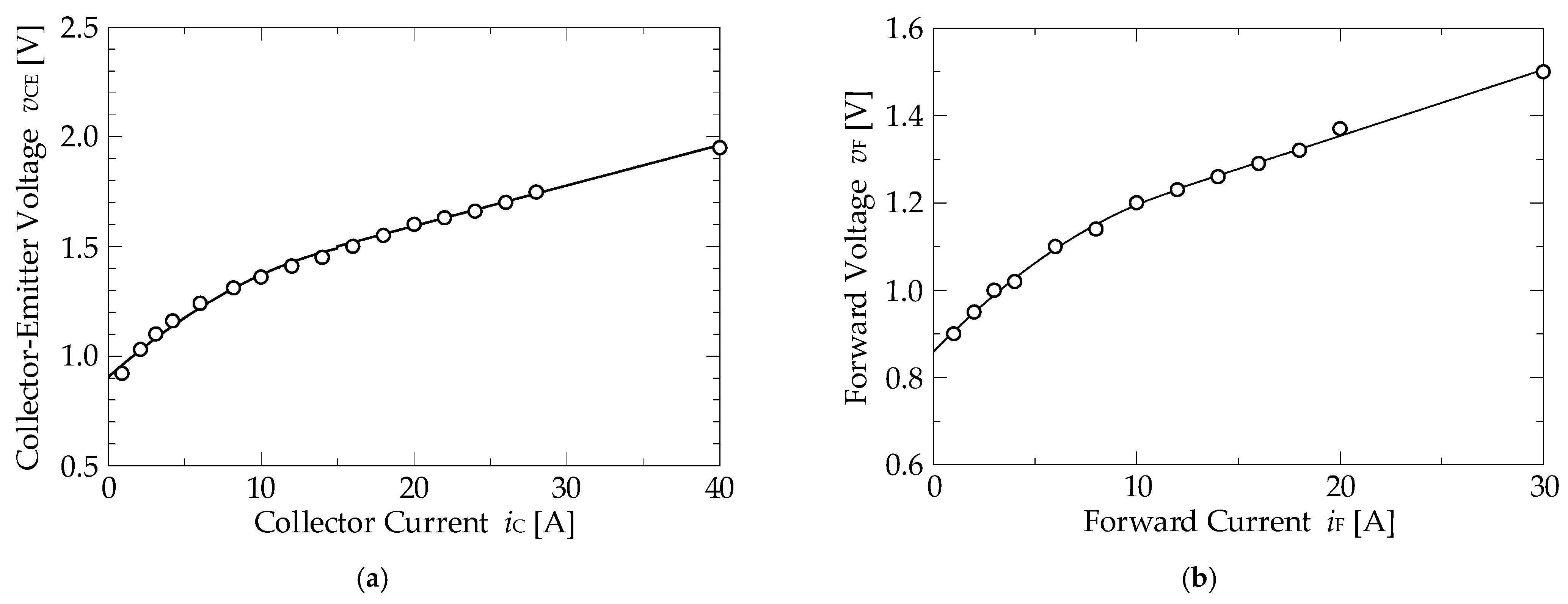
4.3. Analysis of Power Loss

The high-frequency soft-switching power losses of the proposed inverter are extremely low. IGBT fall current and tail current losses are almost zero due to ZCS commutation. Additionally, L1 and snubber inductors LS1 and LS2 conduction losses are negligible due to litz wire usage. The IGBT conduction losses of the proposed high-frequency inverter are the main power losses. The IGBT voltage and current characteristics curves are used for conduction power losses calculations. Figure 10 shows the current and voltage characteristics of the IGBT and that its antiparallel diode has constant temperature conditions. Experimental results yielded the switching characteristics curves. Equations (13) and (14) represent the characteristic curves, which approximate quadratic polynomials in the low forward current area and linear functions in the high forward current area.
v C E = 0.0015 i C 2 + 0.0616 i C + 0.904 ( i C < 15 A ) v C E = 0.0185 i C + 1.223 ( i C 15 A )
v F = 0.00141 i F 2 + 0.0477 i F + 0.859 ( i F < 12 A ) v F = 0.0152 i F + 1.05 ( i F 12 A )
The conduction power loss calculations of the semiconductor are introduced into the simulation algorithm by these equations. Using the above equations in a circuit simulation, the conduction power losses of the diodes and IGBTs can be calculated. Additionally, using Equation (15) and the experimental results, other stray power losses of the reverse recovery losses of the diodes and switching power losses of the IGBT can be estimated separately from the inverter total power losses [29,30]. The power losses analysis results are given in Figure 11.
(Total power losses) − (Conduction power loss) = (Other stray power loss)
In this result, it is obvious that the DPDM ratio of this PDM control scheme increases proportionately with the power losses increase. When the printing mode DPDM ratio reaches 1.0 (heaviest load), only 20% of the total power losses are stray power losses and 80% are conduction power losses. This results from the ZCS soft commutation display low power losses, as seen in Figure 11.

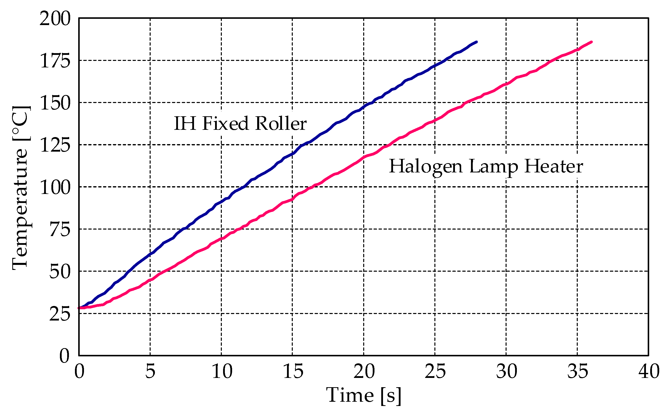
4.4. Halogen Lamp Heater Comparative Characteristics

A comparison of the temperature rise characteristics of the halogen lamp and IH fixed roller heater is given in Figure 12. The graph clearly shows that the IH fixed roller temperature rise is significantly faster than that of the halogen lamp heater.
At an output power of 1200 W, the rise time to reach 185 °C is shown in Table 2. The table compares the rise time and the power consumption of a halogen lamp and an IH fixed roller heater. The Table 2 shows the lower rise time of 27.9 s for the IH fixed roller, while it is 36.1 s for the halogen lamp heater. Additionally, the IH fixed roller uses only 52 Wh, whereas the halogen lamp heater uses 57 Wh in the 100 °C idling mode. Therefore, there is a 9% improvement in the energy consumption.

5. Conclusions

This paper has presented an IH fixed roller high-frequency PDM-controlled series load resonant soft-switching inverter application which is used in printing and copy machines. The operation of the steady-state PDM-controlled inverter’s experimental results are analyzed and evaluated. The proposed high-frequency resonant inverter is operated under the principle of zero-current soft switching across a wide power regulation range by using the PDM control scheme. When the printer uses the output power at very light load conditions such as the stand-by mode, the PDM duty ratio DPDM is at a very small value, which is 0.05 in this experiment. This small output power requires only two or three cycles of injected current from the voltage power source. Therefore, the asymmetrical pattern of PDM pulses is employed so that the injected current becomes easily observable and the control circuit has enough time to get the heat response from the IH system. Then, the ZCS operations are verified at very light load conditions. The power conversion efficiency for power output ranges from 50 to 1200 W is achieved at η > 94%. Power loss calculations are verified through experimental iv characteristics of the diode and IGBT. At heavy load conditions, the stray load power losses amount to be only 20% of the total power losses. This is due to the soft commutation of the ZCS, which yields very low switching power losses. At light load conditions, although the power conversion becomes less effective, the ZCS operations are still achieved. Additionally, the power losses saved by the operations are significant due to the fact that most of the printer operation time is in the stand-by mode. Importantly, the experimental results demonstrate good performance of the proposed high-frequency resonant inverter by replacing the conventional halogen lamp heater with the IH fixed roller. Therefore, the PDM-controlled series load resonant soft-switching high-frequency inverter is proved to be effective for IH applications. Future evaluations of this proposed high-frequency inverter are planned using new wide-bandgap semiconductors, such as GaN FET.

Author Contributions

K.O.: conceived and designed the circuit topology and its control strategy. S.C.: analyzed the circuit topology, verified its control strategy by computer simulations and wrote the manuscript. M.L.K.: revised experiment data, advised for improvements and edited the manuscript. S.S.: prepared circuit prototype and conducted experiments. S.M.: advised for improvements and edited the manuscript. All authors have read and agreed to the published version of the manuscript.

Funding

This research received no external funding.

Conflicts of Interest

The authors declare no conflict of interest.

References

  1. Lucia, O.; Maussion, P.; Dede, E.J.; Burdio, J.M. Induction heating technology and its applications: Past developments, current technology, and future challenges. IEEE Trans. Ind. Electron. 2014, 61, 2509–2520. [Google Scholar] [CrossRef] [Green Version]
  2. Parida, N.; Kumari, V.; Bhaskar, D.V.; Maity, T. Power control techniques used in high frequency induction heating applications. In Proceedings of the International Conference on Circuit, Power and Computing Technologies (ICCPCT), Nagercoil, India, 19–20 March 2015; pp. 1–6. [Google Scholar]
  3. Llorente, S.; Monterde, F.; Burdio, J.M.; Acero, J. A comparative study of resonant inverter topologies used in induction cookers. In Proceedings of the Annual IEEE Applied Power Electronics Conference and Exposition (APEC), Dallas, TX, USA, 10–14 March 2002; pp. 1168–1174. [Google Scholar]
  4. Sarnago, H.; Lucia, O.; Mediano, A.; Burdio, J.M. A comparative evaluation of high-efficiency resonant converters for domestic induction heating. In Proceedings of the Annual Conference of the IEEE Industrial Electronics Society (IECON), Vienna, Austria, 10–14 November 2013; pp. 5016–5022. [Google Scholar]
  5. Zeroug, H.; Meziane, B. Open-loop control of full-bridge resonant inverter for induction metal surface heating. In Proceedings of the Annual Conference of the IEEE Industrial Electronics Society (IECON), Dallas, TX, USA, 29 October–1 November 2014; pp. 3258–3264. [Google Scholar]
  6. Hu, J.; Bi, C.; Jia, K.; Xiang, Y. Power control of asymmetrical frequency modulation in a full-bridge series resonant inverter. IEEE Trans. Power Electron. 2015, 30, 7051–7059. [Google Scholar] [CrossRef]
  7. Millan, I.; Puyal, D.; Burdio, J.M.; Bemal, C.; Acero, J. Improved performance of half-bridge series resonant inverter for induction heating with discontinuous mode control. In Proceedings of the Annual IEEE Applied Power Electronics Conference and Exposition (APEC), Anaheim, CA, USA, 25 February–1 March 2007; pp. 1293–1298. [Google Scholar]
  8. Mishima, T.; Takami, C.; Nakaoka, M. A new current phasor-controlled ZVS twin half-bridge high-frequency resonant inverter for induction heating. IEEE Trans. Ind. Electron. 2014, 61, 2531–2545. [Google Scholar] [CrossRef] [Green Version]
  9. Domínguez, A.; Barragán, L.A.; Otín, A.; Artigas, J.I.; Urriza, I.; Navarro, D. Small-signal model of dual half-bridge series resonant inverter sharing resonant capacitor for domestic induction heating. In Proceedings of the Annual Conference of the IEEE Industrial Electronics Society (IECON), Dallas, TX, USA, 29 October–1 November 2014; pp. 3277–3282. [Google Scholar]
  10. Carretero, C.; Lucia, O.; Acero, J.; Burdio, J.M. Phase-shift modulation in double half-bridge inverter with common resonant capacitor for induction heating appliances. IET Power Electron. 2015, 8, 1128–1136. [Google Scholar] [CrossRef]
  11. Kaewoonruan, S.; Nurach, S.; Lenwari, W. Three level single phase half bridge NPCVSI induction heating with combined phase shift PWM and PFM digital power control. In Proceedings of the International Conference on Electrical Machines and Systems (ICEMS), Pattaya, Thailand, 25–28 October 2015; pp. 569–573. [Google Scholar]
  12. Yeon, J.-E.; Cho, K.-M.; Kim, H.-J. A 3.6kW single-ended resonant inverter for induction heating applications. In Proceedings of the European Conference on Power Electronics and Applications (EPE’15 ECCE-Europe), Geneva, Switzerland, 8–10 September 2015; pp. 1–7. [Google Scholar]
  13. Park, N.-J.; Lee, D.-Y.; Hyun, D.-S. Study on the new control scheme of class-E inverter for IH-jar application with clamped voltage characteristics using pulse frequency modulation. IET Electr. Power Appl. 2007, 1, 433–438. [Google Scholar] [CrossRef]
  14. Ogiwara, H.; Nakaoka, M. ZCS high frequency inverter using SIT for induction heating applications. IEE Electr. Power Appl. 2003, 150, 185–192. [Google Scholar] [CrossRef]
  15. Sugimura, H.; Tanimatsu, H.; Muraoka, H.; Nakaoka, M.; Lee, H.-W. Lossless inductive snubber-assisted soft switching PFM series resonant high frequency inverter for electromagnetic induction eddy current-heated fixing roller. In Proceedings of the International Power Electronics and Motion Control Conference (IPEMC), Xi’an, China, 14–16 August 2004; pp. 138–143. [Google Scholar]
  16. Kifune, H.; Hatanaka, Y. A method of power regulation applied to the high frequency inverter for the IH home appliances. In Proceedings of the European Conference on Power Electronics and Applications (EPE’07), Aalborg, Denmark, 5–9 September 2007; pp. 1–7. [Google Scholar]
  17. Saha, B.; Sugimura, H.; Mishima, T.; Sumiyoshi, S.; Omori, H.; Mun, S.P.; Nakaoka, M. Dual PWM controlled soft switching high frequency IH load resonant inverter with lossless snubbing capacitor and switched capacitor. In Proceedings of the International Conference on Electrical Machines and Systems (ICEMS), Tokyo, Japan, 15–18 November 2009; pp. 1–6. [Google Scholar]
  18. Sugimura, H.; Eid, A.M.; Lee, H.-W.; Nakaoka, M. A voltage-fed series load resonant high frequency inverter with ZCS-PDM scheme for induction-heated fusing roller and extended circuit topologies. In Proceedings of the IEE International Conference on Power Electronics, Machines and Drives (PEMD), Dublin, Ireland, 4–6 April 2006; pp. 146–151. [Google Scholar]
  19. Yonemori, H.; Kobayashi, M.; Suzuki, K. Temperature control of a double-coil drive type IH cooker by means of the PDM control provided with audio noise suppression. In Proceedings of the IEEE International Conference on Electronics, Circuits and Systems (ICECS), St. Julian’s, Malta, 31 August–3 September 2008; pp. 914–917. [Google Scholar]
  20. Zhu, H.; Wang, C.; Peng, Y.; Li, Y. The study of novel PDM-based Induction heating frequency tracking control. In Proceedings of the International Power Electronics and Motion Control Conference (IPEMC), Harbin, China, 2–5 June 2012; pp. 2893–2897. [Google Scholar]
  21. Esteve, V.; Jordán, J.; Sanchis-Kilders, E.; Dede, E.J.; Maset, E.; Ejea, J.B.; Ferreres, A. Enhanced pulse-density-modulated power control for high-frequency induction heating inverters. IEEE Trans. Ind. Electron. 2015, 62, 6905–6914. [Google Scholar] [CrossRef]
  22. Izaki, K.; Hirota, I.; Yamashita, H.; Omori, H.; Wang, S.P.; Jasni, M.; Nakaoka, M. Soft-switched PWM high-frequency load-resonant inverter for induction heating cooking appliance. In Proceedings of the IEEE International Conference on Power Electronics and Drive Systems (PEDS), Singapore, 26–29 May 1997; pp. 169–173. [Google Scholar]
  23. Hoshi, N.; Matsui, A. Improvement of power conversion efficiency of soft-switching inverter in range of low output power by adjustable dead time control. IEEJ Trans. Ind. Appl. 2011, 131, 679–684. (In Japanese) [Google Scholar] [CrossRef]
  24. Fujita, H.; Akagi, H. Pulse-density-modulated power control of a 4 kW, 450 kHz voltage-source inverter for induction melting applications. IEEE Trans. Ind. Appl. 1996, 32, 279–286. [Google Scholar] [CrossRef] [Green Version]
  25. Saha, B.; Lee, H.W.; Nakaoka, M. Series load resonant soft-switched PWM and PDM high frequency inverter using auxiliary active edge-resonant snubber. In Proceedings of the IEEE International Conference on Industrial Technology, Mumbai, India, 15–17 December 2006; pp. 288–293. [Google Scholar]
  26. Ahmed, N.A. High-frequency soft-switching AC conversion circuit with dual-mode PWM/PDM control strategy for high-power IH applications. IEEE Trans. Ind. Electron. 2011, 58, 1440–1448. [Google Scholar] [CrossRef]
  27. Shen, J.; Ma, H.; Yan, W.; Hui, J.; Wu, L. PDM and PSM hybrid power control of a series-resonant inverter for induction heating applications. In Proceedings of the IEEE Conference on Industrial Electronics and Applications (ICIEA), Singapore, 24–26 May 2006. [Google Scholar]
  28. Acero, J.; Lucía, O.; Carretero, C.; Lope, I.; Díez, C. Efficiency improvement of domestic induction appliances using variable inductor-load distance. In Proceedings of the Annual IEEE Applied Power Electronics Conference and Exposition (APEC), Orlando, FL, USA, 5–9 February 2012; pp. 2153–2158. [Google Scholar]
  29. Gao, Z.; Zhou, Y. Research on switching losses for induction heating power supply with LLC resonant load. In Proceedings of the International Conference on Electronic and Mechanical Engineering and Information Technology (EMEIT), Harbin, China, 12–14 August 2011; pp. 2474–2477. [Google Scholar]
  30. Yang, J.; Che, Y.; Ran, L.; Jiang, H. Evaluation of frequency and temperature dependence of power losses difference in parallel IGBTs. IEEE Access 2020, 8, 104074–104084. [Google Scholar] [CrossRef]
Figure 1. Induction heating fixed roller for copy and printing machines. (a) Sectional view. (b) Internal configuration. (c) Toner fixing process.
Applsci 12 01122 g001
Figure 2. Transformer circuit model for IH fixed roller. (a) Transformer model. (b) Transformer equivalent circuit model. (c) L-R series equivalent circuit model.
Applsci 12 01122 g002
Figure 3. Series load resonant high-frequency soft-switching inverter.
Applsci 12 01122 g003
Figure 4. PDM control gate pulse sequences.
Applsci 12 01122 g004
Figure 5. Operating conditions. (a) Circuit mode transitions. (b) Operating waveforms by simulations.
Applsci 12 01122 g005aApplsci 12 01122 g005b
Figure 6. IH fixed roller and heating coil. (a) Fixed roller. (b) Heating coil.
Applsci 12 01122 g006
Figure 7. Load current iL and voltage vL waveforms under PDM. (a) Duty ratio DPDM = 0.2. (b) Duty ratio DPDM = 0.8.
Applsci 12 01122 g007
Figure 8. Current and voltage waveforms for switches S1 and S2. (a) Steady-state condition for switch S1. (b) Steady-state condition for switch S2. (c) Beginning of power injection for switch S1. (d) Beginning of power injection for switch S2.
Applsci 12 01122 g008
Figure 9. Power conversion efficiency and input/output characteristics.
Applsci 12 01122 g009
Figure 10. Current and voltage characteristics of IGBT and diode. (a) IGBT for S1 and S2. (b) Diode for DS1 and DS2.
Applsci 12 01122 g010
Figure 11. Proposed high-frequency inverter power losses analysis.
Applsci 12 01122 g011
Figure 12. Temperature rise characteristics.
Applsci 12 01122 g012
Table 1. Circuit design specifications.
ItemSymbolValue
DC input voltageVin280 V
Resonant capacitorCr0.49 µF
Frequency of switchingf20 kHz
Frequency of PDMf PDM400 Hz
Snubber inductorLS1, LS212 μH
Heating coil self-inductanceL190 μH
IH load time constantτ9.23 μs
Electromagnetic coefficient of couplingk0.48
IGBT (Mitsubishi: CT75AM-12)IC75 A
VCE600 V
Table 2. Characteristics.
ItemIH Fixed RollerHalogen Lamp Heater
Rise time to 185 °C27.9 s36.1 s
Idling mode power consumption52 Wh57 Wh
Publisher’s Note: MDPI stays neutral with regard to jurisdictional claims in published maps and institutional affiliations.

