Article

Study on the Correspondence of Vortex Structures and Vortex-Induced Pressures for a Streamlined Box Girder

1
School of Civil Engineering, Sichuan Agricultural University, Dujiangyan 611830, China
2
Institute of Science and Technology, China Railway Eryuan Engineering Group Co., Ltd., Chengdu 610031, China
3
Department of Bridge Engineering, Southwest Jiaotong University, Chengdu 610031, China
*
Author to whom correspondence should be addressed.
Appl. Sci. 2022, 12(3), 1075; https://doi.org/10.3390/app12031075
Submission received: 29 November 2021 / Revised: 11 January 2022 / Accepted: 18 January 2022 / Published: 20 January 2022

Abstract

:
The main goal of this paper is to explore the mechanism of vortex-induced vibration (VIV) of a streamlined box girder from the perspective of flow field and pressure distribution. In this paper, using the computational fluid dynamic method, the VIV performance of fluid under specific working conditions is simulated and analyzed, especially the distribution and evolution laws of vortex structures in the whole process of VIV are studied in depth. Based on the analysis of the flow field distribution, the corresponding relationship between vortex structures and vortex-induced pressures (VIPs) is discussed. The results demonstrate that the primary cause of VIV for streamlined box girders at large attack angles is the circulation process of the massive vortex structures production and dissipation on the upper surface, rather than the alternate shedding of symmetrical vortex pairs. When vortex structures remain stable, negative VIPs rise in absolute value, negative VIPs occur when vortex structures move backward, and positive VIPs increase when vortex structures fall off.

1. Introduction

Most of the existing VIV-related research focuses on the structural responses, only a small part of them explain the meso-mechanism of VIV. Among them, some of the research objects are regular cross-section structures such as circular cylinders and square columns. Matsumoto et al. (2001) [1] discussed the mechanisms of VIV of inclined cables at a high reduced wind velocity region based on wind tunnel tests, and they found that the axial flow and the upper water rivulet had a controlling impact on the aerodynamic instability of inclined cables. Zhou et al. (2011) [2] proposed helical strake to suppress the VIV of cylinders, which is an effective measure leading to vortex dislocation and swirling flow rather than Karman-type vortex structures. Tumkur et al. (2017) [3] investigated the effects of an internal nonlinear rotating dissipative element on the VIV of a circular cylinder and discovered that this element can affect the wake state and inhibit VIV. Nguyen et al. (2018) [4] indicated that the leading-edge vortex is the main reason for the VIV of 5:1 rectangular cylinders, and that vortex structures impinged on the trailing edge caused the increase in VIV response. The decrease in the value and spanwise correlation of fluctuating lift, as well as the shift of aerodynamic damping from negative to positive, are two explanations for VIV suppression by helical wires, according to Ishihara and Li (2020) [5]. Tamura (2020) [6] described the phenomenon of VIV for circular cylinders and explained the essential mechanisms of VIV based on the mathematical models. Zhao et al. (2016) [7] investigated the impact of the gap ratio on the cylinders’ response in depth and discovered that for all of the computed gap ratios in the tandem configuration, the maximum amplitude is larger than that of a single cylinder. Zhou et al. (2020) [8] conducted experiments to compare the influence of two-dimensional and three-dimensional analysis on the calculation results of VIV responses of rectangular prisms, and discovered that the three-dimensional result is 1.2 times that of the two-dimensional, and that the three-dimensional modal effect and span-wise correlation are important factors. Over a wide range of decreased velocity, Badhurshah et al. (2021) [9] simulated VIV using linear springs as well as bistable springs with two distinct inter-well separations. Additionally, large oscillation amplitudes were discovered to correspond to lift force lock-in with the inherent frequency of the spring-mass system.
In the other part, the mechanisms of VIV of bridges are mainly analyzed from the perspective of the vortex-induced force mathematical model or vibration suppression measures. Zhu et al. (2013) [10] proposed a mathematical model for box girders, and analyzed the mechanisms from the perspective of energy. Mashnad and Jones (2014) [11] developed an analytical model for VIV prediction of long-span bridges, and analyzed the important characteristics of locked-in phenomenon in detail, based on this model. Taking the Hong Kong-Zhuhai-Macao Bridge as the research object, Zhou et al. (2015) [12] discovered that continuous vortex-shedding near the crash barrier is the cause of the vertical VIV of this bridge, and that measuring the flow velocity near the crash barrier can suppress the vertical VIV of this bridge. He and Li (2015) [13] proposed three effective VIV suppression measures and investigated the effects of different parameters of suppression measures on VIV performances. Xu et al. (2018) [14] proposed a method to calculate the VIV performances of bridges and validated this method by calculating the VIV responses of a real bridge while considering the effects of spatial coherence and modal shape of vortex-induced forces. Based on particle image velocimetry (PIV) data, Ma et al. (2018) [15] investigated the impact of grid plates on suppressing the VIV of twin-box girders and discussed the suitable range of grid plate settings. Yang et al. (2020) [16] investigated the VIV performance of a box girder with a self-issuing jet flow method at different angles of attack and analyzed the flow field characteristics. Chen et al. (2020) [17] validated the accuracy of numerical simulation method and model, and the distribution and evolution of VIPs and energy were investigated. Then, the mechanism of VIV for a streamlined box girder was studied from the perspective of force and energy. Oh et al. (2018) [18] explored the prediction technology of VIV wind speed for a road rail bridge and discovered that, because a Strouhal number is a natural characteristic of the section, the wind speed can be accurately estimated at any natural frequency when predicting VIV wind speed. Ground effects on vortex-induced vibration of bridge decks were investigated by Mao et al. (2019) [19], who discovered that periodic vortex shedding generates periodic stresses on the structure, resulting in the development of VIVs. Vortex shifting can be accelerated by ground effects, while aerodynamic forces on the deck are lessened. Huang et al. (2019) [20] proposed a method based on random decrement technology for automatically distinguishing VIV response from huge acceleration response. When this technology is used on the Xihoumen Bridge, it is discovered that the amplitude of VIV decreases with increasing turbulence intensity. Yang et al. (2021) [21] investigated a split three-box girder bridge and reported enormous vortices developed behind the upstream box’s safety barrier, behind the maintenance track, and above the downstream highway box, resulting in severe VIV. The influence of embedded rails on the vortex vibration performance of a long-span bridge was investigated by Xin et al. (2021) [22]. According to the findings, the inclined railing may significantly lower flow pulsation velocity in the wake, as well as the span-wise correlation of flow velocity in the wake. Wang and Zhang (2021) [23] investigated the effect of the torsional-bending frequency ratio on the VIV performance of π-shaped sections and discovered that torsional motion causes a small amount of energy to be transferred from vertical to torsional.
The computational fluid dynamics (CFD) approach is gradually maturing due to significant advancements in computer technology. For the fluid-structure coupling dynamic analysis, with the help of CFD simulation, the pressure distribution on the structural surface can be easily obtained [24,25,26,27], and the visualization of flow field can also be realized readily [28,29,30]. Xu et al. (2020) [31] investigated the VIV performance of circular steel hangers utilizing simulation methods and proposed a simplified method to calculate the equivalent static forces of VIV. Mannini et al. (2016) [32] focused on a trapezoidal box girders and investigated the influence of degree of sharpness on the aeroelastic behavior via numerical simulations of the flow field. Hu et al. (2021) [33] focused on the relationship between vortex drift mode and vibration response in the locking range of VIV and established a simplified vortex model for streamlined closed-box girders. Zhang et al. (2020) [34] used a numerical method to investigate the effect of several aerodynamic measurements on the VIV properties of a two-box edge girder and discovered that the strength of vortices around the upper and lower surfaces of the section decrease, effectively suppressing vertical VIV. Noguchi et al. (2020) [35] investigated the VIV performance of a box girder and discovered that when employing a numerical simulation approach, a wide span-wise domain is necessary to compute the VIV amplitude. Fang et al. (2021) [36] used numerical modeling to investigate the source of vertical VIV in a truss girder with two decks and discovered that the vertical VIV of the bridge is likely caused by vortices behind or above the upper deck, which is connected to the guardrails.
Based on the advantages of the CFD technology mentioned above, this paper investigates in depth the VIV mechanisms of a streamlined box girder from the perspective of the combination of flow field and pressure distribution. This paper is organized as follows. Section 2 introduces the simulation method and model utilized in this paper. Then, Section 3 presents the evolution of vortex structures in the whole VIV process of the most significant condition is explored. Section 4 combines the distribution of vortex structures and VIPs, the corresponding relationship between vortex structures and vortex-induced pressures is preliminarily established. Finally, the conclusions are given in Section 5.

2. Method and Model

2.1. Governing Equations

This numerical simulation used the unsteady RANS technique using the commercial program FLUENT. In the Cartesian coordinate system, for the incompressible viscous fluid flow, the governing equations can be written as
u i / x i = 0 ,
ρ u i t + ρ u i u j x i = p x i + μ 2 u i ρ u i u j ¯ x i ,
where ρ and μ are the density and the viscosity coefficient of air, respectively; subscript i, j represent the coordinate axis in space with i = 1, 2 and j = 1, 2 for two-dimensional simulation; xi is the coordinate value along the i axis; u j and u j are the average velocity and the fluctuating velocity along j axis, respectively; t is the time; p is the pressure; ρ u i u j ¯ is the so-called Reynolds stress and was represented by SST k ω turbulence model in this simulation. Using the second-order technique based on the finite volume method, the governing equations were discretized. For pressure-velocity coupling, the SIMPLEC algorithm was applied. In the standard format, the pressure was discretized. The second-order form was used to discretize the momentum, turbulent kinetic energy, and specific dissipation rate. A least-square cell-based technique was used to deal with gradient terms.

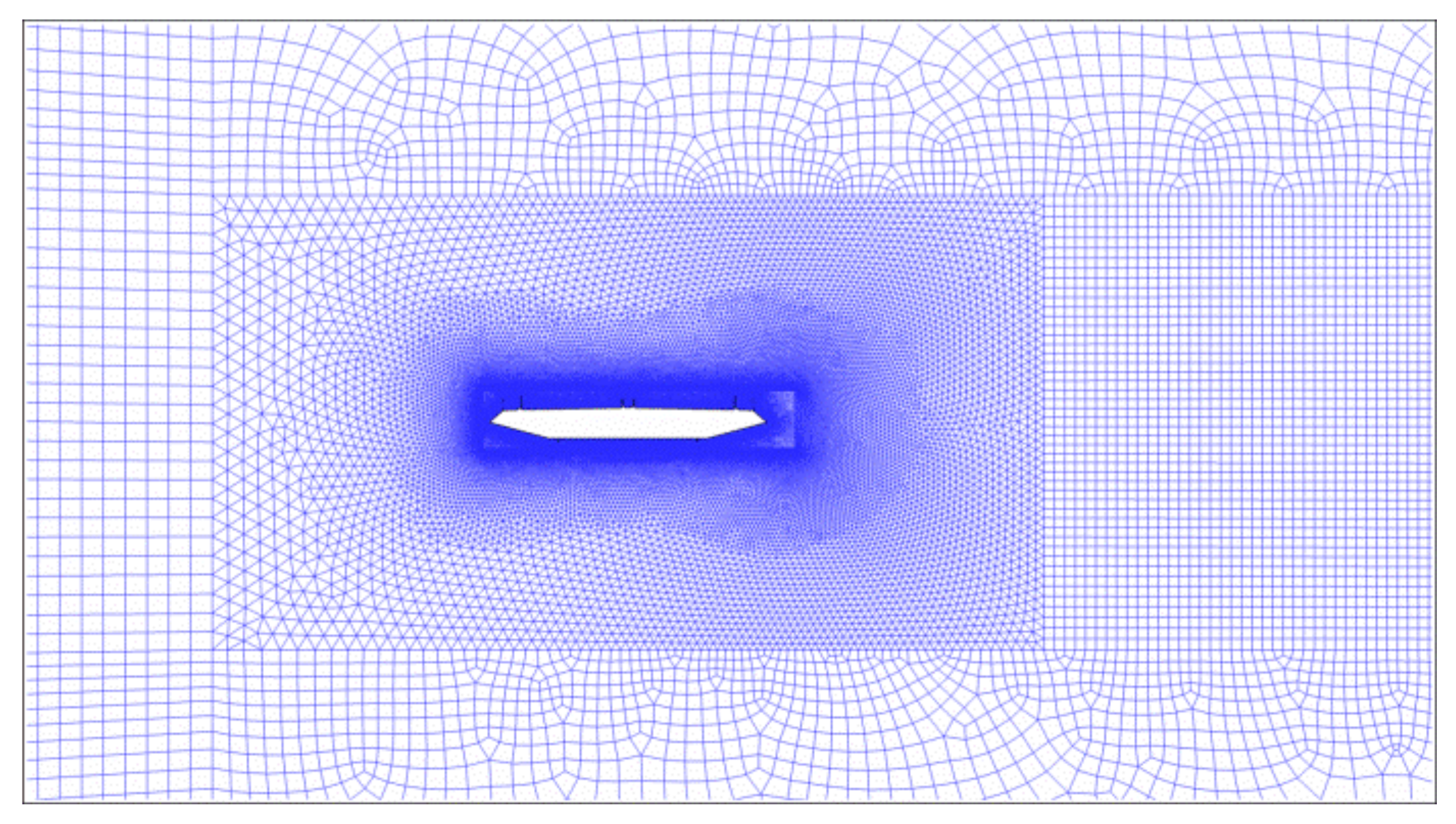
2.2. Simulation Model

Figure 1 shows the domain settings around this girder, and this scaled girder’s structural damping ratio and vertical natural frequency are 0.5% and 2.807 Hz, respectively. The total size of the computational domain is 18B × 28D, where B and D are the width and height of the scaled girder model separately. The scaled model is one-twentieth the size of the original structure, which is 32 m wide and 5.2 m high. The computational domain is divided into four sections: rigid domain, dynamic-mesh domain, wake domain, and outer domain. The rigid domain has a width of 1.12B and a height of 1.25D, and it travels in lockstep with the bridge girder. The rigid domain is filled with a structural mesh with fifteen boundary layers to ensure the accuracy of the simulation results near the girder. The dynamic-mesh domain is 3B × 10D in size and is filled with a dynamic mesh made up of triangular grids. Because there may be a vortex street behind the bridge girder, the grids in wake domain are densified to clearly reflect this phenomenon. The outside domain, distant from the girder, is filled with bigger structured girds in order to increase computing efficiency, as shown in Figure 2.
The wind attack angle is considered as +5° in this simulation. In this case, the left and lower directions of the girder are the sources of the incoming wind, while the right and higher directions represent the wind flow’s outflow. The velocity inlets are defined as the left and lower boundaries, with a uniform wind speed of 9.1 m/s, a turbulent intensity of 0.02, and a turbulent viscosity ratio of 2; the pressure outlets are defined as the right and top boundaries, with a relative pressure of zero; and the no-slip wall boundary is defined as the surface of the streamlined box girder. Moreover, Chen et al. (2018, 2020) [17,27] performed a rigorous independent assessment of the grid and time step of this simulation, and the procedure of VIV numerical simulation by combining structural dynamics equation with fourth-order Runge-Kutta method was also detailed in the references, and the correctness of the numerical simulation results has been validated by comparing with wind tunnel test data.

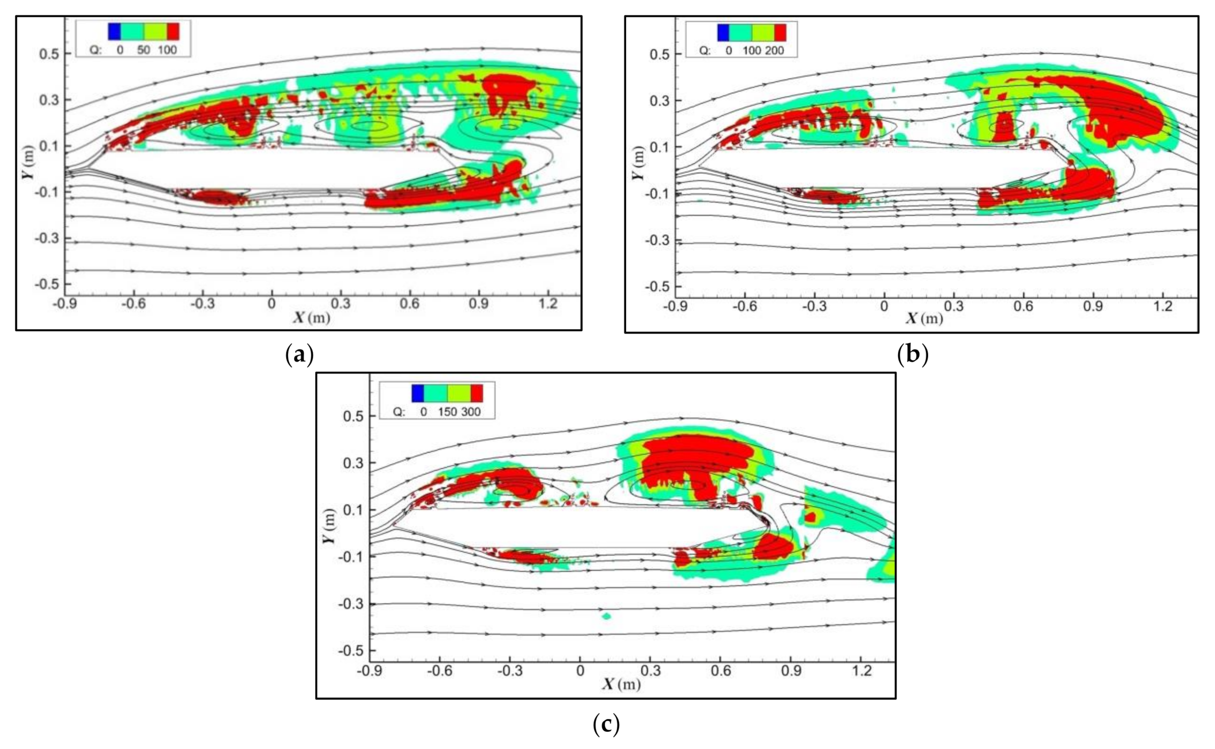
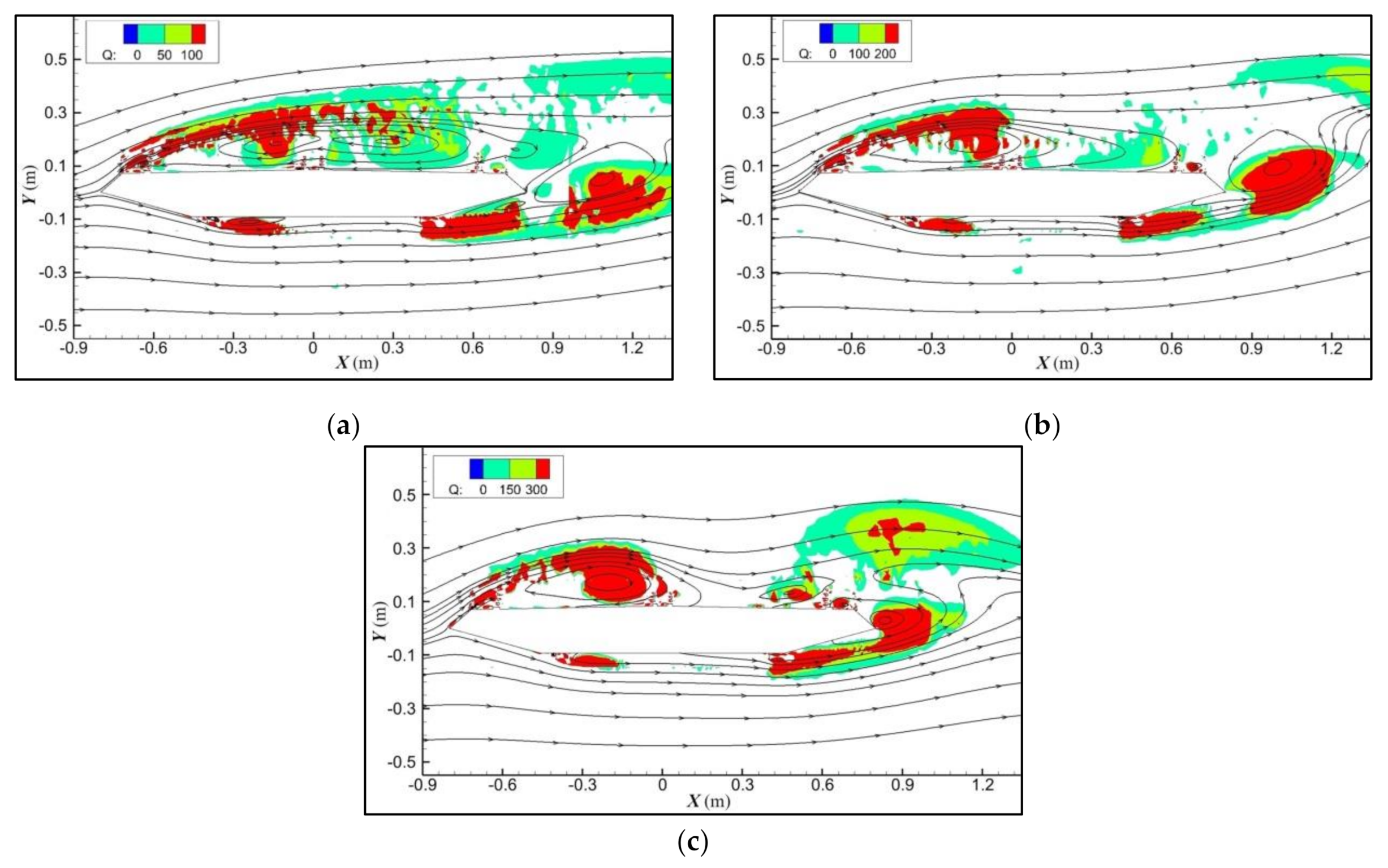
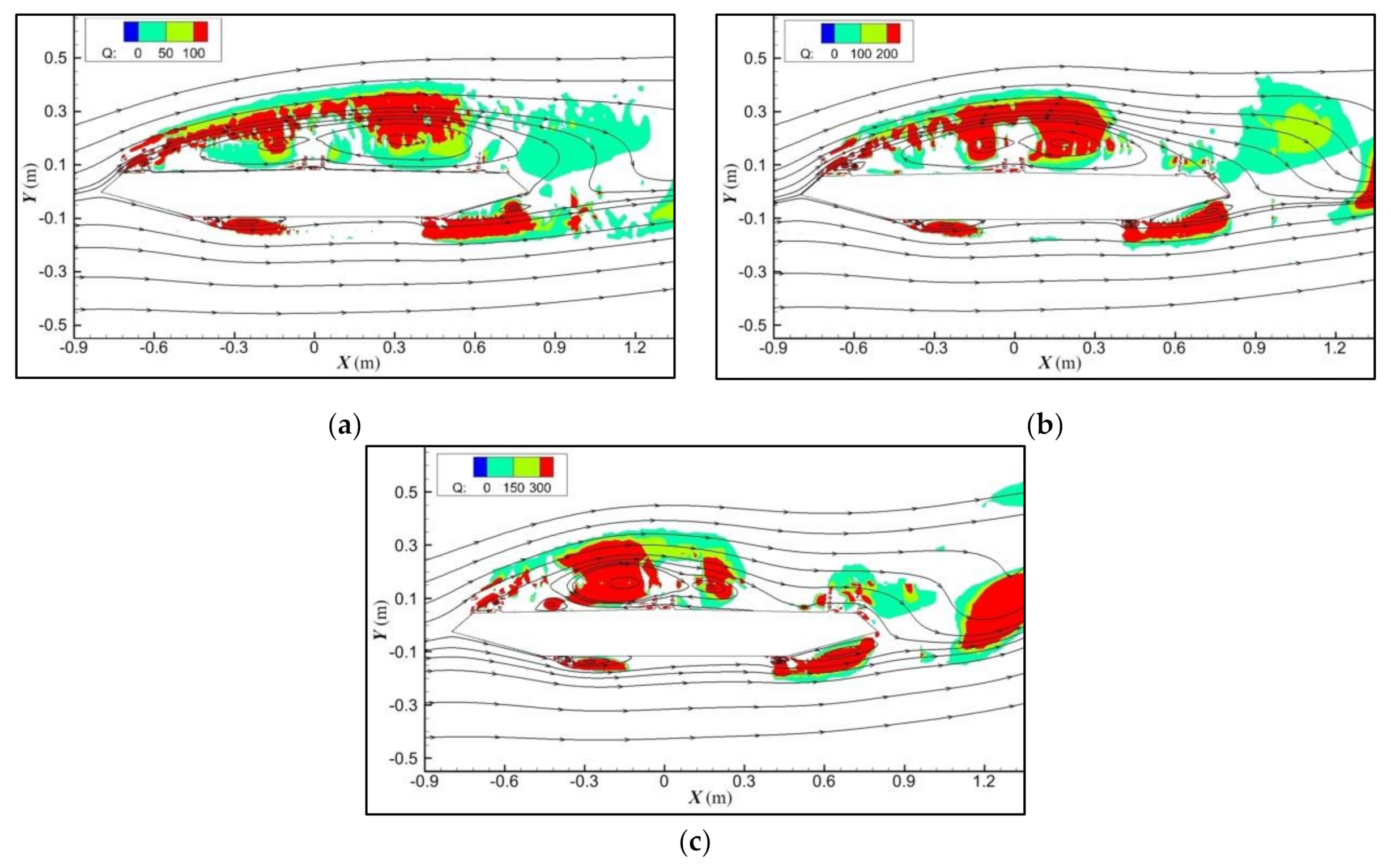
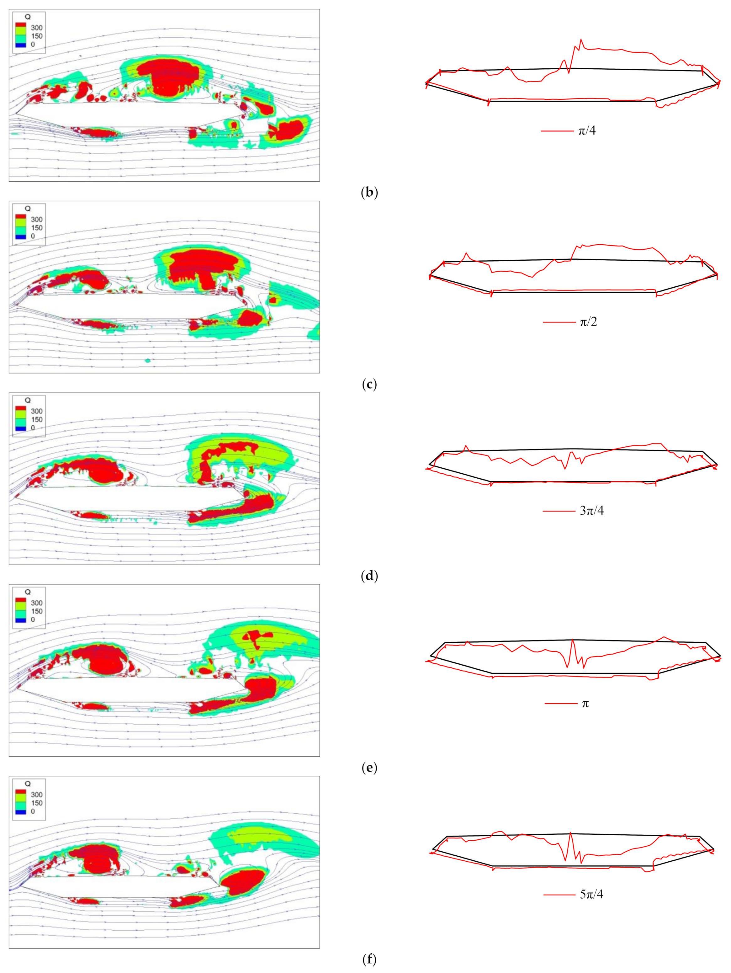
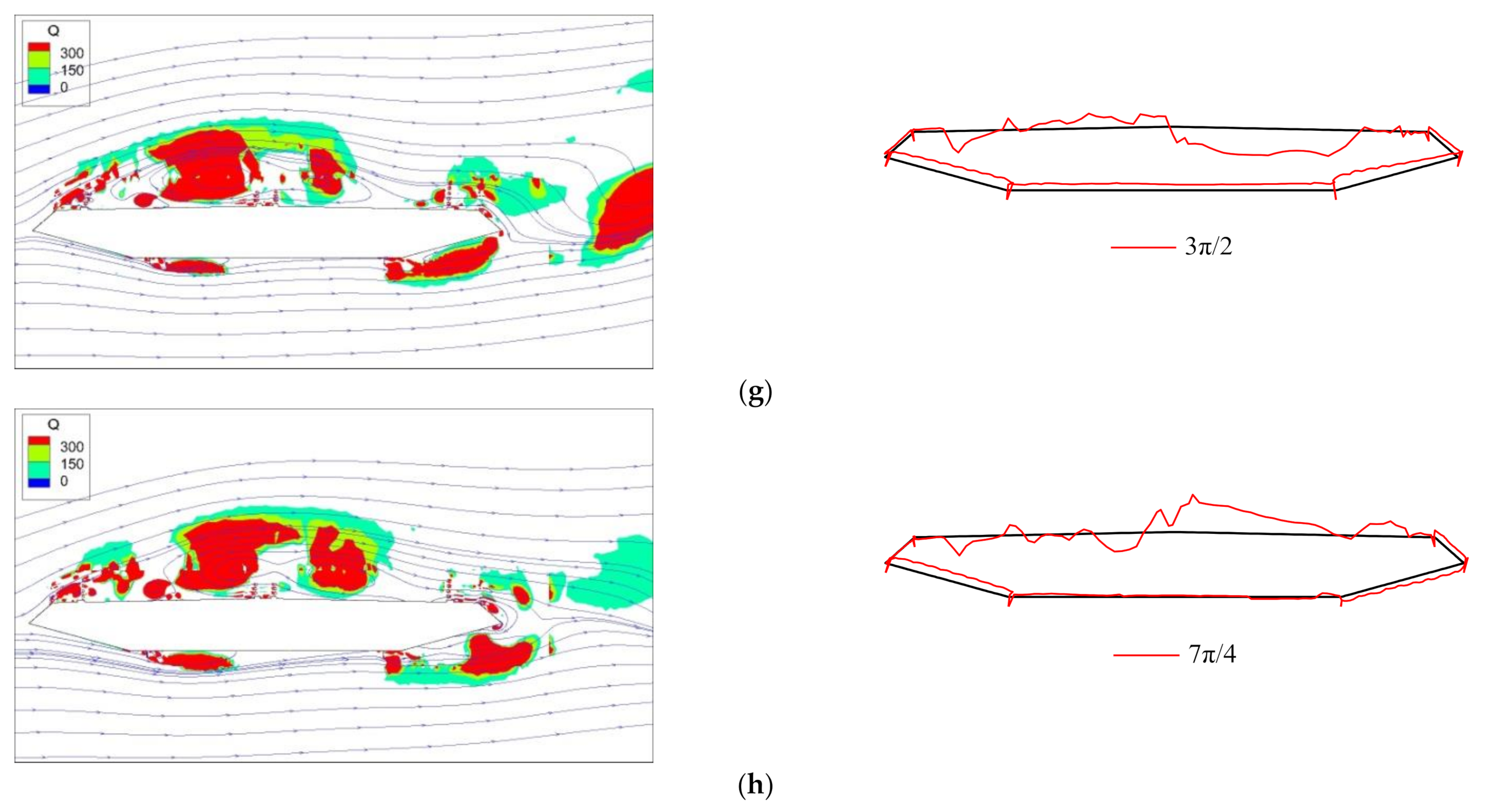
3. Distribution and Evolution of Vortex Structures

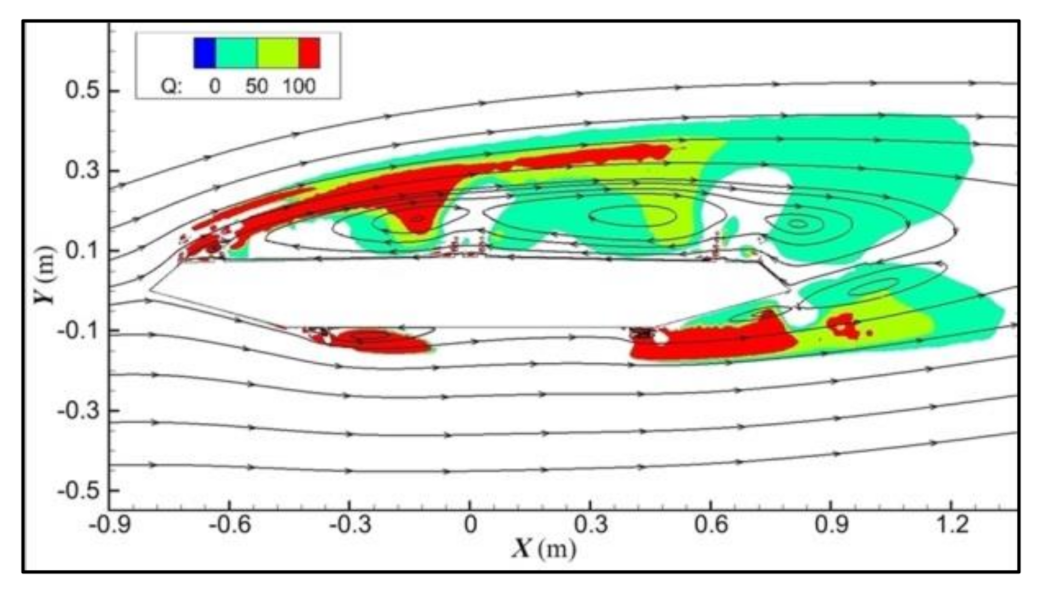
3.1. Determination of Vortex Structures

As is known to all, one of the advantages of numerical simulation is visualization, whilst an important characteristic of VIV is vortex. In this study, this advantage was applied on the vorticity analysis to visualize the vortex structures. According to Chen et al. (2014) [37], the vorticity field ( ω ) is related to the velocity field as
ω = × u ,
where u is the velocity vector (u, v, w) of a flow field; is the vector differential operator.
As this is a two-dimensional incompressible flow in this study, there is only one nonzero component of the vorticity field, it is
ω z = v x u y ,
Based on ω z , the location of vortex structures can be easily identified. However, the vorticity comprises not only the vortex motion of the flow, but also the shearing motion of the flow, particularly near the boundary layer, where the shearing motion plays a prominent role. To eliminate the influence of the shearing motion, Hunt et al. (1988) [38] proposed to use the Q-criterion to replace the vorticity. Dubief and Delcayre (2000) [39] confirmed that Q-isosurfaces turn out to display very nice coherent vortex structures. The Q-criterion is called after the second invariant of the velocity gradient tensor, which is more accurate and suited for describing vortex forms. For two dimensional incompressible flows, the second invariant Q can be written as
Q = u x v y v x u y ,

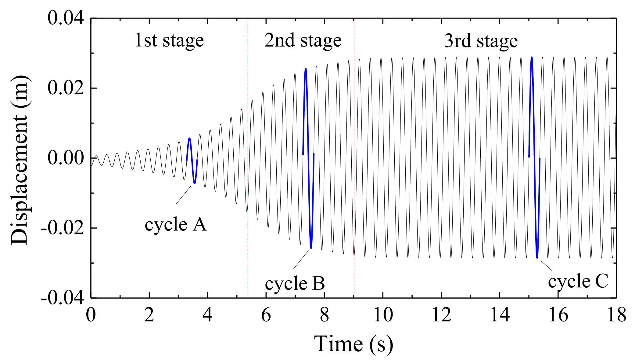
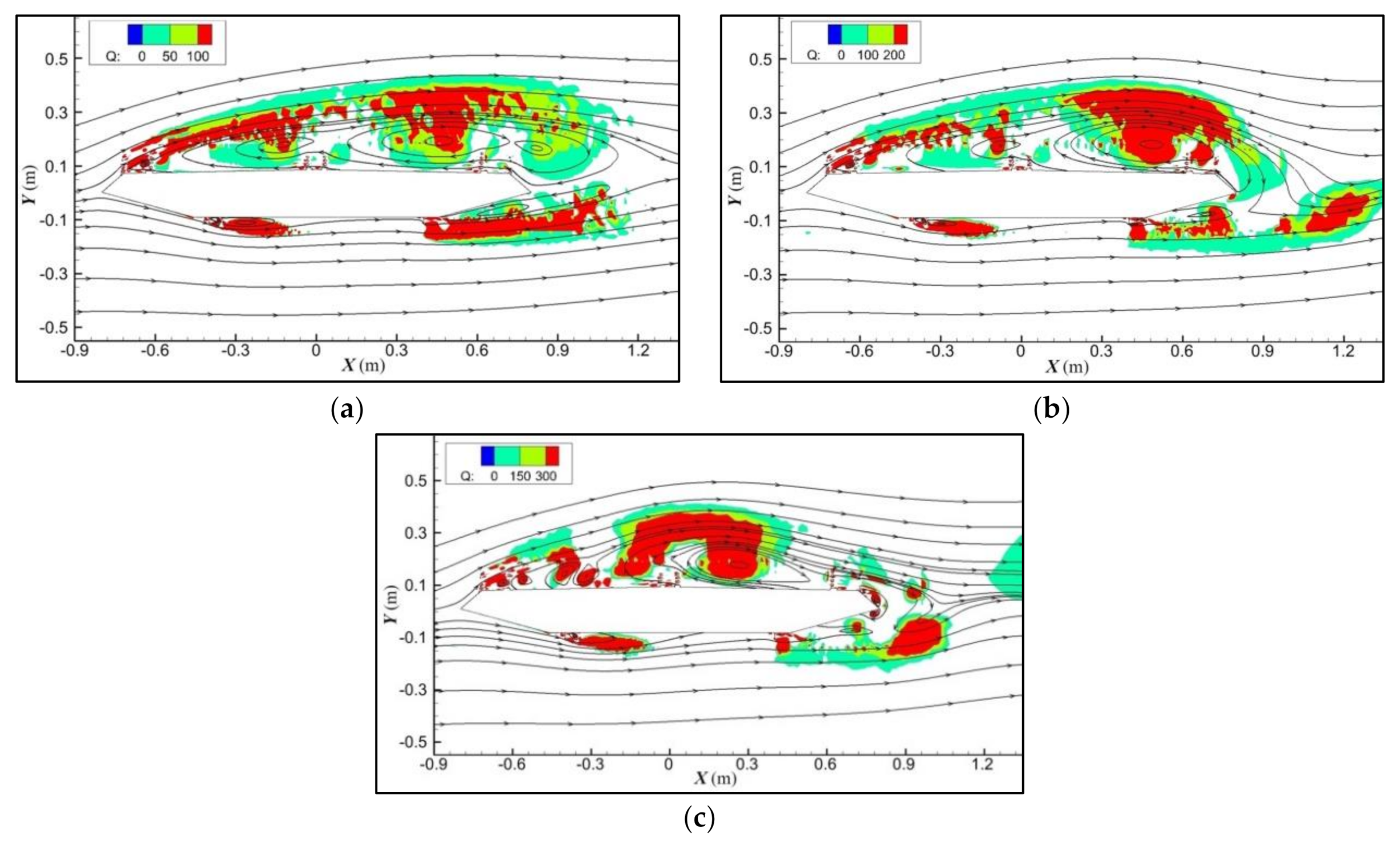
3.2. Evolution of Vortex Structures in the Whole Process of VIV

Figure 3 depicts the displacement response of the box beam’s vertical VIV. The growth process of VIV is split into three stages, namely, rapid development stage, gradual convergence stage, and stable vibration stage, in order to investigate the evolution law of vortex during the development of VIV. Then, four moments of 0, π/2, π, and 3π/2 are selected for the average state of each stage, corresponding to the equilibrium position with upward motion, the positive maximum amplitude, the equilibrium position with downward motion, and the negative maximum amplitude, respectively.
The size and distribution of vortex structures at the above-mentioned four moments in different stages of VIV are shown in Figure 4, Figure 5, Figure 6, Figure 7 and Figure 8.
As shown in Figure 4, when this streamlined box girder remains stationary, a huge vortex locates at the upper surface, and it consists of four sub-vortex structures which locate at the leading edge of the roof, the upstream roof, the downstream roof, and the upside of downstream web separately. As the influence of upstream corner and railings, a very small sub-vortex forms at the leading edge of the roof. The two large sub-vortex structures located at the roof are not linked together because of the central barriers. Additionally, as an effect of the downstream railings and corner, the sub-vortex separates from the main vortex structure. The horizontal dimensions of four sub-vortex structures at the upper surface, from left to right, are 0.04 m, 0.24 m, 0.61 m, and 0.14 m, respectively. Different from the upper surface, the vortex structures of the lower surface are more dispersed. Several small vortex structures form behind the track maintenances. It is noticeable that a large vortex consisted of two sub-vortex structures locates at the underside of the downstream web, and the horizontal dimension of this vortex is 0.57 m.
At 0 moment, the vortex distribution at different stages of VIV is shown in Figure 5. As shown in Figure 5a, the vortex distribution during the rapid development stage is similar to that of the static box girder, because the vertical displacement of the girder is small, and the influence of the small motion on the surrounding flow field is not obvious. As shown in Figure 5b, compared with the rapid development stage, there is still a huge vortex on the upper surface of the box girder, but the number of sub-vortex structures in the vortex is reduced to three with the increase in the VIV amplitude. The sub-vortex on the windward side of the upper surface of the box girder is closer to the central guardrail, and its horizontal dimension is 0.12 m. There is only one sub-vortex on the leeward side with the horizontal dimension of 0.73 m, which may be formed by the fusion of two sub-vortex structures on the leeward side at the rapid development stage. Different from the situation in which the tail sub-vortex will fall off at the first stage, the position of the sub-vortex is closer to the upper inclined web of the leeward side. On the bottom surface of the box girder, there is only one vortex on the leeward inclined web, while for the static girder, this sub-vortex at the back of the position has fallen off. At the stable period, as shown in Figure 5c, there are several separated vortex structures on the upper surface of the box girder, the largest vortex is located at the middle and rear of the upper surface with a horizontal dimension of 0.42 m, and this vortex has not yet completely passed through the central guardrail. The size of the vortex around the leeward inclined web of the box girder is small, and a vortex behind the box girder has fallen off from the lower surface. There is a vortex on the leeward wind fairing that is composed of two sub-vortex structures located on the upper and lower sides of the wind fairing, respectively. Comparing the distribution of vortex structures in three different stages of VIV, it can be found that with the development of VIV, the vortex structures with a larger Q value on the upper surface are closer to the middle of the box girder, and the vortex structures with strip distribution behind the windward railing gradually become independent vortex structures closer to the upper surface of the box girder.
Then, at π/2 moment, the vortex distribution at different stages of VIV is shown in Figure 6. Figure 6a shows that during the first stage of VIV, the vortex structures at the tail of the upper surface grab part of the vortex structures on the leeward side of the upper surface and fall off the surface of the box girder. The horizontal dimensions of three sub-vortex structures on the upper surface are 0.19 m, 0.45 m, and 0.38 m, respectively, and the vortex size on the leeward side of the box girder increases to 0.44 m. The size of the vortex formations on the windward side of the upper surface rises during the gradual convergence stage of VIV, as seen in Figure 6b. The majority of the vortex structures on the leeward side had detached from the surface of the box girder, with only a minor portion remaining on the upper surface’s windward side. On the leeward side of the lower surface, the vortex patterns near the inclined webs increase dramatically. In the stable stage of VIV, the vortex distribution around this girder is obviously different from the first two stages, as shown in Figure 6c.
It can be seen from the figure that during the upward movement of the box girder from the equilibrium position, the size of the vortex on the windward side of the upper surface increases, and another large vortex has bypassed the central guardrail and reaches the leeward side of the upper surface. At this time, no vortex falls off from the upper surface, and the vortex sizes on the upper surface are 0.45 m and 0.51 m, respectively. On the lower surface, a vortex has fallen off from the leeward inclined web, and a new vortex is formed here. Compared with the vortex distribution at different moments, it can be found that the vortex on the upper surface of the box girder moves downstream, while the vortex size on the lower surface increases obviously. Comparing the vortex distribution at three different stages, it can be seen that vortex shedding has occurred in the rapid development stage, is occurring in the gradual convergence stage, and has not occurred in the stable vibration stage. Moreover, on the leeward inclined web of the lower surface of the box girder, the size and vorticity of vortex structures are smaller in the stable vibration stage.
At π moment, the vortex distribution at different stages of VIV is shown in Figure 7. It can be seen from Figure 7a that in the rapid development stage, there is a large vortex with a horizontal dimension of 0.48 m behind the leeward inclined web on the lower surface of the box girder, which is about to fall off from the surface, and this is caused by the downward movement of the box girder to squeeze the airflow below. On the upper surface, a huge vortex is blocked by the central guardrails and separated into two sub-vortex structures. Meanwhile, there is a vortex with small vorticity on the leeward inclined web. The vortex distribution around the box girder in the gradual convergence stage is shown in Figure 7b. In this stage, vortex shedding also occurs on the leeward inclined web of the lower surface, with the size of 0.31 m, and because of the increase in the VIV amplitude of the box girder, the vertical motion of this vortex is more obvious and closer to the inclined web of the upper surface. On the upper surface, some vortex structures on the leeward roof dissipate and some vortex structures are captured by the vortex structures on the windward roof, so the size of the vortex on the windward roof increases to 0.54 m. It can be seen from Figure 7c that during the stable vibration stage, due to the downward movement of the box girder, the vortex attached to the leeward wind fairing moves upward to the top of the wind fairing. The size of the vortex on the windward side of the upper surface continues to increase to 0.47 m. Meanwhile, vortex shedding occurs on the leeward side, and the vortex size on the leeward roof is only 0.18 m. The vortex shedding process on the leeward side of the top surface is virtually complete, and the huge vortex is positioned on the middle and front of the upper surface, while the large vortex on the lower surface will fall off at this time, according to the comparison.
At 3π/2 moment, the vortex distribution at different stages of VIV is shown in Figure 8. The little vortex on the leeward inclined web of the top surface has dropped off, the size of the vortex on the leeward roof increases to 0.65 m, and the size of the vortex on the windward roof decreases to 0.13 m, as shown in Figure 8a. The vortex behind the leeward inclined web of the lower surface has moved far behind the box girder. As shown in Figure 8b, in the gradual convergence stage, the vortex on the upper surface is divided into two parts by the central guardrails, and the size of the two sub-vortex structures is 0.14 m and 0.29 m, respectively. The vortex behind the leeward inclined web on the lower surface has also fallen off. The vortex on the leeward wind fairing has dropped off the surface in the steady vibration stage, and the little vortex on the leeward roof of the top surface flows backward and is spread through the leeward railing, as shown in Figure 8c. Furthermore, the vortex on the top surface’s windward side goes to the leeward side, which is prevented by the central guardrails, with just a small portion of the vortex reaching the leeward roof. It can be concluded that the large vortex structures on the upper surface of the box girder are located on the leeward roof in the first two stages of VIV, while the motion of the vortex structures in the stable vibration stage lag behind, the vortex structures are still on the windward roof.
In conclusion, the scale and distribution of vortex are obviously different in different stages of VIV, and the motion of vortex structures in the stable stage lag behind the other two stages. During the upward movement of the box girder, the vortex shedding occurs at the tail of the upper surface, and the size of vortex structures at the lower surface increase. Vortex shedding happens at the tail of the lower surface during the downward movement of the box girder, and the size of vortex formations at the upper surface increases. In addition, combined with the flow field distribution, it can be found that the incoming flow is blocked by the wind fairing, railings, and other structures, resulting in vortex structures at the leading edge of the box girder. The source of the vortex is the shape parameters of the windward side of the box girder, including the angle of the wind fairing, the height, and spacing of the railings.

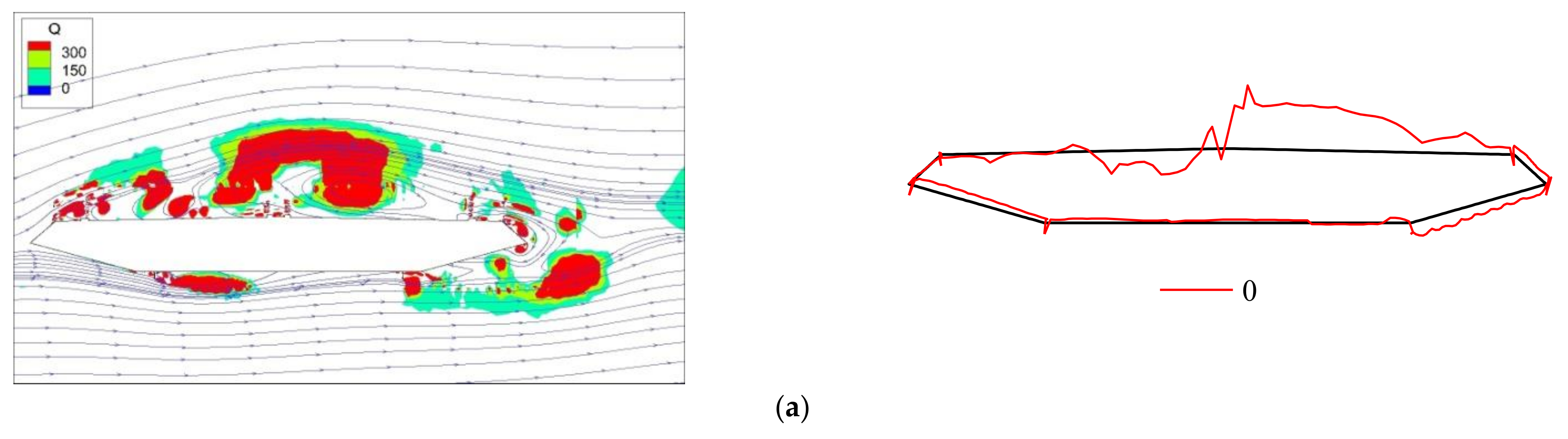
4. Correspondence of Vortex Structures and Vortex-Induced Pressures

4.1. Determination of Vortex-Induced Pressures of Each Point

It is necessary to obtain the characteristics of force on the girder’s surface in order to explain the mechanisms of VIV of the streamlined box girder. In order to extract the time histories of the fluctuating pressures spread on the girder surface from the simulated results, 301 pressure points are placed on the girder at unequal intervals. According to Chen et al. (2020) [17], the VIPs of 301 points can be extracted from the pressures through the following formulas
p ˜ V 0 t i = m 0 i y ¨ 0 ( t ) c 0 i y ˙ 0 t ,
p V I t i = p ˜ V t i + m 0 i y ¨ ( t ) + c 0 i y ˙ t ,
where i , ranges from 1 to 301, and represents the order number of the pressure point; p ˜ V 0 i is the fluctuating pressure at the ith point during a free decay vibration excited by an initial displacement under the zero wind speed; m0i and c0i are the non-wind-induced additional mass and damping coefficient at the ith point; p ˜ V   i and p V I   i are, respectively, the fluctuating pressure and the VIP at the ith point during the VIV at a certain wind speed; obviously, the velocity and acceleration of each point are synchronized at the same time. Meanwhile, it should be ensured that the sum of the VIPs must be equal to the total VIF, which is
i = 0 301 p V I t i = f V I ( t ) ,

4.2. Relation between Vortex Structures and VIPs at the Stable Stage of VIV

The distribution and development of vortex at each step of VIV of the box girder were examined in the preceding section. The VIPs are illustrated by red lines in Figure 9, which illustrates the distribution of vortex and VIPs at eight points in a vibration cycle during the stable stage of VIV.
At 0 moment, several small vortex structures generate on the leading edge of the upper surface and windward roof, and the VIPs are positive at the corresponding areas. There is a huge vortex in the middle and rear part of the upper surface, which tends to move backward, causing negative pressure with a large absolute value. At 5° wind attack angle, the flow field around the lower surface of the box girder is relatively stable, and the vortex-induced pressure on the windward inclined web and bottom plate of the lower surface is positive. There is obvious vortex shedding on the leeward inclined web of the lower surface, which leads to negative pressure with a larger absolute value.
At π/4 moment, compared with the previous moment, the huge vortex on the upper surface continues to move backward, and has passed through the central guardrails to the leeward lane, and the corresponding peak value of VIPs also moves backward. The absolute value of negative pressure on the leeward inclined web of the lower surface decreases because the shedding vortex continues to move away from the region, and the change of vortex and VIPs in other parts is not obvious.
At π/2 moment, the large vortex on the leeward side of the top surface moves backward and tends to break away, and the peak value of the VIPs in this region decreases. Several small vortex structures on the windward side of the top surface have merged to form a larger vortex, and the VIPs in this region are still positive, and the pressure value increases slightly. Although there is a region with obvious vorticity at the right rear of the leeward inclined web on the lower surface, the vorticity field and streamline in this region do not change significantly, so the corresponding VIPs do not change significantly.
The enormous vortex on the windward side of the upper surface remains nearly motionless during the downward movement of the box girder, and the positive pressure in this region progressively declines. The enormous vortex on the leeward side of the top surface dissipates, and the forward flow bypasses the large vortex structures on the windward side of the upper surface, acting directly on the leeward roof, resulting in a large positive pressure. The amount of the residual vortex in the roof’s back end is modest, resulting in a considerable amplitude of positive pressure in this area. The positive VIPs in this location are caused by vortex structures on the top surface’s leeward inclined web. On the lower surface’s leeward inclined web, new vortex structures appear, and the accompanying VIPs change from negative to positive.
At 3π/2 moment, the large vortex on the upper surface moves backward, but the main structure of this vortex is still located on the windward roof due to the obstruction of the central guardrail, and the VIPs of the windward roof area change from positive to negative. Only a small part of the vortex moves to the leeward roof, and the positive VIPs in this area decrease. The size of vortex on the leeward inclined web of the lower surface continues to increase, and the corresponding positive VIPs increase.
At 7π/4 moment, the vortex on the upper surface continues to move backward, the main structure has been located on the leeward roof, and the VIPs in this area change from positive to negative. The vortex on the windward roof will break away from the surface of the box girder and will continue to bypass the central guardrail and move backward. Therefore, the absolute value of the negative pressure here is reduced, and some positions are subjected to positive VIPs. The vortex on the leeward inclined web of the lower surface is also moving backward, which causes the positive VIPs in this area to become negative.
In conclusion, the vortex close to the surface of the box girder will lead to positive VIPs in the corresponding region. The backward movement of the vortex will produce negative VIPs on the surface of the box girder. The absolute value of negative VIPs decreases as the vortex departs the surface of the box girder, while the absolute value of positive VIPs increases, potentially causing the VIPs to change from negative to positive. Positive VIPs will diminish and the absolute value of negative VIPs will increase if the vortex remains stationary on the surface of the box girder, and positive VIPs will change to negative VIPs. In addition, it can be seen that the huge vortex on the upper surface is formed by a large number of small vortex structures on the leading edge of the box girder.

5. Conclusions

In this study, the evolution of vortex structures in the process of VIV of streamlined box girders was studied, and the corresponding relationship between vortex structures and VIPs is explored. The following main conclusions are made:
A correlation between the motion of the box girder and the vortex structures around the girder was found. When the box girder moves upward, the vortex structures on the upper surface fall off and those on the lower surface increase continuously. When the box girder moves downward, the vortex structures on the lower surface fall off and those on the upper surface increase continuously. The vortex motion of the box girder in the stable vibration stage lags behind the rapid development stage and gradual convergence stage.
The influence mechanism of vortex evolution law on VIV of the box girder was found. At +5° angle of attack, the large-scale vortex only appears on the upper surface, which is composed of many small vortex structures in the leading edge. The vortex moves backward, falls off, and then dissipates, and some new small vortex structures are formed in the leading edge, which leads to the vortex vibration of the box girder. The circulation process of large vortex structures generation and dissipation on the upper surface is the main reason for the VIV of the streamlined box girder at a large angle of attack, which is different from the mechanism that most VIV is caused by alternate shedding of the symmetrical vortex pairs.
The corresponding relationship between vortex structures and VIPs is preliminarily established. The vortex close to the surface of the box girder leads to positive VIPs in the corresponding region. Positive VIPs will diminish and the absolute value of negative VIPs will increase if the vortex remains stationary on the surface, even if the positive pressure changes to negative pressure. On the surface of the box girder, the backward motion of the vortex produces negative VIPs. The absolute value of negative VIPs decreases as the vortex sheds off the surface of the box girder, while the absolute value of positive VIPs increases, even causing VIPs to change from negative to positive.

Author Contributions

Conceptualization, Z.W.; methodology, X.C.; software, Z.W.; validation, M.S.; formal analysis, X.S.; investigation, Z.W.; writing—original draft preparation, Z.W. and M.S.; writing—review and editing, Z.W. and M.L.; visualization, X.C. and S.J.; supervision, X.S.; project administration, Z.W. All authors have read and agreed to the published version of the manuscript.

Funding

This research was funded by the National Natural Science Foundation of China (Grant No. 52108464), and the Professional Construction Support Plan of Sichuan Agricultural University (Grant No. 2021997791).

Data Availability Statement

Data sharing is not applicable to this article.

Acknowledgments

The authors are grateful to Peng Han from SINOMACH International Equipment Co., Ltd. Beijing, China, for providing invaluable information and advice in this study.

Conflicts of Interest

The authors declare no conflict of interest.

References

  1. Matsumoto, M.; Yagi, T.; Shigemura, Y.; Tsushima, D. Vortex-induced cable vibration of cable-stayed bridges at high reduced wind velocity. J. Wind Eng. Ind. Aerod. 2001, 89, 633–647. [Google Scholar] [CrossRef]
  2. Zhou, T.M.; Razali, S.F.M.; Hao, Z.; Cheng, L. On the study of vortex-induced vibration of a cylinder with helical strakes. J. Fluid Struct. 2011, 27, 903–917. [Google Scholar] [CrossRef]
  3. Tumkur, R.K.R.; Pearlstein, A.J.; Masud, A.; Gendelman, O.V.; Blanchard, A.B.; Bergman, L.A.; Vakakis, A.F. Effect of an internal nonlinear rotational dissipative element on vortex shedding and vortex-induced vibration of a sprung circular cylinder. J. Fluid Mech. 2017, 828, 196–235. [Google Scholar] [CrossRef]
  4. Nguyen, D.T.; Hargreaves, D.M.; Owen, J.S. Vortex-induced vibration of a 5:1 rectangular cylinder: A comparison of wind tunnel sectional model tests and computational simulations. J. Wind Eng. Ind. Aerod. 2018, 175, 1–16. [Google Scholar] [CrossRef] [Green Version]
  5. Ishihara, T.; Li, T. Numerical study on suppression of vortex-induced vibration of circular cylinder by helical wires. J. Wind Eng. Ind. Aerod. 2020, 197, 104081. [Google Scholar] [CrossRef]
  6. Tamura, Y. Mathematical models for understanding phenomena: Vortex-induced vibrations. JPN Archit. Rev. 2020, 3, 398–422. [Google Scholar] [CrossRef]
  7. Zhao, M.; Murphy, J.M.; Kwok, K. Numerical simulation of vortex-induced vibration of two rigidly connected cylinders in side-by-side and tandem arrangements using RANS model. J. Fluid Eng. 2016, 138, 021102. [Google Scholar] [CrossRef]
  8. Zhou, S.; Zou, Y.F.; Hua, X.G.; Liu, Z. Comparison of Two-Dimensional and Three-Dimensional Responses for Vortex-Induced Vibrations of a Rectangular Prism. Appl. Sci. 2020, 10, 7996. [Google Scholar] [CrossRef]
  9. Badhurshah, R.; Bhardwaj, R.; Bhattacharya, A. Numerical simulation of Vortex-Induced Vibration with bistable springs: Consistency with the Equilibrium Constraint. J. Fluid Struct. 2021, 1, 103280. [Google Scholar] [CrossRef]
  10. Zhu, L.D.; Meng, X.L.; Guo, Z.S. Nonlinear mathematical model of vortex-induced vertical force on a flat closed-box bridge deck. J. Wind Eng. Ind. Aerod. 2013, 122, 69–82. [Google Scholar] [CrossRef]
  11. Mashnad, M.; Jones, N.P. A model for vortex-induced vibration analysis of long-span bridges. J. Wind Eng. Ind. Aerod. 2014, 134, 96–108. [Google Scholar] [CrossRef]
  12. Zhou, Z.Y.; Yang, T.; Ding, Q.S.; Ge, Y.J. Mechanism on suppression in vortex-induced vibration of bridge deck with long projecting slab with countermeasures. Wind Struct. 2015, 20, 643–660. [Google Scholar] [CrossRef]
  13. He, H.X.; Li, J.W. Study on the Effect and Mechanism of Aerodynamic Measures for the Vortex-Induced Vibration of Separate Pairs of Box Girders in Cable-Stayed Bridges. Shock Vib. 2015, 2015, 792957. [Google Scholar] [CrossRef]
  14. Xu, K.; Ge, Y.J.; Zhao, L.; Du, X.L. Calculating Vortex-Induced Vibration of Bridge Decks at Different Mass-Damping Conditions. J. Bridge. Eng. 2018, 23, 4017149. [Google Scholar] [CrossRef]
  15. Ma, C.M.; Wang, J.X.; Li, Q.S.; Qin, H.; Liao, H.L. Vortex-Induced Vibration Performance and Suppression Mechanism for a Long Suspension Bridge with Wide Twin-Box Girder. J. Struct. Eng. 2018, 144, 4018202. [Google Scholar] [CrossRef]
  16. Yang, W.H.; Chen, W.L.; Li, H. Suppression of vortex-induced vibration of single-box girder with various angles of attack by self-issuing jet method. J. Fluid Struct. 2020, 96, 103017. [Google Scholar] [CrossRef]
  17. Chen, X.Y.; Li, Y.L.; Xu, X.Y.; Tang, H.J.; Wang, B. Evolution laws of distributed vortex-induced pressures and energy of a streamlines box girder via numerical simulation. Adv. Struct. Eng. 2020, 23, 2776–2788. [Google Scholar] [CrossRef]
  18. Oh, S.; Seo, S.I.; Lee, H.; Lee, H.E. Prediction of wind velocity to raise vortex-induced vibration through a road-rail bridge with truss-shaped girder. Shock Vib. 2018, 2018, 2829640. [Google Scholar] [CrossRef] [Green Version]
  19. Mao, W.; Zhou, Z.; Huilin, A. Ground effects on the vortex-induced vibration of bridge decks. KSCE J. Civ. Eng. 2019, 23, 1248–1258. [Google Scholar] [CrossRef]
  20. Huang, Z.; Li, Y.; Hua, X.; Chen, Z.; Wen, Q. Automatic identification of bridge vortex-induced vibration using random decrement method. Appl. Sci. 2019, 9, 2049. [Google Scholar] [CrossRef] [Green Version]
  21. Yang, F.; Zheng, S.; Yan, Z. Vortex-induced Vibration and Control of Split Three-Box Girder Bridges. Struct. Eng. Int. 2021, 1–10. [Google Scholar] [CrossRef]
  22. Xin, D.; Zhan, J.; Zhang, H.; Ou, J.P. Control of Vortex-Induced Vibration of a Long-Span Bridge by Inclined Railings. J. Bridge Eng. 2021, 26, 04021093. [Google Scholar] [CrossRef]
  23. Wang, Z.; Zhang, Z. VIV Properties of π-Shaped Bridge Sectional Model: Dependence on Torsional-Bending Frequency Ratio. J. Bridge Eng. 2021, 26, 06021003. [Google Scholar] [CrossRef]
  24. Bruno, L.; Khris, S. The validity of 2D numerical simulations of vortical structures around a bridge deck. Math. Comput. Model. 2003, 37, 795–828. [Google Scholar] [CrossRef]
  25. Sarwar, M.W.; Ishihara, T. Numerical study on suppression of vortex-induced vibrations of box girder bridge section by aerodynamic countermeasures. J. Wind Eng. Ind. Aerod. 2010, 98, 701–711. [Google Scholar] [CrossRef]
  26. Kwok, K.C.; Qin, X.R.; Fok, C.H.; Hitchcock, P.A. Wind-induced pressures around a sectional twin-deck bridge model: Effects of gap-width on the aerodynamic forces and vortex shedding mechanisms. J. Wind Eng. Ind. Aerod. 2012, 110, 50–61. [Google Scholar] [CrossRef]
  27. Chen, X.Y.; Wang, B.; Zhu, L.D.; Li, Y.L. Numerical study on surface distributed vortex-induced force on a flat-steel-box girder. Eng. Appl. Comp. Fluid 2018, 12, 41–56. [Google Scholar] [CrossRef]
  28. Haque, M.N.; Katsuchi, H.; Yamada, H.; Nishio, M. Investigation of edge fairing shaping effects on aerodynamic response of long-span bridge deck by unsteady RANS. Arch. Civ. Mech. Eng. 2016, 16, 888–900. [Google Scholar] [CrossRef]
  29. Tang, H.J.; Li, Y.L.; Shum, K.M. Flutter performance and aerodynamic mechanism of plate with central stabilizer at large angles of attack. Adv. Struct. Eng. 2018, 21, 335–346. [Google Scholar] [CrossRef]
  30. Tang, H.J.; Li, Y.L.; Chen, X.Z.; Shum, K.M.; Liao, H.L. Flutter performance of central-slotted plate at large angles of attack. Wind Struct. 2017, 24, 447–464. [Google Scholar] [CrossRef]
  31. Xu, X.Y.; Wang, Y.L.; Chen, X.Y.; Zheng, X.L.; Zeng, Y.P. Vortex-induced vibration characteristics and equivalent static force calculation method of circular steel hangers on arch bridge. KSCE J. Civ. Eng. 2020, 24, 1276–1284. [Google Scholar] [CrossRef]
  32. Mannini, C.; Sbragi, G.; Schewe, G. Analysis of self-excited forces for a box-girder bridge deck through unsteady RANS simulations. J. Fluid Struct. 2016, 63, 57–76. [Google Scholar] [CrossRef]
  33. Hu, C.X.; Zhao, L.; Ge, Y.J. A simplified vortex model for the mechanism of vortex-induced vibrations in a streamlined closed-box girder. Wind Struct. 2021, 32, 309–319. [Google Scholar]
  34. Zhang, T.Y.; Sun, Y.G.; Li, M.S.; Yang, X.W. Experimental and numerical studies on the vortex-induced vibration of two-box edge girder for cable-stayed bridges. J. Wind Eng. Ind. Aerod. 2020, 206, 104336. [Google Scholar] [CrossRef]
  35. Noguchi, K.; Ito, Y.; Yagi, T. Numerical evaluation of vortex-induced vibration amplitude of a box girder bridge using forced oscillation method. J. Wind Eng. Ind. Aerod. 2020, 196, 104029. [Google Scholar] [CrossRef]
  36. Fang, C.; Hu, R.J.; Tang, H.J.; Li, Y.L.; Wang, Z.W. Experimental and numerical study on vortex-induced vibration of a truss girder with two decks. Adv. Struct. Eng. 2021, 24, 841–855. [Google Scholar] [CrossRef]
  37. Chen, W.L.; Li, H.; Hu, H. An experimental study on the unsteady vortices and turbulent flow structures around twin-box-girder bridge deck models with different gap ratios. J. Wind Eng. Ind. Aerod. 2014, 132, 27–36. [Google Scholar] [CrossRef]
  38. Dubief, Y.; Delcayre, F. On coherent-vortex identification in turbulence. J. Turbul. 2000, 1, 11. [Google Scholar] [CrossRef]
  39. Hunt, J.C.R.; Wray, A.A.; Moin, P. Eddies, Streams, and Convergence Zones in Turbulent Flows. In Proceeding of the Summer Program in Center for Turbulence Research; Report CTR-S88; Stanford University: Stanford, CA, USA, 1988. [Google Scholar]
Figure 1. Computational domain sketch.
Applsci 12 01075 g001
Figure 2. Meshing Scheme.
Applsci 12 01075 g002
Figure 3. Vertical displacement response and stage division of VIV.
Applsci 12 01075 g003
Figure 4. Contours of time-averaged vortex structures at stationary case.
Applsci 12 01075 g004
Figure 5. Contours of time-averaged vortex structures at 0 moment (Unit: s−1). (a) Rapid development stage of VIV. (b) Gradual convergence stage of VIV. (c) Stable vibration stage of VIV.
Applsci 12 01075 g005
Figure 6. Contours of time-averaged vortex structures at π/2 moment (Unit: s−1). (a) Rapid development stage of VIV. (b) Gradual convergence stage of VIV. (c) Stable vibration stage of VIV.
Applsci 12 01075 g006
Figure 7. Contours of time-averaged vortex structures at π moment (Unit: s−1). (a) Rapid development stage of VIV. (b) Gradual convergence stage of VIV. (c) Stable vibration stage of VIV.
Applsci 12 01075 g007
Figure 8. Contours of time-averaged vortex structures at 3π/2 moment (Unit: s−1). (a) Rapid development stage of VIV. (b) Gradual convergence stage of VIV. (c) Stable vibration stage of VIV.
Applsci 12 01075 g008
Figure 9. Distributed VIPs and vortex structures during one cycle of the stable stage of VIV. (a) 0 moment. (b) π/4 moment. (c) π/2 moment (d) 3π/4 moment. (e) π moment. (f) 5π/4 moment. (g) 3π/2 moment. (h) 7π/4 moment.
Applsci 12 01075 g009aApplsci 12 01075 g009bApplsci 12 01075 g009c
Publisher’s Note: MDPI stays neutral with regard to jurisdictional claims in published maps and institutional affiliations.

