Article

Analysis of the Impact of the Coke Manufacturing Process on the Service Life of Siliceous Refractory

by
David Álvarez López
1,* and
Manuel García García
2
1
Department of Construction and Fabrication Engineering, National Distance Education University (UNED), 33203 Gijón, Spain
2
Department of Construction and Fabrication Engineering, National Distance Education University (UNED), 28015 Madrid, Spain
*
Author to whom correspondence should be addressed.
Appl. Sci. 2022, 12(24), 13015; https://doi.org/10.3390/app122413015
Submission received: 25 November 2022 / Revised: 12 December 2022 / Accepted: 15 December 2022 / Published: 19 December 2022

Abstract

:
In the manufacture of steel and foundry coke, there are a series of circumstances inherent to the process which can affect the life of the refractory material with which the ovens of the batteries are built. This article will deal with the impact of aspects such as sticky ovens and hard pushes on the refractory. For this purpose, data will be obtained from a Didier design coke plant built in the 1970s. In particular, the data comes from two batteries or groups of ovens over a period of two years. Of the types of refractories of which coke batteries are composed, we will only deal with silica material. This is the type of refractory with which the combustion and coking chambers of the ovens are almost exclusively built. Its characteristics and behavior make silica a major player in the service life of a coke battery. Therefore, any aspect of the process that is susceptible to damage during this refractory will have a great impact on the life of the coke manufacturing equipment. The results show that hard pushes and especially sticky ovens damage the silica refractory of the furnaces. Therefore, the proper management of production, focused in minimizing these effects, can contribute to reduce the maintenance cost and prolong the service life of the coke ovens.

1. Introduction

At the beginning of this millennium, steel continues to be the basis of economic development and its manufacturing, based on the blast furnace route, does not seem to have a competitive alternative at present, or in the immediate future [1,2]. Coke is essential for the operation of a blast furnace. However, in recent years, very few new coking plants have been built, which has caused the ageing of the existing infrastructures for blast furnace coke production. So, the prolongation of the service life of coke ovens is a challenge, which the coking industry has to face up to in the new millennium [3].
Coke batteries are a series of ovens arranged side by side with an integral heating system [4]. A coke oven battery is a refractory structure, contained within a steel exoskeleton. Since refractory deterioration shortens the useful life of coke ovens, it is essential to preserve them in good condition.
The types of refractory material present in coke ovens are silica (SiO2), alumina (Al2O3) and insulating fire bricks [5]. This paper will deal with silica refractories, since they are the ones which compose the chambers affected by sticky ovens or hard pushes. By definition, silica refractory is the material whose content is greater than or equal to 93% of SiO2 [6]. The vast majority of coke ovens are built with silica refractory material (SiO2). The reason for using this type of refractory is because of its favorable thermo-mechanical characteristics, and its high chemical resistance in the temperature ranges of the coke manufacturing process [7].
There are several studies about coke oven life prolongation technology. All of them agree that good practice regarding blend design, battery heating, operational control and refractory maintenance is fundamental to minimize damage in order to achieve a long battery life [8]. Besides satisfying the coke quality constraints, blend design should have the aim of avoiding wall damage by high pressure against the refractory [9]. For a normal push, the coal cake must undergo a certain contraction before discharging. If there is not such a contraction, a hard push may occur, which may provoke damage on the refractory walls [10].
Coal ash may penetrate and attack the oven walls, causing spalling in some cases. Tests show that penetration decreases with a low content of basic oxides (Fe2O3 + CaO + MgO) in the ash [11]. The average battery temperature must be maintained within a safe range to avoid early damage. The recommended temperature lies between 1100 °C and 1300 °C, complying with the range of stability of tridymite (1470 °C to 870 °C) [12]. It is useful to measure the cross-wall temperature to assess the thermal homogeneity along the oven refractory. This will show the “normal”, “cool” and “hot” zones in the battery. It is an important tool for the management and control of the heating system [13]. The filtration of raw gas from the oven to the flues, through cracks and open joints in the walls, needs to be inspected periodically because it has implications such as damage to the refractory wall, drifting in air/gas ratio in the flues, the decrease of wall temperature and the increase of black smoke emissions by the chimney [8]. From the point of view of coke oven life, the operating control is responsible for thermal uniformity, and for the management of the technical variables, which influence the integrity of the refractory. The programmed cycling time (time between two pushes) must be constant. An objective of acceptable delay is recommended, as well as the recording of these delays and their causes, to be able to reduce them along time [13,14].
A method developed by NCS is used to assess the state of conservation of the coke oven battery, which takes into account four indexes: temperature deviation; the leakage of raw gas through the oven walls; damage on the refractory walls; and the dilatation of the refractory structure. This diagnosis does not predict the remaining life of the battery but gives indications for a proper management of the heating and maintenance of the refractory [12,15].
Previous papers provide instructions and good practice tips to enlarge the useful life of the coke oven refractory, without considering the impact of hard pushes and sticky ovens.
Traditionally, sticky ovens have been treated simply as a problem which moderately slow down operations, affecting coke production performance, whereas hard pushes have been considered as a potential source of damage with immediate effect.
The novelty of this research focuses on the analysis of the impact of sticky ovens and hard pushes on silica refractory integrity. The relevance lies in the evaluation of the damage that both sticky ovens and hard pushes are likely to cause on the refractory of the ovens. This damage may require major repairs, with the result that the furnace would be out of service while repairing, having a clear impact on productivity.
For the development of this study, data concerning sticky ovens, hard pushes and oven refractory repairs have been collected from two coke batteries (A and B) over a two-year period of operation. The data obtained have been compared to see if the hard pushes and sticky ovens have correlation with the refractory repairs carried out.
The initial hypothesis was that sticky ovens and hard pushes cause refractory damage. The conclusions, drawn after the analysis of the data, will contribute to help coke plant technicians to manage their operations, while minimizing the impact on the refractory of the equipment.

2. Materials and Methods

This section will firstly describe the inherent aspects to the process, which can deteriorate the refractory, and secondly the characteristics of silica refractories, which make them suitable for use in coke ovens.

2.1. Aspects Inherent to the Process That may Deteriorate the Refractory

During the manufacture of coke, there are certain circumstances which are likely to deteriorate the refractory of the ovens. These circumstances are analyzed below.

2.1.1. Hard Pushes (Mechanical Stress and Abrasion)

For the extraction of coke, it is necessary that the coal cake undergoes a contraction, which separates it moderately from the walls during the time it remains in the oven [16]. In this way, the evacuation of the coke cake from the oven will exert less resistance in its friction with the oven walls (see Figure 1) [8].
The way to quantify the difficulty of pushing is by measuring the amperage in the electrical motor of the extraction device (usually measured in amperes) [8]. It is possible to make this measurement through the design of the pusher ram [17].
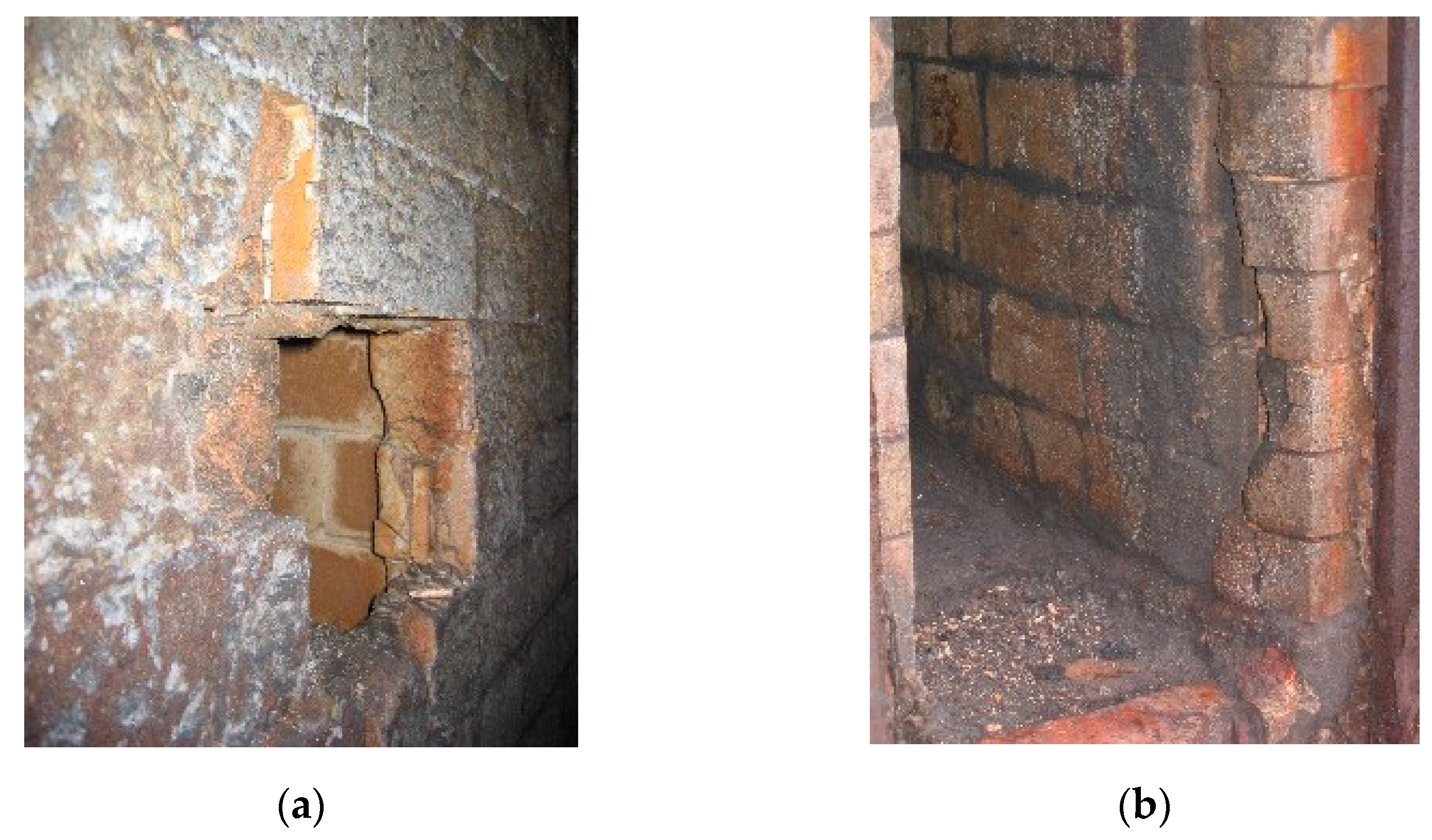
Hard pushes lead to inadequate stress on the walls of the oven during coke removal [18]. This mechanical stress can seriously damage the refractory. At the same time, there is an increased friction of the coke against the refractory walls, increasing the abrasion of the silica material. In addition, if the area of the wall where excessive pressure is produced is a previously repaired or defective zone, its resistance decreases with respect to the rest of the zones of the oven [18]. Figure 2a shows damage on the oven wall caused by hard pushes while Figure 2b shows damage from abrasion or thermal shock.
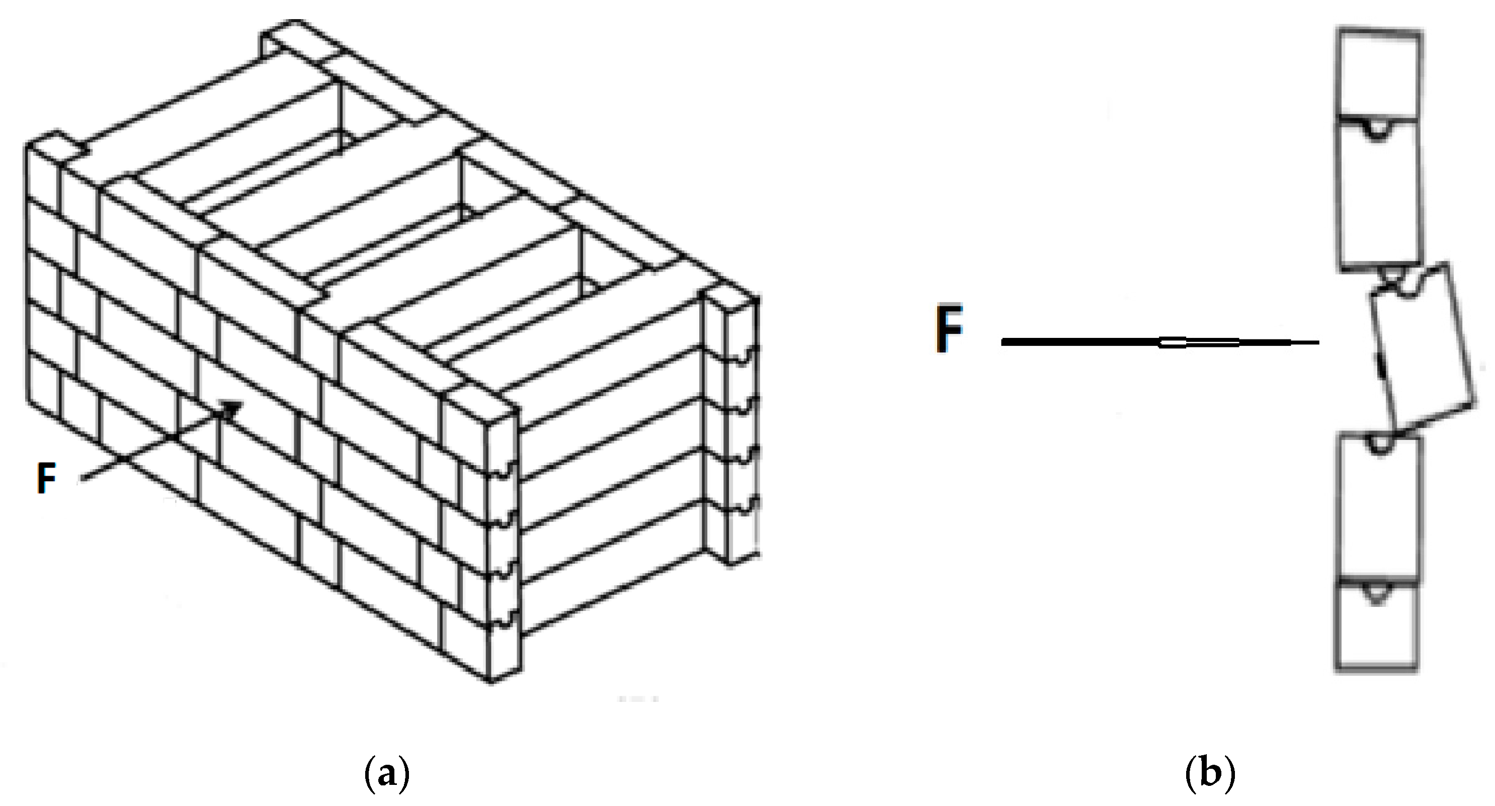
It would be possible to analyze the stress generated by hard pushes using the finite element method, which would permit to calculate their tolerable limit [19]. Figure 3 shows how the force exerted by hard pushes can displace the oven wall refractory.
The mortar joints of refractory pieces (tongue and grooves) are particularly sensitive to this mechanical stress [20].
These are the most common causes of coke extraction difficulty:
  • Inadequate loading of coal mixture.
    If the charge is higher than necessary, not all the coal will be transformed into coke and consequently the needed shrinkage will not occur and greater resistance in the pushing of the oven will be generated [4].
  • Incorrect charge density.
    Coal mixture must contain between 8 and 10 per cent of H2O. A deviation from this rate will affect the charge density and the thermal energy required to transform the coal into coke. Again, the shrinkage of the coke cake may be compromised and lead to a hard pushing [4].
  • Low temperature.
    Incomplete transformation of the coal mixture due to poor heating is one of the most frequent causes of hard pushes. If there is a deficit of thermal energy supplied by the combustion chambers to the coking chambers, the transformation of the mixture of coals into coke will not be carried out completely and, therefore, the reduction and separation of the oven walls will not take place.
  • Hight temperature.
    Excessive energy input into the coke mixture will accelerate the process of transformation into coke, provoking a reduction of coke size in the final stage and making it mechanically less consistent and more difficult to extract.
    Damage to the refractory.
    Deformation or damage to the refractory, which prevents the coke from sliding through the oven, can lead to “hard” pushes, which can also generate damage in other areas of the ovens.
  • Carbon deposits on the oven walls.
    The gas obtained during coking can crack, producing carbon deposits (graphite) on the walls. This graphite turns into an obstacle during the pushing of the oven [4].
  • Deviation in the coking time.
    For a given battery production schedule, there must be a selection of time for the coal to remain in the oven. This time is set precisely, according to the calories provided during combustion, which in turn depends on the average temperature target of the battery. The coking time must be the same for all the ovens. That is, for a given amount of coal, a given oven geometry and a fixed calorific input, the residence time should be equal. This concept is called global coking time (GCT).
    Positive deviation occurs when the charge remains in the oven for a period of time longer than scheduled. In this case the coke undergoes the “high temperature” effect, as stated before. Negative deviation occurs when the charge remains in the oven for a period of time shorter than scheduled, provoking the “low temperature” effect in the coke [4].
  • Inadequate coal mix.
    The mixture must be composed of coals with coking characteristics. This means that, with adequate heating, the cake can contract and separate from the oven walls, facilitating its extraction [21]. If an error has previously occurred in the mixing of the coals, their behavior in the oven will be affected by exerting a high resistance when extracted.

2.1.2. Sticky Ovens (Mechanical Stress, Abrasion and Cooling of Refractory)

The definition of a “sticky oven” is a situation in which it is not possible to extract the coke, due to a high resistance to the pusher ram device [22]. In fact, it is a case of “hard push”, where coke extraction is impossible because of the enormous resistance of the coke cake.
Sticky ovens are provoked by the same factors as hard pushes. However, the impact on the refractory of the furnaces is much more damaging in the case of sticky ovens. As with hard pushes, the refractory may be damaged by mechanical stress and there is also the risk of oven cooling, lowering the temperature of the refractory pieces, with the possibility of sudden changes in volume and consequent breakage and spalling of the bricks.
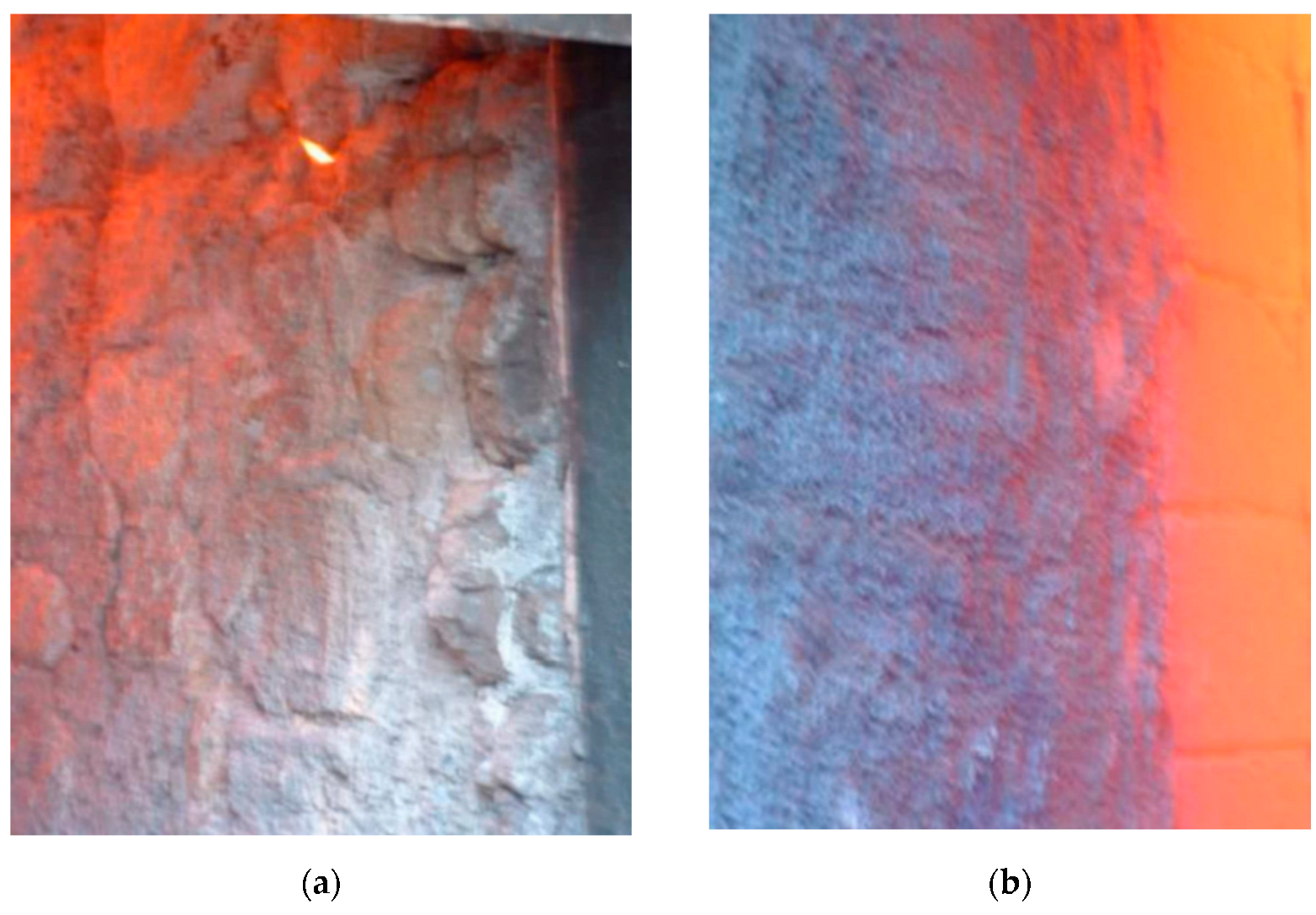
The coke from a sticky oven can only be removed “manually” by opening the doors and extracting it with hand tools. This practice takes a long time to perform, over-exposing the outside areas of the oven to ambient temperature. Silica pieces do not behave properly in the case of thermal shock (see Section 2.2). Although there are refractories with excellent performance if kept at high temperatures, large thermal oscillations are their Achilles heel. Ideally, the refractory must be kept in the thermal range within which tridymite is stable, between 870 °C and 1470 °C [5]. Figure 4a shows the damage caused on the refractory wall by sticky ovens and Figure 4b shows the wall after reparation by ceramic welding.

2.2. Characteristics of Silica Refractories

Silica refractory material is, by definition, the one that has a SiO2 content greater than or equal to 93% [6]. Silica refractory products with SiO2 content higher than 94.5% represent the majority of refractories applied in coke ovens. The rest of their components are Al2O3, CaO, Fe2O3, Na2O + K2O. The characteristics and properties which silica refractories for coke ovens must fulfil are specified in standard DIN 1089 (see Table 1) [23].

2.2.1. Thermal Conductivity

Depending on the area and design of the battery, a wide range of working temperature is acceptable (between 1100 °C and 1300 °C), which makes silica refractories very suitable for use in coke ovens [21].

2.2.2. Refractoriness under Load

Silica bricks have the peculiarity that their softening point (1640 °C) is close to melting point [24]. This characteristic is very positive, as the mechanical properties of the bricks are maintained almost until their melting point (1720 °C).

2.2.3. Cold Compressive Strength

The refractory in coke ovens must be sufficiently robust to withstand:
  • The weight of its own masonry;
  • The charging cars;
  • The weight of the coal;
  • The armatures and metal closures;
  • The efforts exerted in the pushes, especially in the “hard pushes”.
The cold compressive strength of silica refractories for use in batteries is defined by DIN 1089-1 [23] as being greater than 28 MPa.

2.2.4. Expansion

Silica refractories undergo a large expansion up to 870 °C and remain almost constant above that temperature. This is caused by polymorphic transformations due to temperature [5]. This characteristic makes them very attractive for the manufacture of steel coke, since coke ovens always operate at a range of temperature between 1100 °C and 1300 °C.

2.2.5. Thermal Shock Rupture

Thermal shock rupture depends on the coefficient of expansion and stiffness. It varies according to the differences in expansion between the constituents and the temperatures to which they are exposed [5]. Silica refractories are very susceptible to thermal shock rupture due to their high values of expansion at low temperatures. This represents a great disadvantage in comparison with other refractories as chamotte.
In order to save the integrity of the refractory, silica temperatures below 870 °C are not advisable during operation.

2.2.6. Resistance to Chemical Attack

  • The refractory must be resistant to the action of the components of the coal mixture and to the effect of carbon deposits on the oven walls;
  • Silica refractory has a low porosity, <24.5 [6], which helps protection against the salts contained in the coal mixture [5];
  • It has excellent resistance to acid slag;
  • Up to 1550 °C, it has an acceptable resistance to basic slags;
  • It resists well the attacks by iron, ferruginous slags and sodium-calcium glasses [24];
  • In a reducing atmosphere, iron oxide reacts with silica refractory at 1200 °C, producing fayalite (2FeO.SiO2) and damaging the refractory [25]. However, under oxidant conditions the refractory resists FeO perfectly [5].

2.3. Methodology

2.3.1. Data Collection

The data obtained for this study comes from two Didier-designed coke batteries built in the 1970s, each of them formed by 30 ovens. The production rate of each oven was 1.4 pushes per day, that is, 511 pushes per year.
The research covers a two-year period of operation, with the recording of:
  • Hard pushes;
  • Sticky ovens;
  • The scope of repairs to the refractory.

2.3.2. Data Processing

From the data obtained, a comparison was made between the sticky ovens and the hard pushes during the study period on the one hand, and the scope of repairs to their refractory, if any, on the other.
Data collected:
  • Hard pushes
A hard push is defined as a pushing in which the amperage in the motor of the pusher ram is greater than or equal to 310 A.
  • Sticky ovens
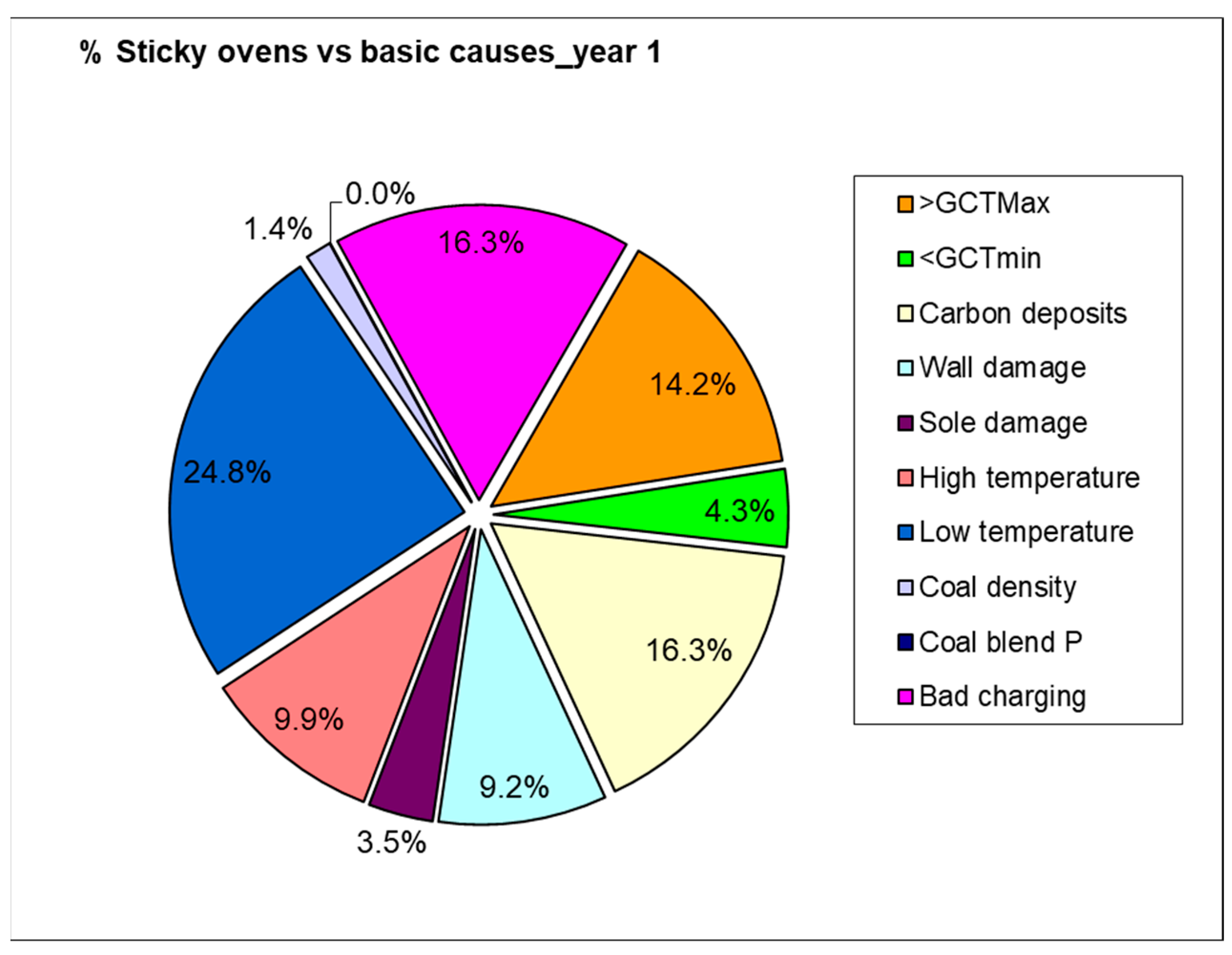
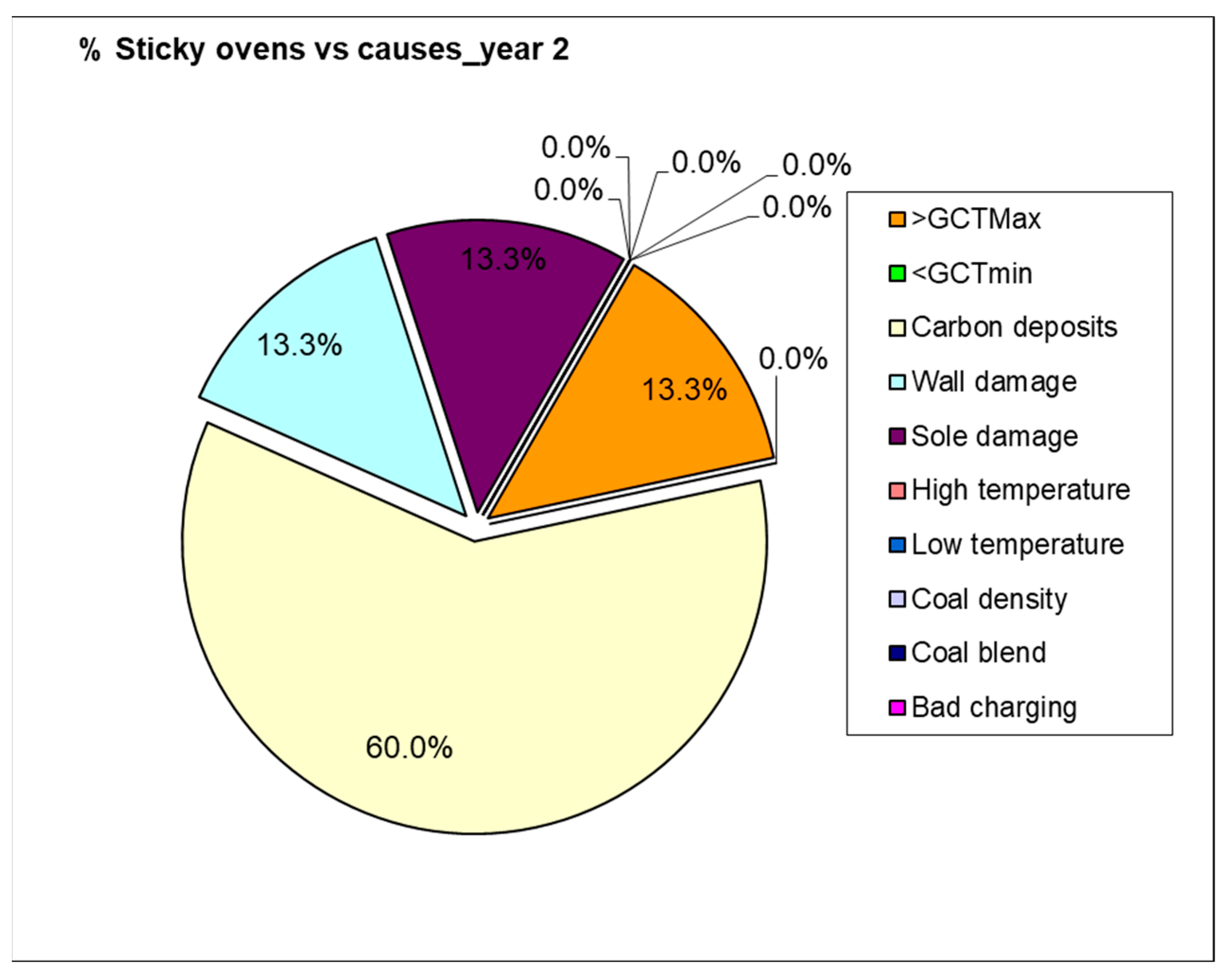
This section deals with those ovens whose load could not be removed with the pusher machine due to the coke being blocked inside them. The reasons are shown in the graphs.
  • Ovens with refractory repairs
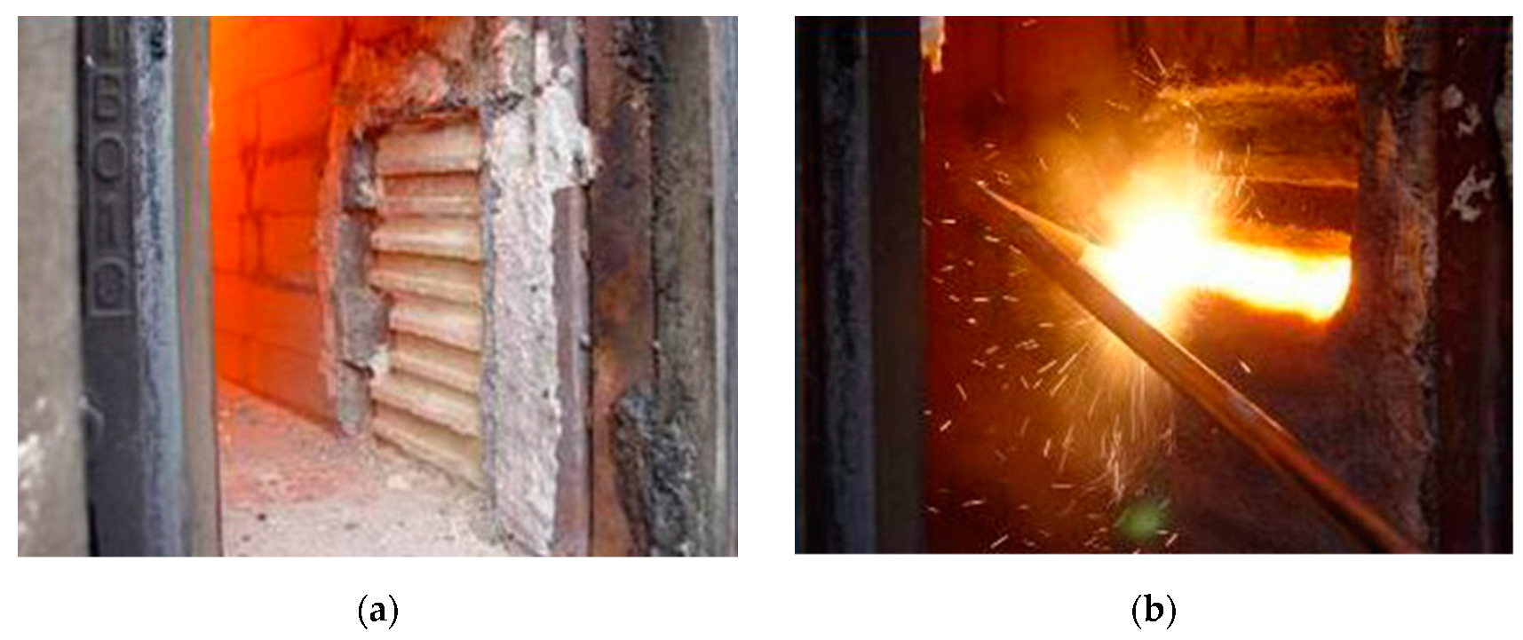
Refractory repairs in the ovens are carried out by ceramic welding and/or replacement of refractory pieces with others made of fused silica, which will be called FSPs (see Figure 5). The scope of repairs with ceramic welding will be quantified by their mass in Kg and that of FSP’s by units.

3. Results

3.1. Hard Pushes

Table 2 below shows the number of times the electrical engine of the pusher ram gave an amperage data above 310 A during coke removal from the ovens. It also reflects the percentage with respect to the total production.

3.2. Sticky Ovens

Table 3 lists the number of sticky ovens in the batteries during the two years of the study and Figure 6 and Figure 7 show the root causes.

3.3. Ovens with Damage (Repaired)

Table 4 shows the scope of refractory repairs in the ovens of both batteries over a period of two years.

3.4. Interpretation of Results

This section will establish the relationship or the possible effects of hard pushes and sticky ovens on the refractory of the furnaces. As mentioned in previous sections, both hard pushes and sticky ovens have a negative impact on silica refractory.
Adequate process control, which minimizes the possibility of sticky ovens or hard pushes, will keep the refractory in operating condition for a longer time.

3.4.1. Hard Pushes Versus Repairs

Figure 8 and Figure 9 show hard pushes versus repaired ovens in battery A.
Comparing the data of the hard pushes with the repairs carried out on the refractory of the corresponding oven, the following conclusions can be drawn:
All the ovens in battery A were exposed to hard pushes: between 3.5% and 11% during the first year; and between 0.8% and 8.8% during the second year.
The ovens where repairs were carried out presented an average of 7.37% of hard pushes during the first year, whereas the average of hard pushes during the second year were 3.65%.
Thus, it can be concluded that the repaired ovens were exposed to a high number of hard pushes.
The second period reveals lower levels of hard pushes in those ovens where repair was carried out.
Figure 10 and Figure 11 show hard pushes versus repaired ovens in Battery B.
All the ovens in battery B were exposed to hard pushes: between 1.4% and 13% during the first year; and between 0.2% and 23.29% during the second year.
The ovens which underwent repairs had an average of hard pushes of 6.75% in the first year and 3.87% in the second year.
The repaired ovens were exposed to a high number of hard pushes.
The second period presented much lower levels of hard pushes in those ovens where repair was carried out.

3.4.2. Sticky Ovens versus Repairs

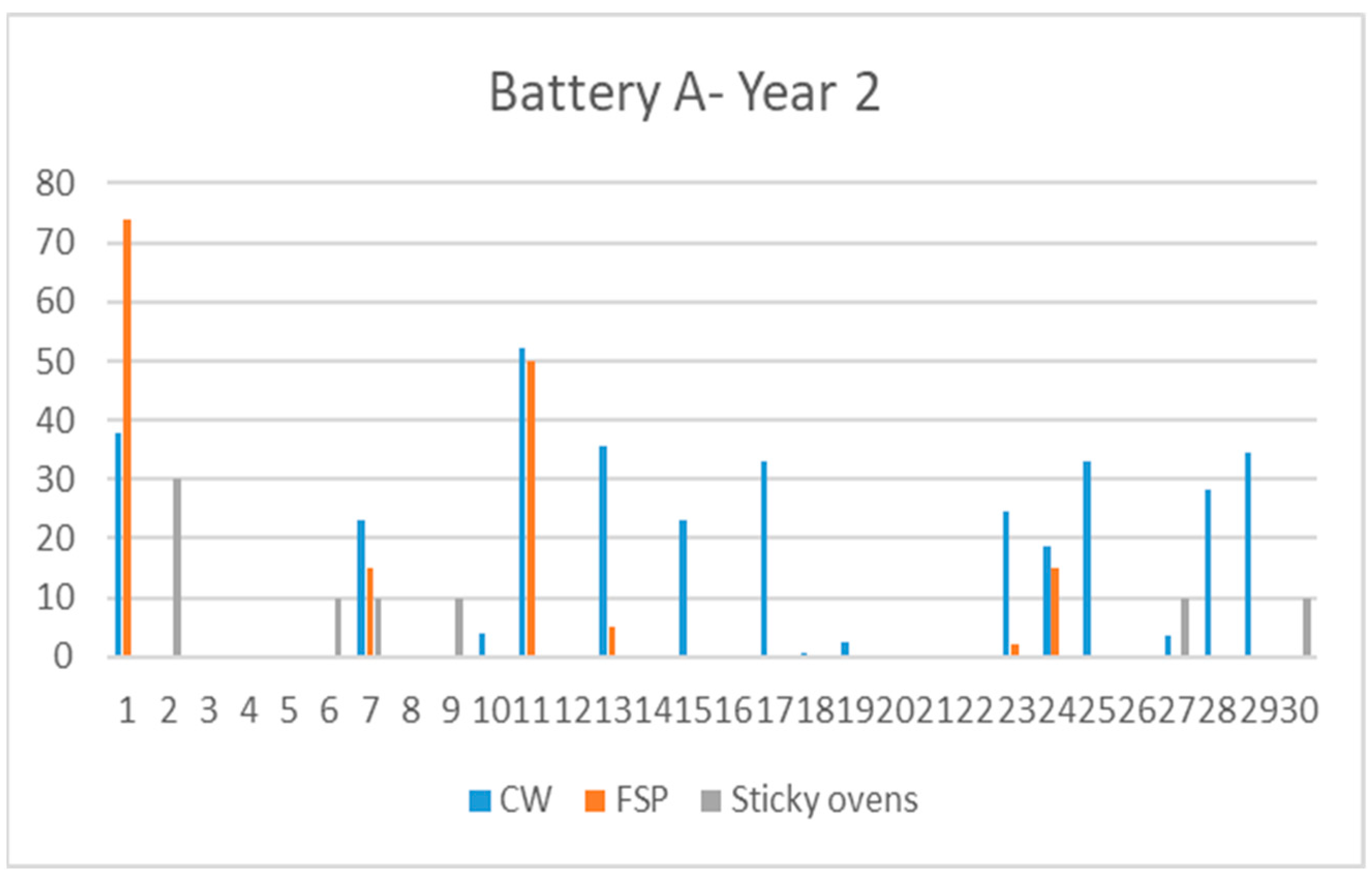
The data from repairs in furnaces in Battery A with previous sticky ovens are as follows (see Figure 12 and Figure 13).
Furnaces with sticky ovens during the study period: 24 (80%).
Furnaces with sticky ovens during the first year: 21 (70%). There were 64 sticky ovens.
Furnaces with sticky ovens during the second year: six (20%). There were eight sticky ovens, three of them in furnace A2.
The majority of sticky ovens occurred during the first year: 88.9% of the total.
Furnaces with sticky ovens during the two years of study: three (10%). Furnaces A2, A7 and A27.
Furnaces with a high number of sticky ovens: A2 (10), A11 (9), A12 (4), A13 (4), A14 (14) and A28 (4).
Ovens with repairs in both years:
A1 had a major repair in the second year. The repair carried out in the first year was prior to the date of the sticky oven.
A7 was repaired in the second year by ceramic welding and replacement of parts with FSP’s.
A11 suffered nine sticky ovens and was repaired in the second year by ceramic welding (5.3 tons and 55 FSP’s).
A13 presented four sticky ovens, 3.55 tons and five FSP’s during the second year.
A15 was repaired with 2.3 MT, with no previous sticky ovens.
A17 had one major repair and no previous sticky ovens.
A23: the repair in the second year was greater than the one in the first year.
A28: the repair in the second year was greater than the one in the first year.
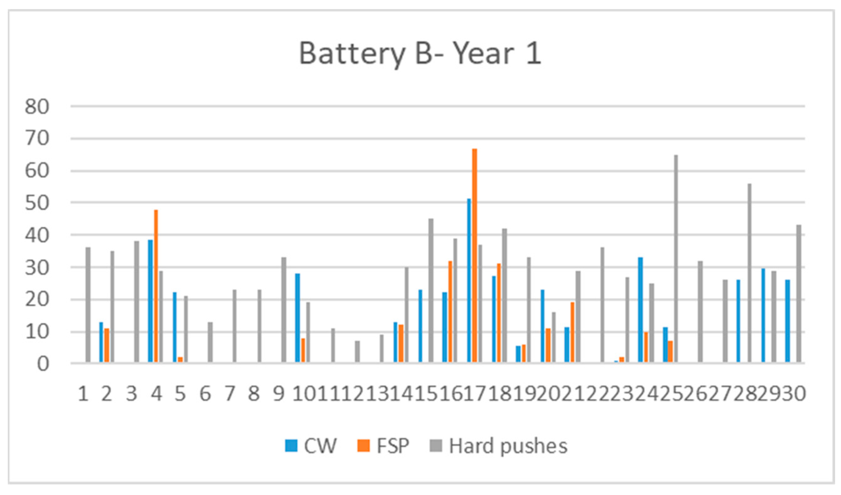
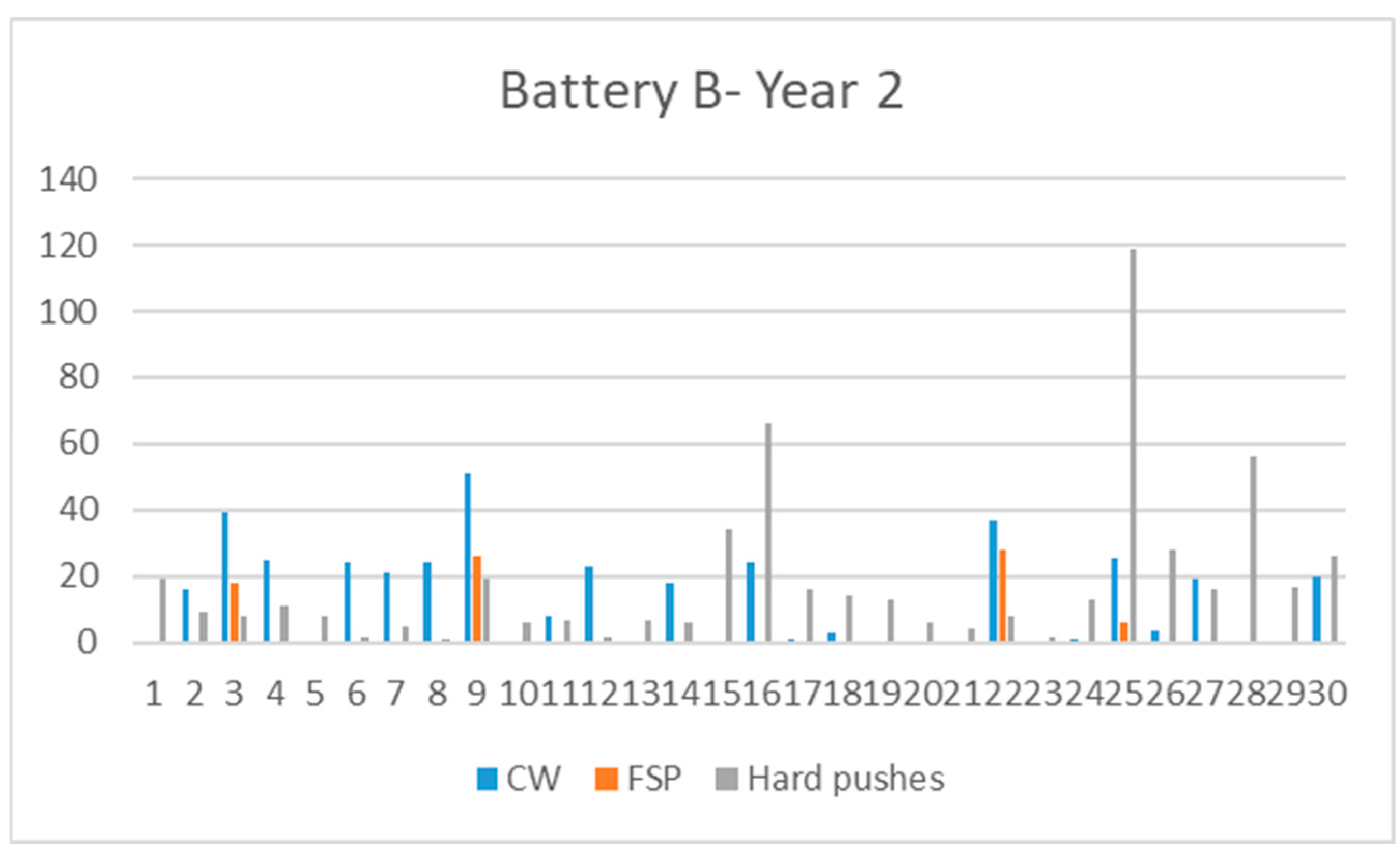
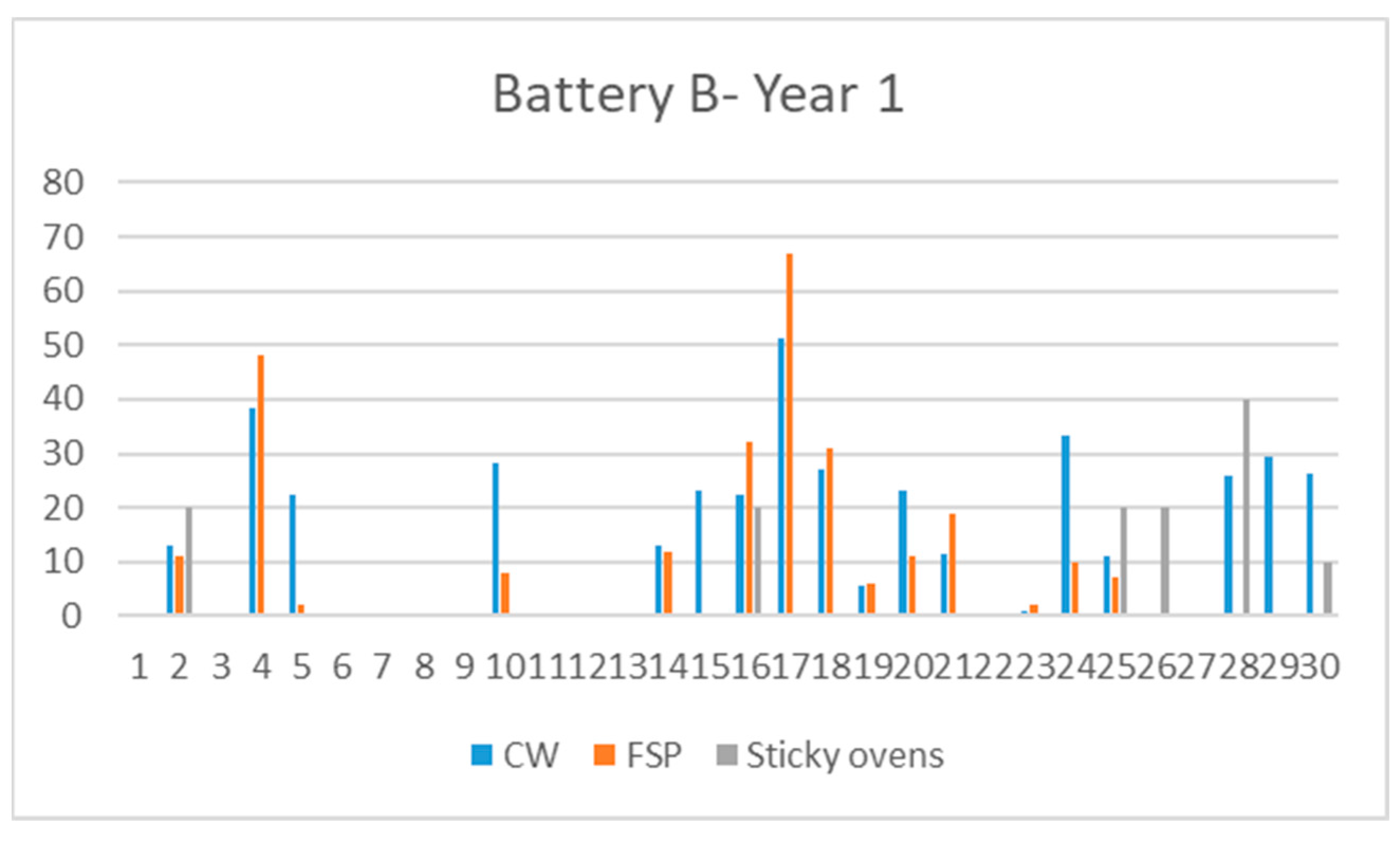
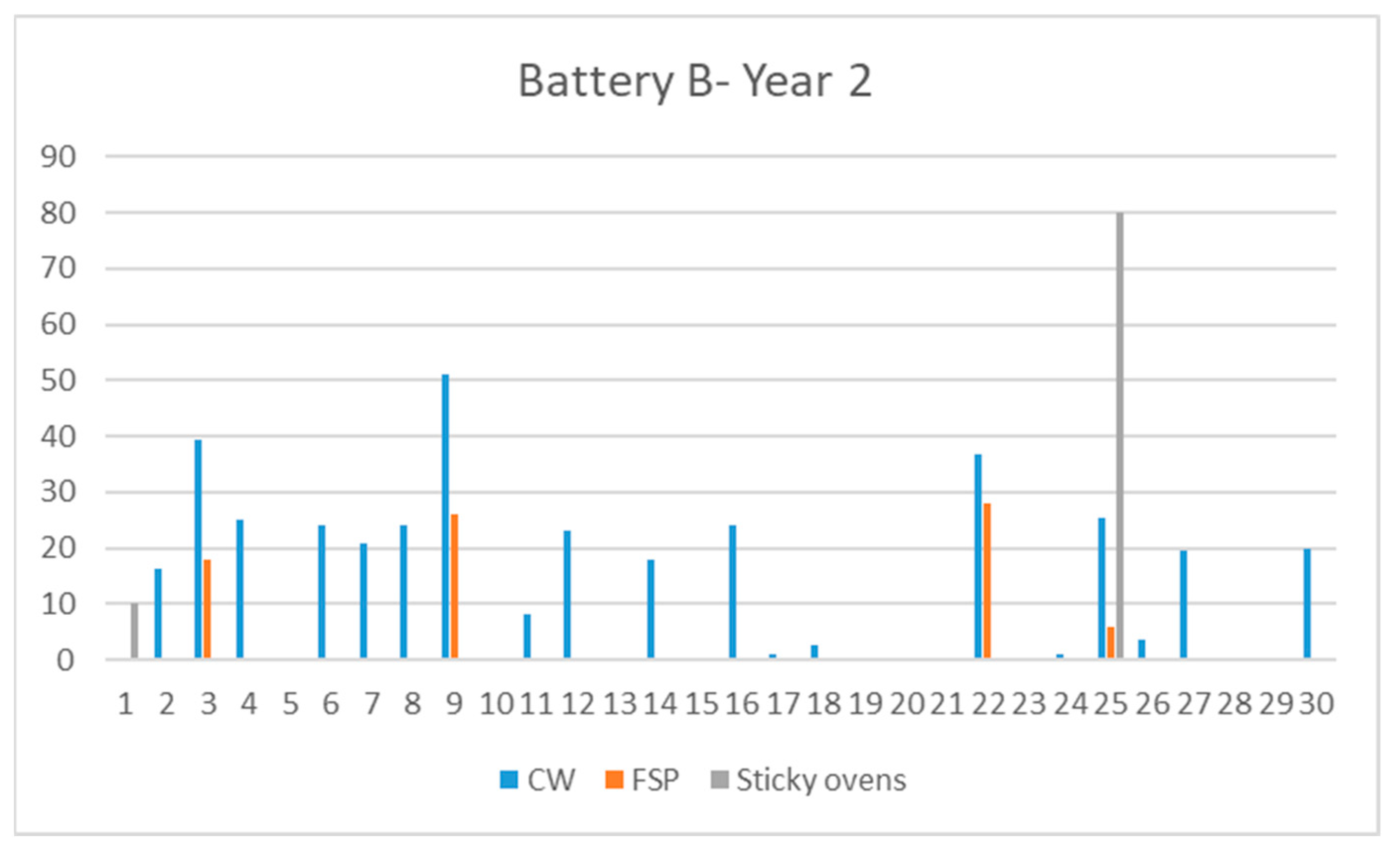
The data from repairs in furnaces in Battery B with previous sticky ovens are as follows in Figure 14 and Figure 15.
Furnaces with sticky ovens during the study period: 7 (23.3%).
Furnaces with sticky ovens during the first year: six (20%). There were 13 sticky ovens.
Furnaces with sticky ovens during the second year: two (6.6%). There were nine sticky ovens, 8 of them in furnace B25.
The majority of the sticky ovens occurred during the first year: (59.1% of the total). Oven B25 underwent almost all of the sticky ovens during the second year.
Furnace with sticky ovens in both years of study: one (3.3%). Oven B25.
Furnaces with a high number of sticky ovens: B25 (10), B28 (4).
Ovens with repairs in both years:
B2 underwent repair in the second year after having two sticky ovens in the previous year.
B4 received a major repair in the first year and needed repair in the second year, although it had not presented previous sticky ovens.
B16 was repaired in the second year, after having two sticky ovens in the previous year.
B14, B17, B18 and B24 were repaired in the second year, with no previous sticky ovens.
B25 was repaired in the second year, after having two sticky ovens in the previous year and 8 in the second year.
B30 was repaired in the second year, after having one sticky oven in the previous year.
The following ovens only had repairs in the second year: B3, B6, B7, B8, B9, B11, B12, B22, B26 and B27.
Only B26 had suffered sticky ovens in the previous year. In addition, B3 and B09 had received major repair.

4. Discussion

The data obtained in this study refer to two years of operation of two coke batteries. The data collected show a trend in the behavior of the refractory of the ovens. It is important to clarify that the refractory material of these ovens has been affected by the sticky ovens and hard pushes, not only during these two years, but also during their entire operating life. At the same time, there are also other factors for which no data have been collected, which can affect the integrity of the refractory, such as incorrect operations, impacts due to errors, etc. That said, this period does prove the influence of these phenomena on the refractory lining of coke ovens.
Batteries are designed with over-dimensioned margins in terms of mechanical resistance to counteract the stress suffered by the walls in the pushes. However, during the operation of the ovens, the mortar used to bind the refractory pieces is gradually lost and, as a result, their mechanical stability decreases, leaving the walls of the ovens more vulnerable to the hard pushes. At the same time, the areas repaired with ceramic welding lose mechanical strength compared to the original lining, and they are less able to withstand hard pushes.
The data tells us that, in general, ovens exposed to less hard pushes have less damage on their refractory.
Hard pushes are reduced after the repair of a wall by ceramic welding or even with pieces of fused silica. This permits to eliminate deformations in the oven wall and oven soles, which represent one of the main causes of hard pushes, guaranteeing their reduction in the future.
The data also shows that the effect is not immediate, as there are ovens with hard pushes which did not need to be repaired until the following year. Nor is it proportional, that is, more hard pushes do not mean more damage; it is rather a question of how hard the pushes are.
In all, 95% of the ovens suffered sticky ovens. The majority of them underwent reparation during the two years of study. The other 5% of the ovens had either received major repair in the previous period or received it in the following period.
The negative effects of sticky ovens are not immediate, but they usually appear with a delay. The drop in temperature during removal of coke can provoke the proliferation of cracks, which may weaken the structure.
As with hard pushes, not all the sticky ovens have the same consequences. If extended over time, the manual removal process will overexpose the oven refractory to ambient temperature, with a higher risk of lining degradation.

5. Conclusions

The data obtained demonstrate the impact of hard pushes, and sticky ovens in particular, on the integrity of silica refractory.
Hard pushes cause mechanical failure on the refractory of the furnaces, even the tolerable limit of the mechanical strength of the wall is not reached.
The results of the research show that sticky ovens cause failure to silica bricks due to thermal shock.
The highest incidence on the integrity of refractory is due to sticky ovens. From this fact, it can be concluded that the exposure of the refractory to thermal shock is more damaging than the mechanical stress of hard pushes.
Coke plant managers should guide their process to avoid these circumstances as much as possible. An important issue regarding sticky ovens, which does not appear in the literature, is the proper procedure to use. When a sticky oven occurs, “manual” removal of the coke from the oven is necessary. In this process, the refractory is exposed to environment temperature for longer than usual. In this case, plant managers must proceed rigorously in order to minimize heat losses as much as possible.
The findings of this paper may help plant managers to extend the useful life of Coke batteries.

Author Contributions

Conceptualization, M.G.G. and D.Á.L.; methodology, M.G.G. and D.Á.L.; validation, D.Á.L. and M.G.G.; data curation, D.Á.L.; writing—original draft preparation, D.Á.L.; writing—review and editing, D.Á.L. All authors have read and agreed to the published version of the manuscript.

Funding

This research received no external funding.

Institutional Review Board Statement

Not applicable.

Informed Consent Statement

Not applicable.

Data Availability Statement

Not applicable.

Conflicts of Interest

The authors declare no conflict of interest.

References

  1. Nashan, G.; Rohde, W.; Wessiepe, K. Some figures and facts on the present status and new proposals for a future oriented cokemaking technology. Cokemak. Int. 2002, 12, 50–55. [Google Scholar]
  2. Gudenau, H.W.; Senk, D.; Fukada, K.; Babich, A.; Froehling, C.; García, L.L.; Formoso, A.; Alguacil, F.J.; Cores, A. Coke, char and organic waste behaviour in the blast furnace with high injection rate. Rev. Metal. 2003, 39, 367–377. [Google Scholar] [CrossRef] [Green Version]
  3. Álvarez, R.; García-Cimadevilla, J.L.; Díez, M.A.; Barriocanal, C. La tecnología de producción de coque de horno alto ante el nuevo milenio. Rev. Metal. Madrid Vol. Extr. 2005, 41, 29–34. [Google Scholar] [CrossRef]
  4. Lorenzo, E.; García, J. Manual de Hornos de Cok y Subproductos; Empresa Nacional siderúrgica, S.A.: Avilés, España, 1989. [Google Scholar]
  5. Pérez, E. Materiales refractarios para hornos de coque. Boletín Inf. Inst. Nac. Carbón (INCAR) 1955, 4, 231–250. [Google Scholar]
  6. UNE-EN 12475-1:1998; Clasificación de los Productos Refractarios Conformados Densos. Parte 1: Productos Sílico-Aluminosos. Comité Europeo para la Estandarización: Brussels, Belgium, 1998.
  7. Brunk, F. Silica bricks for modern coke oven batteries. Cokemak. Int. 2000, 14, 37–40. [Google Scholar]
  8. Córdova, M.; Madias, J. Coke Oven Life Prolongation. A Multi-Disciplinary Approach. In Proceedings of the 45th Ironmaking, 16th Iron Ore, Part of the ABM Week, Rio de Janeiro, Brazil, 17–21 August 2015. [Google Scholar]
  9. Lee, W.; Lee, Y. Internal gas pressure characteristics generated during coal carbonization in a coke oven. Energy Fuel 2001, 15, 618–623. [Google Scholar] [CrossRef]
  10. Crelling, J.C.; Suárez-Ruiz, I. The role of petrology in coal utilization. In Applied Coal Petrology; Elsevier: Amsterdam, The Netherlands, 2008; pp. 173–192. [Google Scholar]
  11. Harris, W. The reaction of coal ash with coke oven bricks. Ironmak. Proc. Metall. Soc. 1987, 45, 475–478. [Google Scholar]
  12. Ishikawa, Y. Operational Strategy for Coke Ovens in Japan; World Steel Association: London, UK, 1985; pp. 88–96. [Google Scholar]
  13. Arcuri, S.; Cordova, M.; Traglia, M. Improvements at SIDERAR´s coke oven batteries to extend their useful life. In Proceedings of the 60th Ironmaking Conference, Baltimore, MD, USA, 25–28 March 2001. [Google Scholar]
  14. Kelling, A. Continuous development for a longer battery life at the Rautaruukki Steel Coking Plant in Raahe. In Proceedings of the AISE Annual Convention and Exposition, Finland; 2001; pp. 1–22. [Google Scholar]
  15. Komaki, I.; Matsuo, T.; Kogushi, Y.; Nishimoto, K.; Yamamoto, H. Coke oven diagnosis and repair techniques. In Proceedings of the 60th Ironmaking Conference, Baltimore, MD, USA, 25–28 March 2001; pp. 595–605. [Google Scholar]
  16. Álvarez, J.M. Manual de Carbones; Empresa Nacional Siderúrgica S.A.: Avilés, España, 1990. [Google Scholar]
  17. Badiuzzamah, M. Design Optimization of Coke Pusher Ram; Mcmaster University: Hamilton, ON, Canada, 1969. [Google Scholar]
  18. Shimoyama, I.; Yamamoto, T.; Fukada, K. Tolerable Limit of Localized Force on Damaged Coke Oven Wall Analyzed by Discrete Element Method. ISIJ Int. 2010, 50, 1048–1053. [Google Scholar] [CrossRef] [Green Version]
  19. Gayle, J.B.; Eddy, W.H. Carbonizing Test with Tuscaloosa oven Studies of Pushing Pressures; US Dept. of the Interior, Bureau of Mines: Washington, DC, USA, 1961. [Google Scholar]
  20. Ruecki, R. Refractories Handbook; Schacht, C.A., Ed.; Marcel Decker Inc.: New York, NY, USA, 2004. [Google Scholar]
  21. Shinohara, Y. Refractories Handbook; Japanese Association of Refractories: Tokyo, Japan, 1998. [Google Scholar]
  22. Jordan, P. Development of Small Scale Techniques Used to Study Coking Pressure Generation; Loughborough University of Technology: Loughborough, UK, 1992; p. 26. [Google Scholar]
  23. Norma DIN 1089-1 (1995); Refractarios para uso en Hornos de Coke. Parte 1: Ladrillos Silíceos, Requisitos y Ensayos. DIN Instituto Alemán Para la Normalización: Berlin, Germany, 1995.
  24. De Aza, S. Jornadas Técnicas sobre el Diseño, Propiedades y Aplicaciones de los Materiales Refractarios; UAM: Madrid, Spain, 2004. [Google Scholar]
  25. Nomura, S.; Terashima, H.; Sato, E.; Naito, M. Some Fundamental Aspects of Highly Reactive Iron Coke Production. ISIJ Int. 2007, 47, 823–830. [Google Scholar] [CrossRef]
Figure 1. Friction of the coke cake on the oven walls.
Applsci 12 13015 g001
Figure 2. (a) Hole produced by hard pushes; (b) damage in the refractory produced by thermal shock.
Applsci 12 13015 g002
Figure 3. (a) Load exerted by the coke cake; (b) breakage of the oven wall.
Applsci 12 13015 g003
Figure 4. (a) Wall with damage on the refractory; (b) refractory repaired by ceramic welding.
Applsci 12 13015 g004
Figure 5. (a) Repair by fused silica pieces; (b) ceramic welding on refractory pieces.
Applsci 12 13015 g005
Figure 6. Causes of sticky ovens in the first year.
Applsci 12 13015 g006
Figure 7. Causes of sticky ovens in the second year.
Applsci 12 13015 g007
Figure 8. Hard pushes and refractory repairs battery A, year 1.
Applsci 12 13015 g008
Figure 9. Hard pushes and refractory repairs battery A, year 2.
Applsci 12 13015 g009
Figure 10. Hard pushes and refractory repairs battery B, year 1.
Applsci 12 13015 g010
Figure 11. Hard pushes and refractory repairs battery B, year 2.
Applsci 12 13015 g011
Figure 12. Sticky ovens and refractory repairs battery A, year 1.
Applsci 12 13015 g012
Figure 13. Sticky ovens and refractory repairs battery A, year 2.
Applsci 12 13015 g013
Figure 14. Sticky ovens and refractory repairs battery B, year 1.
Applsci 12 13015 g014
Figure 15. Sticky ovens and refractory repairs battery B, year 2.
Applsci 12 13015 g015
Table 1. Characteristics of silica refractories.
ParameterUnitValue
SiO2%≥94.5
Al2O3%≤2.0
Fe2O3%≤1.0
CaO%≤3.0
Na2O + K2O%≤0.35
Apparent porosity%≤24.5
Cold compressive strengthN/mm2≥28
Refractoriness under load°C≥1640
Densityg/cm31.82
Linear thermal expansion%1.26
Residual quartz%1.5 ± 0.5
Table 2. Hard pushes in the period of study.
Year 1Year 2 Year 1Year 2
Oven%%Oven%%
A1367132.5B1367193.72
A25110438.4B2356.891.76
A3377.2265.1B3387.481.57
A45411244.7B4295.7112.15
A5448.6316.1B5214.181.57
A6336.5316.1B6132.520.39
A7326.3305.9B7234.550.98
A8305.9458.8B8234.510.20
A9305.9224.3B9336.5193.72
A10387.4397.6B10193.761.17
A11448.6285.5B11112.271.37
A12316.191.8B1271.420.39
A13295.781.6B1391.871.37
A14418203.9B14305.961.17
A15367214.1B15458.8346.65
A165110336.5B16397.66612.92
A17438.4183.5B17377.2163.13
A18305.940.8B18428.2142.74
A19265.1122.3B19336.5132.54
A20183.591.8B20163.161.17
A21428.2173.3B21295.740.78
A22265.181.6B2236781.57
A23397.691.8B23255.320.39
A24367102B24254.9132.54
A25479.2356.8B25651311923.29
A26458.8203.9B26326.3285.48
A275711142.7B27265.1163.13
A28489.4214.1B2856115610.96
A29316.1214.1B29295.7173.33
A30326.3122.3B30438.4265.09
Table 3. Sticky ovens in the period of study.
Year 1Year 2 Year 1Year 2
OvenOven
A11 B1 1
A273B22
A3 B3
A43 B4
A51 B5
A6 1B6
A711B7
A82 B8
A9 1B9
A10 B10
A119 B11
A124 B12
A134 B13
A1414 B14
A15 B15
A161 B162
A17 B17
A18 B18
A191 B19
A20 B20
A213 B21
A222 B22
A231 B23
A241 B24
A252 B2528
A261 B262
A2711B27
A284 B284
A291 B29
A30 1B301
Table 4. Repaired ovens in the period of study by ceramic welding and FSP.
Year 1Year 2 Year 1Year 2
OvenCWFSPCWFSPOvenSCFSPCWFSP
A12625 385074B10 0
A2 B21300111625
A31875 B30 392518
A427255 B43850482500
A5382526 B5222520
A632754 B60 2400
A71025 237515B70 2100
A89004 B80 2400
A920503 B90 512526
A102425 400 B10282580
A112575 532555B110 825
A1239507 B120 2300
A131150 35505B130 0
A142225 B141300121800
A15170062325 B152300 0
A16330072 B162225322425
A175450703325 B17512567100
A18750475 B18272531275
A1975 25 B1955060
A2019006 B202325110
A211650 B211150190
A22340010 B220 367528
A23125224502B237520
A24 187515B24332510100
A25 3325 B251125725506
A26650 B260 350
A270 375 B270 1950
A281475152825 B282600 0
A29 3450 B292950 0
A30 B302625 2000
Publisher’s Note: MDPI stays neutral with regard to jurisdictional claims in published maps and institutional affiliations.