Article

Semi-Active Control of Seismic Response on Prestressed Concrete Continuous Girder Bridges with Corrugated Steel Webs

1
School of Civil Engineering and Architecture, East China Jiaotong University, Nanchang 330013, China
2
School of Civil Engineering, Wuhan University, Wuhan 430072, China
*
Author to whom correspondence should be addressed.
Appl. Sci. 2022, 12(24), 12881; https://doi.org/10.3390/app122412881
Submission received: 26 October 2022 / Revised: 13 December 2022 / Accepted: 13 December 2022 / Published: 15 December 2022

Abstract

:
To improve the seismic capacity of prestressed concrete (PC) continuous girder bridges with corrugated steel webs (CSWs), suitable damping control measures can be used to effectively reduce the seismic response of the bridge. Based on the semi-active control theory, the semi-active control system of a three-span PC continuous girder bridge with CSWs is designed, and the semi-active control system program of the three-span PC continuous girder bridge with CSWs is compiled by MATLAB. The time–history curves of damper energy consumption of active optimal control algorithm and three different semi-active control algorithms are compared and analyzed, as are the time–history curves of main girder displacement, acceleration, and pier internal force with or without semi-active control. The study shows that the rational determination of the weight matrix coefficient can make the active control achieve a better vibration absorption effect and economy. The semi-active control algorithm of Hrovat has the best vibration absorption effect, which is closest to that of the active optimal control algorithm. Under the state of semi-active control, the average vibration absorption rate of displacement and acceleration of the main girder with CSWs are 71% and 20%, respectively. The time–history curve of bending moment and shear force in the pier bottom is similar, and the average vibration absorption rate of bending moment and shear force at the bottom of pier #2 is 70%. At the same time, the average vibration absorption rate of bending moment and shear force at the bottom of pier #3 is between 42% and 48%. The semi-active control measure has a good vibration absorption effect on the overall seismic response of the PC continuous girder bridges with CSWs. This study provides a certain reference for the seismic reduction and isolation design of composite structure bridge with CSWs.

1. Introduction

As a new type of composite structure, the prestressed concrete (PC) girder bridge with corrugated steel webs (CSWs) was invented in France in the 1980s. The concrete webs of traditional concrete box girders are replaced by CSWs, which brings some better changes in structural performance [1], such as significantly reducing the structural weight, avoiding the problem of box girder web cracking, and increasing prestress efficiency. Because of the good completion, this composite structure has gained great attention from researchers and bridge engineers. In recent years, many scholars have performed research on the mechanical properties of composite box girders with CSWs, including mainly the static performance, such as flexural properties [2,3], shear performance [4,5,6,7], and torsion performance [8,9,10]. Some studies on dynamic properties have also been performed [11,12,13,14], and researchers have also studied the mechanical analysis of the construction stage [15,16]. These important results provide a theoretical basis on the promotion and application of this new type of composite structure.
In recent years, the frequency of earthquakes has caused varying degrees of damage to bridges [17]. In 2008, the U.S. Department of Transportation surveyed the causes of bridge failures, and 19 of 1746 bridge failures in 18 states were due to earthquakes. However, the focus of this survey only counted collapses and did not collect information on the extent of damage caused by earthquakes, the extent of traffic disruption, the detours, and repair costs [18]. Based on this, by taking effective seismic control measures, the seismic performance of bridges can be effectively improved and personal and property losses can be reduced.
There are many methods for improving the seismic performance of bridges—the passive control method and the semi-active control method are commonly used. The passive control method mainly considers the general characteristics of ground motion and reduces the seismic energy experienced by the structure so as to reduce the seismic response of the main structure. The main methods include the energy dissipation damping method and the basement isolation method. The energy dissipation damping method can effectively improve the seismic performance of old bridges [19]. The base-isolation method can effectively improve the seismic performance of the bridge structure and take into account the uncertainty of the structural plane [20]. Semi-active control is a control method between active and passive control. Semi-active control has both the reliability and economy of passive control and the strong adaptability of active control with low maintenance requirements [21]. Therefore, seismic control methods based on semi-active control have been widely applied in the design of seismic control of bridge structures. In the past 30 years, magnetorheological (MR) dampers have been widely used for semi-active control because of their low energy consumption, high damping force, and fast response. The research results of MR-damper-based seismic testing of bridges by Dyke S J et al. [22], Sheikh et al. [23], and Guo et al. [24] are widely recognized by scholars in the field of seismic research. Sheikh et al. [23] applied the bang–bang control algorithm to the semi-active control of reinforced concrete girder bridges for seismic resistance, and the study showed that the control algorithm has a good seismic reduction vibration absorption effect. Sahasrabudhe et al. [25] used semi-active control to experimentally analyze the seismic response of a 1:20 scale bridge model and pointed out that semi-active control can effectively reduce the seismic response of the bridge and thus improve its seismic performance. Ok et al. [26] proposed a fuzzy control algorithm to improve the seismic performance of a cable-stayed bridge which improves seismic performance by determining the input voltage from the response of MR dampers, and the simulation results showed that the semi-active fuzzy control algorithm can effectively improve the seismic performance of cable-stayed bridges. Lin et al. [27] performed numerical simulations of a large-span structure based on a semi-active control algorithm in the trust domain and pointed out the potential effectiveness of semi-active control for seismic control of large-span structures. Ei-Khoury et al. [28] performed seismic tests on a three-span bridge and proposed a semi-active control algorithm based on optimal polynomial control that can achieve a balance between multiple objectives with low energy consumption. Heo et al. [29] proposed a hybrid control algorithm that could improve the performance of two separate control algorithms, which effectively improved the seismic performance of a multi-span bridge.
It is clear from the above literature that the application of semi-active control in bridge seismic control is feasible and effective. Compared with conventional prestressed concrete box girder bridges, PC composite girder bridges with CSWs are widely used in seismic-prone areas due to their lower self-weight and better seismic performance. However, how good is the performance of semi-active control in the seismic performance of such composite structure bridges, and can it significantly reduce their seismic response? There are no reports on the application of semi-active control methods in PC composite girder bridges with CSWs. This paper will carry out research of the semi-active control method in this composite girder bridge, and the research results will provide some reference for the design of seismic reduction of this composite structure.

2. Semi-Active Control Theory

2.1. Controlled System Status Description

In this paper, a three-span composite continuous girder bridge with CSWs equipped with r semi-active controllers was studied assuming an actively controlled structural system with n degrees of freedom. Under the action of external excitation F ( t ) , the equations of motion of the composite structure are expressed as follows:
M X ¨ ( t ) + C X ˙ ( t ) + K X ( t ) = H F ( t ) + E U ( t )
where M , C , and K are the mass matrix, damping matrix, and stiffness matrix of the structure, respectively. X ( t ) is the displacement vector of the structure. X ˙ ( t ) is the velocity vector of the structure. X ¨ ( t ) is the acceleration vector of the structure. U ( t ) is the control force vector. E is the control force position matrix. F ( t ) is the external excitation vector. H is the position matrix of the external excitation vector. For the equation of motion expressed in Equation (1), the equation of state for vibration control can be expressed as
Z ˙ ( t ) = A Z ( t ) + B U ( t ) + W F ( t )
where Z = { X , X ˙ } is a 2n-dimensional state vector. A = [ O I M 1 K M 1 C ] is 2n × 2n-order system matrix. I is an n × n -order identity matrix. B = [ 0 M 1 E ] is the 2n × r-order control device position matrix, and W = [ O M 1 H ] is the seismic action matrix.

2.2. LQR Optimal Active Control Algorithm

Active control algorithm is not only the basis of active control of structural vibration, but also an important part of the construction of semi-active control system. There are mainly the following algorithms: quadratic optimal control algorithm (LQR), instantaneous optimal control algorithm (LQG), robust control algorithm and modal control algorithm, etc. In this paper, the optimal control algorithm (LQR) is used according to the algorithm theory, and the quadratic index performance function is defined as
J = 1 2 t 0 [ Z T Q Z + U T R U ] d t
where t 0 is the earthquake duration, Q is a 2n × 2n-dimensional semi-positive definite state vector weight matrix, and R is an r × r-dimensional positive definite control force vector weight matrix. The form of the weight matrix Q and R can be taken as the form: Q = α [ K 0 0 M ] , R = β I , where α and β are constants to be determined, and the optimal active control force U ( t ) can be calculated by regulating the performance target weight matrices Q and R .
The objective of classical linear optimal control is to minimize the objective function represented by (3) subject to the constraints of the structural equations of motion (1) and state Equation (2), thus seeking the optimal control force vector U ( t ) , for which the Hamiltonian function is introduced.
H = [ Z T Q U + U T R U ] + λ T [ A Z + B U Z ˙ ]
According to the extreme value condition, it can be found that
U ( t ) = G Z ( t ) = R 1 B T P Z ( t )
where G is the feedback gain matrix. The value of the matrix P can be obtained by solving the following Riccati equation.
P A + A T P P B R 1 B T P + Q = 0
Substituting the above equation into the equation of state (2) yields:
Z ˙ = ( A B R 1 B T P ) Z ( T ) + W F ( t )
Equation (7) is the equation of state of the structural vibration control system after adopting LQR.

2.3. Semi-Active Control Algorithm

Semi-active control algorithms are the core of structural semi-active control. Summarizing the more commonly used semi-active control algorithms, there are two main types: (1) switching type, such as simple bang–bang control algorithm, optimal bang–bang control algorithm, and maximum switching control algorithm. (2) Continuity, such as bounded bang–bang control algorithm, bounded sliding control algorithm, and bounded Hrovat optimal control algorithm. The following is a brief description of the three algorithms for comparative analysis in this paper.
1.
Simple bang–bang control algorithm
The output force of the MR damper can be expressed as
f d = c d x ˙ d + f d v s g n ( x ˙ d )
where x ˙ d is the relative velocity of the MR damper; c d is the viscous damping coefficient of the MR damper, and f d v is adjustable Coulomb damping force of the MR damper.
Then, the simple bang–bang algorithm (semictrl1) can be expressed as
u d ( t ) = {   f d m a x   ( x x ˙ ) > 0   f d m i n   ( x x ˙ ) 0  
where x = x d is the relative displacement of the MR damper, and this control algorithm indicates the maximum damping force (fdmax) that can be achieved by applying the damper when the MR damper location is vibrating away from the equilibrium point and the minimum damping force (fdmin) otherwise.
2.
Optimal bang–bang control algorithm
The optimal bang–bang algorithm (semictrl2) can be expressed as
u d ( t ) = { f d m a x   ( u x ˙ ) < 0 f d m i n   ( u x ˙ ) 0  
The equation represents the maximum damping force that can be achieved by applying the damper when the optimal control force is in the opposite direction of the vibration at the location of the MR damper. Otherwise, the minimum damping force is applied. The algorithm exactly reflects the fact that the MR damper applies only the force that prevents the structure from moving but not the force that drives the structure.
3.
Bounded Hrovat control algorithm
The bounded Hrovat algorithm (semictrl3) can be expressed as
u d ( t ) = { f d m a x   ( u x ˙   < 0   a n d   | u | > u d m a x ) | u | s g n ( x ˙ )   ( u x ˙ < 0   a n d   | u | < u d m a x ) f d m i n   ( u x ˙ 0 )  
where u d m a x = c d | x ˙ | + f d v m a x is the maximum damping force that can be achieved by the MR damper relative to the active optimal control force at the moment u ( t ) . Based on the optimal bang–bang control algorithm, the Hrovat semi-active control force ( | u | s g n ( x ˙ ) ) is added to the range of Coulomb damping force that can be realized by MR damper, which is the middle part of the equation.
It should be noted that the relationship between the semi-active control force u i s ( t ) and the semi-active damping force f i d ( t ) is u ( t ) = f ( t ) . The damping force of the MR damper is f i d ( t ) = c i d y i s ( t ) + f i d y s g n [ y i s ( t ) ] , where c i d is the viscous damping coefficient of the magnetorheological damper, f i d y is the adjustable Coulomb damping force of the MR damper, and y i s ( t ) is the relative velocity of the bridge junction connected by the two segments of the MR damper—that is, the relative motion velocity of the i-th MR piston and cylinder block.

3. Project Profile

A three-span PC continuous girder bridge with CSWs was selected for seismic response analysis in this chapter. The bridge is 100 m long with a span arrangement of (30 + 40 + 30) m, and the main girder is a single-box single-room equal section composite girder with CSWs with a top plate width of 8.5 m, bottom plate width of 4.8 m, box girder flange cantilever length of 1.85 m, cantilever end thickness of 20 cm, and main girder height of 1.85 m. The type of CSWs of this composite bridge superstructure is 1600, the horizontal panel width of the steel webs is 0.43 m, the horizontal folding angle is 30.7°, the horizontal width of the inclined panel is 0.37 m, the wave height is 0.22 m, and the thickness of the steel webs is 16 mm. The top and bottom plates of the main girder are made of C50 concrete, the steel webs are made of Q345C steel, and the piers are made of C30 concrete. The overall arrangement of the PC continuous girder bridge with CSWs with main girder section and pier section dimensions are as shown in Figure 1.

4. Finite Element Modeling

In this section, the semi-active control analysis model of the PC continuous girder bridge with CSWs was established using the MATLAB software. The main beam and pier of the composite bridge were simulated by a 3D beam element, and the two parts were connected by a master–slave constraint. The vertical and lateral translational degrees of freedom and the rotational degrees of freedom around the bridge direction were constrained. The sliding piers were released by the bridge-directional freedom, while the articulated pier was restrained by the bridge-direction translational freedom. The bottom of each pier was solidified, and the pile–soil interaction was not considered. The MR dampers for semi-active control were placed at the connection between each pier and the main girder. In this paper, the semi-active control performance of PC continuous girder bridges with CSWs is studied for the first time. Compared to the current seismic modeling methods [30], the nonlinear seismic response of the bridge structure is ignored, and the influence of the difference of spectral characteristics of different seismic waves on the vibration absorption performance of the structure is not considered. The PC continuous girder bridge with CSWs was divided into 41 nodes, 36 elements, and 222 degrees of freedom, and the finite element model of PC continuous girder bridge with CSWs was as shown in Figure 2.

5. Ground Motion Input

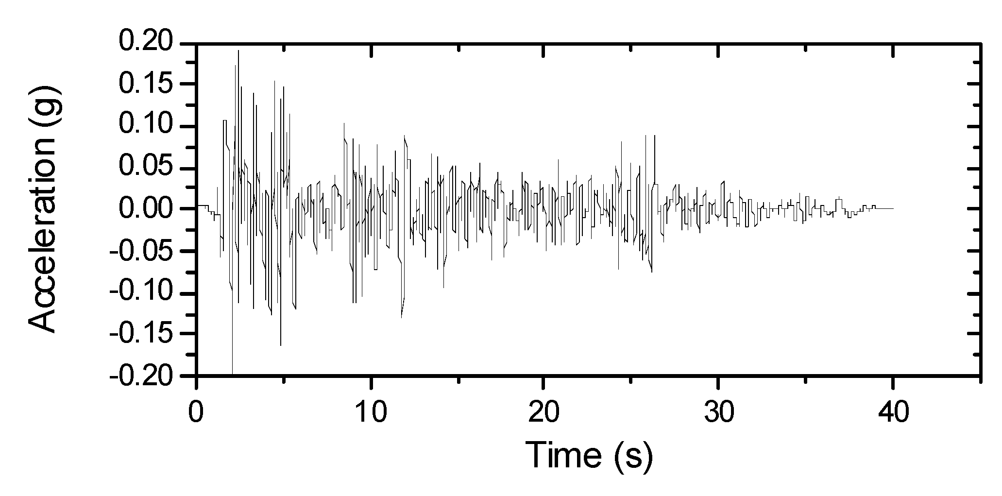
In this section, El Centro seismic wave was selected as the seismic excitation of the structure, and the seismic peak value was adjusted to 0.2 g (Figure 3). In the vibration control analysis on seismic response of PC continuous girder bridge with CSWs, the ground motion input only considered the input along the bridge direction. Under the seismic action with a peak value 0.2 g, the seismic response of PC continuous girder bridge with CSWs may enter an elastic–plastic state. In this paper, the elastic–plastic semi-active control of the bridge structure is not considered, so it is assumed that the structure is in an elastic state under the seismic action. Based on this assumption, the shock-absorbing effect of semi-active control on the seismic response of the composite bridge with CSWS was studied.

6. Establishment of Semi-Active Control System

6.1. Determination of Weight Matrix Coefficient

In the LQR algorithm, the power matrices Q and R are two important control parameters, and the control force and vibration absorption effect of the structure are determined by the selection of Q and R. From the literature [31], it is known that the vibration absorption effect of the structure is only related to the ratio of α and β. Therefore, the values of α and β are determined by conducting parameter analysis in this section. Through preliminary trial calculations, β is firstly determined as 10−5, and the value of α is set to vary from 0 to 100, and a program was written using MATLAB to study the active optimal vibration absorption effect of PC continuous girder bridge with CSWs.
To determine the vibration absorption effect of the PC continuous girder bridge with CSWs, the parameters of vibration absorption effect of the structure are defined as follows:
{ X max i = x n i max x c i max x n i max X r m s i = x n i r m s x c i r m s x n i r m s
{ M max i = M n i max M c i max M n i max M r m s i = M n i r m s M c i r m s M n i r m s
{ F max i = F n i max F c i max F n i max F r m s i = F n i r m s F c i r m s F n i r m s
where X max i   and   X r m s i are the vibration absorption effect of the peak displacement and root mean square displacement of each node of the controlled structure, respectively, and M max i , M r m s i , F max i ,   and F r m s i are the vibration absorption effect of the peak bending moment, peak shear force, and the root mean square values of each node of the structure, respectively. x n i max and x c i max denote the peak displacement response at each node of the structure without and with control, respectively. x n i max and x c i max denote the root mean square displacement at each node of the structure without and with control, respectively. M n i max and M c i max denote the peak moment response at each node of the structure without and with control, respectively. M n i r m s and M c i r m s denote the root mean square moment at each node of the structure without and with control, respectively. F n i max   and F c i max   denote the peak shear response at each node of the structure without and with control, respectively. F n i r m s   and F c i r m s   denote the root mean square shear at each node of the structure without and with control, respectively.
In this section, the peak and the root mean square (RMS) values of the displacement of the midspan node, the bottom bending moment and shear force of pier #2 (fixed pier), and their corresponding vibration absorption effects were selected as research objects to analyze the variation law of each selected vibration absorption effect parameters with the change of the weight matrix coefficient α and to be used as the criteria for determining the value of α.
It can be seen from Figure 4a that the peak displacement and root mean square value response of PC continuous girder bridge with CSWs show a decreasing trend with the increase in α and show a faster change at the beginning, gradually tending to level off when the value of α is 40, and the change curve of root mean square value is more obvious under the seismic excitation. The vibration absorption effect shows an increasing trend with the increase in α, and as the value of α exceeds 40, it gradually tends to be stable. For the changes of bending moment and shear force at the bottom of pier #2, the vibration absorption effect initially shows a faster improving with the increase of α, but gradually tends to level off after α is 40 (as shown in Figure 4b,c). The changes of main beam displacement have a more consistent trend with the internal force changes of pier #2 (as shown in Figure 4d). It can be seen from Figure 4e that the active control force at piers #2 and #3 shows an increasing trend with the increase in α, and the active control force at pier #2 has a larger growth rate. Considering control performance and economy of the control cost, the value of the power coefficient α is determined as 40.
After determining the coefficient α of the weight matrix, the value of the active optimal control force can also be determined. The peak value changing of the optimal control force is analyzed when the value of α is 40 and 100 in Table 1. In the table, Fc_2# and Fc_3# represent the peak active control force of pier #2 and pier #3, respectively, and γ is the growth rate caused by the change in the weight coefficient α.
As is seen in Table 1, when the value of the weight coefficient α is increased from 40 to 100, the increasing of each control index is basically between 3% and 6%, while the active control forces of pier #2 and pier #3 have a larger increase, which indicates that after the value of the weight coefficient α exceeds 40, with the increase in its value, more input is required in the control and the corresponding increase in vibration absorption effect cannot be obtained. Therefore, it is determined that when the weight coefficient α is 40, the active optimal control force of composite bridge control system can be calculated.

6.2. Design Parameters of the Semi-Active Control System

Once the power matrix coefficient is determined through the analysis in the previous section, the active optimal control force can be determined through the active optimal control algorithm LQR and the design parameters of the MR damper can be determined according to the following method.
Assuming that the maximum damping force of the MR damper is equal to the active optimal control force at the corresponding active control position of the bridge and further assuming that the structural vibration absorption effect of the MR damper of the bridge structure is the same as the active optimal vibration absorption effect, then we have
u i s m a x = c i d | x ˙ i s | u i s m a x | + f i d y m a x = c i d | x ˙ i | u i m a x | + f i d y m a x = u i m a x
where i is the position of the MR damper;   u i s m a x and u i m a x denote the maximum control force of the ith MR damper and the active optimal control device, respectively. x ˙ i s | u i s m a x and x ˙ i | u i m a x denote the relative velocities of the maximum semi-active control force and maximum active control force, respectively, in the position of ith MR damper and the active control device.
Assuming that the minimum Coulomb force f i d y m i n of the MR damper is 0 and the adjustable coefficient s is 8, it follows from Equation (15) that
u i s m a x = s c i d | x ˙ i s | u i s m a x | = s c i d | x ˙ i | u i m a x | = u i m a x
Then, the passive viscous damping coefficient of the ith damper can be calculated as
c i d = | u i m a x ( s x ˙ i | u i m a x ) |
The maximum Coulomb force of the ith damper is calculated as
f i d y m a x = ( s 1 )   c i d | x ˙ i s | u i s m a x |
Through the design method of MR dampers mentioned above and the calculation results of active optimal control, the parameters related to the semi-active control system were designed. The design parameter values are shown in Table 2.
Based on the calculation results in Table 2, the MR damper passive viscous damping coefficients for the PC continuous girder bridge with CSWs were finally set at 81,410 N·s/m, 124,839 N·s/m, 81,307 N·s/m, and 81,263 N·s/m, respectively and the maximum Coulomb forces of the dampers were set at 221,620 N, 783 N, 221,795 N, and 221,848 N, respectively. It can be seen from the data that the maximum Coulomb force of the MR damper design is smaller than that of similar semi-active control system of a concrete bridge [32] due to the lighter dead weight of the PC continuous girder bridge with CSWs and the lower axial stiffness, which reduces the design cost and is more economical.

7. Analysis of Semi-Active Vibration Absorption Effect

7.1. Analysis of MR Damper Energy Dissipation

In the event of an earthquake, the energy transferred to the structure from earthquake motion has a significant relationship with damage to the structure. The semi-active control system reduces the seismic response of the structure by increasing the energy dissipation due to the setting of the dampers. This section analyzes the magnitude of the energy consumed by various semi-active control algorithms under the action of earthquake motion from the view of energy and compares it to the energy consumption of the active control. The time–history curves of the energy dissipated by the dampers for each control algorithm are shown in Figure 5, and the total energy dissipated by the dampers of the PC continuous girder bridge with CSWs under various algorithms are given in Table 3.
Figure 5 and Table 3 show that the energy dissipation of the composite bridge structure under various semi-active control algorithms is mainly concentrated in the first 15 s under the same earthquake motion. The energy consumed by each algorithm is different with different control algorithms; Semictrl2 consumes the most significant power, Semictrl1 is the second, and Semictrl3 is the most minor. Further, due to the energy consumption being more significant, the acceleration of the main beam under the action of Semictrl2 is amplified compared to the uncontrolled state. By comparing the energy consumption time–history of the damper under three different semi-active algorithms to the active control algorithm, it is found that the energy dissipation time–history curve of the Hrovat algorithm is closest to that of the active control algorithm, which shows that the Hrovat algorithm has a better vibration absorption effect than the other two semi-active control algorithms in this composite bridge structure.

7.2. Analysis of Peak Vibration Absorption Effect

In order to analyze the vibration absorption effect of PC continuous girder bridge with CSWs by various semi-active control algorithms under the action of earthquake motion, the peak and RMS values of the following parameters of PC continuous girder bridge with CSWs are selected in this section and the vibration absorption effect is analyzed. The parameters, main girder (expressed as mid-span node) displacement, acceleration, and bending moment and shear force at the bottom of pier #2 and pier #3, are respectively represented as Disp-beam, Acce-beam, Move-2#, Shear-2#, Move-3#, and Shear-3#, respectively. The vibration rate absorption of each algorithm is represented by VBR (VBR represents vibration rate absorption). The vibration absorption effect data under various semi-active control algorithms are shown in Table 4.
As can be seen from Table 4, it should be mentioned that the peak seismic response of the PC continuous girder bridge with CSWs is better controlled under the action of different semi-active control algorithms, with the vibration rate absorption ranging from 30% to 60%. The vibration absorption effects on seismic response of different semi-active control algorithms are different; under the action of Semictrl1, the bottom internal force of pier #3 is better controlled, while under the action of Semictrl2 and Semictrl3, the displacement of the main beam and the bottom internal force of pier #2 are better controlled. However, not all the seismic responses of the PC continuous girder bridge with CSWs are controlled under the semi-active control. The semi-active control system of the composite bridge structure is subjected to external energy input, and in order to ensure the overall system energy balance, the semi-active control system amplifies some response parameters while reducing most of the response parameters of the composite bridge structure, such as acceleration, which is amplified under the first two semi-active control algorithms. For this amplification, verification of the design of the semi-active control system is recommended to ensure that the amplified response is tolerable. It is known that the amplified amount is still very small compared to other reduced amount degrees. In comparison to the seismic response of the PC continuous girder bridge with CSWs under the action of three semi-active control algorithms, the seismic response of Semictrl3 algorithm is the closest to the seismic response under active control.
The RMS values of the seismic response of the PC continuous girder bridge with CSWs are better controlled under the action of different semi-active control algorithms, as shown in Table 4. This is different from peak seismic response; the vibration absorption effect on RMS values of the PC continuous girder bridge with CSWs is found to be consistent with the three different semi-active control algorithms. The vibration absorption effects on the displacement of the main girder and the internal force at the bottom of pier #2 are better than the vibration absorption effect on the internal force at pier #3. The RMS values of the seismic response of the PC continuous girder bridge with CSWs under Semictrl3 are better controlled, and the vibration absorption effect is closest to the active control.

8. Analysis of Structural Vibration Absorption Effect

8.1. Time History Analysis of Main Beam Control

In this section, the PC continuous girder bridge with CSWs was excited by El Centro waves, the changes in displacement and acceleration time–history curves of main girder in uncontrolled state and semi-active control state were studied, and the vibration absorption effect of semi-active system of composite girder bridge was analyzed. The displacement and acceleration of the main girder are expressed as mid-span node, and the analysis results are shown in Figure 6.
It can be seen from Figure 6 that the vibration absorption effect of the displacement time history of the PC continuous girder bridge with CSWs subjected to semi-active control under the action of El Centro wave is more obvious—the average vibration rate absorption is 71%—while the vibration absorption effect of the acceleration time history is relatively weaker. Although the vibration absorption effect of peak acceleration is −2% (Table 4), a few time points of the acceleration values under semi-active control exceed the values of uncontrolled state, and most of the time, the acceleration response presents a positive shock absorbing state, which is also indicated by its average vibration rate absorption of 20%.

8.2. Time History Analysis of Pier Internal Force Control

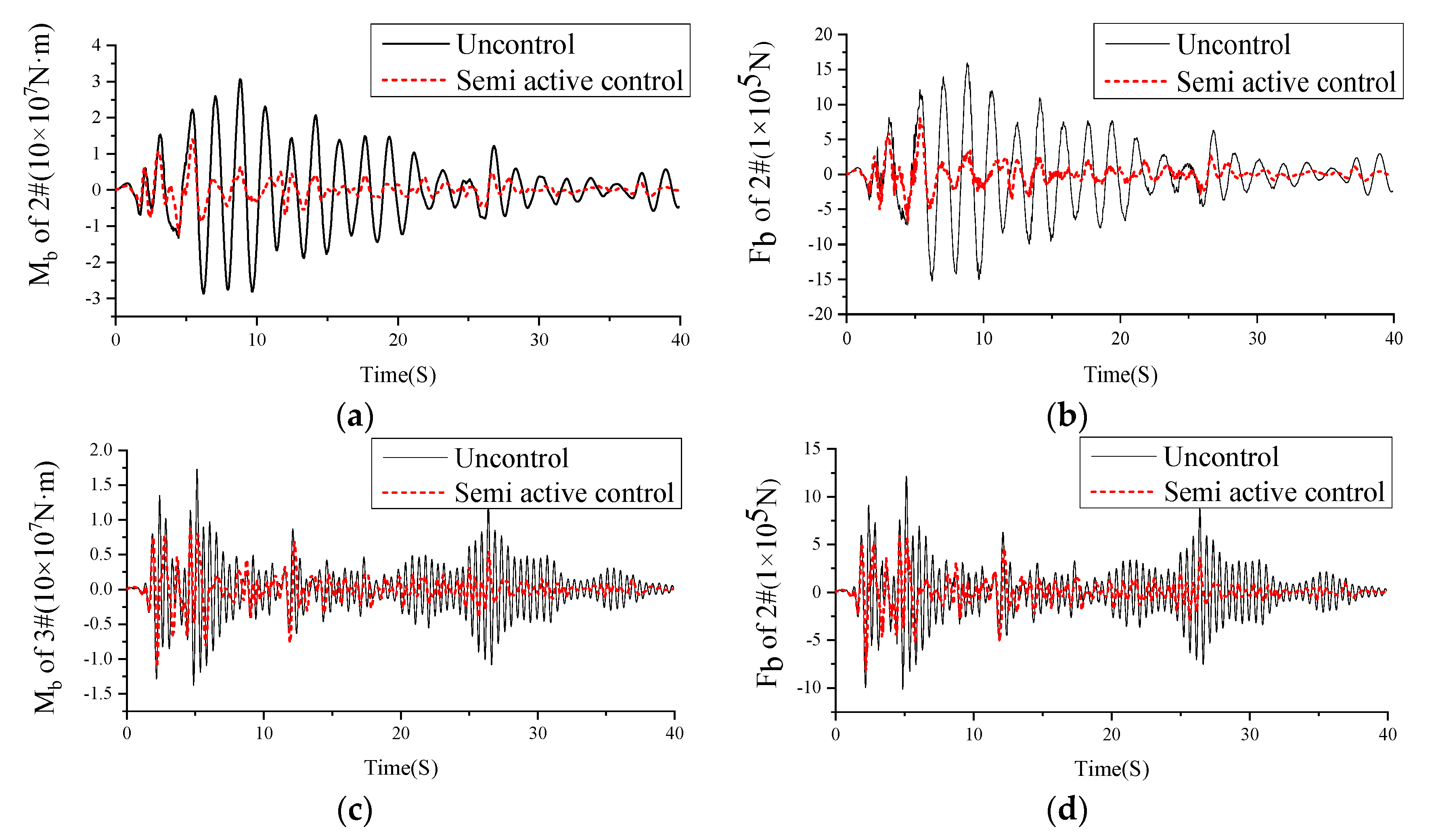
In this section, the influence of semi-active control on the internal force (moment and shear) time–history response of pier #2 and pier #3 of PC continuous girder bridge with CSWs under El Centro wave seismic response was studied.
Figure 7 shows that the bottom bending moment and shear time history curves of piers #2 and #3 have similar curve patterns under uncontrolled and semi-active control conditions. Under the action of El Centro waves, the time history curves of moment and shear at the bottom of pier #2 are similar, and the average vibration rate absorption of bending moment and shear throughout the time history is 70%. From the time history curves of internal force of pier #3, it should be noted that the semi-active control system has a better vibration absorption effect on the internal force at the bottom of piers under the action of El Centro waves, and the average vibration rate absorption throughout the time history is between 42% and 48%.

9. Conclusions

Based on the semi-active control theory, this paper designs a semi-active control system for a three-span PC continuous girder bridge with CSWs, a semi-active control system program of the composite structure is written using MATLAB to study its damping performance, and the following conclusions are obtained.
The parameters of vibration absorption effect of active control system of PC continuous girder bridge with CSWs are studied, and the weight matrix coefficient α is reasonably determined. The use of this coefficient gives the composite girder bridge active control system better vibration absorption effect and economy.
The semi-active control system of PC continuous girder bridge with CSWs is established, and its vibration absorption effect is studied. The results show that the dampers’ energy consumption in the semi-active control system of the composite bridge is the minimum under the semi-active control algorithm of boundary Hrovat. In terms of peak vibration absorption effect of structure, the vibration absorption effect of the semi-active control algorithm of boundary Hrovat is closest to that of an active control algorithm, and the semi-active control algorithm of boundary Hrovat can effectively control the structural vibration response of the PC continuous girder bridge with CSWs.
Under the action of El Centro waves, the semi-active control system of the PC continuous girder bridge with CSWs can effectively reduce the structural response of composite girder. The research shows that the average vibration rate absorption of the girder displacement is 71%, while the average vibration reduction rate of the girder acceleration is 20%.
Under the action of El Centro waves, the semi-active control system of PC continuous girder bridge with CSWs can effectively reduce the structural response of internal forces at the bottom of composite girder piers. The results show that the average vibration rate absorption of bending moment and shear force at the bottom of pier #2 is 70%, while that of pier #3 is between 42% and 48%.
The establishment of a semi-active control system for PC continuous girder bridges with CSWs and the study of its seismic control performance provide some reference for the design of seismic isolation for the composite structure bridge with CSWs. In this paper, only El Centro wave excitation is used to study the vibration absorption performance of the semi-active control system of PC continuous beam bridge with CSWs. Next, the vibration absorption performance of the semi-active control system of the composite bridge with CSWs under seismic wave excitation with different spectral characteristics will be studied. Moreover, the nonlinear response of the composite bridge under seismic action will be further considered to further verify the applicability of semi-active control system of PC continuous girder bridge with CSWs to vibration absorption effect.

Author Contributions

Conceptualization, S.Z. and M.Z.; data curation, Q.S.; formal analysis, C.G.; funding acquisition, S.Z. and M.Z.; software, H.Z.; validation, Q.S. and H.C.; writing—original draft, M.Z.; writing—review and editing, C.G. and H.C. All authors have read and agreed to the published version of the manuscript.

Funding

This research was funded by the National Natural Science Foundation of China, grants No. 52068025 and No. 51968024, and partially by the Project of Post-graduate Innovation Fund of Jiangxi Province, grant number No. YC2021-S438.

Institutional Review Board Statement

Not applicable for this in vitro study.

Informed Consent Statement

Not applicable.

Data Availability Statement

Data available on request from the authors.

Acknowledgments

The author(s) disclosed receipt of the following financial support for the research, authorship, and/or publication of this article: The work described in this article was supported partially by two grants from the National Natural Science Foundation of China (Grant No. 52068025 and Grant No. 51968024) and partially by the Project of Post-graduate Innovation Fund of Jiangxi Province (Grant No. YC2021-S438).

Conflicts of Interest

The authors declare no conflict of interest.

References

  1. Jiang, R.J.; Kwong, A.F.; Xiao, Y.F. Prestressed concrete girder bridges with corrugated steel webs: Review. J. Struct. Eng. 2015, 141, 04014108. [Google Scholar] [CrossRef]
  2. Mo, Y.L.; Jeng, C.H.; Krawinkler, H. Experimental and analytical studies of innovative prestressed concrete box-girder bridges. Mater. Struct. 2003, 36, 99–107. [Google Scholar] [CrossRef]
  3. El, M.A.; Loov, R.E. Corrugated steel webs for prestressed concrete girders. Mater. Struct. 2003, 36, 127–134. [Google Scholar]
  4. Zhou, M.; Yang, D.; Zhang, J.D.; Lin, A. Stress analysis of linear elastic non-prismatic beams with corrugated steel webs. Thin Wall Struct. 2017, 119, 653–661. [Google Scholar] [CrossRef]
  5. Nie, J.G.; Zhu, L.; Tao, M.X.; Tang, L. Shear strength of trapezoidal corrugated steel webs. J. Constr. Steel Res. 2013, 85, 105–115. [Google Scholar] [CrossRef]
  6. Hassanein, M.F.; Kharoob, O.F. Shear buckling behavior of tapered bridge girders with steel corrugated webs. Eng. Struct. 2014, 74, 157–169. [Google Scholar] [CrossRef]
  7. Chen, Y.; Dong, J.; Xu, T. The shear-lag effect of composite box girder bridges with corrugated steel webs and trusses. Eng. Struct. 2019, 181, 617–628. [Google Scholar] [CrossRef]
  8. Mo, Y.L.; Fan, Y.L. Torsional design of hybrid concrete box girders. J. Bridge Eng. 2006, 11, 329–339. [Google Scholar] [CrossRef]
  9. Ding, Y.; Jiang, K.B.; Liu, Y.W. Nonlinear analysis for PC box-girder with corrugated steel webs under pure torsion. Thin Wall Struct. 2012, 51, 167–173. [Google Scholar] [CrossRef]
  10. Shen, K.; Wan, S.; Mo, Y.L.; Li, X.Y.; Song, A.M. A softened membrane model for composite box-girders with corrugated steel webs under pure torsion. Eng. Struct. 2018, 173, 357–371. [Google Scholar] [CrossRef]
  11. Cao, L.; Liu, J.; Chen, Y.F. Theoretical and numerical study on the natural frequencies of bridges with corrugated steel webs. Structures 2018, 15, 224–231. [Google Scholar] [CrossRef]
  12. Ji, W.; Deng, L.; Liu, S.Z.; Lin, P.Z. Study of vertical bending vibration behavior of continuous prestressed concrete box girders with corrugated steel webs. Adv. Struct. Eng. 2016, 19, 953–965. [Google Scholar] [CrossRef]
  13. Moon, J.; Ko, H.J.; Sung, I.H.; Lee, H.E. Natural frequency of a composite girder with corrugated steel web. Steel Compos. Struct. 2015, 18, 255–271. [Google Scholar] [CrossRef] [Green Version]
  14. Zheng, S.M.; Wan, S.; Cheng, H.G. Research on the dynamic characteristics of multi-room single box composite girder with corrugated steel webs. J. Railw. Eng. Soc. 2017, 9, 41–46. (In Chinese) [Google Scholar]
  15. Deng, W.Q.; Liu, D.; Xiong, Y.; Zhang, J. Experimental study on asynchronous construction for composite bridges with corrugated steel webs. J. Constr. Steel Res. 2019, 157, 93–102. [Google Scholar] [CrossRef]
  16. He, J.; Li, X.; Li, C.; Correia, J.; Zhou, M. A novel asynchronous-pouring-construction technology for prestressed concrete box girder bridges with corrugated steel webs. Structures 2020, 27, 1940–1950. [Google Scholar] [CrossRef]
  17. Hung, C.; Lin, G.W.; Syu, H.S.; Chen, C.W.; Yen, H.Y. Analysis of the Aso-Bridge landslide during the 2016 Kumamoto earthquakes in Japan. B Eng. Geol. Environ. 2017, 77, 1439–1449. [Google Scholar] [CrossRef]
  18. Garlock, M. (New York State Department of Transportation, Albany, NY, USA). Private communication. 2008.
  19. Tabar, A.M.; Domenico, D.D.; Dindari, H. Seismic rehabilitation of steel arch bridges using nonlinear viscous dampers: Application to a case study. Pract. Period. Struct. Des. Constr. 2021, 26, 04021012. [Google Scholar] [CrossRef]
  20. Xie, Y.; Zhang, J. Design and optimization of seismic isolation and damping devices for highway bridges based on probabilistic repair cost ratio. J. Struct. Eng. 2018, 144, 04018125. [Google Scholar] [CrossRef]
  21. Jansen, L.M.; Dyke, S.J. Semiactive Control Strategies for MR Dampers: Comparative Study. J. Eng. Mech. 2000, 126, 795–803. [Google Scholar] [CrossRef] [Green Version]
  22. Dyke, S.J.; Jr, B.F.S.; Sain, M.K.; Carlson, J.D. Modeling and control of magnetorheological dampers for seismic response reduction. Smart Mater. Struct. 1996, 5, 565–575. [Google Scholar] [CrossRef]
  23. Sheikh, M.N.; Xiong, J.; Li, W.H. Reduction of seismic pounding effects of base-isolated RC highway bridges using MR damper. Struct. Eng. Mech. 2012, 41, 791–803. [Google Scholar] [CrossRef]
  24. Guo, A.; Li, Z.; Li, H. Experimental and analytical study on pounding reduction of base-isolated highway bridges using MR dampers. Earthq. Eng. Struct. D 2009, 38, 1307–1333. [Google Scholar] [CrossRef]
  25. Sahasrabudhe, S.S.; Nagarajaiah, S. Semi-active control of sliding isolated bridges using MR dampers: An experimental and numerical study. Earthq. Eng. Struct. D 2010, 34, 965–983. [Google Scholar] [CrossRef]
  26. Ok, S.Y.; Kim, D.S.; Park, K.S. Semi-active fuzzy control of cable-stayed bridges using magneto-rheological dampers. Steel Constr. 2007, 29, 776–788. [Google Scholar] [CrossRef]
  27. Lin, W.; Li, Z.; Ding, Y. Trust-region based instantaneous optimal semi-active control of long-span spatially extended structures with MRF-04K damper. Earthq. Eng. Eng. Vib. 2008, 7, 447–464. [Google Scholar] [CrossRef]
  28. El-Khoury, O.; Kim, C.; Shafieezadeh, A.; Hur, J.E.; Heo, G.H. Mitigation of the seismic response of multi-span bridges using MR dampers: Experimental study of a new SMC-based controller. J. Vib. Control. 2016, 24, 83–99. [Google Scholar] [CrossRef]
  29. Heo, G.; Seo, S.; Jeon, S.; Kim, C. Development of a hybrid control algorithm for effective reduction of drift in multispan isolated bridges. Soil Dyn. Earthq. Eng. 2021, 143, 106659. [Google Scholar] [CrossRef]
  30. Omrani, R.; Mobasher, B.; Liang, X.; Gunay, S.; Mosalam, K.M.; Zareian, F.; Taciroglu, E. Guidelines for Nonlinear Seismic Analysis of Ordinary Bridges: Version 2.0; Caltrans Final Report; Caltrans: Sacramento, CA, USA, 2015. [Google Scholar]
  31. Ou, J.P. Structural Vibration Control—Active, Semi-Active and Intelligent Control; Science Press: Beijing, China, 2003. (In Chinese) [Google Scholar]
  32. Qi, X.J. Research on Semi-Active Control of Bridge Damping; Institute of Geophysics, China Seismological Bureau: Beijing, China, 2006. (In Chinese) [Google Scholar]
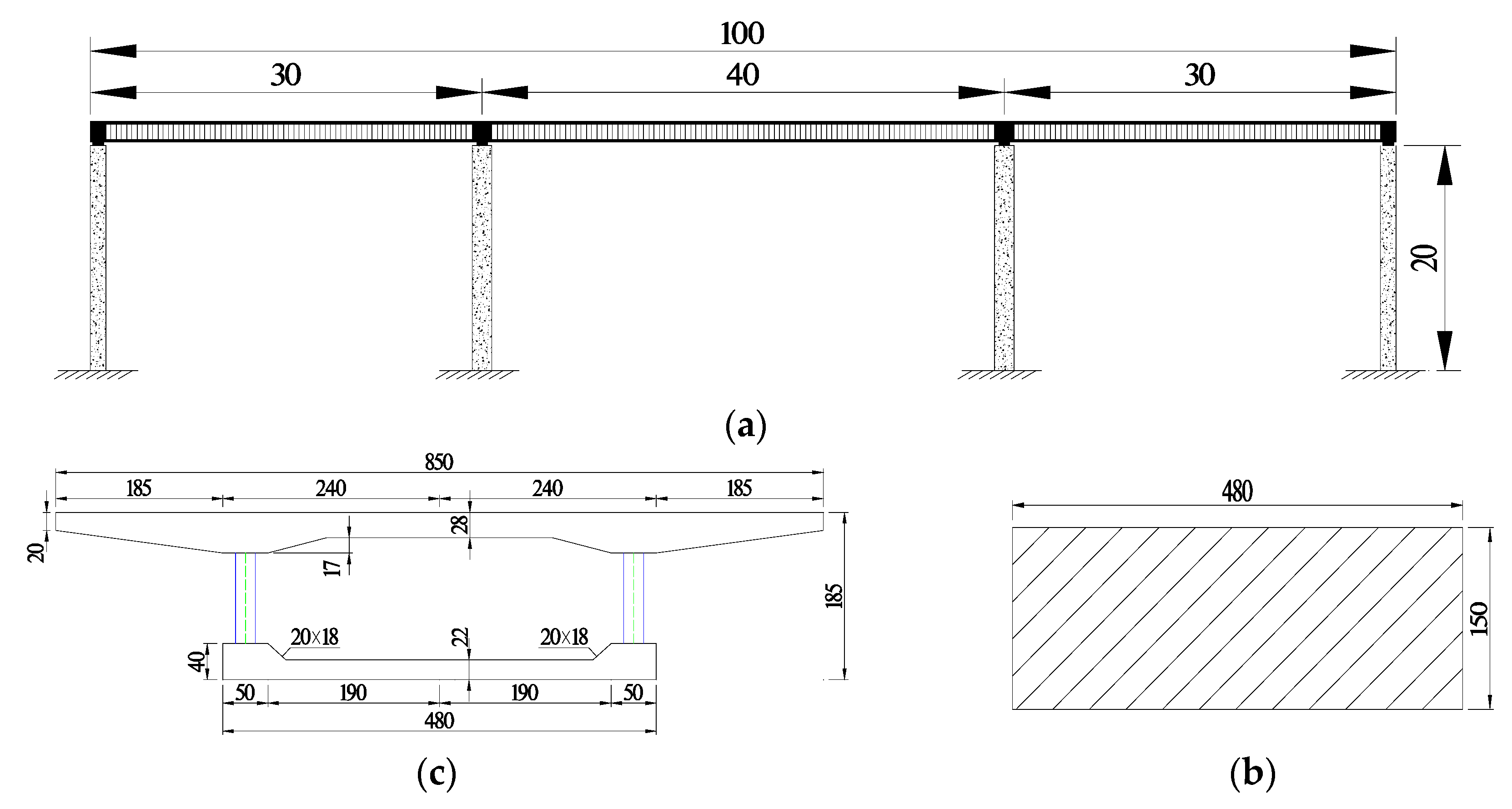
Figure 1. Overall arrangement of the composite bridge: (a) bridge elevation drawing (unit: m); (b) box girder section (unit: cm); (c) pier section (unit: cm).
Applsci 12 12881 g001
Figure 2. Schematic diagram of the finite element model.
Applsci 12 12881 g002
Figure 3. Adjusted El Centro Seismic Wave.
Applsci 12 12881 g003
Figure 4. Response of the composite structure with the weight coefficient: (a) displacement of main beam; (b) bending moment of pier #2; (c) shear of pier #2 bottom; (d) control effect; (e) control force.
Applsci 12 12881 g004
Figure 5. Time–history of energy loss of dampers under various algorithms.
Applsci 12 12881 g005
Figure 6. Time–history curve of the main beam under the action of El Centro seismic wave: (a) displacement; (b) acceleration.
Applsci 12 12881 g006
Figure 7. Time history curve of pier internal force under El Centro seismic wave: (a) #2 pier bottom bending moment time–history curve; (b) #2 pier bottom shear time–history curve; (c) #3 pier bottom bending moment time–history curve; (d) #3 pier bottom shear force time–history curve.
Applsci 12 12881 g007
Table 1. Variation of active optimal control power with weight coefficient.
αXmaxXrmsMmaxMrmsFmaxFrmsFc_2#/NFc_3#/N
400.570.720.570.720.520.72894.69362.53 × 105
1000.600.740.600.740.550.741.92 × 1032.98 × 105
γ5.26%2.78%5.26%2.78%5.77%2.78%114.64%17.65%
Table 2. Parameter design table of MR damper.
Ground MotionEI Centro (PGA = 0.2 g)
Coefficient of Weight Matrixα = 40β = 0.00001
Number of MR damper#1#2#3#4
Active optional control force(N)253,280894.6936253,480253,540
Point in time (s)2.342.232.342.34
Relative velocity (m/s)0.3889−0.00089590.38970.3900
Adjustable multiple of damping force8888
Viscous damping coefficient of MR damper (N·s/m)81,409.10124,838.6481,306.1381,262.82
Maximum Coulomb force of MR variable damper (N)221,620.00782.86221,795.00221,847.50
Minimum Coulomb force of the MR variable damper (N)0000
Table 3. Energy consumption of dampers under the action of various algorithms.
Control AlgorithmSemictrl1Semictrl2Semictrl3Active
Energy consumption
(MJ)
4.399.094.034.07
Note: MJ = 1 × 10⁶ N·m.
Table 4. Analysis of various semi-active vibration absorption effects (peak and RMS).
Seismic ResponseDisp-Beam
(cm)
Acce-Beam
(m/s2)
Move-2#
(1 × 10⁷ N·m)
Shear-2#
(1 × 10⁵ N)
Move-3#
(1 × 10⁷ N·m)
Shear-3#
(1 × 10⁵ N)
UnctrlPeak9.932.303.0715.921.7312.12
RMS3.180.550.985.080.362.55
Semictrl1Peak5.772.841.839.960.815.50
RMS1.340.660.422.230.261.76
VBR1Peak42%−23%40%37%53%55%
RMS58%−20%57%56%28%31%
Semictrl2Peak4.472.991.398.501.217.76
RMS1.240.590.392.060.311.87
VBR2Peak55%−30%55%47%30%36%
RMS61%−7%60%59%14%27%
Semictrl3Peak4.512.351.398.011.128.19
RMS0.930.440.291.500.211.33
VBR3Peak55%−2%55%50%35%32%
RMS71%20%70%70%42%48%
ActivePeak4.292.371.327.611.207.99
RMS0.880.430.271.430.211.37
VBR4Peak57%−3%57%52%31%34%
RMS72%22%72%72%42%46%
Publisher’s Note: MDPI stays neutral with regard to jurisdictional claims in published maps and institutional affiliations.