Article

Evaluation of Criteria for Out-of-Plane Stability of Steel Arch Bridges in Major Design Codes by FE Analysis

1
College of Civil Engineering, Fujian University of Technology, Fuzhou 350118, China
2
Fujian Provincial Key Laboratory of Advanced Technology and Informatization in Civil Engineering, Fujian University of Technology, Fuzhou 350118, China
3
College of Civil Engineering, Fuzhou University, Fuzhou 350118, China
*
Author to whom correspondence should be addressed.
Appl. Sci. 2022, 12(24), 12632; https://doi.org/10.3390/app122412632
Submission received: 30 October 2022 / Revised: 1 December 2022 / Accepted: 4 December 2022 / Published: 9 December 2022
(This article belongs to the Topic Advances on Structural Engineering, 2nd Volume)

Abstract

:
The provisions for out-of-plane stability of steel arch bridges in three major design codes are presented in this paper. By employing an existing steel arch bridge as a model, the influence of bridge type, arch rib to lateral bracing stiffness ratio, rise-to-span ratio, arch rib spacing, and range of lateral bracing arrangements on the out-of-plane critical axial force of the arch rib is studied using FE analysis. The accuracy of the critical axial force provisions is then evaluated against the FE analysis. The results show that the influence of the rise-to-span ratio on critical axial force is generally small. The critical axial force decreases with increasing arch rib spacing when the stiffness ratio is relatively large. A smaller ratio of arch rib length provided with lateral bracing (γ-value) significantly reduces the critical axial force and normalized critical axial force decreases with increasing stiffness ratio. The critical axial force of half-through type arch bridges is lowest when the stiffness ratio is relatively small. A deck-type bridge has a larger critical axial force than a through-type bridge when the stiffness ratio is relatively large, while the results are the opposite when the ratio is small. The different assumptions made in the provisions result in the various parameters having different impacts on the out-of-plane critical axial force in each code, thus affecting code accuracy. Considering the influence of the rise-to-span ratio, ratio of lateral bracing, and arch rib spacing with different stiffness ratios, factors to improve the accuracy of the critical axial force obtained by the three codes are proposed for a practical design process.

1. Introduction

A steel arch rib is a structure curved in the elevation plane. Its main load-carrying mechanism is compression and bending. Once a certain critical level of force acts on the arch rib, the joint action of torsion and transverse bending will deform the member and make it break away from its original plane, as shown in Figure 1. This critical load has a close connection with the distribution and characteristics of the load, the geometric diversity of the arch axis, variations in the flexural and torsional stiffness of the cross-section along the arch axis, the restraint available at the supports and elsewhere, residual stress resulting from manufacture and fabrication, and yielding of the steel. Due to the diversity and complexity of parameters, in-depth studies are needed for the determination of buckling loads, and the development of accurate and simple codes can be a long process.
Through numerous investigations, our understanding of arch ribs has progressed over time. Studies on practical engineering are no longer a one-sided consideration of a certain factor, the sample idealized theoretical models were abandoned, and more attention is paid to the analysis of the actual structures as a whole system. Moreover, our apprehension of out-of-plane stability has also developed from a single arch to the whole structural system. For circular arches, Timoshenko and Gere [1] used an analytical method to resolve the out-of-plane buckling problem under uniform radial loads and uniform moments. The ultimate uniformly distributed vertical force sustained by an arch fixed against rotation in the transverse direction was expressed by Demuts [2]. Lu [3] presented a theoretical study for the out-of-plane buckling of elastic circular arches under a central radial point load using an energy method and an experimental study for the out-of-plane buckling load of elastic circular aluminum arches under a central radial point load. With regard to parabolic arches, the ultimate out-of-plane uniformly distributed vertical load was proposed by Tokarz and Sandhu [4], with additional information available in papers by other investigators [5,6,7,8]. In the existing arch bridges, almost every arch rib is arranged with transverse bars according to certain rules. The elastic lateral buckling of twin arch ribs braced with transverse bars normal to the plane of the ribs has been studied by several investigators [9,10]. It is found that the nature of the bracing system is of great significance for restraining lateral buckling: the location and spacing of the transverse bars, the distance between the arch ribs, and the flexural stiffness of the bars around the vertical and longitudinal axis. Sakimoto and Komatsu [11] investigated the requirement of diagonal bracing members to make sure the whole arch system is provided with the necessary lateral stability. Kuranishi and Yabuki [12] presented the ultimate strength of braced steel arches under the combined action of vertical and horizontal uniform loads. The out-of-plane elastic buckling behavior of hinged planar truss arch with lateral bracings is obtained theoretically by Guo [13].
Through extensive parametric research, researchers proposed an approximate method to calculate the strength of steel arches which failed due to the out-of-plane instability [14,15]. A procedure to determine the effective buckling length by spatial eigenvalues was suggested [16]. Finite element (FE) analysis results for the elastic–plastic buckling and ultimate strength of steel wide-flange arches were presented [17]. Lim and Kang [18] obtained closed-form solutions for the torsional buckling moment of braced arches in uniform bending and for the torsional buckling load of braced arches in uniform compression. Pi and Bradford [19] studied the out-of-plane elastic and inelastic flexural–torsional buckling behavior, as well as the theoretical calculation method of the strength of fixed steel arches. A method for analyzing the plastic collapse load of circular arches under the influence of vertical loading was developed by Spoorengerg et al. [20]. The stability of a leaning arch structural system was investigated experimentally by Liu [21]. Bouras [22] investigated the flexural–torsional buckling behavior of arches under mechanical and thermal loading. Zhong [23] investigated the out-of-plane dynamic stability of an arch under vertical periodical base excitation by using both analytical and experimental methods.
In a word, the study of the critical load of steel arch bridges has, over time, expanded from linear to nonlinear, from in-plane to spatial, and from arch ribs to whole arch bridges [24]. Over the past few decades, extensive work relating to theory, numerical methods for second-order analysis, and advanced analysis has been conducted. However, the update of standards lags behind the progress in the understanding of arch rib stability. Standards and guidelines on the use of plentiful parameters tend to lack explicit recommendations for different bridge types, and the theoretical education of engineers is also lagging behind. For further development of reliable and effective codes, the next work is imperative to perfect design methods for actual structures that take into account multiple factors of nonlinearities to ensure the safety and economy of actual projects.
In this paper, relevant provisions about the out-of-plane stability of steel arch bridges in major codes are summarized, including the Chinese code, Fundamental Code for Design on Railway Bridge and Culvert [25], the Japanese code, Specification for Highway Bridge [26], and Eurocode 3: Design of Steel Structures [27]. LRFD Bridge Design Specifications [28] are not included. This code takes steel arch ribs as steel members subjected to combined axial compression and flexure, which means that there is no relative provision to calculate the out-of-plane critical axial force for arch ribs. An arch under a central in-plane load may lose its stability in an out-of-plane buckling mode when the load attends a certain value [29]. The maximum axial force of the arch rib in case of out-of-plane instability of an arch bridge is defined as out-of-plane critical axial forces, Ncr. When calculating the out-of-plane instability bearing capacity of a steel arch bridge, the Chinese code, the Japanese code, and the European code all regard the arch rib as the compressed lattice column, and the axial force when the lattice column is unstable is taken as the critical axial forces of arch rib, however, each specification considers different influencing factors.
In order to analyze the major influencing factors of out-of-plane critical axial forces, finite element analysis is used in this paper. The main structural parameters discussed in this paper include the types of bridges, the range of lateral bracing arrangements, the arch rib spacing, the ratio of stiffness between the arch ribs and the lateral bracing, and the rise-to-span ratio. Then, by using the finite element analysis, the critical axial force for arch ribs given by the codes is normalized and evaluated so as to discuss the accuracy of provisions presented in major design codes. At the end of this paper, improvements to the code calculations are put forward. The results may provide a reference for scholars and engineers to revise the design criteria for steel arch bridges.

2. Outline of Out-of-Plane Stability Provisions in Each Code

2.1. Chinese Code

The Chinese code regards the arch rib as a Vierendeel truss of length equal to the arch axis for approximate checking of out-of-plane stability, as shown in Figure 2, and the truss is under the influence of longitudinal force N on the quarter point of the arch rib. N can be performed using the following equation:
N = H / cos ϕ m
In this equation, H represents the horizontal component of the axial force of the arch rib and φm represents the angle between the quarter point on the arch axis and the horizontal plane. The critical axial force Ncr is calculated by:
N c r = α 0 π 2 E I S 2
S is the length of the arch axis, the symbol E in Equation (2) represents the Young’s modulus of the arch rib, I is the moment of inertia of two chords around the common axis (central longitudinal axis of the bridge) α0 is calculated as follows:
α 0 = 1 1 + π 2 E I S 2 a b 12 E I b + a 26 E I y 1 1 μ
a represents the panel length, b represents the spacing between the arch ribs, Ib represents the moment of inertia of the transverse bracing, and Iy is the out-of-plane moment of inertia of the arch rib. The μ-value can be obtained using Equation (4), and μ-value must be less than 1.
μ = N c r a 2 2 π 2 E I y
During calculation, the μ-value is assumed first, and the Ncr value is calculated according to Equations (2) and (3). Then the Ncr value is substituted into Equation (4) to calculate the μ-value, and the Ncr value is obtained through continuous iterative calculation.
Figure 2. Simplified Calculation Model of Arch Rib: (a) Simplified Model of Arch Rib; (b) Equivalent Vierendeel Truss.
Applsci 12 12632 g002

2.2. Japanese Code

A steel arch bridge can be approximately regarded as a narrow and long-span structure system with a tendency to buckle laterally away from the arch plane, so the Japanese code establishes rules and regulations for verification of out-of-plane buckling. If the arch axis forms a symmetrical parabola in the vertical plane, and if lateral bracing and sway bracing are installed on the basis of provisions presented in Japanese code, the verification of out-of-plane buckling can be performed using the following equation:
H / A g 0.85 σ c a
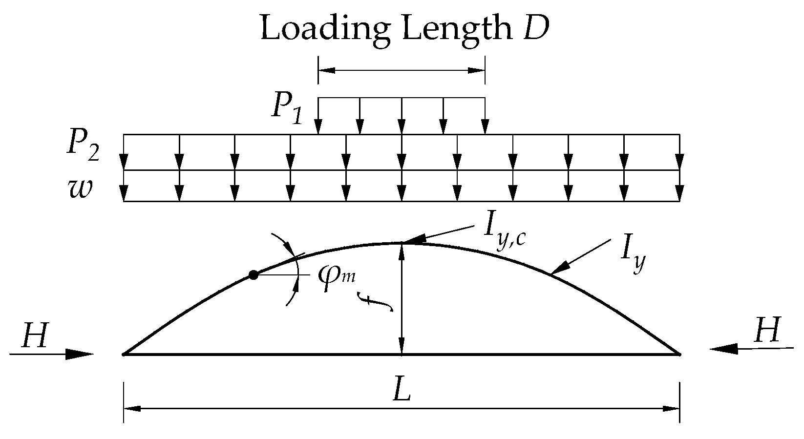
The meaning of symbol H can be seen in Figure 3; it represents the horizontal component of the axial force of the arch rib under load. Ag is the mean value of the gross cross-sectional area of the members of a single arch, σca is the allowable axial compressive stress at the position of 1/4 span of a single arch rib. σca is only relevant to slenderness ratio l/r, and can be calculated according to some equations in tables of specifications when the local bucking of the arch rib is not taken into consideration. In this regard, the calculation method of the radius of rotation and the effective buckling length is shown in Equation (6).
r = I y + A g b 2 2 / A g ,   l = ϕ β z L
In this equation, b is the spacing between the arch ribs, L represents the bridge span, the mean value of the moment of inertia around the vertical axis of the members of a single arch rib is represented by the symbol Iy, and βz takes the values as shown in Table 1. When the value of f/L falls between values given in Table 1, βz may be interpolated in a linear manner. Here, f is the rise of the arch. Values of φ are specified as follows: for a midheight-deck stiffened arch φ = 1, for an upper-deck stiffened arch φ = 1 + 0.45 k, and for a through stiffened arch φ = 1 − 0.35 k. Here, k is the ratio of the load shared by the hangers or shoring to the total load in the loading state shown in Figure 3. While considering the upper-deck stiffened arch, the value of k should be set at 1 if the arch and stiffening girder are not rigidly lined at the arch crow. P1, P2, and w in Figure 3 are the vehicle load, lane load, and dead load acting on the main structure, respectively.
Figure 3. Loading State to be Used for Verifying Out-of-plane Buckling.
Applsci 12 12632 g003

2.3. Eurocode 3

According to Eurocode 3, by inspecting the stability of the end portals, the out-of-plane stability of arches with wind braces and portals can be verified. Equation (7) shows the calculation method of the out-of-plane critical axial force in arches with wind braces and portals.
N c r = π 2 E I ( β h ) 2
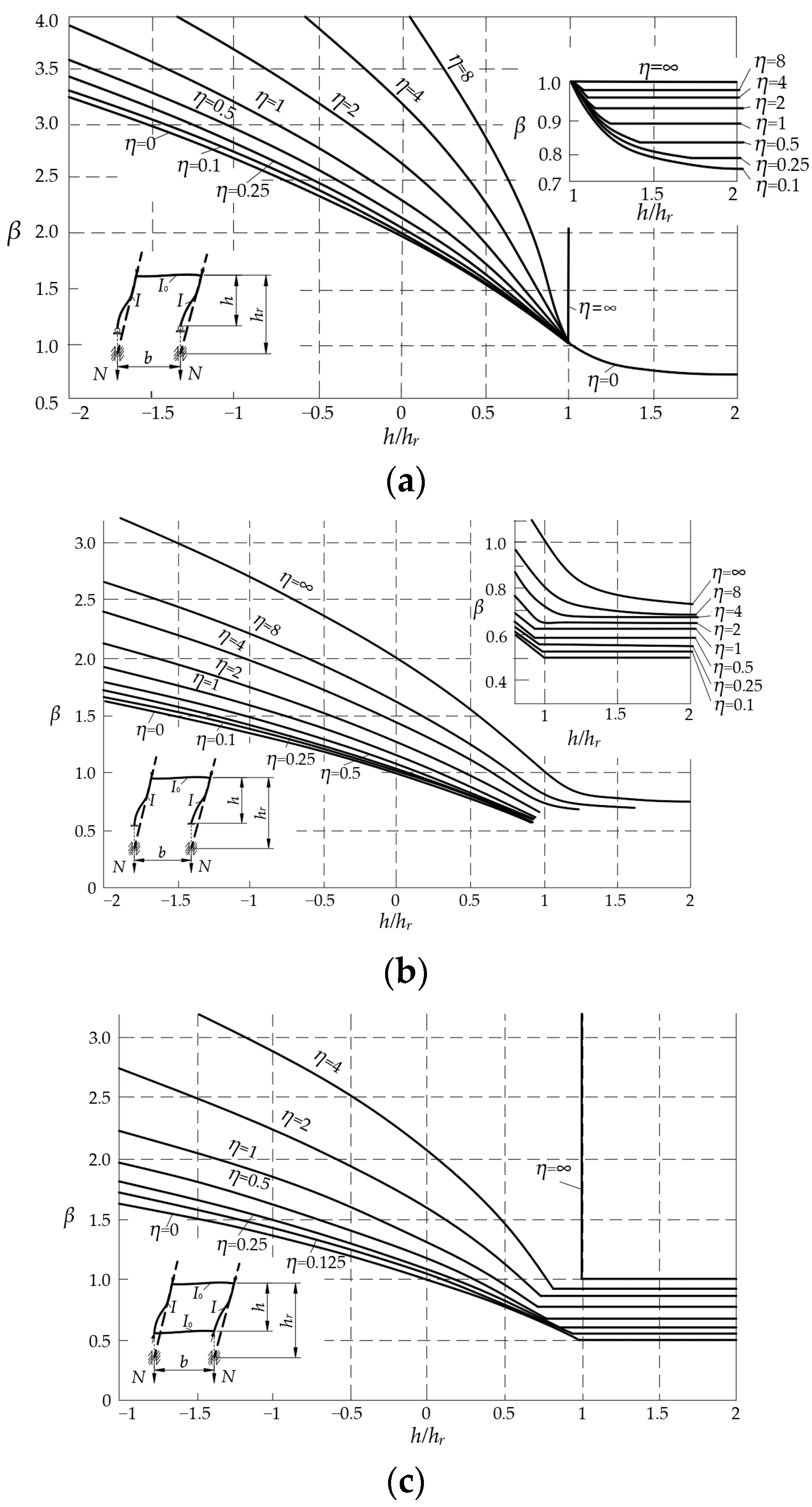
where EI is the out-of-plane flexural stiffness of the arch rib, h is the length of the springing to the first brace as shown in Figure 4, the buckling length factor β can be taken from Figure 5 using the geometry in Figure 4, β-value considering the three different boundary conditions of springing, including arch springing hinged, arch springing fixed, and arch springing with wind brace. The value hr in Figure 4 and Figure 5 can be taken as the mean of all lengths hH/sinαk of the hangers. hH is the length of each hanger, αk is the angle between the arch axis and the horizontal line at the springing. η in Figure 5 is the stiffness ratio between the arch rib and end brace, which can be calculated according to Equation (8), in which b is the arch rib spacing, I0 is the bending moment of inertial of the first transverse brace along the horizontal axis.
η = E I b E 0 I 0 h

3. Bridges Analyzed and Method of FE Analysis

3.1. Bridges Analyzed and Study Parameters

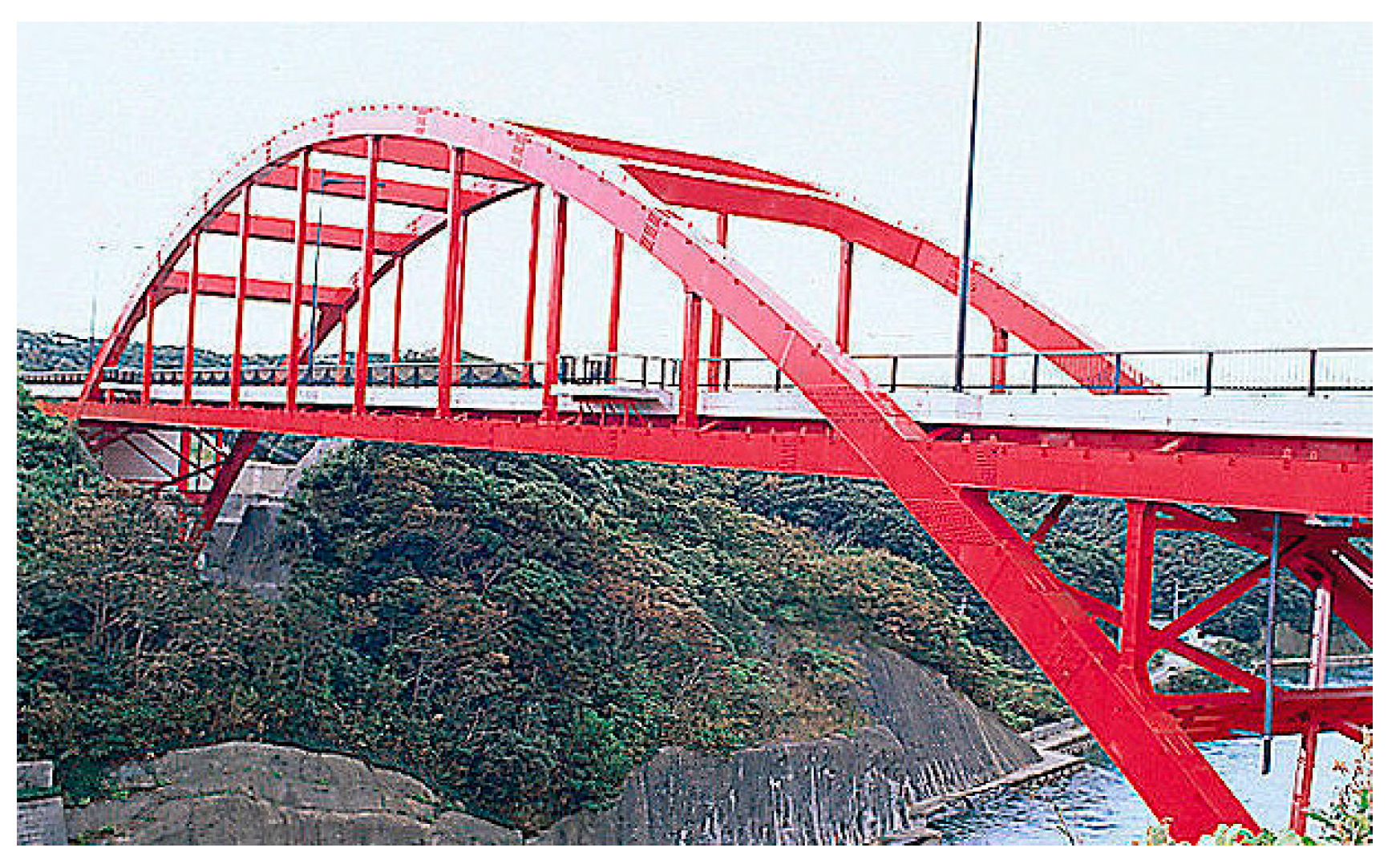
The bridge selected for analysis in this study is the Manzeki Bridge, located in Nagasaki prefecture, Japan. The main span and rise of this half-through type arch bridge are 113 m and 24 m, respectively. Box sections are adopted for arch rib and lateral bracing, and I-sections are adopted for longitudinal and cross girders and hangers. It employs quadratic parabola arch axes (see Figure 6). In order to reveal the differences between provisions in the codes for different bridge types, the girder framework of this bridge is translocated in the models to simulate the other two bridge types (through-type and deck-type) while keeping the other parameters constant.
In the major design codes, the out-of-plane critical axial force of the arch ribs is specified instead of the critical flexure load. Therefore, the out-of-plane stability of a steel arch bridge is studied in this paper by focusing on the critical axial force. Since the influences of stiffness ratio, bridge type, rise-to-span ratio, range of lateral bracing arrangements, and arch rib spacing are concurrently provided in most major design codes, the effect of these parameters on critical axial force according to the various codes is evaluated by FE analysis. The stiffness ratio is the value of out-of-plane flexural stiffness of the arch ribs divided by the flexural stiffness around the horizontal axis of the lateral bracing; this is abbreviated as SR in the figures in the following sections.
To reveal the influence of stiffness ratio on critical axial force, three different arch rib and bracing cross sections are used, as shown in Table 2, and the nine cases shown in Table 3 are studied to discuss the influence of rise-to-span ratio, range of lateral bracing arrangements, and arch rib spacing on critical axial force for each type of arch bridge. These cases will be identified in the form AmBn in the figures in the following sections, where A and B are the abbreviations of the arch rib and bracing, respectively, and m and n are the cross-section types of the arch rib and lateral bracing, respectively. Taking structural aesthetics and reasonable engineering into account, the rise-to-span ratios of the three bridge types modeled here were set between 0.15 and 0.5 by changing the arch rise. The range of lateral bracing arrangements is represented by the γ-value shown in Figure 7, which is the ratio of arch rib length provided with lateral bracing to the longness of arch. This value is set between 0.23 and 0.86. The arch rib spacing was varied between 6 m and 14 m. The rise-to-span ratio, γ-value, and arch rib spacing of the basic model are 0.25, 0.86, and 10 m, respectively. In this study, the values of the other two parameters are kept constant when discussing the influence of one parameter.

3.2. FE Analysis

3.2.1. FE Modeling

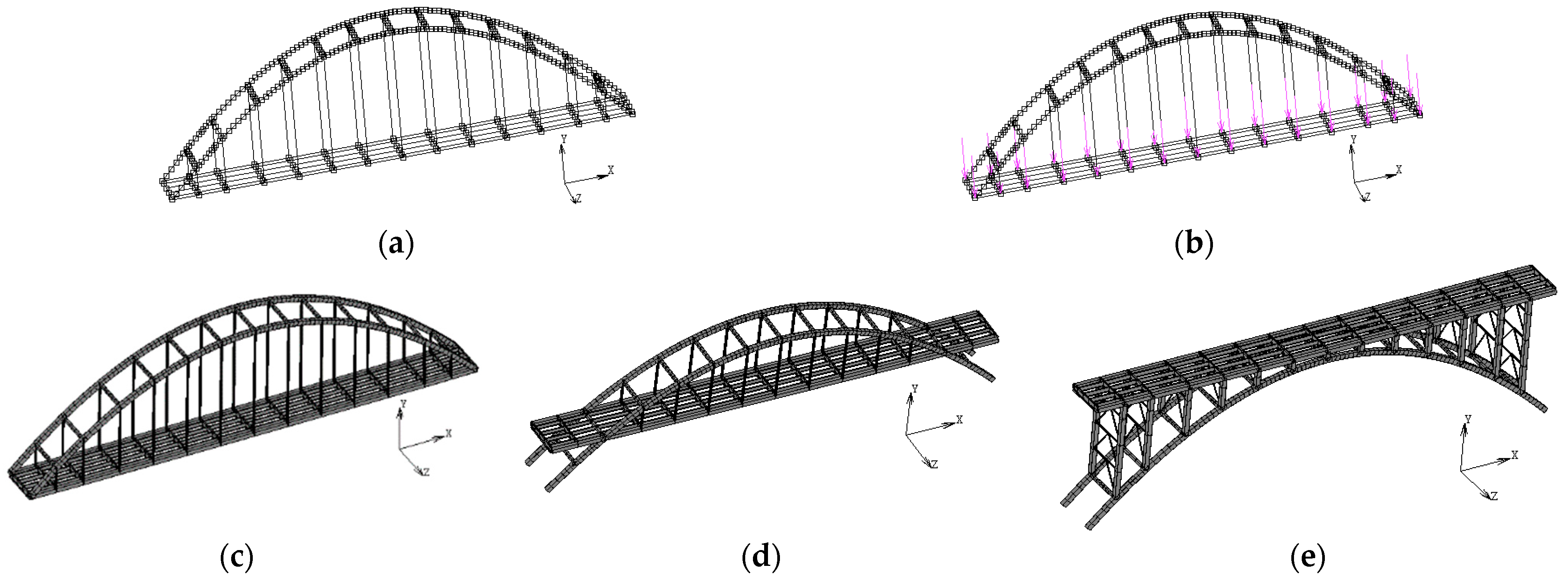
The finite element models were developed using MSC. Marc. The mesh size will affect the accuracy and calculation time of the FE analysis. Since the number of elements and nodes in a single FE model in this paper is not large, after ensuring that nodes are set at special positions such as springing, vault, and intersection point of arch rib and suspender, arch rib and transverse brace are divided by elements with small length and approximately equal length, each element is about 1.2 m long. As the longitudinal beam, cross beam, and suspender are not the focus of this paper, their elements are not subdivided. The nodes and elements of the FE model are divided, as shown in Figure 8a. The beam elements of type 14 and 79 were adopted to develop the members of box sections and I-shaped sections, respectively. The deck of the bridge was ignored. To simplify calculation according to the codes in the following sections, the arch ribs were simplified to have a constant section. An initial out-of-plane deflection of 20 L / 300 in the shape of the first-order out-of-plane buckling mode was assumed. Three degrees of translation freedom at the springing of two arch ribs were fixed. The dead load of the bridge was automatically determined by the software according to the inputted material density and element volume. According to the influence line of springing axial force, the live load was applied as a full-span uniform load, as shown in Figure 8b. The established FE models of through-type, half-through type, and deck-type steel arch bridges are shown in Figure 8c–e.
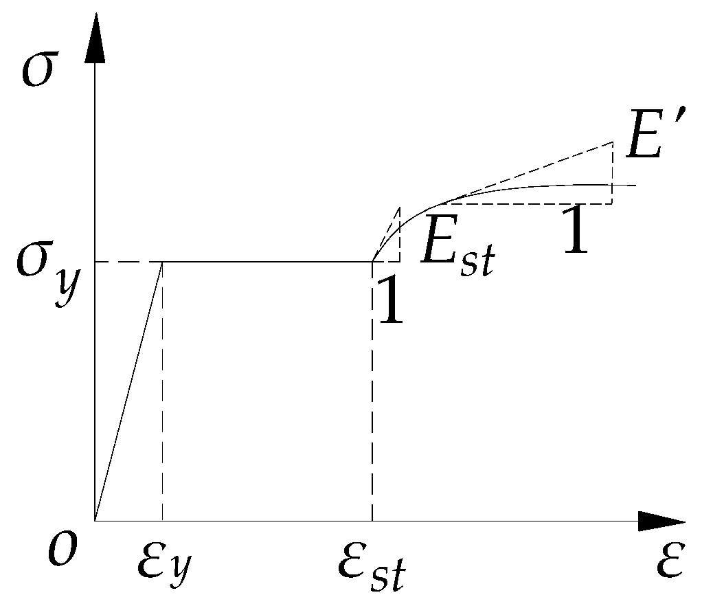
There are two kinds of arch instability: branch point instability and extreme point instability. Extreme point instability often occurs in practical steel arch bridges. To obtain a relatively accurate evaluation of out-of-plane critical axial force, it is advisable to adopt the analytical method considering the material and geometric nonlinearity [13,24]. The nonlinear equilibrium equation was solved by the Newton–Raphson iterative method. Large deformation effects were considered by using the updated Lagrangian formulation to conduct geometrical nonlinear analysis. The nonlinearity of the material is considered in the establishment of the FE model. For the box sections and I-shaped sections, 28 and 24 integration points were specified, respectively. The constitutive relation of steel proposed by Usami et al. [30] was employed, and the stress–strain curve is shown in Figure 9. Here, σy represents the yield stress and the εy is the yield strain, εst and Est represent the strain at the onset of strain hardening and initial strain-hardening modulus, respectively. Equation (9) shows the calculation of strain hardening modulus E′:
E = E s t exp ( ξ ε ε s t ε y )     ( ε s t ε )
where ξ is a material coefficient. Japanese Industrial Standards (JIS) SM490Y steel is assumed in this study, with E = 2.06 × 10⁵ MPa, σy = 355 MPa, Poisson’s Ratio ν = 0.3, εst = 7εy, Est = E/30 and ξ = 0.06.

3.2.2. Accuracy Verification of FE Analysis

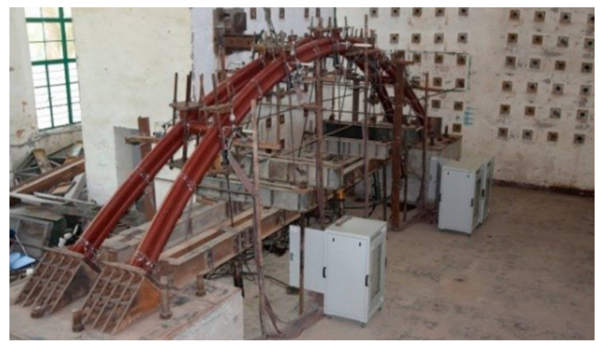
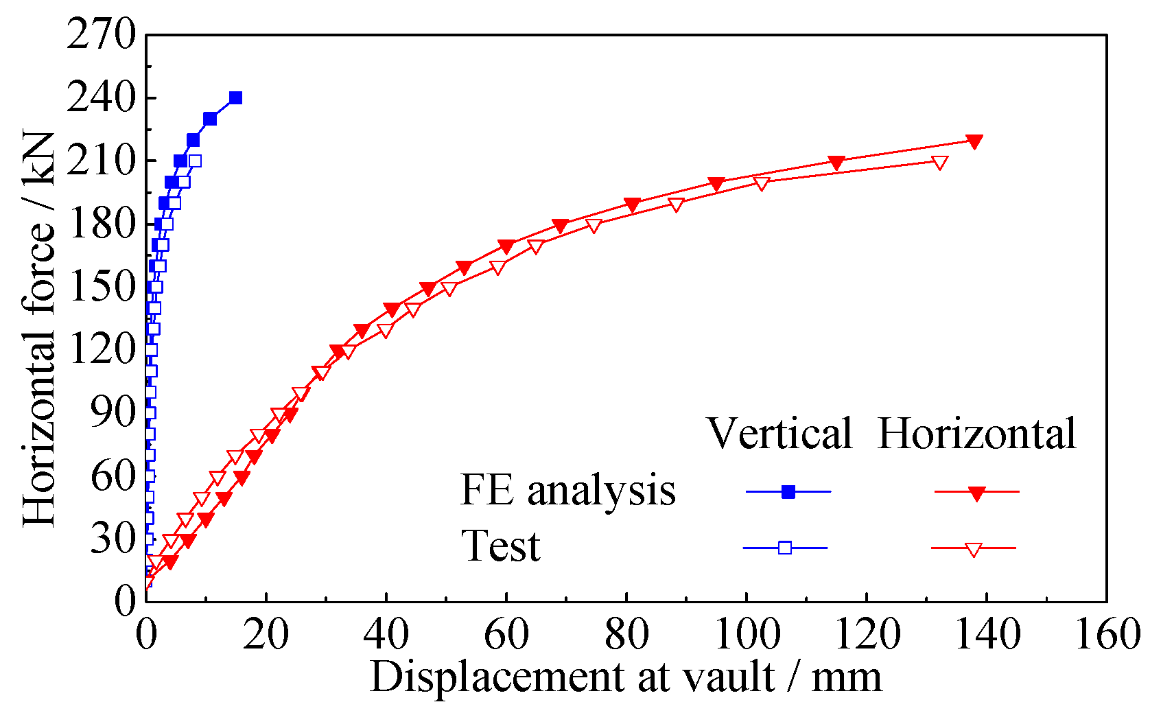
A specimen test conducted by the authors is used to verify the accuracy of the finite element modeling in this paper. The net span of the test specimen is 8.50 m, the rise-to-span ratio is 1/4.5, and the arch axis is a quadratic parabola. The arch rib is a dumbbell shape, and the arch rib is made of Φ108 mm × 4 mm steel tube. The two arch ribs are inward tilted 7.5° to form the basket arch. The spacing of arch ribs at the springing and vault is 0.8 m and 0.29 m, respectively. The steel tubes of Φ152 mm × 4.5 mm are used to connect the two arch ribs at the six equal diversion points of span. The specimen uses steel longitudinal beams to simulate the rigid ties of the original bridge, and the springing is welded to the skewback through triangular steel plates. In this experiment, a horizontal load is applied to the vault of the arch through a jack. The test specimen and its loading photo are shown in Figure 10.
The FE model of the test specimen was established using the modeling method in Section 3.2.1. The comparison between the results of the test and the FE analysis is shown in Figure 11. It can be seen from Figure 11 that the load–lateral displacement curve and load–vertical displacement curve obtained by the test and FE analysis have the same regular and similar values, which verifies the accuracy of the finite element modeling method presented in this paper.

4. Discussion of FE Analysis Results

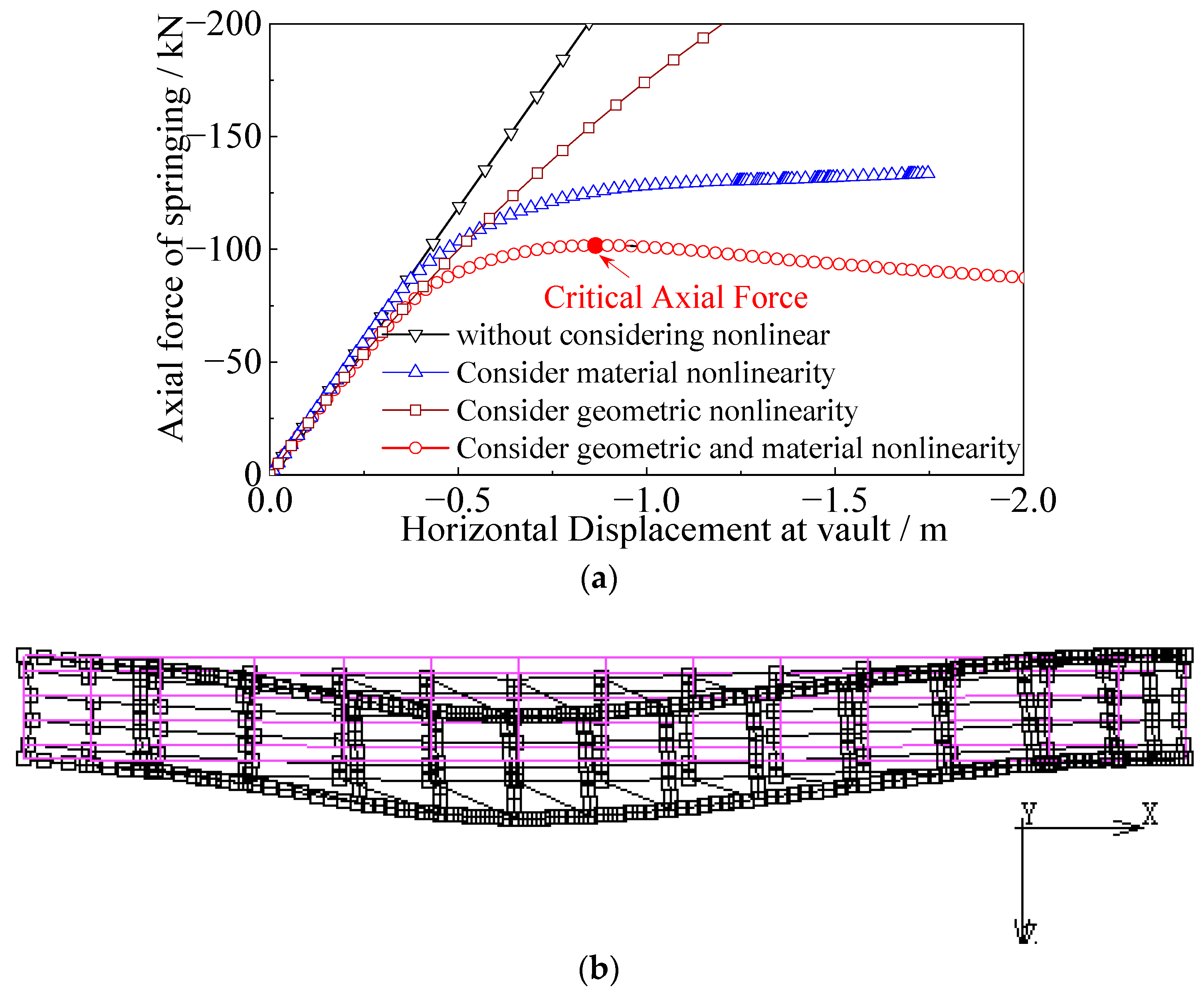
The springing in the arch rib has the largest axial force. Taking the analysis results of a FE model as an example, Figure 12a shows the springing axial force versus vault horizontal displacement curves under four conditions: not considering geometric and material nonlinearity, only considering material nonlinearity, only considering geometric nonlinearity, and simultaneously considering geometric and material nonlinearity. Figure 12a shows that geometric nonlinearity has little influence on the springing axial force of steel arch bridges, while material nonlinearity has a great influence, and both material and geometric nonlinearity should be considered when calculating the out-of-plane stable bearing capacity of steel arch bridges. An arch under a central in-plane load may lose its stability in an out-of-plane buckling mode when the load attends a certain value. When the axial force of springing reaches the maximum value (red dot in Figure 12a), out-of-plane instability of the arch rib occurs, and the mode of out-of-plane instability is symmetrical, as shown in Figure 12b. In FE analysis, the maximum axial force of the arch rib in case of out-of-plane instability of the arch bridge is defined as out-of-plane critical axial forces, Ncr.
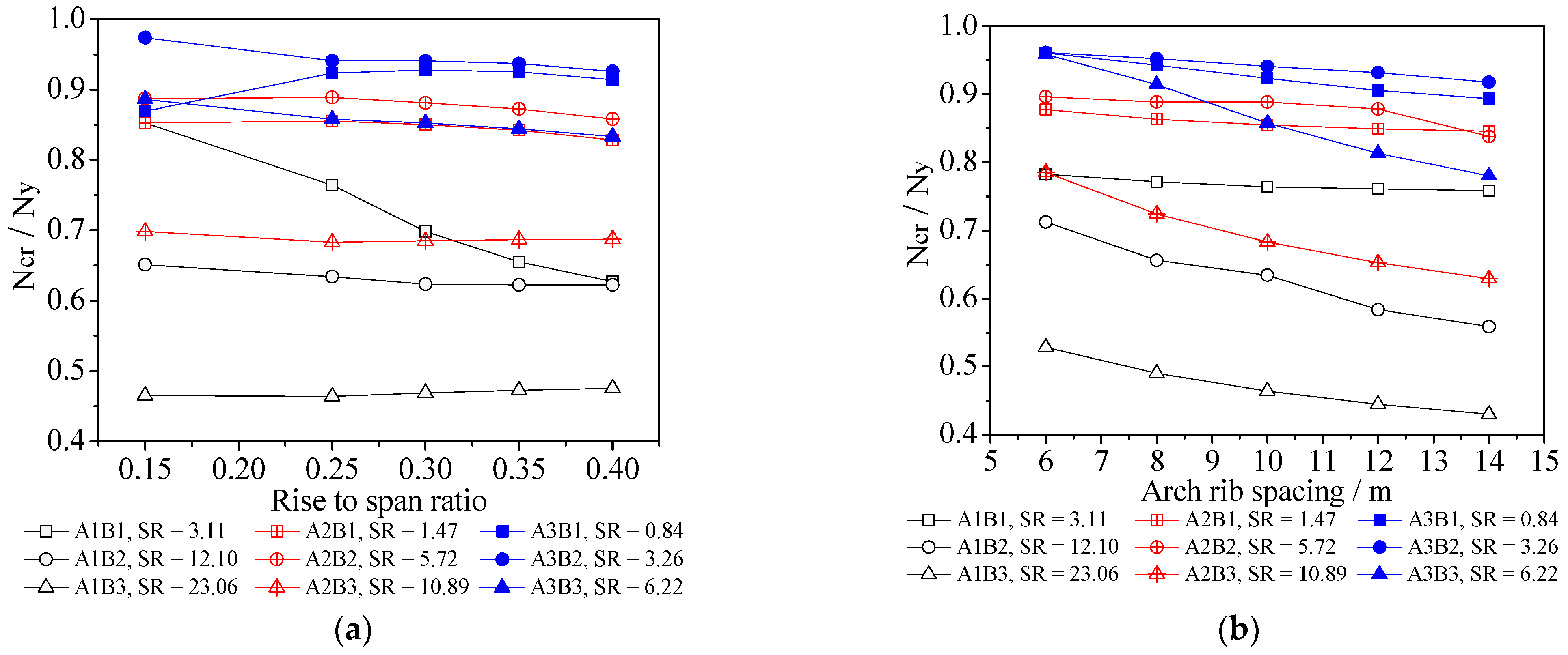
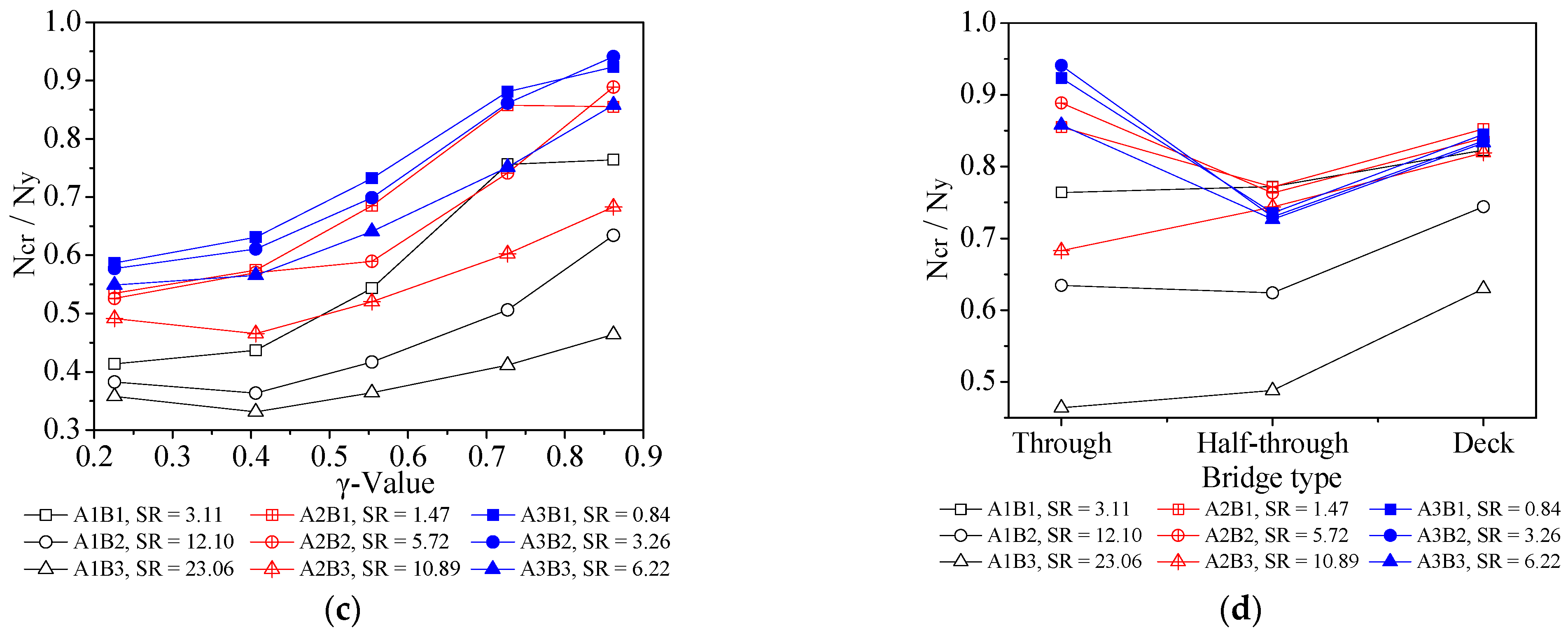
Since there are three different arch rib cross sections in nine FE analysis cases, and the critical axial force Ncr by FE analysis with different sections is not comparable, the Ncr of the arch rib is normalized for the purpose of discussion by the yield force Ny at the full-section yield of arch rib, which is the product of yield stress and cross-sectional area of an arch rib. When Ncr/Ny = 1, that is, when out-of-plane instability occurs, the full section of the arch springing reaches the yield strength of the material. The influences of rise-to-span ratio, arch rib spacing, and γ-value with different stiffness ratios on normalized critical axial forces for the through-type bridge (as representative of the three types) are shown in Figure 13a–c. The influence of bridge type is studied by translating the location of the girder framework, as already explained, and the critical axial force with different stiffness ratios is shown in Figure 13d. These figures show each arch rib type in a different color with the same fill. Cases with the same lateral bracing are notated by marks with the same shape. Figure 13 shows that Ncr/Ny ranges from 0.33 to 0.97 under different construction parameters; in other words, when the steel arch bridge occurs out-of-plane instability, the structural parameters have a great influence on whether the arch springing section yield or yield area, especially the parameter of lateral bracing arrangement range.
Figure 13a demonstrates that the change in the rise-to-span ratio exerts little influence on normalized critical axial force except in a few cases. This is because a decrease in the rise-to-span ratio leads to reduced critical flexure load but also makes the arch ribs more flat, which leads to an increase in the axial force in the arch rib. These two influences together cause a slight influence on the rise-to-span ratio on the normalized critical axial force. The influence of the rise-to-span ratio is taken into account in all three codes.
Figure 13b shows that the normalized critical axial force is slightly affected by arch rib spacing when the stiffness ratio is small. However, it decreases with increasing arch rib spacing when the stiffness ratio is relatively large. Since lateral bracing with the same cross-section becomes weaker as arch rib spacing increases, the deformation of arch ribs becomes less restrained. Consequently, the normalized critical axial force decreases, especially when lateral bracing is weak. The influence of arch rib spacing is taken into account in all three codes.
Figure 13 shows that the decreasing stiffness of lateral bracing for bridges with the same arch ribs will lead to a decrease in the normalized critical axial force. On the contrary, the normalized critical axial force tends to augment with falling arch rib stiffness when the lateral bracing is the same. The normalized critical axial force basically decreases with increasing stiffness ratio when the stiffness of the arch ribs and lateral bracing are simultaneously taken into account. In addition, as shown in Figure 13c, a smaller γ-value relating to the lateral bracing significantly reduces the normalized critical axial force. The Chinese and European codes consider the stiffness of both arch ribs and lateral bracing. The Japanese code considers the stiffness of the arch ribs, but parameters such as the arrangement of lateral bracing and the γ-value are not taken into consideration. Therefore, it can be anticipated that the out-of-plane critical axial force calculated with the Japanese code will not be conservative when the stiffness ratio is large or the γ-value is small [31,32].
Figure 13d demonstrates that compared with the other two types of steel arch bridges, the normalized critical axial force of a half-through type arch bridge is mostly smaller when the stiffness ratio is relatively small, while otherwise, it is similar to that of a through-type bridge. Since the girder framework of a half-through arch bridge is rigidly connected to the place near the arch springing, any deformation of the girder intensifies the lateral displacement of the arch ribs, which reduces their critical axial force. Moreover, the normalized critical axial force of a deck-type bridge is larger than that of a through-type bridge when the stiffness ratio is relatively large; otherwise, the normalized critical axial force of a through-type bridge is larger than that of a deck-type bridge. This is because the girder framework of a deck-type bridge has a certain positive effect on enhancing the out-of-plane stability, and the effect is more obvious when the stiffness ratio is relatively large. The type of bridge is considered in the Japanese and European codes but not in the Chinese code.

5. Evaluation of Major Design Codes Based on Results of FE Analysis

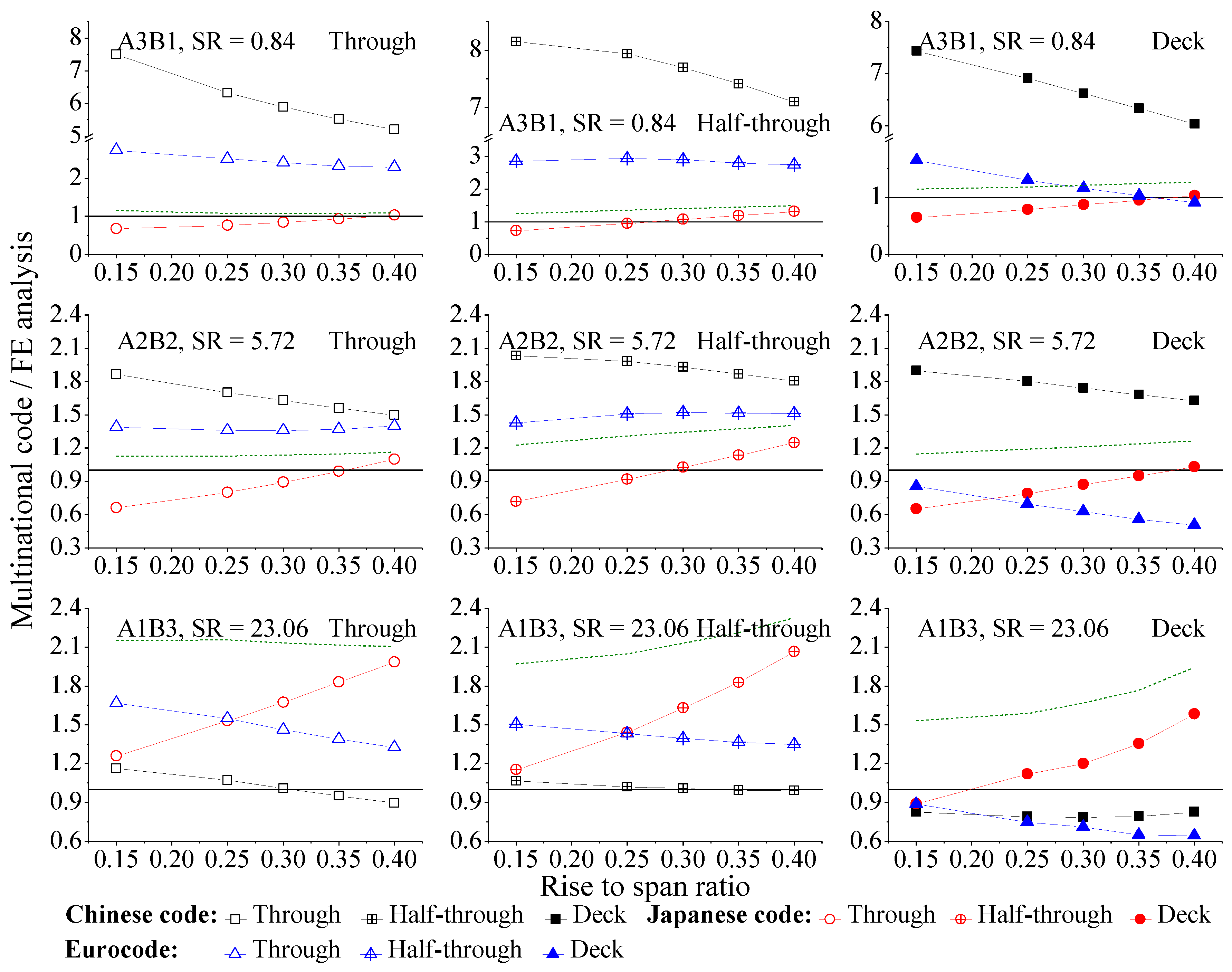
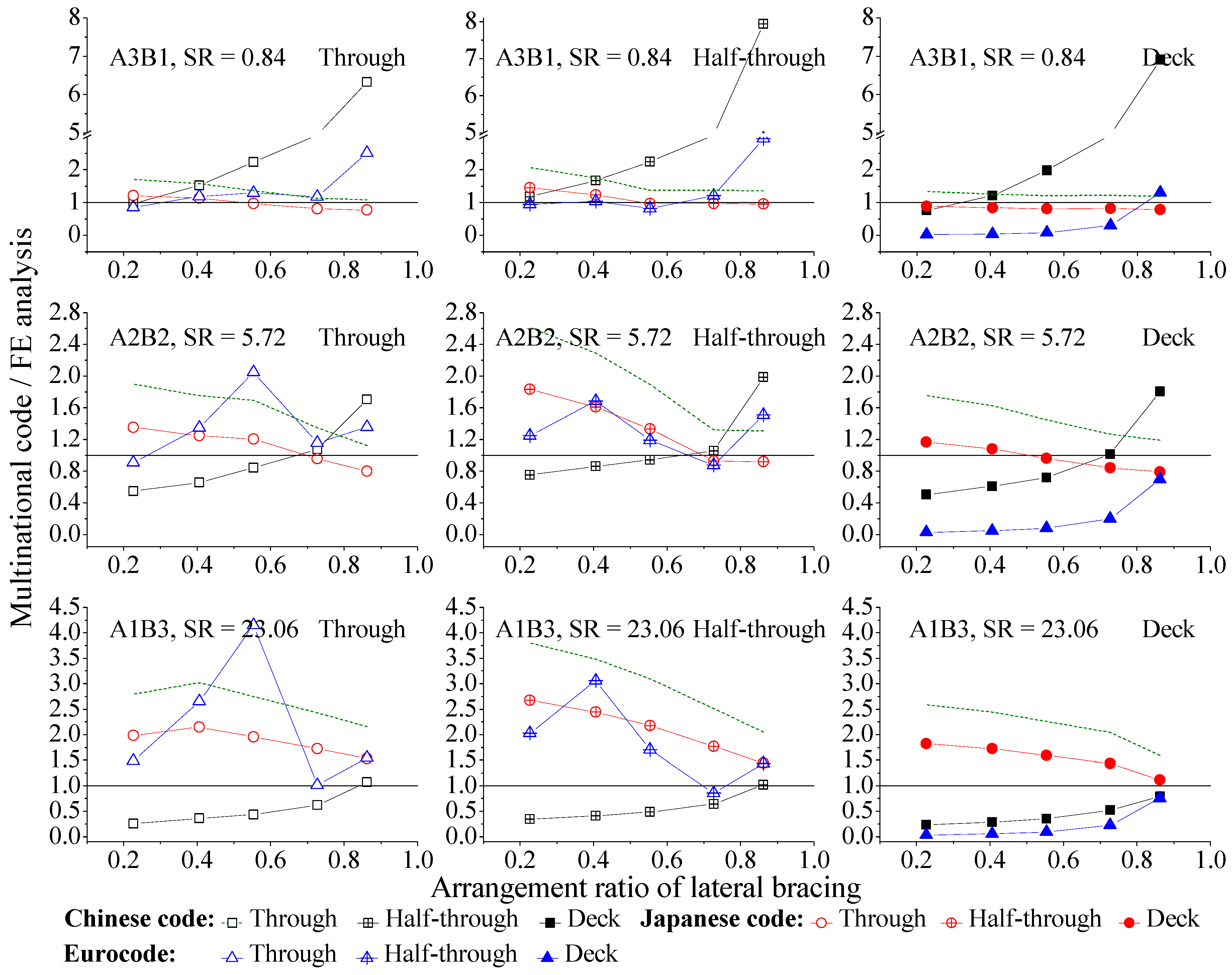
In this section, the critical axial force values of the arch rib according to the three codes are normalized and evaluated with respect to the FE analysis results considering the influence of certain parameters, as shown in Figure 9, Figure 10 and Figure 11. The effects of these parameters on normalized critical axial forces for three types of arch bridges are represented in these figures by three cases with small, medium, and larger stiffness ratios. The Y axes in the first row of graphs in each figure are split to show the results more clearly. The solid black line in the figures shows where the critical axial force according to the code equals that given by FE analysis. The olive-colored dashed line shows the yield force of the cross-section normalized by the results of the FE analysis. This can be thought of as the maximum value of strength in design practice.

5.1. Influence of Rise-to-Span Ratio

The influence of the rise-to-span ratio on the normalized critical axial force can be seen in Figure 14. In most cases, according to the Chinese and European codes, the normalized critical axial force slightly decreases with increasing rise-to-span ratio, while it increases with increasing rise-to-span ratio in the Japanese code. This rising tendency of the Japanese code is more apparent when the stiffness ratio is large. These findings indicate that the Chinese code and Eurocode overestimate the negative influence of the rise-to-span ratio on critical axial force, while the Japanese code underestimates it. They can be explained as follows. Since the rise-to-span ratio has only a slight influence on the critical axial force in the FE analysis results, the influence of the rise-to-span ratio on the normalized critical axial force is almost the same as on the critical axial force in the codes. Moreover, the influence of the rise-to-span ratio on the critical axial force in the codes can be explained as follows. The Chinese code treats the arch rib as a Vierendeel truss with the length of the arch axis, and the length of the arch axis s and panel length a increase with increasing rise-to-span ratio, thereby causing the decrease in critical axial force calculated by Equations (2)–(4). According to the Eurocode, the hr-value increases with increasing rise-to-span ratio, which leads to a higher β-value, so as to decrease the out-of-plane critical axial force obtained by Equation (9). The Japanese code provides that the βz-value in Equation (6) increases with increasing rise-to-span ratio, which results in a higher slenderness ratio of the arch rib, l/r, so the allowable axial compressive stress σca decreases slightly. These changes keep the horizontal component of arch axial force almost constant. However, the increases in the rise-to-span ratio led to the increasing angle between the arch axis and the horizontal; thus, the critical axial force increases.

5.2. Influence of Range of Lateral Bracing Arrangements

Figure 15 shows the effect of the γ-value on the normalized critical axial force for three types of bridges. It demonstrates that the normalized critical axial force tends to increase with increasing γ-value in the Chinese code and decrease in the Japanese code, respectively. This means that the Chinese and Japanese code overestimates and underestimates the positive effect of γ-value on the critical axial force, respectively. The critical axial force increases with increasing γ-value in the FE analysis results, and the same tendency is obtained by the Chinese code since the value of panel length a decreases with increasing γ-value. Therefore, the increase in γ-value leads to the increase in the normalized critical axial force in Chinese code. In the Japanese code, there is no parameter relating to the influence of lateral bracing, and thus the critical axial force, according to the Japanese code, is independent of the γ-value. Therefore, a larger γ-value reduces the normalized critical axial force in the Japanese code. Concerning the Eurocode, a tendency for normalized critical axial force to increase with increasing γ-value is observed for a deck-type bridge. In other words, the code overestimates the positive influence of the γ-value in the case of a deck-type bridge. However, this tendency is not the same for through and half-through types. In the Eurocode, the buckling length is determined by the product of β-value and height of the end portals h. A decrease in γ-value results in increased height h, which then leads to a decrease in β-value, as shown in Figure 7. Therefore, the change in critical axial force depends upon the amount of the reduction in β-value and the increment in h-value with decreasing γ-value. When the γ-value is in the range of 0.23 to 0.55 and 0.73 to 0.86 for a through-type bridge and in the range of 0.23 to 0.41 and 0.73 to 0.86 for a half-through type bridge, the reduction in β-value is larger than the increment in h-value, so the critical axial force increases with increasing γ-value. Otherwise, the critical axial force decreases with increasing γ-value. When the critical axial force is normalized by FE results, these increasing and decreasing tendencies are slightly reduced since the critical axial force by FE analysis increases with increasing γ-value, especially when the stiffness ratio is small. Therefore, the relationship between normalized critical axial force for through and half-through arch bridges and γ-value is not monotonous. However, for deck-type bridges, βh decreases with increasing γ-value as the reduction in β-value is much larger than the increment in the h-value, so the critical axial force for deck-type arch bridges increases with escalating γ-value. Further, owing to the relation between critical axial force in FE analysis and the γ-value, the normalized critical axial force for deck-type bridges increases with increasing γ-value in the Eurocode.

5.3. Influence of Arch Rib Spacing

The effects of arch rib spacing on the normalized critical axial forces of the three types of bridges are shown in Figure 16. The figure demonstrates that, according to the Chinese code, the normalized critical axial force reaches relatively small peaks when the stiffness ratio is at a certain arch rib spacing, while it decreases with increasing arch rib spacing when the stiffness ratio is relatively large. The arch rib spacing has a slight influence on normalized critical axial force according to the Japanese code. The normalized critical axial force specified by the Eurocode increases with decreasing arch rib spacing. Thus, the Chinese code overestimates the positive effect of arch rib spacing at smaller spacings and underestimates it at larger spacings when the stiffness ratio is small, while otherwise, the same as the Eurocode, underestimates the positive influences of arch rib spacing. The influence of arch rib spacing is estimated properly in the Japanese code, especially if the stiffness ratio is relatively small.
Two aspects of these results can be considered of crucial importance. On the one hand, arch rib spacing has a slight effect on the critical axial force, according to FE analysis. Therefore, the sensitivity of normalized critical axial stress to the variation of arch rib spacing is basically similar to the codes. On the other hand, the Chinese code takes arch rib spacing into account by adopting the geometrical moment of inertia of the two arch ribs I and their spacing b as parameters, while the influence of spacing b is factored by 1/Ib which relates to the stiffness of the lateral bracing. Therefore, when the stiffness ratio is relatively small, the dual effect of I and b results in a peak in critical axial force at certain spacing. Otherwise, spacing b is the main effect, which results in the critical axial force decreasing with increasing arch rib spacing. In the Eurocode, an increase in arch rib spacing causes the increase in η-value shown in Figure 5, which leads to a higher β-value and hence a reduced critical axial force of the arch rib. On the contrary, in the Japanese code, the integral lateral stiffness is taken into account while calculating the transverse radius of gyration, r, which means greater arch rib spacing results in greater integral lateral rigidity of the arch rib. Therefore, the critical flexure load according to the Japanese code increases with increasing arch rib spacing. However, the change is small.

5.4. Influence of Stiffness Ratio

We find from Figure 14, Figure 15 and Figure 16 that the stiffness ratio significantly affects the normalized critical axial force. The critical axial forces according to the Chinese and European codes are generally overestimated when the stiffness ratio is small, regardless of the rise-to-span ratio, arch rib spacing, and γ-value, even exceeding the normalized yield force, while it is relatively close to the results given by FE analysis when the stiffness ratio is large. The flexural stiffness of the arch rib and lateral bracing is considered simultaneously in the formulae given in the Chinese code and Eurocode for calculating the critical axial force as the Euler critical force. However, the positive effect of lateral bracing is overestimated. On the other hand, the influence of lateral bracing is not considered in the Japanese code provisions, and the critical axial force according to FE analysis decreases with increasing stiffness ratio. Therefore, the critical axial force obtained using the Japanese code is conservative when the stiffness ratio is small and overestimated when it is large, respectively. The normalized critical axial forces calculated by the Japanese code coincide with FE analysis results. Therefore, in general, the results given by the Japanese code are relatively accurate.

5.5. Influence of Bridge Type

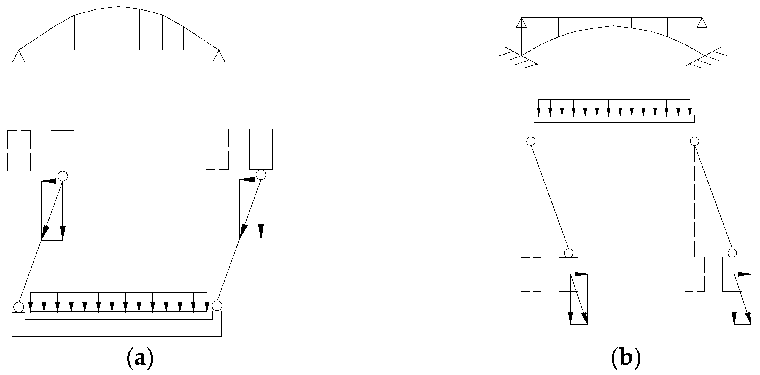
The Chinese code provides the same formulae for calculating the critical axial force for the three different types of arch bridges. The Japanese code assumes a different φ-value in Equation (6) to obtain the different effective lengths of arch rib for the three types of bridges, which then affects the allowable axial compression stress σca. Although the φ-value has a large effect on σca when the arch rib is slender, the influence of the φ-value in this study is negligible since the slenderness ratio of the arch rib is comparatively small. For these reasons, the effect of bridge type on normalized critical axial force according to the Chinese and Japanese codes should be contrary to that discussed in relation to the FE results in Section 4. This can be seen in Figure 14, Figure 15 and Figure 16. In the Eurocode, the positive effect of the horizontal component of tension in the hangers and the negative effect of the horizontal component of compression in the columns on the out-of-plane buckling of the arch ribs, as shown in Figure 17, are considered. Since the hanger and column lengths are treated as positive and negative values, respectively, when calculating the hr-value for different types of arch bridges, the hr-values for through and half-through type arch bridges are little different, while the hr-value for a deck-type bridge is smaller. For this purpose, the critical axial force for a through-type arch bridge is only slightly different from that for a half-through type arch bridge. Moreover, this conclusion is quite similar to the FE analysis results when the stiffness ratio is relatively large. Although the critical axial force for a through-type bridge is larger than that for a half-through type bridge in the FE analysis results when the stiffness ratio is relatively small, the critical axial force according to the Eurocode is much larger than that by FE analysis. For these reasons, the normalized critical axial force given by the Eurocode for through and half-through type bridges is almost the same, while the critical axial force for a deck-type bridge is much smaller.

5.6. Factors for Improving Code Accuracy

Equations (10)–(12) are proposed for improving the accuracy of critical axial force as given by the three codes. The yield force of the arch rib cross-section can be thought of as the maximum value of strength in design practice. Therefore, only critical axial forces given by the codes that are smaller than the yield force are formulated. In these equations, φr, φb, and φs are the critical axial force normalized by FE analysis, r is the stiffness ratio, R is the rise-to-span ratio, γ is the ratio of rib length provided with lateral bracing, as defined in Figure 7, and b is the arch rib spacing. The values of A, B, C, and D in Equations (10)–(12) are given in Table 4, Table 5 and Table 6, respectively. Since values of φb for through and half-through type bridges according to the Eurocode are difficult to fit using simple equations, they are excluded from Table 5.
ϕ r = A + B r + ( C + D r ) R
ϕ b = A + B r + ( C + D r ) γ
ϕ s = A + B r + ( C + D r ) b
To conform with earlier assumptions, these proposed equations are applicable to bridges with rise-to-span ratio, arch rib spacing, and γ-value in the range of 0.15 to 0.5, 6 m to 14 m, and 0.23 to 0.86, respectively, and only when the critical axial forces calculated by these codes are smaller than yield force. The accuracy of estimation is evaluated in Figure 18 by plotting estimation results against analysis results. Most of the analysis results are within an error of 15%, indicating that the proposed formulae can be considered valid. It should be pointed out that the proposed equations require further validation for original models that are different since all the other parameters are kept the same as those of the original model when discussing the influence of one parameter.

6. Conclusions

The accuracy of provisions for the out-of-plane stability of steel arch bridges in major design codes was evaluated using the results of FE analysis. Summaries of this work are shown as follows.
(1) According to FE analysis, the influence of the rise-to-span ratio on critical axial force is generally small. The critical axial force decreases with increasing arch rib spacing when the stiffness ratio is relatively large. A smaller ratio of arch rib length provided with lateral bracing (γ-value) significantly reduces the critical axial force, and normalized critical axial force decreases with increasing stiffness ratio. The critical axial force of half-through type arch bridges is lowest when the stiffness ratio is relatively small. A deck-type bridge has a larger critical axial force than a through-type bridge when the stiffness ratio is relatively large, while the results are the opposite when the ratio is small.
(2) The Chinese code generally overestimates the critical axial force when the γ-value is more than 0.86 and otherwise underestimates it, except in cases with a smaller stiffness ratio. The code also overestimates the positive effect of the γ-value and the negative effects of the rise-to-span ratio and stiffness ratio. The effect of arch rib spacing is estimated to be non-monotonous when the stiffness ratio is small. Otherwise, the negative effects are overestimated. The influence of bridge type is properly evaluated.
(3) The Japanese code accurately estimates the critical axial force when the stiffness ratio is small and otherwise overestimates it. The positive effects of the rise-to-span ratio and stiffness ratio, and the negative impact of γ-value, are overestimated. The influence of bridge type and arch rib spacing is properly evaluated.
(4) The Eurocode generally underestimates the critical axial force for deck-type bridges. It accurately estimates the critical axial force for through and half-through type bridges when the stiffness ratio is small and the γ-value is smaller than 0.86, and otherwise mostly overestimates it. The Eurocode also overestimates the negative effects of the rise-to-span ratio, arch rib spacing, and stiffness ratio. The effect of γ-value on through and half-through type bridges is estimated to be non-monotonous, while the positive effect of γ-value is overestimated for deck-type bridges.
(5) Considering the influence of the rise-to-span ratio, the ratio of lateral bracing, and arch rib spacing with different stiffness ratios, factors to improve the accuracy of the critical axial force obtained by the three codes are proposed for a practical design process. The accuracy of these proposed corrections is verified.

Author Contributions

W.W. and K.C. conceived the analyses; W.W., Y.L. and K.C. performed the finite element analysis and analyzed the data; K.C. contributed materials/analysis tools, and W.W. wrote the paper. All authors have read and agreed to the published version of the manuscript.

Funding

This research was funded by the Natural Science Foundation of Fujian Province (No. 2021J011059) and the Research Start-up Fund of Fujian University of Technology (No. GY-Z20015).

Data Availability Statement

The data presented in this study are available on request from the corresponding author.

Acknowledgments

The authors acknowledge the funding from the Natural Science Foundation of Fujian Province (No. 2021J011059) and the Research Start-up Fund of Fujian University of Technology (No. GY-Z20015). The authors acknowledge the support from Shozo Nakamura from Nagasaki University, Japan.

Conflicts of Interest

The authors declare no conflict of interest.

References

  1. Timoshenko, S.; Gere, J. Theory of Elastic Stability, 2nd ed.; McGraw-Hill: New York, NY, USA, 1961. [Google Scholar]
  2. Demuts, E. Lateral Buckling of Circular Arches Subjected to Uniform Gravity Type Loading. Ph.D. Thesis, Ohio State University, Columbus, OH, USA, 1969. [Google Scholar]
  3. Lu, H.; Liu, A.; Bradford, M.A.; Pi, Y. Experimental investigation of out-of-plane buckling of circular arches under a central radial point load. Thin-Walled Struct. 2020, 148, 106198. [Google Scholar] [CrossRef]
  4. Tokarz, F.J.; Sandhu, R.S. Lateral-torsional buckling of parabolic arches. J. Struct. Div. 1972, 98, 1161–1179. [Google Scholar] [CrossRef]
  5. Kee, C.F. Lateral inelastic buckling of tied arches. J. Struct. Div. 1961, 87, 23–40. [Google Scholar] [CrossRef]
  6. Tokarz, F.J. Experimental Study of Lateral Buckling of Arches. J. Struct. Div. 1971, 97, 545–559. [Google Scholar] [CrossRef]
  7. Papangelis, J.P.; Trahair, N.S. Flexural-torsional buckling tests on arches. J. Struct. Eng. 1987, 113, 1433–1443. [Google Scholar] [CrossRef]
  8. Papangelis, J.P.; Trahair, N.S. Flexural-torsional buckling of arches. J. Struct. Eng. 1987, 113, 889–906. [Google Scholar] [CrossRef]
  9. Almeida, P.N. Lateral Buckling of Twin Arch Ribs with Transverse Bars. Ph.D. Thesis, Ohio State University, Columbus, OH, USA, 1970. [Google Scholar]
  10. Sakimoto, T.; Namita, Y. Out-of-plane buckling of solid rib arches braced with transverse bars. Proc. Jpn. Soc. Civ. Eng. 1971, 191, 109–116. [Google Scholar] [CrossRef] [PubMed] [Green Version]
  11. Sakimoto, T.; Komatsu, S. A possibility of total breakdown of bridge arches due to buckling of lateral bracings. In Proceedings of the Final Report of the 2nd International Colloquium on Stability of Steel Structures, Liege, Belgium, 13–15 April 1977; pp. 299–301. [Google Scholar]
  12. Kuranishi, S.; Yabuki, T. Required out-of-plane rigidities of steel arch bridge with two main ribs subjected to vertical and lateral loads. Technol. Rep. Tohoku Univ. 1977, 46, 47–72. [Google Scholar]
  13. Guo, Y.; Zhao, S.; Dou, C. Out-of-plane elastic buckling behavior of hinged planar truss arch with lateral bracings. J. Constr. Steel Res. 2014, 95, 290–299. [Google Scholar] [CrossRef]
  14. Sakimoto, T.; Komatsu, S. Ultimate strength of arches with bracing systems. J. Struct. Div. 1982, 108, 1064–1076. [Google Scholar] [CrossRef]
  15. Sakimoto, T.; Komatsu, S. Ultimate strength formula for steel arches. J. Struct. Div. 1983, 109, 613–627. [Google Scholar] [CrossRef]
  16. Sakimoto, T.; Sakata, T.; Kobori, T. An effective length procedure for out-of-plane buckling strength estimation of steel arch bridges. In Proceedings of the 3rd Pacific Structural Steel Conference, Tokyo, Japan, 26–28 October 1992. [Google Scholar]
  17. Pi, Y.L.; Trahair, N.S. Out-of-Plane Inelastic Buckling and Ultimate Strength of Steel Arches; Research Report No. R737; University of Sydney: Camperdown, NSW, Australia, 1997. [Google Scholar]
  18. Lim, N.H.; Kang, Y.J. Out of plane stability of circular arches. Int. J. Mech. Sci. 2004, 46, 1115–1137. [Google Scholar] [CrossRef]
  19. Pi, Y.L.; Bradford, M.A. Out-of-plane strength design of fixed steel I-section arches. J. Struct. Eng. 2005, 131, 560–568. [Google Scholar] [CrossRef]
  20. Spoorenberg, R.C.; Snijder, H.H.; Hoenderkamp, J.C.D. A theoretical method for calculating the collapse load of steel circular arches. Eng. Struct. 2012, 38, 89–103. [Google Scholar] [CrossRef] [Green Version]
  21. Liu, A. Experimental research on stable ultimate bearing capacity of leaning-type arch rib systems. J. Constr. Steel Res. 2015, 114, 281–292. [Google Scholar] [CrossRef]
  22. Bouras, Y.; Vrcelj, Z. Out-of-plane stability of concrete-filled steel tubular arches at elevated temperatures. Int. J. Mech. Sci. 2020, 187, 105916. [Google Scholar] [CrossRef]
  23. Zhong, Z.; Liu, A.; Fu, J.; Lin, P.; Jian, D.; Xie, Z. Analytical and experimental studies on out-of-plane dynamic parametric instability of a circular arch under a vertical harmonic base excitation. J. Sound Vib. 2021, 500, 116011. [Google Scholar] [CrossRef]
  24. Chan, S. Non-linear behavior and design of steel structures. J. Constr. Steel Res. 2001, 57, 1217–1231. [Google Scholar] [CrossRef]
  25. Standardization Administration of the People’s Republic of China. Fundamental Code for Design on Railway Bridge and Culvert; China Railway Publishing House Co., LTD.: Beijing, China, 2005. [Google Scholar]
  26. Japan Road Association. Specifications for Highway Bridges Part II; Marusan Publishing Division: Tokyo, Japan, 2012. [Google Scholar]
  27. European Committee for Standardization. Eurocode3: Design of Steel Structures-Part 2: Steel Bridge; European Committee for Standardization: Brussels, Belgium, 2003. [Google Scholar]
  28. American Association of State Highway and Transportation Officials. LRFD Bridge Design Specifications; American Association of State Highway and Transportation Officials: Washington, DC, USA, 2010.
  29. Wan, P. Research on Synthetical Three Factors Check Method for Ultimate Load Carrying Capacity of Long-Span Steel Arch Bridges. Ph.D. Thesis, Southwest Jiaotong University, Chendu, China, 2005. [Google Scholar]
  30. Usami, T. Guidelines for Stability Design of Steel Structures; Marusan Publishing Division: Tokyo, Japan, 2005. [Google Scholar]
  31. Sakimoto, T.; Sakata, T. The out-of-plane buckling strength of through-type arch bridges. J. Constr. Steel Res. 1990, 16, 307–318. [Google Scholar] [CrossRef]
  32. Sakimoto, T.; Sakata, T.; Tsuruta, E. Elastic-plastic out-of-plane buckling strength of through type and half-through type arch bridges. Struct. Eng./Earthq. Eng. 1989, 2, 137–148. [Google Scholar]
Figure 1. Out-of-plane Instability of Steel Arch Bridge: (a) Vertical View; (b) Lateral View.
Applsci 12 12632 g001
Figure 4. Buckling of Portals for Arches.
Applsci 12 12632 g004
Figure 5. Buckling Length Factors β: (a) Arch Springing Hinged; (b) Arch Springing Fixed; and (c) Arch Springing with Wind Brace.
Applsci 12 12632 g005
Figure 6. Photo of Manzeki Bridge.
Applsci 12 12632 g006
Figure 7. Geometric Notation for Coefficient γ: (a) General View; and (b) Elevation View.
Applsci 12 12632 g007
Figure 8. FE Model of Steel Arch Bridge: (a) FE Model Meshing; (b) Full-span Uniform Loading; (c) Through-Type Bridge; (d) Half-through Type Bridge; (e) Deck-Type Bridge.
Applsci 12 12632 g008
Figure 9. Material Model.
Applsci 12 12632 g009
Figure 10. Test Specimen and Loading Photo.
Applsci 12 12632 g010
Figure 11. Comparison of Test and FE Analysis results.
Applsci 12 12632 g011
Figure 12. FE Analysis Result of A FE Model: (a) Relation Curve between the Axial Force at the Springing and the Horizontal Displacement at Vault; (b) Out-of-plane Instability Mode of Arch Rib.
Applsci 12 12632 g012
Figure 13. Influence of Parameters on Normalized Critical Axial Forces by FE Analysis: (a) Influence of Rise-to-span; (b) Influence of Arch Rib Spacing; (c) Influence γ-value; (d) Influence of Bridge Type.
Applsci 12 12632 g013aApplsci 12 12632 g013b
Figure 14. Accuracy Evaluation of Multinational Codes on Influence of Rise-to-span Ratio.
Applsci 12 12632 g014
Figure 15. Accuracy Evaluation of Multinational Codes on Influence of γ-value.
Applsci 12 12632 g015
Figure 16. Accuracy Evaluation of Multinational Codes on Influence of Arch Rib Spacing.
Applsci 12 12632 g016
Figure 17. Influence of Hanger and Shoring on the Out-of-plane Buckling: (a) Through-Type Arch Bridge; (b) Deck-Type Arch Bridge.
Applsci 12 12632 g017
Figure 18. Estimation Accuracy: (a) Influence of Rise-to-span Ratio; (b) Influence of γ-value; (c) Influence of Arch Rib Spacing.
Applsci 12 12632 g018
Table 1. Value of βz.
SectionRise Ratio f/L
0.050.100.200.300.40
Iy = constant0.500.540.650.821.07
Iy = Iy,c/cosφm0.500.520.590.710.86
Table 2. Cross Section of Arch Rib and Lateral Brace (Unit: mm).
SectionHeightWidthThickness of FlangeThickness of Web Plate
Arch rib 1175211002626
Arch rib 2120010002220
Arch rib 310009002016
Lateral brace 110009001815
Lateral brace 27006001412
Lateral brace 36005001210
Table 3. Study Cases for Each Parameter on Each Object Bridge.
Case010203040506070809
Section of arch rib123
Section of lateral brace123123123
Stiffness ratio3.1112.1023.061.475.7210.890.843.266.22
Table 4. Value of Factor φr.
CodeBridge TypeABCD
Chinese codeThrough1.602−0.008−0.919−0.009
Half-through1.751−0.025−0.7780.015
Deck1.704−0.036−1.1790.044
Japanese codeThrough0.2670.0221.5060.063
Half-through0.3600.0102.1400.046
Deck0.4130.0031.553−0.007
EurocodeThrough0.7510.0510.712−0.091
Half-through0.7680.0341.593−0.178
Deck0.9290.001−1.4360.016
Table 5. Value of Factor φb.
CodeBridge TypeABCD
Chinese codeThrough0.333 −0.012 1.193 −0.020
Half-through0.530 −0.015 1.212 −0.030
Deck0.275 −0.008 1.215 −0.034
Japanese codeThrough1.356 0.039 −0.811 0.001
Half-through1.629 0.076 −1.018 −0.053
Deck0.899 0.050 −0.228 −0.035
EurocodeDeck−0.048 −0.001 0.187 0.008
Table 6. Value of Factor φs.
CodeBridge TypeABCD
Chinese codeThrough1.848−0.001−0.058−0.001
Half-through2.922−0.044−0.1160.002
Deck2.658−0.050−0.1100.002
Japanese codeThrough0.6630.0150.0040.002
Half-through0.7780.0070.0060.002
Deck0.603−0.0020.0120.002
EurocodeThrough1.978−0.011−0.0880.003
Half-through2.563−0.042−0.1250.005
Deck0.974−0.014−0.0330.001
Publisher’s Note: MDPI stays neutral with regard to jurisdictional claims in published maps and institutional affiliations.