Abstract
Bone tissue engineering (BTE) is an interdisciplinary discipline that focuses on bone structure–function relationships for improving the replacement and/or regeneration of bone tissues. Thereby, the architecture and load-bearing capacity of embedded scaffolds play an important role in the generation of artificial tissues. The aim of this study was to develop a parametric numerical model and the accompanying fabrication of polycaprolactone (PCL) scaffolds for BTE applications. Therefore, we manufactured layered PCL-based constructs using three-dimensional (3D) printing. The material properties of PCL and constructs were determined by mechanical testing, and numerical models based on Beam188 Timoshenko elements were developed in the software environment ANSYS. PCL constructs were coated with collagen and seeded with osteoblasts, mesenchymal stem cells (MSCs), MLO-Y4 and MG63 cell types. We demonstrated the successful production of PCL constructs with 3D interconnected pores suitable for BTE applications. Furthermore, we provided for the first time geometrical parametric numerical models that determined the mechanical behavior of layered PCL scaffolds consisting of interconnected compartments for strains up to 3%. The parametric structures of the model allowed us to flexibly study new geometries in silico, which demonstrated its role as an important tool for supporting the fabrication of customized PCL constructs in planning and performing suitable mechanical characterizations for BTE applications.
1. Introduction
Bone tissue engineering (BTE) is an interdisciplinary field in which physicians, biologists and engineers collaborate to develop and produce artificial bone tissues [1]. One common strategy for the treatment of bone defects are in vitro applications of cultured autologous cells or stem cells on scaffolds followed by the implantation into specific tissues and tissue regions. Thereby, scaffolds play key roles, serving to mimic physiological in situ environments [2]. For this reason, they should have high interconnectivity, high porosity, good biocompatibility, as well as sufficient mechanical strength and reliability [3]. Besides metals and ceramics [4], plastic polymers such as Polycaprolactone (PCL) are in use as materials for the production of these three-dimensional (3D) structures [5].
PCL is a 3D-printable semi crystalline synthetic polymer that can be reversibly deformed in certain temperature ranges [6,7,8]. Thereby, the melting point reaches from 55 to 63 °C [9]. PCL shows viscoelastic behavior [10] and a good biocompatibility [11]. Pure PCL is hydrophobic, which can negatively affect cell adhesion and cell proliferation [12,13]. Scaffolds can be manufactured using additive producing processes, which are also coined as 3D printing. Hereby, products are created by adding the material step by step. Thereby, the geometry of the scaffolds is modeled using computer-aided design (CAD) software [14]. Single layers can be produced by heated viscous materials that are pressed out of a needle by compressed air. The final construct geometry is created by stacking the PCL layers “layer by layer” [15]. A widely used method allowing the approximation of mechanical and structural behaviors via numerically solving partial differential equations in engineering and BTE is the finite element method (FEM). Hereby, in contrast to classical numerical approaches, the function is not defined over the entire functional area but is divided into a finite number of subareas. With a parametric FEM design, geometric and material properties can be varied [16,17]. In this study, we aimed to develop a parametric model for layered, 3D-printed PCL scaffolds, consisting of interconnected compartments. This kind of scaffold allows the development of 3D networks of cells. As architecture plays a crucial role for the successful development and usage of these layered scaffolds, a suitable and flexible numerical in silico twin can be an important tool [18,19,20,21]. Currently, there are no parametric numerical models available for such scaffolds.
2. Materials and Methods
2.1. Fabrication of Scaffolds
PCL scaffolds were produced with a 3D-Bioplotter-System (ET.B4.16.11.M092, Envisiontec, Gladbeck, Germany) using PCL (Mn = 45,000, Sigma-Aldrich, St. Louis, MA, USA) and 24 G stainless steel needle tops (Envisiontec, Gladbeck, Germany). 3D printings were performed with process temperatures of 80 °C, platform temperatures of 18 °C, pressures of 4 bar, pre- and post-flow times of 0.4 s, needle offsets of 0.2 mm and speed of 0.5 mm/s.
Collagen coating of scaffolds was performed as previously described [12,22]. In detail, as a first step, scaffolds were washed with ethanol (30, 50, 70, 80, 96 and 100%, for five seconds each). To improve cell–scaffold interaction, polar oxygen groups were created on PCL surfaces, using plasma devices (PiezoBrush PZ2, Relyon Plasma, Regensburg, Germany) [23,24]. Following this, collagen coating was performed in 24-well plates (Costar, Merck, Darmstadt, Germany) in collagen solutions (concentration: 3.82 mg/mL; Rat Tail Collagen Type I, Corning, Corning, NY, USA) for 72 h at 5 °C. Next, scaffolds were dried for 24 h at 37 °C. Crosslinking of collagen was performed using a 95% ethanol, 50 mM 1-ethyl-3-carbodiimid in water solution.
2.2. Cell Seeding
MG-63 (MG63 ATCC CRL-1427, ATCC, Manassas, VI,), human osteoblasts, MLO-Y4 cells (MLO-Y4 EKC002, Kerafast, Boston, MA, USA) and MSC were used for the present work. MG-63 cells were purchased from ATCC and MLO-Y4 cells from Kerafast. In addition, MSC from human bone marrow and human osteoblasts from tibia resections (total knee arthroplasty) were used. Ethical approval was granted as ethics vote “FREEZE” by the Ethics Committee of the University Medical Center Freiburg. In a previous work, we observed different cell growth on collagen-I-coated PCL scaffolds for different cells [25].
Scaffolds were seeded with MG63 cells (MG63 ATCC CRL-1427, ATCC), MLO-Y4 cells (MLO-Y4 EKC002, Kerafast), mesenchymal stem cells (MSC) and osteoblasts in 24-well plates. MSC and osteoblasts were gained during operative hip surgery from proximal femur tissue. Second passage of cells was used. Cells were cultured in 75 cm2 flasks (Cellstar, Greiner Bio-One, Frickenhausen, Germany) at 37 °C with 5% CO2 in specific nutrient solutions (see Supplementary Table S1). Osteoblasts, MG63 and MLO-Y4 cells were digested using 3 mL Trypsin-EDTA (Merck, Darmstadt, Germany), MSC using 5 mL Accutase (Sigma-Aldrich). Following this, cells were counted in a Neubauer counting chamber and diluted with nutrient solutions to the aimed cell concentrations (Osteoblasts, MG63 and MLO-Y4 cells: 50.000 cells/100 μL; MSC: 50.000 cells/100 μL). Subsequently 100 μL of the cell-containing dilution was dribbled on the scaffolds and incubated at 37 °C with 5% CO2 for 2 h. Following this, 1 mL of the cell-containing dilution was added to the wells, and specimens were further incubated at 37 °C with 5% CO2. Nutrient solutions were exchanged every 3 days. PCL scaffolds were stained with 1:10 diluted Giemsa staining and Live-Dead-Assays (Live/Dead Cell Staining Kit II, PromoCell, Heidelberg, Germany). Images were obtained using microscopes (Olympus BX51, KEYNECE Germany, Neu-Isenburg, Germany) with associated fluorescent lamps (X-Cities Series 1207, KEYNECE Germany, Neu-Isenburg, Germany). Collagen coating was assessed using electron microscopes (ESEM FEI Quanta 250 FEG; FEI, Hilsboro, TX, USA).
2.3. Characterization of Scaffolds
Geometrical properties of scaffolds were determined with a Keyence VK-X200 Series laser microscope (KEYENCE, Tokyo, Japan). The assessment approach is given in Figure 1.
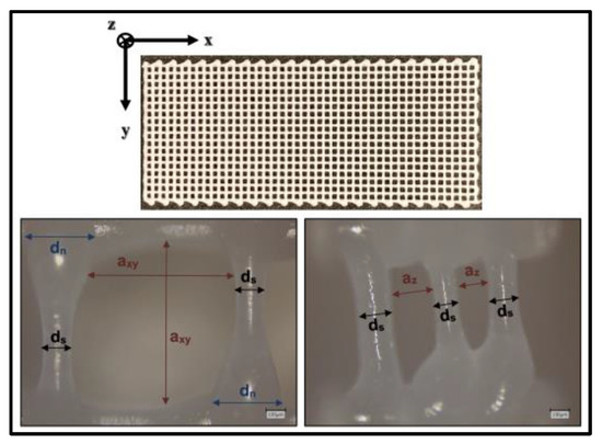
Figure 1.
Geometrical properties of PCL scaffolds. dn: Diameter of PCL struts in node areas; ds: Diameter of PCL struts in areas distant from nodes; axy: Clear width between two struts in xy plane; az: Clear width between two struts in z direction.
Material properties of PCL were determined via tensile testing according to DIN EN-ISO-527-1 with a Z005-testing machine (Zwick/Roell, Zwick/Roell GmbH & Co. KG, Ulm, Germany) standardized test body shape: 5A, manufacturing temperature: 80 °C, test temperature: 23 °C, Testing speed: 10 mm/min). Further creep testing of PCL was performed with an MCR 702 MultiDrive system (Anton Paar GmbH, Graz, Austria, solid rectangular fixture 5, creep stress = 1 N/mm2, nitrogen atmosphere, manufacturing temperature: 80 °C, test temperature: 23 °C, test body shape: 35 mm × 14 mm × 2.5 mm).
Tensile testing of scaffolds was executed within 24 h after production with Zwick and Bose testing machines (BPS-LH0010.21.00, Bose, Friedrichsdorf, Germany) test temperature: 23 °C, Testing speed: 10 mm/min).
2.4. Finite Element Method
Parametric FEM simulations were performed using ANSYS Mechanical APDL R1. The following assumptions for the numerical models were made: struts are idealized as beam elements; cross-sections are assumed to be ideally round and were modelled as solid cross-sections with variable diameters; material properties are constant and isotropic; a consistent distance between struts and rigid connections between struts are assumed. Table 1 gives the geometric parameters of the numerical models:

Table 1.
Geometric parameters of numerical models.
FEM models of PCL scaffolds were implemented based on three-dimensional 2 nodes Beam188 Timoshenko elements, which can model normal and shear forces and bending moments. In contrast to Bernoulli elements, no shear rigidity of the cross-sections is assumed. Thus, stocky geometries can also be analyzed [26]. The size of elements were varied via the variable “element_size”. Parameterized geometries of numerical models were defined via key points and generated via lines. The basic geometric development is illustrated in Supplementary Figure S1. Elastic-plastic and viscoelastic material models based on a Prony-Row were implemented [27,28]. Material properties were implemented via the variables “emodulus_pcl”,”f_y”, “prony_value” and “prony_time”. Loads were applied as path-controlled node loads. The basic structure of a numerical model and the comparison of the scaffold and model node areas are demonstrated in Figure 2.
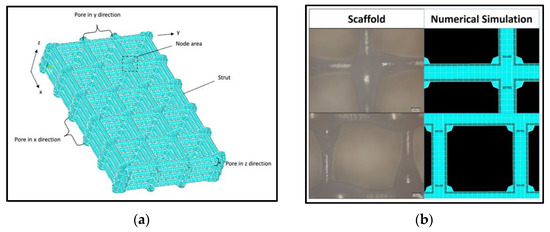
Figure 2.
Geometrical structure of numerical model: (a) Exemplary structure of a model with five pores in x direction (number_x = 5) and three pores each in y and z direction (number_y = number_z = 3); (b) Comparison of fabricated PCL scaffold and numerical FEM model.
For validation of the numerical model, the following force ratios between the results from the tensile testing of scaffolds and numerically determined values were defined ( = strain, n = number of tensile tests). Equation (1) is defined as the ratio between the determined force during the tensile testing and the numerical calculated force at a certain strain. Equation (2) describes the average of Equation (1) for 1%, 2% and 3% strains. Ratio (3) is the ratio of the average of all tensile testing and the numerical determined force.
2.5. Statistical Analysis
Statistical analyses were performed using IRIS RheoHub 2018, Origin 2019, Excel 2017 and SPSS 26. All values in this paper are expressed as mean ± standard deviation.
3. Results
The results of the geometrical characterization of ten scaffolds printed on different days are shown as boxplots in Figure 3, demonstrating mean pore sizes of about 800 ± 52 μm in the xy plane and 197 ± 20 μm in the z direction. The mean thickness of the struts was 143 ± 26 μm and the nodes areas showed a mean diameter of 338 ± 43 μm.
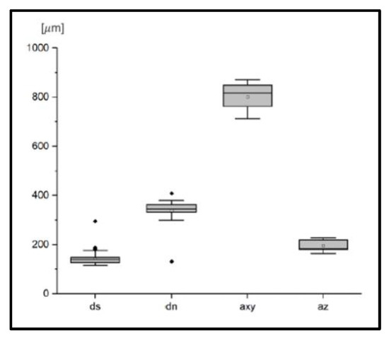
Figure 3.
Geometrical characterization of PCL scaffolds. dn: Diameter of PCL struts in node areas; ds: Diameter of PCL struts in areas distant from nodes; axy: Clear width between two struts in xy plane; az: Clear width between two struts in z direction.
Overall, six PCL samples were tensile tested. The mean Young’s modulus of the PCL was 566 ± 45 N/mm2, the mean yield strength was determined to be 17.9 ± 1.0 N/mm2 and the mean strain at yield strength was 8.8 + 2.1%. Associated stress–strain diagrams are provided in Figure 4.
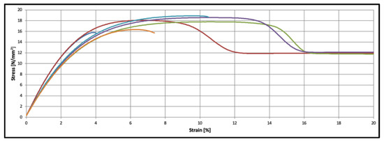
Figure 4.
Material characteristics of PCL specimens (n = 6).
The resulting Prony terms of the creep testing with a duration of 27 h are provided in Table 2.
Table 2.
Prony terms of PCL. Pa = Pascal, sec = seconds.
PCL scaffolds show an almost linear-elastic behavior up to tensile strains of 3%. From an elongation of 5% stress, the data show a plastic behavior. The mechanical behavior of PCL scaffolds is shown in Figure 5.
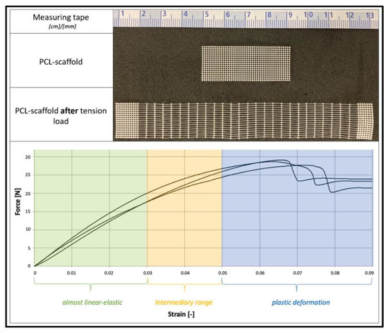
Figure 5.
Mechanical behavior of PCL scaffolds. Top: PCL scaffold before and after tension load. Bottom: Force–Strain diagram.
Numerical calculations based on Timoshenko Beam188 elements (element sizes: a_xy/16) show valid results with a force ratio of = 1.0515 ( = 1.0049, = 1.0412, = 1.1083). Thereby, the numerical results show stable results, independent of the implemented element types (rods vs. beams), grade of element functions (Beam188 vs. Beam189), size of elements and material laws (viscoelastic vs. elastic-plastic). The related data are provided in Supplementary Table S2.
The parameters of numerical models can be varied. Figure 6 shows exemplary effects of strut thicknesses on numerical results.
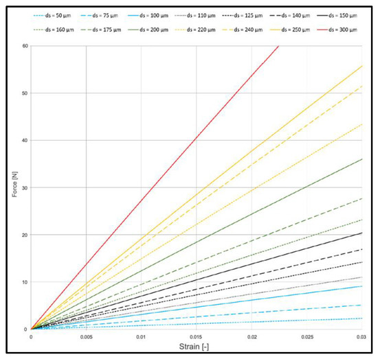
Figure 6.
Effect on strut thickness on mechanical behavior of PCL scaffolds (viscoelastic FEM model).
Studies with electronic microscopes show continuous collagen cover layers on all struts of PCL scaffolds. This is illustrated in Figure 7, showing, on the left side, a PCL scaffold before collagen coating and, on the right side, a PCL scaffold after coating. Without treatment with plasma devices, no collagen coating could be achieved due to less adherence on the PCL surface.
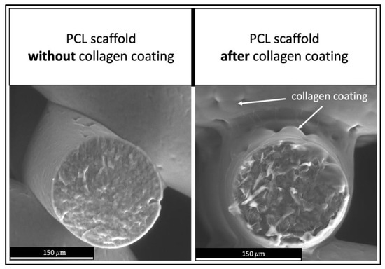
Figure 7.
Collagen coating on PCL scaffolds. Left: PCL scaffold before collagen coating. Right: PCL scaffold after coating process.
MG63 cells, MLO-Y4 cells and MSC were marked via Giemsa staining on all PCL scaffold struts after three days of incubation, illustrated in Figure 8. MG63 cells exhibited the highest cell density on scaffolds. In preliminary tests, no cell growth was observed on specimens not coated with collagen.
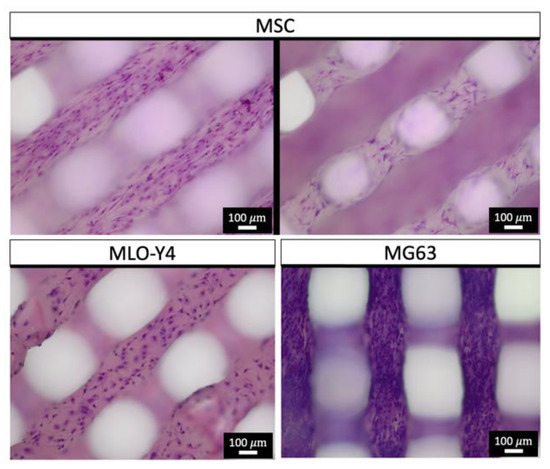
Figure 8.
Giemsa staining (chromatin—purple) of PCL scaffolds after three days of cell growth.
The growth of osteoblasts after three, seven and ten days is demonstrated in Figure 9. The Live/Dead (L/D) assays show vital osteoblasts in both strut and nodal areas of the PCL scaffolds. Further images of L/D assays of osteoblast-seeded scaffolds are provided in Supplementary Figure S3.
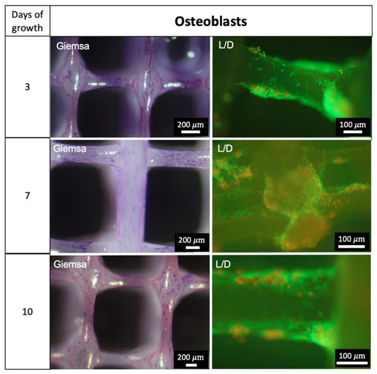
Figure 9.
Growth of Osteoblasts. Giemsa staining: chromatin—purple; L/D = Live/Dead Assay: Green—vital cells, red—dead cells.
4. Discussion
The principal new finding of this study is the development of parameter-based numerical models for layered 3D-printed PCL scaffolds consisting of interconnected compartments. These in silico digital twins allow a fast, flexible and targeted scaffold design and production while conserving resources.
3D FEM models have been developed to describe the mechanical behavior of bone, cartilage and of scaffolds in BTE applications [29]. This is usually followed by creating 3D computer-aided design (CAD) models for 3D printing processes. The resulting datasets are commonly used as geometrical information for numerical FE simulations during preprocessing. Reversing that classical workflow, the use of parametric geometrical approaches allows us to widely vary these geometries to identify optimal structural shapes prior to fabrication. Such parametric geometrical numerical models are used in BTE applications, e.g., for describing human femur models [30], orthopedic implants [31] and the design of scaffolds [32]. Importantly, no parametric geometrical modeling studies for layered scaffolds based on PCL are available. So far, only a few FEM models for PCL have been reported. Those either focus on the influence of the unit cell, porosity and needle diameter [20] on the mechanical behavior, or the addition of calcium phosphates [33] or nanohydroxyapatite to improve biocompatibility [34]. In these studies, the compressive strength of the entire layered scaffold was investigated. Here, we fabricated layered PCL scaffolds with interconnected compartments and developed for the first time geometrical parametric numerical models that determined the mechanical behavior of such scaffolds. The rationale for developing layered PCL scaffolds with interconnected compartments is their flexible properties and applications, despite their simple manufacturing method. Compartments can be filled with growth factors, hydrogels, fluids or drugs and enable three dimensionally connected cell growths [18,19,20,21].
FEM is an established numerical approach that is used to determine forces, stresses and stains [16,17]. Due to its compact geometry, the developed parameterized numerical models were implemented based on Beam188 Timoshenko elements. Comparative calculations with Strut-Elements and Euler–Bernoulli beams do not show considerable differences under the chosen boundary conditions. This is due to the fact that the length-to-width ratio is at a border between the use of Timoshenko and Euler–Bernoulli theory. Furthermore, the pure tensile load of elements under the present boundary conditions leads to the classical tensile strut behavior of the model. The developed numerical model allows for the flexibility study of different geometries in silico to specifically plan the load testing of PCL scaffolds. This is particularly relevant for studies with osteoblasts, as they react specifically to mechanical stimulations [35,36].
Furthermore, we demonstrated the successful development and additive fabrication of layered scaffolds based on PCL [11,37,38], but with specific architectures that included interconnected compartments. In a previous study, we demonstrated that variations in the architectural design of tissue-engineered constructs, combined with choosing specific biomaterial properties, can strongly influence the biomechanical performance of constructs. For example, the failure load of lamellar constructs can be increased by altering the lamellar width, number and order, and the increase reached such an extent that the failure loads of the individual materials used for construction were greatly exceeded [39]. In the present study, the architectures had 3D interconnected pores and slim strut thicknesses of about 150 μm. The size of the pores and 3D connectivity play important roles to ensure sufficient nutrient transportation after in situ implantation [40,41]. Our data show pore sizes of about 800 μm and 200 μm. The recommended ranges of pore size for bone tissue regeneration are 150–900 μm [42,43,44,45,46]. Thus, we assumed the developed pore architecture to be suitable for BTE applications. As studies on PCL scaffolds have shown the evocation of osteogenesis in vivo after the seeding of osteoblasts [47] and the successful use in BTE applications [48,49], we expect comparable behavior of the scaffolds of the present study.
PCL is a semi crystalline thermoplastic that is widely used in BTE applications [6,50] and shows sufficient biocompatibility [11]. The polymer induces only minor immune responses after implantation and is biodegradable [51,52]. Thereby, degradation starts in situ after 4 to 6 months. Full loss of mass can take more than 48 months [53,54]. Furthermore, PCL shows positive effects on bone healing processes and the growth of fetal bovine chondrocytes [55,56]. On mechanical testing, PCL shows viscoelastic behavior [10]. Thus, the material properties depend on the testing velocities and testing temperature, and all testing in this study was performed under the same conditions. Our mechanical data show plastic behavior of the polymer, with a molar mass of 45.000 and a production temperature of 80 °C, in the range of the comparable literature [9]. Tensile testing of scaffolds shows a linear-elastic elastic-plastic behavior, as shown in other studies [22]. The behavior of PCL scaffolds under compression loads was studied by Huber et al. [57]. Due to the small specimen size of the scaffolds, a perfect axial load application cannot be guaranteed; therefore, the occurrence of bending moments cannot be excluded. Fabricated scaffolds were used for the validation of the parametric numerical models. During testing of the real scaffolds, eccentric load application is not fully preventable. Thus, forces and stresses beyond the loading axis can arise. These effects are not represented in the numerical model and lead to a potential underestimation of the internal forces in the numerical model compared to the testing. Considering these effects, basic variations of the real scaffolds’ geometries and material behaviors of PCL, the calculated force ratios demonstrate a sufficient numerical approximation of displacements and forces for strains up to 3% by the developed parametric numerical models. Thus, in this range, forces and strains can be validly determined for specific loads with the present numeral model.
Due to the hydrophobic properties of PCL [13], and to improve cell–scaffold interaction [58], scaffolds were treated with plasma generators and were coated with rat collagen type I. Various comparative studies showed a positive effect of plasma treatment and collagen coating on cell seeding and growth [59,60]. In the present study, collagen coating was visible in electron microscopy images. Studies with immunoassays on comparable scaffolds with the same coating technique show successful coatings [25]. We therefore assume a sufficient collagen coating on the scaffolds in this study.
To improve the stability and durability, the crosslinking of collagen via EDC was performed [61]. Seeded cells (Osteoblasts, MSC, MYL-Y4, MG63) are widely used in BTE applications and research [62,63,64,65,66,67]. Thus, they can be considered suitable for this study. All cells show growth on PCL strands after three days. Thereby, MG63 cells show pronounced colonization. As these cells are derived from osteosarcoma cells, a more rapid cell division could be expected [68]. The results from the Live–Dead Assay analysis underline the successful seeding of cells, as vital osteoblasts can be demonstrated after three, seven and ten days of growth. In the current study, we aimed to show a qualitative representation of growth. In a further study with the same material and coating, but different scaffold geometry, we were able to demonstrate cell growth. The data are provided in Supplementary Figure S2.
Our study is limited, as the determined material and mechanical properties of the PCL and scaffolds are only valid for the chosen molar weight of the PCL, process temperature and testing speed. Furthermore, eccentric load application can lead to inaccuracies in results. The polymers were processed in this study at the same day as fabrication. Embrittlement due to UV radiation exposure was not investigated and cannot be ruled out. For numerical modeling, various assumptions are made, such as the presence of an isotropic and constant material. These inhomogeneities of scaffolds are not represented by the numerical approximation. The developed models provide sufficient approximation in linear-elastic ranges up to 3% strains. For calculations at higher strains, further investigations and adapted non-linear material models are necessary. Furthermore, the collagen layer and seeded cells were not modeled. Due to their small dimensions compared to the scaffolds, it can be assumed that the effects of the collagen layers and cells on the mechanical behavior are negligible. Nevertheless, an influence cannot be ruled out based on this study. This study focused on the parametric numerical modeling and shows only a qualitative growth of bone cells on the fabricated scaffolds. For a detailed description and analysis of the cell growth, further quantitative data are needed. Furthermore, calcium staining or the detection of calcium or mineral deposits on cell-seeded scaffolds are needed to prove the final suitability for bone tissue engineering applications. As Giemsa staining and no L/D assays for MSC, MG-63 and MLO-Y4 cells were performed, no statement can be made concerning the vitality of these cells. The present study did not explore the effects of varied pore size on the biological behavior of scaffolds in vivo. This was published previously for comparable scaffolds [25,27].
5. Conclusions
In this study, we developed parametric numerical models for additively fabricated layered PCL scaffolds with interconnected compartments. The scaffolds were successfully coated with collagen and colonized with osteoblasts, MSC, MLO-Y4 and MG63 cells. Based on an analysis of the mechanical properties of PCL and PCL scaffolds, a parameterized FEM model was developed and validated. This numerical approximation allows the calculation of displacements and forces up to strains of 3%. One goal of BTE is the development of resorbable bone substitutes, enabling bone tissue regeneration by osteoblasts. Thereby, the architecture and loading of embedded scaffolds play an important role for artificial tissue replacement. The parametric structures of the models allow us to flexibly study new geometries in silico and are therefore an important tool to support the design and fabrication of customized PCL constructs and to plan and perform suitable mechanical testing and BTE applications. Thus, this study serves as a basis for further fundamental scientific investigations on cell culture models, as well as for various BTE applications.
Supplementary Materials
The following are available online at https://www.mdpi.com/article/10.3390/app122312280/s1. Figure S1: Basic geometric structure of the FE model, Figure S2: Live/Dead and DAPI staining of collagen-coated PCL scaffolds after 3, 7 and 10 days; DAPI was additionally stained after some inter-actions of the live/dead staining kit and the collagen coating; images taken with Olympus BX-51, Figure S3: Live/Dead staining of PCL scaffolds after 3, 7 and 10 days. Table S1: Nutrient solutions, Table S2: Variation of elements.
Author Contributions
Conceptualization, A.F., M.S. and B.R.; methodology, A.F. and B.R.; software, A.F.; validation, A.F., M.S. and B.R.; formal analysis, A.F., B.R. and M.S.; investigation, A.F. and M.S.; resources, M.S. and B.R.; data curation, A.F.; writing—original draft preparation, A.F.; writing—review and editing, B.R. and M.S.; visualization, A.F. and M.S.; supervision, M.S. and B.R.; project administration, M.S. and B.R. All authors have read and agreed to the published version of the manuscript.
Funding
The article processing charge was funded by the Baden-Wuerttemberg Ministry of Science, Research and Art, and the University of Freiburg in the funding program Open Access Publishing.
Institutional Review Board Statement
The study was conducted according to the guidelines of the Declaration of Helsinki and approved by the Institutional Ethics Committee of Albert-Ludwigs-University Freiburg, protocol code 305/10 of 05.10.2010.
Data Availability Statement
Datasets are available on request. The raw data and all related documents supporting the conclusions of this manuscript will be made available by the authors, without reservation, to any qualified researcher.
Conflicts of Interest
The authors declare no conflict of interest.
References
- Griffith, L.G.; Naughton, G. Tissue engineering—Current Challenges and Expanding Opportunities. Science 2002, 295, 1009–1014. [Google Scholar] [CrossRef] [PubMed]
- Dhandayuthapani, B.; Yoshida, Y.; Maekawa, T.; Kumar, D.S. Polymeric scaffolds in tissue engineering application: A review. Int. J. Polym. Sci. 2011, 2011, 290602. [Google Scholar] [CrossRef]
- Bagde, A.; Kuthe, A.; Nagdeve, S.; Dahake, S.; Sapkal, P.; Daronde, S.; Lande, N.; Sarode, B. Geometric Modeling and Finite Element Simulation for Architecture Design of 3D Printed Bio-ceramic Scaffold Used in Bone Tissue Engineering. J. Indian Inst. Sci. 2019, 99, 361–374. [Google Scholar] [CrossRef]
- Sheikh, Z.; Najeeb, S.; Khurshid, Z.; Verma, V.; Rashid, H.; Glogauer, M. Biodegradable Materials for Bone Repair and Tissue Engineering Applications. Materials 2015, 8, 5744–5794. [Google Scholar] [CrossRef] [PubMed]
- Gunatillake, P.A.; Adhikari, R. Biodegradable synthetic polymers for tissue engineering. Eur. Cells Mater. 2003, 5, 1–16. [Google Scholar] [CrossRef]
- Ulery, B.D.; Nair, L.S.; Laurencin, C.T. Biomedical applications of biodegradable polymers. J. Polym. Sci. Part B Polym. Phys. 2011, 49, 832–864. [Google Scholar]
- Elsner, P.; Eyerer, P.; Hirth, T. Domininghaus, Kunststoffe: Eigenschaften und Anwendungen. 8 Auflage; Springer: Berlin/Heidelberg, Germany, 2012. [Google Scholar]
- Hutmacher, D.W. Scaffolds in tissue engineering bone and cartilage. Biomaterials 2000, 21, 2529–2543. [Google Scholar] [CrossRef]
- Yang, S.; Leong, K.-F.; Du, Z.; Chua, C.-K. The design of scaffolds for use in tissue engineering. Part I. Traditional factors. Tissue Eng. 2001, 7, 679–689. [Google Scholar] [CrossRef]
- Olubamiji, A.D.; Izadifar, Z.; Si, J.L.; Cooper, D.M.; Eames, B.F.; Chen, D.X. Modulating mechanical behaviour of 3D-printed cartilage-mimetic PCL scaffolds: Influence of molecular weight and pore geometry. Biofabrication 2016, 8, 025020. [Google Scholar] [CrossRef]
- Hutmacher, D.W.; Schantz, T.; Zein, I.; Ng, K.W.; Teoh, S.H.; Tan, K.C. Mechanical properties and cell cultural response of polycaprolactone scaffolds designed and fabricated via fused deposition modeling. J. Biomed. Mater. Res. 2001, 55, 203–216. [Google Scholar] [CrossRef]
- Lee, H.; Kim, G. Three-dimensional plotted PCL/β-TCP scaffolds coated with a collagen layer: Preparation, physical properties and in vitro evaluation for bone tissue regeneration. J. Mater. Chem. 2011, 21, 6305–6312. [Google Scholar] [CrossRef]
- Asadian, M.; Dhaenens, M.; Onyshchenko, I.; De Waele, S.; Declercq, H.; Cools, P.; Devreese, B.; Deforce, D.; Morent, R.; De Geyter, N. Plasma functionalization of polycaprolactone nanofibers changes protein interactions with cells, resulting in increased cell viability. ACS Appl. Mater. Interfaces 2018, 10, 41962–41977. [Google Scholar] [CrossRef] [PubMed]
- Yang, N.; Quan, Z.; Zhang, D.; Tian, Y. Multi-morphology transition hybridization CAD design of minimal surface porous structures for use in tissue engineering. Comput.-Aided Des. 2014, 56, 11–21. [Google Scholar] [CrossRef]
- Rengier, F.; Mehndiratta, A.; Von Tengg-Kobligk, H.; Zechmann, C.M.; Unterhinninghofen, R.; Kauczor, H.-U.; Giesel, F.L. 3D printing based on imaging data: Review of medical applications. Int. J. Comput. Assist. Radiol. Surg. 2010, 5, 335–341. [Google Scholar] [CrossRef] [PubMed]
- Maas, S.A.; Ellis, B.J.; Ateshian, G.A.; Weiss, J.A. FEBio: Finite elements for biomechanics. J. Biomech. Eng. 2012, 134, 011005. [Google Scholar] [CrossRef]
- Alberich-Bayarri, A.; Moratal, D.; Ivirico, J.L.; Rodríguez Hernández, J.C.; Vallés-Lluch, A.; Martí-Bonmatí, L.; Estellés, J.M.; Mano, J.F.; Pradas, M.M.; Ribelles, J.L.; et al. Microcomputed tomography and microfinite element modeling for evaluating polymer scaffolds architecture and their mechanical properties. J. Biomed. Mater. Res. B Appl. Biomater. 2009, 91, 191–202. [Google Scholar] [CrossRef]
- De Giglio, E.; Bonifacio, M.A.; Ferreira, A.M.; Cometa, S.; Ti, Z.Y.; Stanzione, A.; Dalgarno, K.; Gentile, P. Multi-compartment scaffold fabricated via 3D-printing as in vitro co-culture osteogenic model. Sci. Rep. 2018, 8, 15130. [Google Scholar] [CrossRef]
- Costa, P.F.; Vaquette, C.; Zhang, Q.; Reis, R.L.; Ivanovski, S.; Hutmacher, D.W. Advanced tissue engineering scaffold design for regeneration of the complex hierarchical periodontal structure. J. Clin. Periodontol. 2014, 41, 283–294. [Google Scholar] [CrossRef]
- Sala, R.; Regondi, S.; Pugliese, R. Design Data and Finite Element Analysis of 3D Printed Poly(ε-Caprolactone)-Based Lattice Scaffolds: Influence of Type of Unit Cell, Porosity, and Nozzle Diameter on the Mechanical Behavior. Eng 2022, 3, 9–23. [Google Scholar] [CrossRef]
- Chen, L.; Liu, J.; Guan, M.; Zhou, T.; Duan, X.; Xiang, Z. Growth Factor and Its Polymer Scaffold-Based Delivery System for Cartilage Tissue Engineering. Int. J. Nanomed. 2020, 15, 6097–6111. [Google Scholar] [CrossRef]
- Yang, G.H.; Kim, M.; Kim, G. A hybrid PCL/collagen scaffold consisting of solid freeform-fabricated struts and EHD-direct-jet-processed fibrous threads for tissue regeneration. J. Colloid Interface Sci. 2015, 450, 159–167. [Google Scholar] [CrossRef] [PubMed]
- Hall, J.R.; Westerdahl, C.A.L.; Devine, A.T.; Bodnar, M.J. Activated gas plasma surface treatment of polymers for adhesive bonding. J. Appl. Polym. Sci. 1969, 13, 2085–2096. [Google Scholar] [CrossRef]
- Hegemann, D.; Brunner, H.; Oehr, C. Plasma treatment of polymers for surface and adhesion improvement. Nucl. Instrum. Methods Phys. Res. Sect. B Beam Interact. Mater. At. 2003, 208, 281–286. [Google Scholar] [CrossRef]
- Weingärtner, L.; Latorre, S.H.; Velten, D.; Bernstein, A.; Schmal, H.; Seidenstuecker, M. The Effect of Collagen-I Coatings of 3D Printed PCL Scaffolds for Bone Replacement on Three Different Cell Types. Appl. Sci. 2021, 11, 11063. [Google Scholar] [CrossRef]
- Xiang, H.-J.; Shi, Z.-F. Vibration attenuation in periodic composite Timoshenko beams on Pasternak foundation. Struct. Eng. Mech. 2011, 40, 373–392. [Google Scholar] [CrossRef]
- Park, S.; Schapery, R. Methods of interconversion between linear viscoelastic material functions. Part I—A numerical method based on Prony series. Int. J. Solids Struct. 1999, 36, 1653–1675. [Google Scholar] [CrossRef]
- Tzikang, C. Determining a Prony Series for a Viscoelastic Material from Time Varying Strain Data; NASA Center for Aero Space Information (CASI): Arlington, VA, USA, 2000. [Google Scholar]
- Sun, K.; Li, R.; Li, H.; Fan, M.; Li, H. Analysis and Demonstration of a Scaffold Finite Element Model for Cartilage Tissue Engineering. ACS Omega 2020, 5, 32411–32419. [Google Scholar] [CrossRef]
- Klein, K.F.; Hu, J.; Reed, M.P.; Schneider, L.W.; Rupp, J.D. Validation of a parametric finite element human femur model. Traffic Inj. Prev. 2017, 18, 420–426. [Google Scholar] [CrossRef]
- Tucker, S.M.; Wee, H.; Fox, E.; Reid, J.S.; Lewis, G.S. Parametric Finite Element Analysis of Intramedullary Nail Fixation of Proximal Femur Fractures. J. Orthop. Res. 2019, 37, 2358–2366. [Google Scholar] [CrossRef]
- Boccaccio, A.; Uva, A.E.; Fiorentino, M.; Mori, G.; Monno, G. Geometry Design Optimization of Functionally Graded Scaffolds for Bone Tissue Engineering: A Mechanobiological Approach. PLoS ONE 2016, 11, e0146935. [Google Scholar] [CrossRef]
- Liu, J.; Roque, R.; Barbosa, G.F.; Malavolta, A.T. Compression stiffness evaluation of polycaprolactone-amorphous calcium phosphate 3D-designed scaffolds oriented by finite element analysis. J. Appl. Polym. Sci. 2021, 138, 51245. [Google Scholar] [CrossRef]
- Moghaddaszadeh, A.; Seddiqi, H.; Najmoddin, N.; Abbasi Ravasjani, S.; Klein-Nulend, J. Biomimetic 3D-printed PCL scaffold containing a high concentration carbonated-nanohydroxyapatite with immobilized-collagen for bone tissue engineering: Enhanced bioactivity and physicomechanical characteristics. Biomed. Mater. 2021, 16, 065029. [Google Scholar] [CrossRef]
- Kadow-Romacker, A.; Hoffmann, J.; Duda, G.; Wildemann, B.; Schmidmaier, G. Effect of mechanical stimulation on osteoblast-and osteoclast-like cells in vitro. Cells Tissues Organs 2009, 190, 61–68. [Google Scholar] [CrossRef] [PubMed]
- Liu, C.; Cui, X.; Ackermann, T.M.; Flamini, V.; Chen, W.; Castillo, A.B. Osteoblast-derived paracrine factors regulate angiogenesis in response to mechanical stimulation. Integr. Biol. 2016, 8, 785–794. [Google Scholar] [CrossRef] [PubMed]
- Domingos, M.; Dinucci, D.; Cometa, S.; Alderighi, M.; Bártolo, P.J.; Chiellini, F. Polycaprolactone scaffolds fabricated via bioextrusion for tissue engineering applications. Int. J. Biomater. 2009, 2009, 239643. [Google Scholar] [CrossRef]
- Senedese, A.L.C.; Lixandrão Filho, A.L.; da Silva, J.V.L.; Inforçatti Neto, P.; Pereira, F.; Maciel Filho, R. Additive manufacturing to build polycaprolactone scaffolds. In 6º Congresso Brasileiro de Engenharia de Fabricação; Associação Brasileira de Engenharia e Ciências Mecânicas: Rio de Janeiro, Brazil, 2011; pp. 11–15. [Google Scholar]
- Lang, G.; Obri, K.; Saravi, B.; Boccaccini, A.R.; Früh, A.; Seidenstücker, M.; Kurz, B.; Schmal, H.; Rolauffs, B. Architecture-Promoted Biomechanical Performance-Tuning of Tissue-Engineered Constructs for Biological Intervertebral Disc Replacement. Materials 2021, 14, 2692. [Google Scholar] [CrossRef]
- Sachlos, E.; Czernuszka, J. Making tissue engineering scaffolds work. Review: The application of solid freeform fabrication technology to the production of tissue engineering scaffolds. Eur. Cells Mater. 2003, 5, 39–40. [Google Scholar] [CrossRef]
- Cima, L.; Vacanti, J.; Vacanti, C.; Ingber, D.; Mooney, D.; Langer, R. Tissue engineering by cell transplantation using degradable polymer substrates. J. Biomech. Eng. 1991, 113, 143–151. [Google Scholar] [CrossRef]
- Klawitter, J.; Hulbert, S. Application of porous ceramics for the attachment of load bearing internal orthopedic applications. J. Biomed. Mater. Res. 1971, 5, 161–229. [Google Scholar] [CrossRef]
- Burg, K.J.; Porter, S.; Kellam, J.F. Biomaterial developments for bone tissue engineering. Biomaterials 2000, 21, 2347–2359. [Google Scholar]
- Yates, B.J.; Catanzaro, M.F.; Miller, D.J.; McCall, A.A. Integration of vestibular and emetic gastrointestinal signals that produce nausea and vomiting: Potential contributions to motion sickness. Exp. Brain Res. 2014, 232, 2455–2469. [Google Scholar] [CrossRef] [PubMed]
- Maquet, V.; Jerome, R. Design of Macroporous Biodegradable Polymer Scaffolds for Cell Transplantation. Mater. Sci. Forum 1997, 250, 15–42. [Google Scholar] [CrossRef]
- Whang, K.; Healy, K.; Elenz, D.; Nam, E.; Tsai, D.; Thomas, C.; Nuber, G.; Glorieux, F.; Travers, R.; Sprague, S. Engineering bone regeneration with bioabsorbable scaffolds with novel microarchitecture. Tissue Eng. 1999, 5, 35–51. [Google Scholar] [CrossRef] [PubMed]
- Shor, L.; Güçeri, S.; Chang, R.; Gordon, J.; Kang, Q.; Hartsock, L.; An, Y.; Sun, W. Precision extruding deposition (PED) fabrication of polycaprolactone (PCL) scaffolds for bone tissue engineering. Biofabrication 2009, 1, 015003. [Google Scholar] [CrossRef] [PubMed]
- Park, S.A.; Lee, S.H.; Kim, W.D. Fabrication of porous polycaprolactone/hydroxyapatite (PCL/HA) blend scaffolds using a 3D plotting system for bone tissue engineering. Bioprocess Biosyst. Eng. 2011, 34, 505–513. [Google Scholar] [CrossRef] [PubMed]
- Cestari, F.; Petretta, M.; Yang, Y.; Motta, A.; Grigolo, B.; Sglavo, V.M. 3D printing of PCL/nano-hydroxyapatite scaffolds derived from biogenic sources for bone tissue engineering. Sustain. Mater. Technol. 2021, 29, e00318. [Google Scholar] [CrossRef]
- Armentano, I.; Dottori, M.; Fortunati, E.; Mattioli, S.; Kenny, J. Biodegradable polymer matrix nanocomposites for tissue engineering: A review. Polym. Degrad. Stab. 2010, 95, 2126–2146. [Google Scholar]
- Lu, L.; Zhang, Q.; Wootton, D.; Chiou, R.; Li, D.; Lu, B.; Lelkes, P.; Zhou, J. Biocompatibility and biodegradation studies of PCL/β-TCP bone tissue scaffold fabricated by structural porogen method. J. Mater. Sci. Mater. Med. 2012, 23, 2217–2226. [Google Scholar] [CrossRef]
- Menges, G.; Haberstroh, E.; Michaeli, W.; Schmachtenberg, E. Menges Werkstoffkunde Kunststoffe. 6. Auflage; Carl Hanser: Munich, Germany, 2011. [Google Scholar]
- Schantz, J.-T.; Hutmacher, D.W.; Chim, H.; Ng, K.W.; Lim, T.C.; Teoh, S.H. Induction of ectopic bone formation by using human periosteal cells in combination with a novel scaffold technology. Cell Transplant. 2002, 11, 125–138. [Google Scholar] [CrossRef]
- Pitt, C.; Chasalow, F.; Hibionada, Y.; Klimas, D.; Schindler, A. Aliphatic polyesters. I. The degradation of poly (ϵ-caprolactone) in vivo. J. Appl. Polym. Sci. 1981, 26, 3779–3787. [Google Scholar] [CrossRef]
- Eftekhari, H.; Jahandideh, A.; Asghari, A.; Akbarzadeh, A.; Hesaraki, S. Histopathological evaluation of polycaprolactone nanocomposite compared with tricalcium phosphate in bone healing. J. Vet. Res. 2018, 62, 385–394. [Google Scholar] [CrossRef] [PubMed]
- Li, W.J.; Danielson, K.G.; Alexander, P.G.; Tuan, R.S. Biological response of chondrocytes cultured in three-dimensional nanofibrous poly (ϵ-caprolactone) scaffolds. J. Biomed. Mater. Res. 2003, 67, 1105–1114. [Google Scholar] [CrossRef] [PubMed]
- Huber, F.; Vollmer, D.; Vinke, J.; Riedel, B.; Zankovic, S.; Schmal, H.; Seidenstuecker, M. Influence of 3D Printing Parameters on the Mechanical Stability of PCL Scaffolds and the Proliferation Behavior of Bone Cells. Materials 2022, 15, 2091. [Google Scholar] [CrossRef] [PubMed]
- Terzi, A.; Storelli, E.; Bettini, S.; Sibillano, T.; Altamura, D.; Salvatore, L.; Madaghiele, M.; Romano, A.; Siliqi, D.; Ladisa, M. Effects of processing on structural, mechanical and biological properties of collagen-based substrates for regenerative medicine. Sci. Rep. 2018, 8, 1429. [Google Scholar] [CrossRef] [PubMed]
- Asadian, M.; Grande, S.; Onyshchenko, I.; Morent, R.; Declercq, H.; De Geyter, N. A comparative study on pre- and post-production plasma treatments of PCL films and nanofibers for improved cell-material interactions. Appl. Surf. Sci. 2019, 481, 1554–1565. [Google Scholar] [CrossRef]
- Yan, D.; Jones, J.; Yuan, X.Y.; Xu, X.H.; Sheng, J.; Lee, J.C.-M.; Ma, G.Q.; Yu, Q.S. Plasma treatment of electrospun PCL random nanofiber meshes (NFMs) for biological property improvement. J. Biomed. Mater. Res. Part A 2013, 101A, 963–972. [Google Scholar] [CrossRef] [PubMed]
- Bax, D.V.; Davidenko, N.; Hamaia, S.W.; Farndale, R.W.; Best, S.M.; Cameron, R.E. Impact of UV-and carbodiimide-based crosslinking on the integrin-binding properties of collagen-based materials. Acta Biomater. 2019, 100, 280–291. [Google Scholar] [CrossRef]
- Donzelli, E.; Salvade, A.; Mimo, P.; Viganò, M.; Morrone, M.; Papagna, R.; Carini, F.; Zaopo, A.; Miloso, M.; Baldoni, M. Mesenchymal stem cells cultured on a collagen scaffold: In vitro osteogenic differentiation. Arch. Oral Biol. 2007, 52, 64–73. [Google Scholar] [CrossRef]
- Chen, G.; Xu, R.; Zhang, C.; Lv, Y. Responses of MSCs to 3D scaffold matrix mechanical properties under oscillatory perfusion culture. ACS Appl. Mater. Interfaces 2017, 9, 1207–1218. [Google Scholar] [CrossRef]
- Pamula, E.; Filová, E.; Bačáková, L.; Lisá, V.; Adamczyk, D. Resorbable polymeric scaffolds for bone tissue engineering: The influence of their microstructure on the growth of human osteoblast-like MG 63 cells. J. Biomed. Mater. Res. 2009, 89, 432–443. [Google Scholar] [CrossRef]
- Bartnikowski, M.; Klein, T.J.; Melchels, F.P.; Woodruff, M.A. Effects of scaffold architecture on mechanical characteristics and osteoblast response to static and perfusion bioreactor cultures. Biotechnol. Bioeng. 2014, 111, 1440–1451. [Google Scholar] [CrossRef] [PubMed]
- Fournier, R.; Harrison, R.E. Methods for studying MLO-Y4 osteocytes in collagen-hydroxyapatite scaffolds in the rotary cell culture system. Connect. Tissue Res. 2020, 62, 436–453. [Google Scholar] [CrossRef] [PubMed]
- Bächle, M.; Kohal, R.J. A systematic review of the influence of different titanium surfaces on proliferation, differentiation and protein synthesis of osteoblast-like MG63 cells. Clin. Oral Implant. Res. 2004, 15, 683–692. [Google Scholar] [CrossRef] [PubMed]
- Pautke, C.; Schieker, M.; Tischer, T.; Kolk, A.; Neth, P.; Mutschler, W.; Milz, S. Characterization of osteosarcoma cell lines MG-63, Saos-2 and U-2 OS in comparison to human osteoblasts. Anticancer Res. 2004, 24, 3743–3748. [Google Scholar]
Publisher’s Note: MDPI stays neutral with regard to jurisdictional claims in published maps and institutional affiliations. |
© 2022 by the authors. Licensee MDPI, Basel, Switzerland. This article is an open access article distributed under the terms and conditions of the Creative Commons Attribution (CC BY) license (https://creativecommons.org/licenses/by/4.0/).