Article

Finite Element Analysis and Experimental Investigation of Tool Chatter in Ultra-Precision Diamond Micro-Milling Process

1
Research Center of Laser Fusion, China Academy of Engineering Physics, Mianyang 621900, China
2
Center for Precision Engineering, Harbin Institute of Technology, Harbin 150001, China
*
Authors to whom correspondence should be addressed.
Appl. Sci. 2022, 12(23), 11968; https://doi.org/10.3390/app122311968
Submission received: 27 October 2022 / Revised: 15 November 2022 / Accepted: 21 November 2022 / Published: 23 November 2022
(This article belongs to the Special Issue Precision Manufacturing and Intelligent Machine Tools)

Abstract

:
Ultra-precision milling with an aerostatic high-speed spindle and a single-crystal diamond micro-tool is promising for the fabrication of miniaturized complex parts. While tool chatter occurring in milling processes has a substantial effect on the machined surface formation, a fundamental understanding of the tool chatter behavior in ultra-precision milling is essentially required for achieving an ultra-high surface finish. In this paper, through a combination of finite element simulations and experimental validations, the machining mechanisms of the ultra-precision diamond micro-milling of a copper workpiece are revealed, in which the tool chatter behavior and its correlation with the machined surface morphology are emphatically studied. Specifically, the correlation between the tool chatter and the transient depth of cut is analytical established. Subsequently, we first establish a finite element model of diamond micro-milling with the consideration of milling tool deformation and material removal to reveal the tool chatter behavior during the milling process. Furthermore, a corresponding micro-milling experiment is also conducted to validate the simulation results in terms of the milling force, chip profile and morphology of machined surfaces. Finally, the effect of spindle speed on the milling process in particular tool chatter is investigated by FE simulations, through which a linear relationship between the spindle speed and microscopic roughness Rz of a machined surface is obtained. The research findings provide a theoretical basis for understanding the origination of tool chatter in the diamond micro-milling process, as well as the rational selection of machining parameters for suppressing the tool chatter.

1. Introduction

The inertial confinement fusion (ICF) is a promising program for controlled nuclear fusion by compressing and heating the fuel-filled micro-target, in which the hohlraum part is required to smooth the distribution of radiation seen by the micro-target [1,2,3]. Multi-axis linkage ultra-precision milling with an ultra-high machining accuracy, high geometrical accuracy and high machining freedom is the most important method for fabricating the hohlraum part. The machining quality of the hohlraum part, such as the form accuracy and surface roughness, has a strong impact on the symmetry and hydrodynamic stability in the ICF implosion [4,5]. However, achieving the high machining quality of the hohlraum part is challenging, given its characteristics of a complex structure and a small geometric size. Therefore, it is essentially required to investigate the supporting technologies for the ultra-precision machining of the hohlraum part, in which the fundamental understanding of machining mechanisms plays a central role.
For the ultra-precision milling of the hohlraum part, the aerostatic spindle with a runout error of 50 nm and a maximum speed of 60,000 rpm is utilized based on engineering experience. Furthermore, a natural single-crystal diamond micro-tool with a feature size down to a few hundreds of micrometers is used to ensure the high machining accuracy of the part. Since the utilized milling tool has a large aspect ratio and low stiffness, the tool chatter inevitably exists in the micro-milling process [6]. A considerable amount of literature has documented that tool chatter has an important effect on the machined surface quality and tool wear in milling processes [7]. Large efforts have been made in the investigations of chatter stability prediction [8], chatter detection [9] and chatter suppression [10]. Although the kinematics of ultra-precision micro-milling are similar to conventional milling, the utilization of an aerostatic high-speed spindle and a diamond micro-tool leads to different tool chatter behavior and an associated correlation with the machined surface quality in the micro-milling process, which inhibits the promotion of the machining capability of the micro-milling.
It is extremely difficult to explore the tool chatter in the micro-milling experimental process due to the significantly reduced machining feature size. Numerous studies have investigated the characteristics of tool chatter from an experimental perspective. Tehranizadeh et al. analyzed the fluctuation of the machined surface profile to determine the stability and severity of tool chatter during milling using a serrated end mill [11]. Pérez-Canales et al. showed through experimental studies that the variation in the acoustic emission signal has an excellent detection performance for the severity of tool chatter during milling [12]. Li et al. detected chatter frequencies by analyzing the accelerations of the milling tool shank in two vertical directions in the plane perpendicular to the spindle [13]. However, due to the characteristics of a high frequency and a small amplitude of tool chatter in ultra-precision milling, it is extremely difficult to directly monitor tool chatter in the milling experiments.
In recent decades, considerable finite element (FE) simulations of milling processes have been conducted to provide important insights into the fundamentals of tool chatter in the micro-milling process. Tripathi et al. analyzed the influence of tool holder coating modes on the tool chatter behavior of a single-point milling tool by FE simulation, which is capable of capturing the tool damping ratios [14]. Mahnama and Movahhedy investigated the inter-relationship of tool chatter with the chip formation process by using an FE model with a flexible tool modeled by a damper and a spring [15]. Jafarzadeh et al. used a 2D FE model of milling, which is composed of a flexible milling tool with two spring-damper sets in the radial and feed directions, to study the effects of machining parameters on the occurrence of tool chatter behavior during the milling process [16]. Suzuki et al. established an FE model of pre-set tool chatter to simulate the damping effect of the tool with a specific structure on the chatter suppression in a low cutting speed range [17].
Although previous work has demonstrated that FE simulation is capable of exploring the tool chatter in the milling process, many assumptions were made to simplify the simulation process. Firstly, a constant external force was applied to the milling tool edge, which is far from the real machining process. Secondly, the milling tools considered in most of the previous FE simulations were treated as a rigid body, without the consideration of tool deformation. Thirdly, previous FE simulations of tool chatter seldom considered the coupling of the material removal, while they mainly investigated the elastic deformation of both the tool and workpiece surface. The above-mentioned simplifications implemented in previous FE simulations of the milling process greatly lower the prediction accuracy of FE simulations from experimental data. Therefore, in order to improve the prediction accuracy of the FE simulation, it is necessary to establish a micro-milling FE model that takes into account both tool deformation and material removal.
In the present work, we investigate the tool chatter in the diamond micro-milling process of the Cu workpiece through a combination of FE simulations and experimental validations. Specifically, the correlation between the tool chatter and transient DOC is analytical established. Firstly, an FE model of diamond micro-milling with the consideration of tool deformation and material removal to reveal the tool chatter behavior during the milling process is innovatively established. Secondly, the corresponding micro-milling experiment is also conducted to validate the simulation results in terms of the cutting force, chip profile and microscopic roughness of the machined surfaces. Finally, the effect of the spindle speed on the milling process—in particular, tool chatter—is investigated by FE simulations.

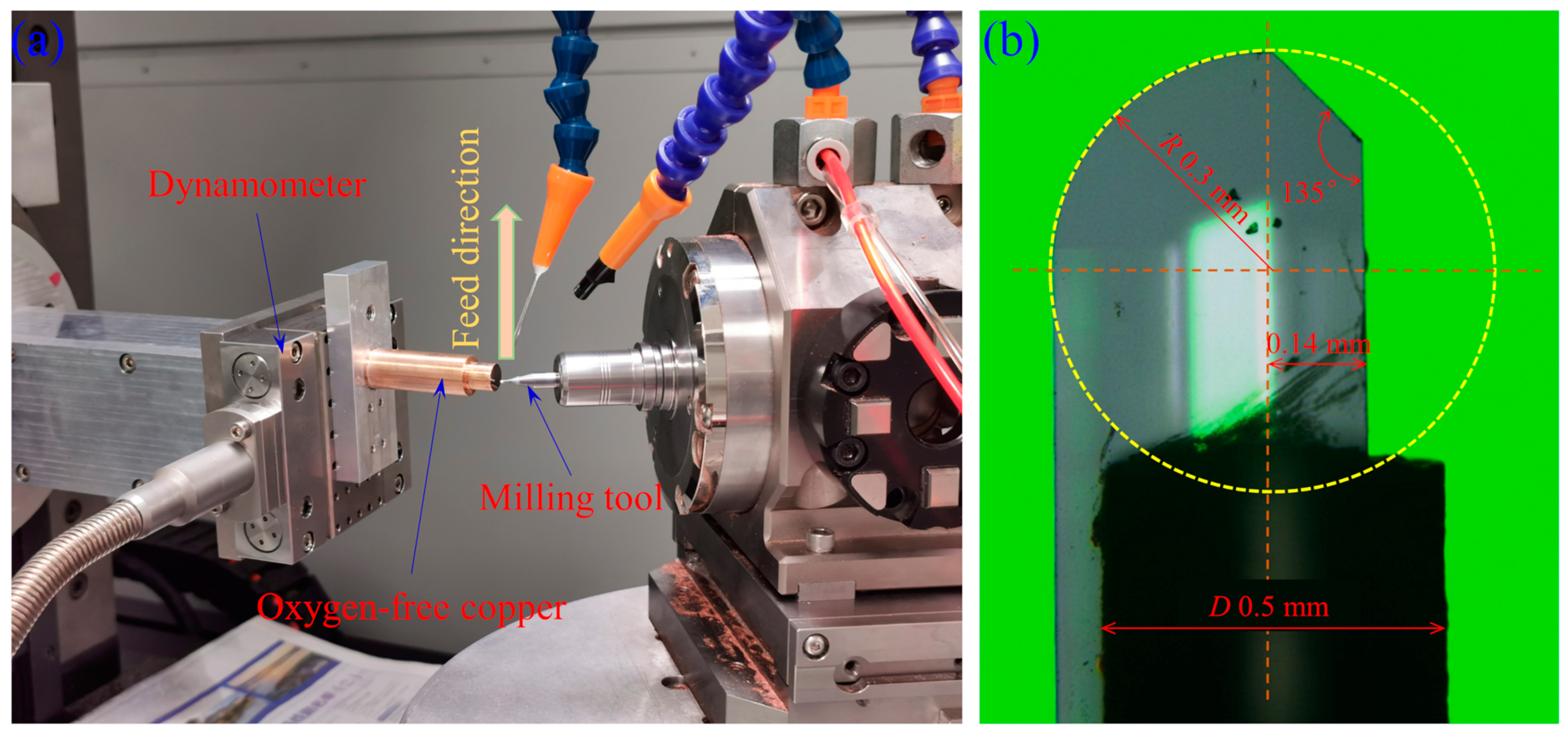
2. Experimental Setup of Diamond Micro-Milling

Figure 1a shows the configuration of a homemade five-axis linkage micro-milling lathe used in the micro-milling experiment, and the linear motion accuracy of the lathe is 5 nm. The Cu workpiece that is prepared by zone refining technology with a diameter of 10 mm is fixed by a planar fixture, which is then connected with the force dynamometer through threads. Specifically, the milling tool perpendicular to the workpiece surface is pre-deflected by 15° relative to a plane that coincides with the feed direction. The cutting force in the milling process is recorded with a three-component Kistler 9119AA1 dynamometer and a Kistler 5080A charge amplifier at a sampling rate of 10 kHz.
Figure 1b shows the optical image of the utilized single-edge diamond ball milling tool, which is composed of a carbide tool shank and a single-crystal diamond tool insert that are connected through brazing; the tool insert is prepared by the mechanical lapping of a natural diamond crystal. In particular, the rotation center of the tool shank coincides with the center of the ball head of the tool insert. The tool insert has a rake angle of 0°, a clearance angle of 7°, a nose radius of 0.3 mm and an edge radius of 80 nm. A white light interferometer (Zygo NewView 8200) is used to measure the roughness of the milled surface. Detailed parameters for the milling processes are listed in Table 1. In particular, the effect of the spindle speed ranging from 6000 to 30,000 rpm on the milling process is considered. Due to the low stiffness of the milling tool in micro-milling, the DOC is limited to 2 μm to ensure that the tool is not broken in the milling process.

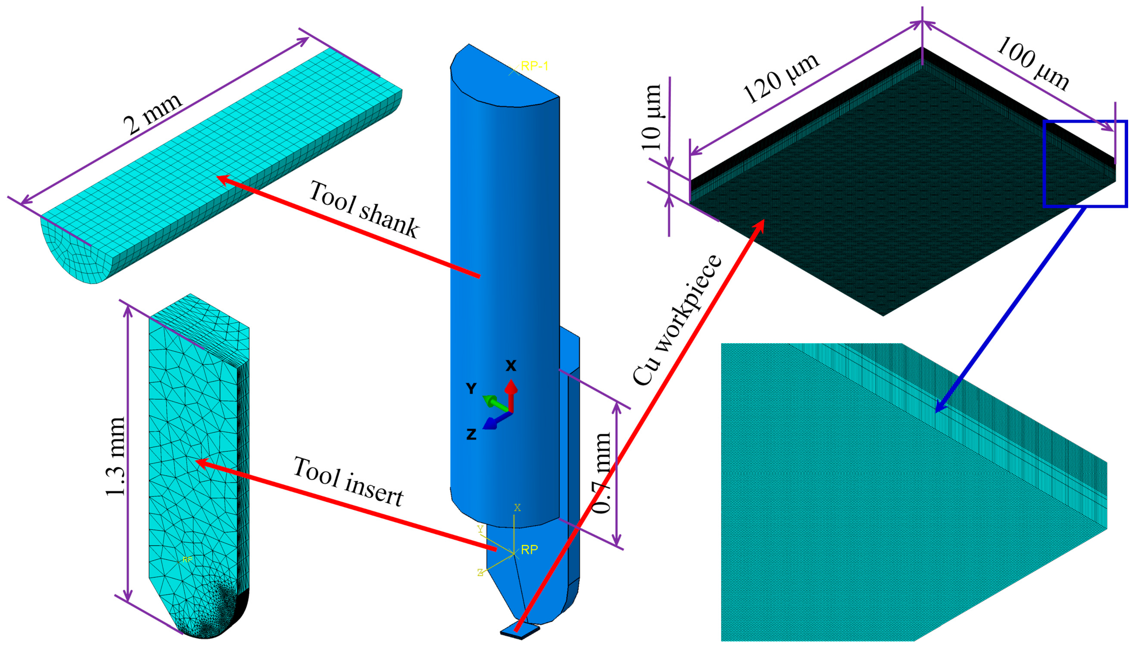
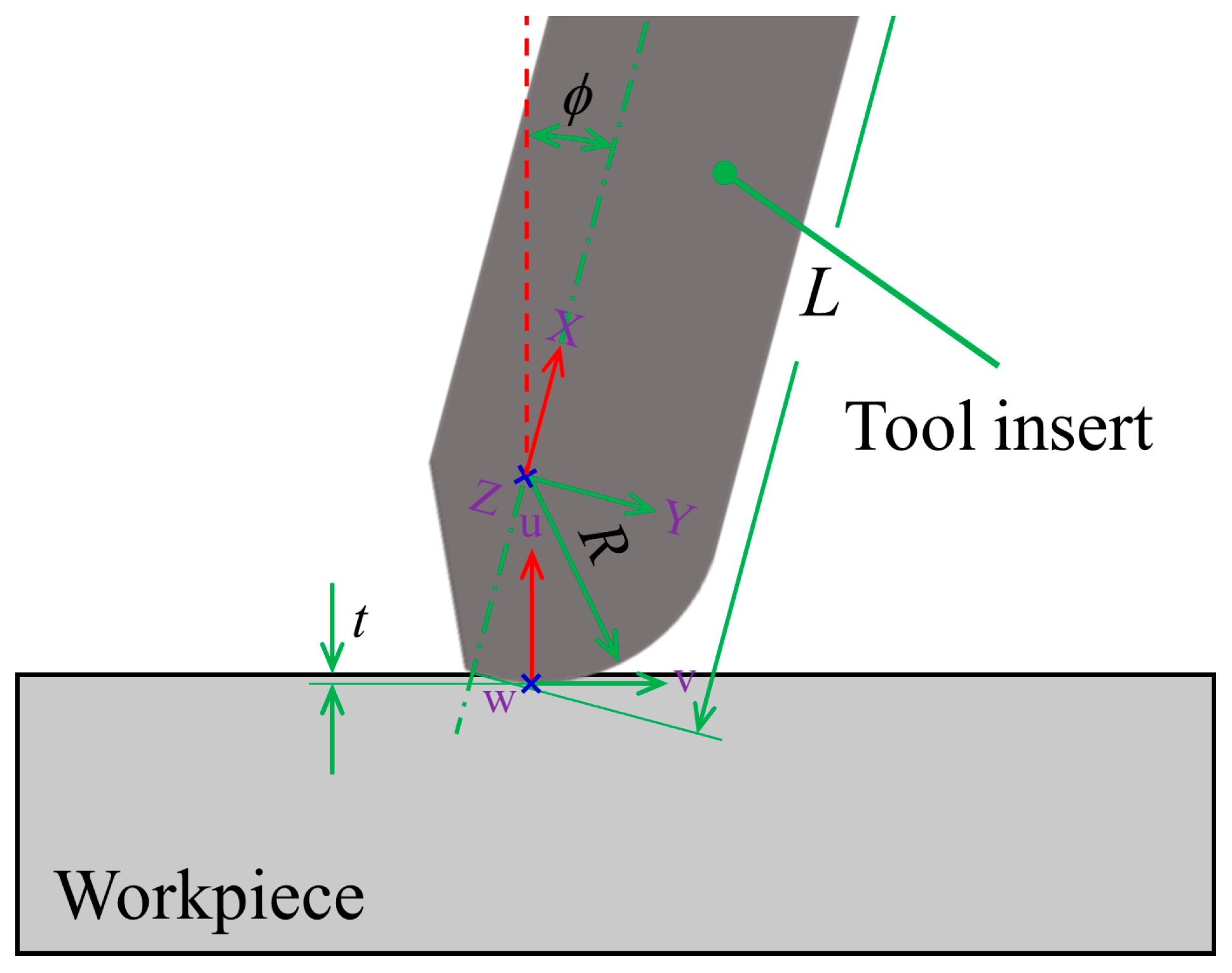
3. FE Modeling of the Diamond Micro-Milling of Cu

Figure 2 shows the FE model of micro-milling, which is composed of a Cu workpiece and a diamond milling tool. The workpiece has dimensions of 10 μm in height, 100 μm in width and 120 μm in length, and the bottom is constrained against any movement in each direction. Since the stiffness of diamond is much higher than that of cemented carbide, it is believed that the deformation of the tool shank is the main factor causing the tool chatter during the milling process. Consistent with the experimental configuration, the milling tool is composed of a deformable tool shank and a rigid diamond tool insert. The tool insert has a length of 1.3 mm, a clearance angle of 7° and an edge radius of 0 nm. The tool shank has a length of 2 mm, and the contact length between the tool shank and tool insert is 0.7 mm. The rotary axis of the diamond tool insert and the carbide tool shank both coincide with the X axis of the global XYZ coordinate system in the FE model. There is an inclination angle of 15° between the YZ plane of the workpiece surface and the milling tool. The coordinates on the rotary axis of the milling tool do not change during the FE simulation of the micro-milling process, so the center point of the tool ball head is treated as the output point to characterize the tool chatter during the micro-milling process, as shown in Figure 2a. The profile of the milled groove bottom is extracted from the bottom, where the tool insert contacts with the Cu workpiece along the feed direction.
In the as-established FE model of micro-milling, the upper half layer of the Cu workpiece with a thickness of 5 μm is meshed by eight-node linear hexahedron elements (C3D8) with a global size of 5 nm. A coarser mesh with a mesh size of 6–10 nm is used at the bottom of the Cu workpiece to improve computational efficiency, as shown in Figure 1. The interaction between the tool shank and tool insert is modeled by a tie constraint. Table 2 lists the mechanical properties of Cu [18], cemented carbide [19] and diamond [20]. The Cu workpiece is considered as isotropic material in the FE model, and the Johnson–Cook (J–C) constitutive model is used to characterize its elastoplastic deformation behavior:
σ ¯ = [ A + B ( ε ¯ p l ) n ] [ 1 + C ln ξ ˙ ] ( 1 θ ^ m )
where σ ¯ is the yield stress, ε ¯ p l is the equivalent plastic strain, ξ ˙ is the dimensionless plastic strain. A , B , n , m and θ ^ stand for the yield stress, strain hardening modulus, hardening index, thermal softening index and nondimensional temperature, respectively. In order to determine the thermal softening index m , the function f 3 ( T * ) is expressed as Equation (2):
f 3 ( T * ) = ( 1 θ ^ m ) = σ ¯ ( T * ) σ ¯ ( T )
where σ ¯ ( T * ) and σ ¯ ( T ) are the yield stress at the current temperature T * and the reference temperature T , respectively. Finally, the value of m is obtained by fitting f 3 ( T * ) .
Table 3 lists the corresponding parameters of the J–C constitutive model for Cu [18]. A global ductile J–C failure criterion (damage initiation criteria of the fracture of metals) based on a critical equivalent plastic strain ε ¯ D p l is adopted to simulate material separation and chip formation:
ε ¯ D p l = [ d 1 + d 2 exp ( d 3 η ) ] [ 1 + d 4 ln ( ε ¯ p l ε · 0 ) ] ( 1 + d 5 θ ^ )
where d 1 , d 2 , d 3 , d 4 and d 5 are failure parameters. Table 4 lists the specific parameters of the J–C damage criterion [18]. The FE model only considers the linear elastic behavior of deformable carbide shanks. The Coulombic friction coefficient, which is independent of the temperature and relative speed of motion between the milling tool and the Cu workpiece, is set as 0.396 [21].

4. Results and Discussion

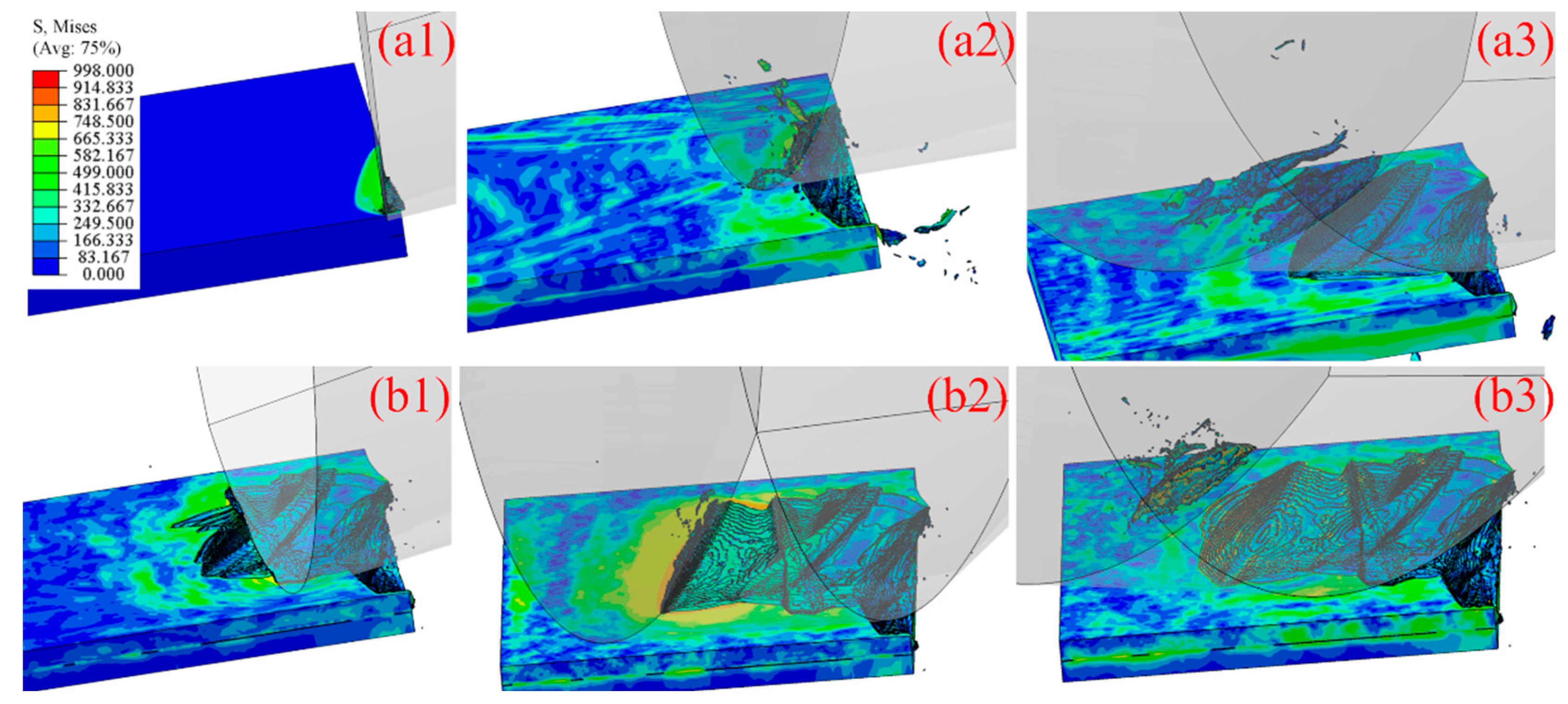
4.1. Relationship between Tool Chatter and Transient DOC in Micro-Milling

Figure 3 illustrates the impact of tool chatter on the transient DOC in micro-milling. The origin of the XYZ coordinate system coincides with the center of the tool ball head. Specifically, the tool deformation accompanied by tool chatter can be decomposed into the deflection around the top of the tool insert axis and the translation in space. It is assumed that the known positional translation of the center of the tool ball head in the X, Y and Z direction is Δ x , Δ y and Δ z , respectively. Therefore, the coordinate of the tool ball head center in the XYZ coordinate system before and after the milling tool deformation is (0, 0, 0) and ( Δ x , Δ y , Δ z ), respectively. As shown in Figure 3, a UVW coordinate system is set at the tangent point between the tool ball head and the machined surface. Therefore, the UVW coordinate system can be regarded as the translation of the XYZ coordinate system through a rotation by ϕ around the Z axis, which can be described by the vector of (−R, 0, 0). Then, the coordinates in the UVW coordinate system after the deformation of the center of the tool ball head can be expressed by Equations (4) and (5):
T = [ cos ϕ sin ϕ 1 0 sin ϕ cos ϕ 0 0 0 0 0 0 0 0 0 1 ] [ 1 0 0 R 0 1 0 0 0 0 1 0 0 0 0 1 ]
[ u v w 1 ] = T 1 [ Δ x Δ y Δ z 1 ]
where ϕ is the pre-deflection angle of the milling tool with respect to the workpiece surface, and T is the transformation matrix for transforming the XYZ coordinate system to the UVW coordinate system. Therefore, the transient DOC t 0 associated with the tool chatter in micro-milling can be expressed by Equation (6):
t 0 = t u

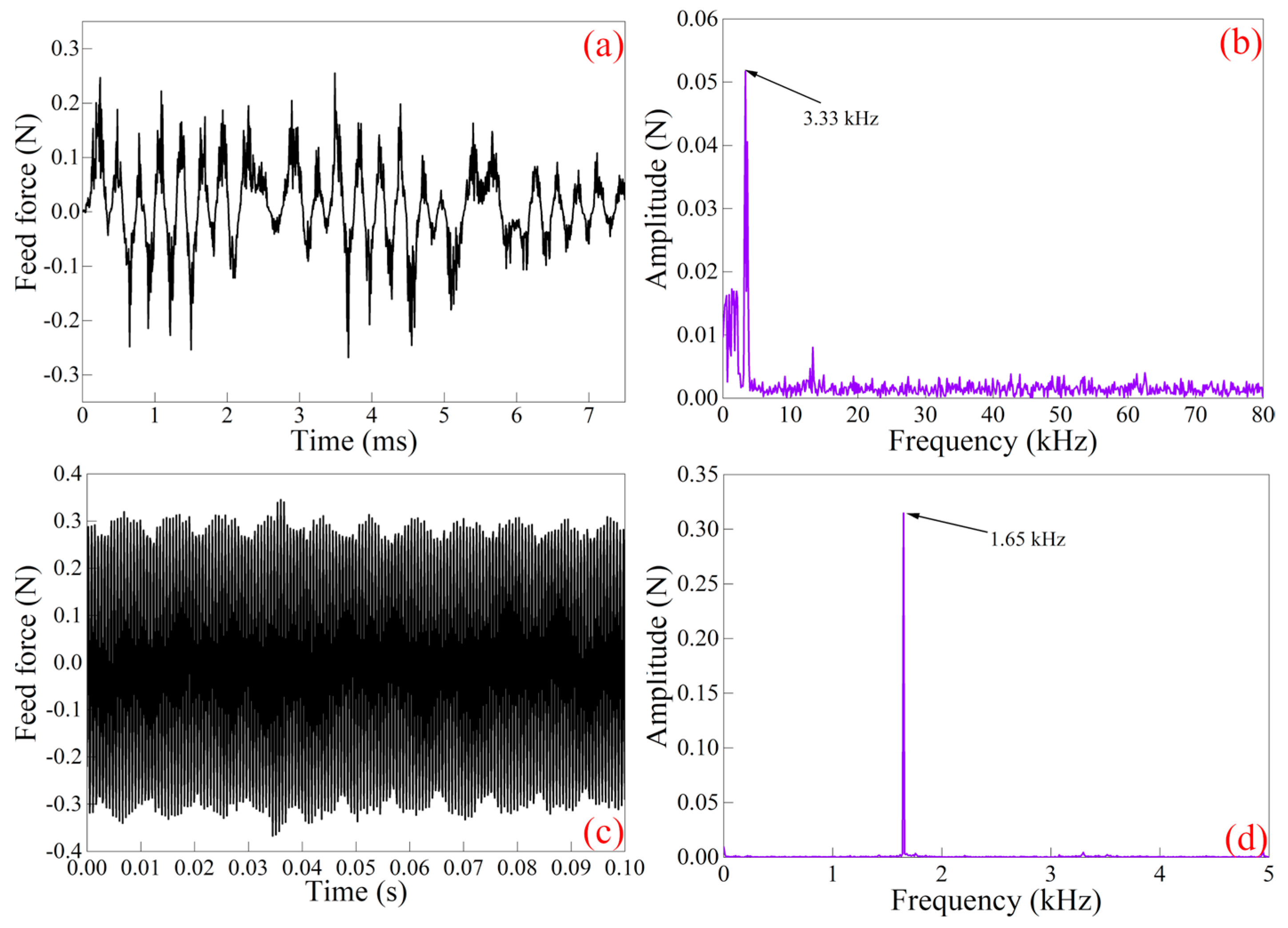
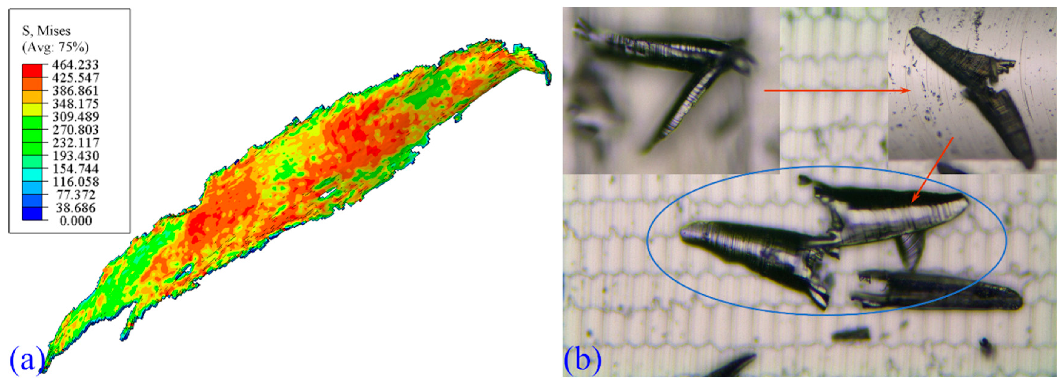
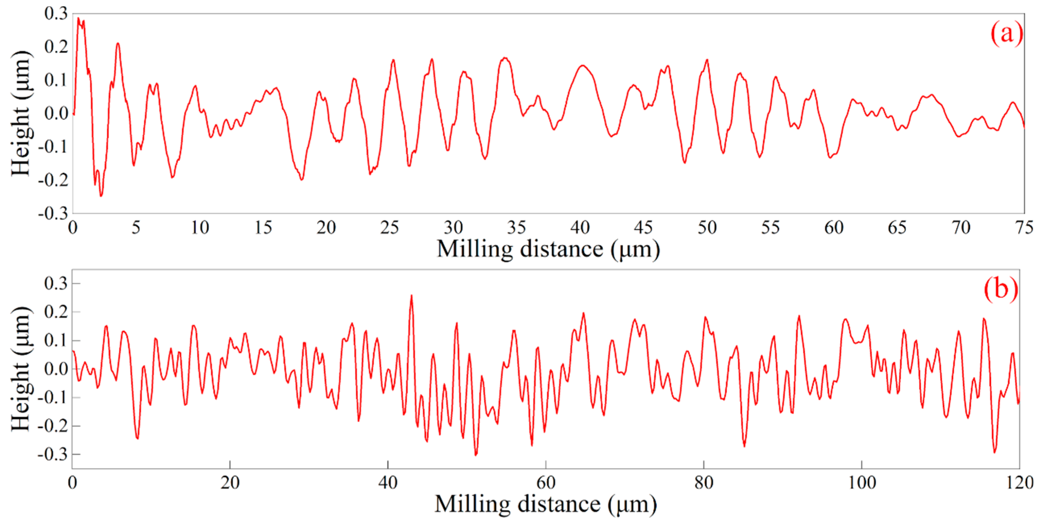
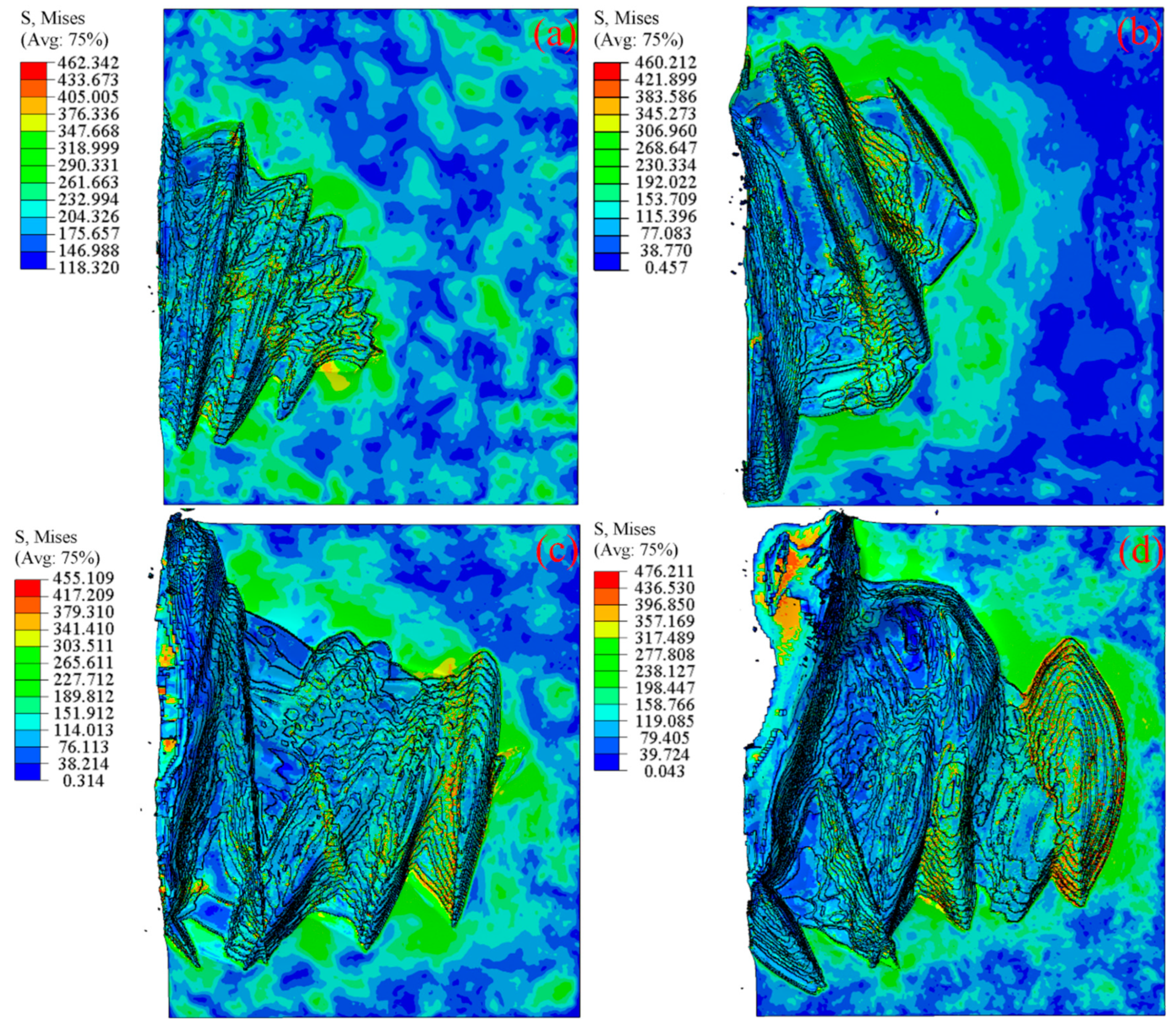
4.2. Tool Chatter Behavior in Micro-Milling

Experiments and corresponding FE simulations of micro-milling with a DOC of 2 μm, a spindle speed of 12,000 r/min and a feed speed of 10 mm/s are conducted to investigate the tool chatter behavior. The variation in the simulated feed force with time in the micro-milling of the Cu workpiece is shown in Figure 4, which demonstrates that the feed force is irregular fluctuations. Figure 4c plots the corresponding experimental feed force–time curve within a time of 0.1 s, which indicates that the feed force shows long-range periodicities. Figure 4a,c indicate that the fluctuations of the simulated feed force and the experimental feed force are both in the range of −0.3 to 0.3 N, which also demonstrates the high prediction accuracy of the established FE model of diamond micro-milling.
To reveal the intrinsic characteristics of tool chatter, Figure 4b,d present the amplitude-frequency of the simulated and experimental feed force by fast Fourier transform analysis (FFT), respectively. Figure 4b shows that the frequency of the simulated feed force is in the range of 0–80 kHz, with a peak at 3.33 kHz. Figure 4d indicates that the main frequency of the experimental feed force is 1.65 kHz, with a frequency range of 0–5 kHz. The differences in the fluctuation characteristics of the feed force between the FE simulation and experiment are mainly caused by the low sensitivity of the experimentally utilized dynamometer, which is insufficient to capture the tool chatter-induced feed force variations with a high frequency; similar conclusions have also been illustrated by Delio et al. [22].
Figure 5 shows the FE simulation results of the milling process for the first two rotation cycles considering tool chatter. As shown in Figure 5a1, in the initial stage of the milling process, contact stress originates in the local contact area between the milling tool edge and workpiece. The transient DOC is the theoretical maximum value accompanied by the largest amount of material removal at this point of the initial contact between the milling tool and workpiece; thus, the milling tool deformation is the largest in the thrust direction. As shown in Figure 5a2, the material removal volume increases gradually with the feed of the milling tool, and chips start to form and subsequently flow along the rake face of the milling tool. Accompanied by the increase in the deformation and chatter of the milling tool, the stress concentration in the workpiece is also increased. As shown in Figure 5a3, with the further feeding of the milling tool, the accumulated chips are curled, and the tool chatter accompanied by the tool deformation causes irregular fluctuations on the machined surface morphology.
Figure 5b1 shows the configuration of the milling tool cutting into the workpiece in the second rotation cycle in the milling process. The milling tool first contacts with both sides of the groove formed by the first rotation cycle, accompanied by stress concentrations formed on both sides. As shown in Figure 5b2, as the milling tool continues to feed, the material removal gradually increases, and chips are gradually formed after the tool cuts through the groove formed by the first rotation cycle. The machined surface morphology shown in Figure 5b3 demonstrates that the transient DOC has an increasing trend at first but then decreases when it reaches a critical value, at which point the milling tool rebounds sharply due to the increased extrusion effect of the workpiece on the milling tool, resulting in a steep groove at the end of milling.
Figure 6a,b show a chip profile obtained in the FE simulation and the experiment of diamond micro-milling of the Cu workpiece, respectively. Both the simulated and experimental chips have the characteristics of long strips with narrow end regions and wide middle regions. Specifically, a broken chip from the middle is also observed in the experiment. The stress distribution in the middle of the simulated chip is less pronounced than that at the two sides, which leads to the broken chip observed in the experiment.
The simulated profile of the groove bottom is obtained by substituting the tool deformation extracted in Figure 3a into Equations (3)–(5). Figure 7a,b present the profile of the milling groove bottom from the FE simulation and the experiment of Cu micro-milling of the Cu workpiece, respectively. It is seen from Figure 7 that the groove bottom profile shows up- and down-fluctuations caused by the tool chatter, and the microscopic roughnesses Rz of the machined surface by both the FE simulation and experiment have a high consistency with each other in the range between 0.4 μm and 0.5 μm, which further demonstrates that the established FE model of micro-milling is capable of predicting the profile accuracy of a machined surface with high accuracy. It is worth noting that the machined surface profile by the experiment has more severe fluctuations than that by the simulation, which may be due to the fact that the simulation does not consider the crystal anisotropy, which may result in the formation of grain boundary steps on the machined surface in the experiment. Therefore, the superposition of grain boundary steps and tool chatter accounts for the dramatic fluctuations in the machined surface profile observed in the micro-milling experiments.

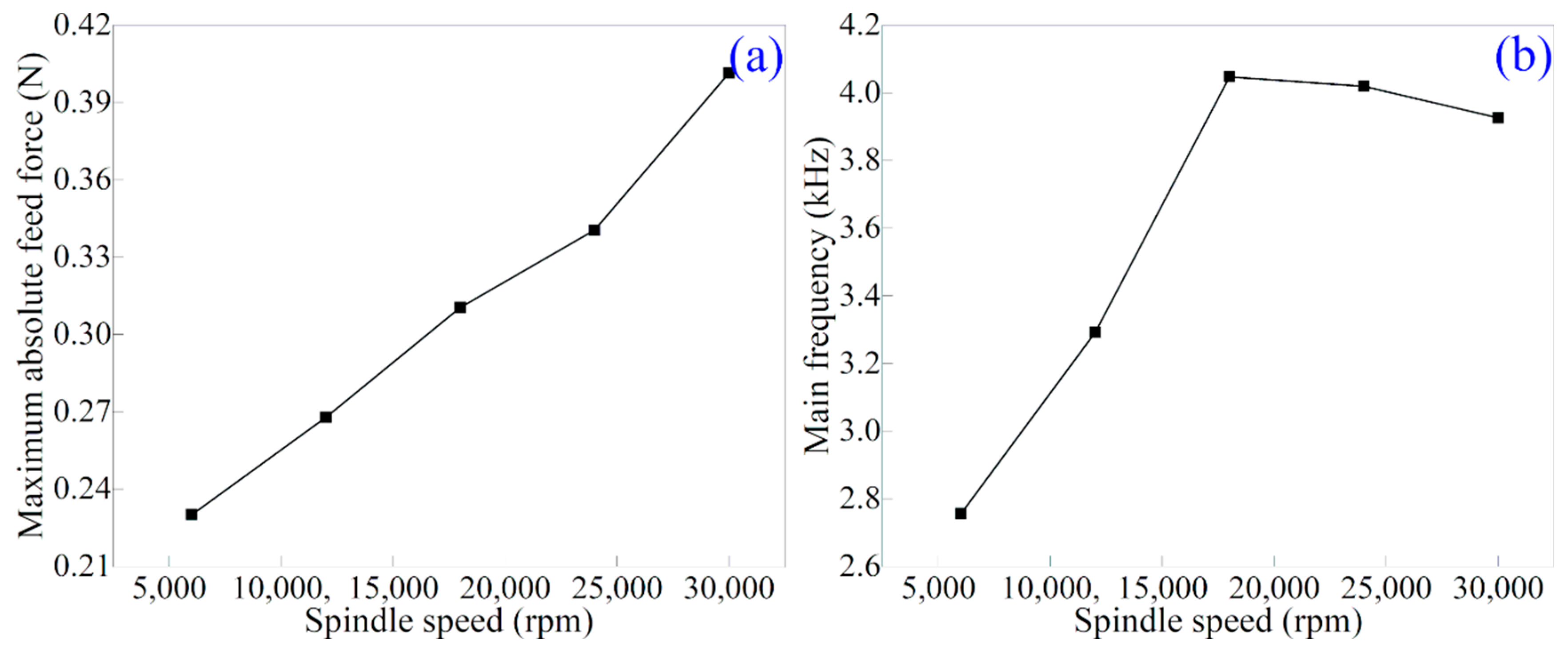
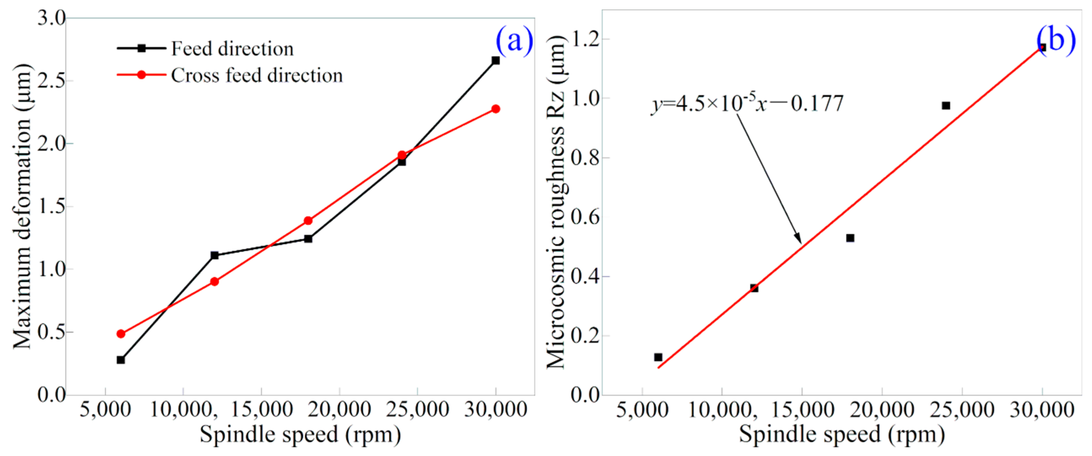
4.3. Effect of Spindle Speed on Tool Chatter

While the above section demonstrates the prediction accuracy of the established FE model, subsequent FE simulations of diamond micro-milling of the Cu workpiece with different spindle speeds are performed to investigate the effect of spindle speed on the tool chatter behavior. Figure 8a,b present the simulated results of the maximum absolute feed force and the main frequency of feed force for spindle speeds ranging from 6000 rpm to 30,000 rpm, respectively. Figure 8 demonstrates that the maximum absolute feed force increases with the increase in spindle speed, indicating the increase in milling tool deformation with spindle speed. However, the main frequency of the feed force first increases with the increase in spindle speed and reaches the maximum at the spindle speed of 18,000 rpm, but it then decreases slightly with the further increase in the spindle speed.
Figure 9 presents the morphologies of the machined surface under different spindle speeds by FE simulations. It can be clearly observed from Figure 9 that the damage at the workpiece edge increases with spindle speed, which is consistent with the maximum deformation of the milling tool. Therefore, it indicates that the milling tool deformation is closely associated with the workpiece edge failure. Figure 9 also indicates that the distance between the discontinuous pits remaining on the machined surface caused by tool chatter is gradually increasing with spindle speed, which indicates that the frequency of tool chatter decreases with the increase in spindle speed.
Figure 10a,b present the simulated results of the maximum deformation of the milling tool and the microscopic roughness Rz of the machined surface for spindle speeds ranging from 6000 rpm to 30,000 rpm, respectively. Figure 10a shows that, with the increase in spindle speed, the maximum deformations of the milling tool in both the feed direction and the cross-feed direction increase and are substantially equal to each other. Figure 10b demonstrates that, with the increase in spindle speed, the microscopic roughness Rz of the machined surface also increases, which follows a linear relationship. Specifically, the relationship between the spindle speed and the microscopic roughness of the machined surface is fitted as y = 4.5 × 10 5 x 0.177 , where y is the microscopic roughness of the machining surface Rz (μm) and x is the milling spindle speed (rpm).

5. Conclusions

In summary, we perform an analytical investigation, FE simulations and experiments to investigate the tool chatter in the diamond micro-milling of the Cu workpiece. Specifically, the analytical correlation of tool chatter in the milling process indicates that the transient DOC changes significantly with tool deformation, leading to a strongly varied morphology of the groove bottom. FE simulations and experiments both reveal that the tool chatter leads to dramatic changes in milling force and tool deformation, and the predicted morphology of the groove bottom by the FE simulation is consistent with the experimental one, with a deviation of less than 50 nm. It is also found that there is a linear relationship between the spindle speed and microscopic roughness Rz of the machined surface. This research provides a theoretical basis for understanding the tool chatter in the diamond micro-milling process of the planar surface. When a curved surface is processed, the theory in Section 4.1 will become more complicated, which needs future investigation.

Author Contributions

Conceptualization, H.Z. and J.Z.; methodology, J.Z.; software, S.L. and F.T.; validation, C.Z. and G.L.; resources, H.Z., G.L. and J.Z.; writing—original draft preparation, S.L.; writing—review and editing, J.Z. and H.Z.; visualization, S.L. and F.T.; supervision, J.Z. and T.S.; project administration, J.Z. and H.Z.; funding acquisition, J.Z. and H.Z. All authors have read and agreed to the published version of the manuscript.

Funding

This research was funded by Science Challenge Project (No. TZ2018006-0201-02 and TZ2018006-0205-02).

Conflicts of Interest

The authors declare no conflict of interest.

References

  1. Lan, K.; Liu, J.; Lai, D.; Zheng, W.; He, X.-T. High flux symmetry of the spherical hohlraum with octahedral 6LEHs at the hohlraum-to-capsule radius ratio of 5.14. Phys. Plasmas 2014, 21, 010704. [Google Scholar] [CrossRef] [Green Version]
  2. Li, X.; Wu, C.; Dai, Z.; Zheng, W.; Zhao, Y.; Zhang, H.; Gu, J.; Kang, D.; Ge, F.; Gu, P.; et al. Review of the three candidate hohlraums in ICF. arXiv 2016, arXiv:1608.02167. [Google Scholar]
  3. Lan, K.; He, X.-T.; Liu, J.; Zheng, W.; Lai, D. Octahedral spherical hohlraum and its laser arrangement for inertial fusion. Phys. Plasmas 2014, 21, 052704. [Google Scholar] [CrossRef]
  4. Du, K.; Liu, M.; Wang, T.; He, X.; Wang, Z.; Zhang, J. Recent progress in ICF target fabrication at RCLF. Matter Radiat. Extremes 2018, 3, 135–144. [Google Scholar] [CrossRef] [Green Version]
  5. Montesanti, R.C.; Seugling, R.M.; Klingmann, J.L.; Dzenitis, E.G.; Alger, E.T.; Miller, G.L.; Kent, R.A.; Castro, C.; Reynolds, J.L.; Carrillo, M.A. Robotic System for Precision Assembly of NIF Ignition Targets; Lawrence Livermore National Lab. (LLNL): Livermore, CA, USA, 2008.
  6. Afazov, S.M.; Ratchev, S.M.; Segal, J.; Popov, A.A. Chatter modelling in micro-milling by considering process nonlinearities. Int. J. Mach. Tools Manuf. 2012, 56, 28–38. [Google Scholar] [CrossRef] [Green Version]
  7. Yue, C.; Gao, H.; Liu, X.; Liang, S.Y.; Wang, L. A review of chatter vibration research in milling. Chin. J. Aeronaut. 2019, 32, 215–242. [Google Scholar] [CrossRef]
  8. Liu, X.; Gao, H.; Yue, C.; Li, R.; Jiang, N.; Yang, L. Investigation of the milling stability based on modified variable cutting force coefficients. Int. J. Adv. Manuf. Technol. 2018, 96, 2991–3002. [Google Scholar] [CrossRef]
  9. Ji, Y.; Wang, X.; Liu, Z.; Yan, Z.; Jiao, L.; Wang, D.; Wang, J. EEMD-based online milling chatter detection by fractal dimension and power spectral entropy. Int. J. Adv. Manuf. Technol. 2017, 92, 1185–1200. [Google Scholar] [CrossRef]
  10. Moradi, H.; Vossoughi, G.; Behzad, M.; Movahhedy, M.R. Vibration absorber design to suppress regenerative chatter in nonlinear milling process: Application for machining of cantilever plates. Appl. Math. Model. 2015, 39, 600–620. [Google Scholar] [CrossRef]
  11. Tehranizadeh, F.; Koca, R.; Budak, E. Investigating effects of serration geometry on milling forces and chatter stability for their optimal selection. Int. J. Mach. Tools Manuf. 2019, 144, 103425. [Google Scholar] [CrossRef]
  12. Pérez-Canales, D.; Vela-Martínez, L.; Jáuregui-Correa, J.C.; Alvarez-Ramirez, J. Analysis of the entropy randomness index for machining chatter detection. Int. J. Mach. Tools Manuf. 2012, 62, 39–45. [Google Scholar] [CrossRef]
  13. Li, X.Q.; Wong, Y.S.; Nee, A.Y.C. Tool wear and chatter detection using the coherence function of two crossed accelerations. Int. J. Mach. Tools Manuf. 1997, 37, 425–435. [Google Scholar] [CrossRef]
  14. Tripathi, A.; Das, P.; Aggarwal, T. Diminution of chatter vibration in single point cutting tool holder using finite element analysis (FEA). Mater. Today Proc. 2022, 62, 3665–3669. [Google Scholar] [CrossRef]
  15. Mahnama, M.; Movahhedy, M.R. Prediction of machining chatter based on FEM simulation of chip formation under dynamic conditions. Int. J. Mach. Tools Manuf. 2010, 50, 611–620. [Google Scholar] [CrossRef]
  16. Jafarzadeh, E.; Movahhedy, M.R.; Khodaygan, S.; Ghorbani, M. Prediction of machining chatter in milling based on dynamic FEM simulations of chip formation. Adv. Manuf. 2018, 6, 334–344. [Google Scholar] [CrossRef]
  17. Suzuki, N.; Takahashi, W.; Igeta, H.; Nakanomiya, T. Flank face texture design to suppress chatter vibration in cutting. CIRP Ann. 2020, 69, 93–96. [Google Scholar] [CrossRef]
  18. Johnson, G.R.; Cook, W.H. Fracture characteristics of three metals subjected to various strains, strain rates, temperatures and pressures. Eng. Fract. Mech. 1985, 21, 31–48. [Google Scholar] [CrossRef]
  19. Wang, Y.; Su, H.; Dai, J.; Yang, S. A novel finite element method for the wear analysis of cemented carbide tool during high speed cutting Ti6Al4V process. Int. J. Adv. Manuf. Technol. 2019, 103, 2795–2807. [Google Scholar] [CrossRef]
  20. Zong, W.J.; Li, Z.Q.; Zhang, L.; Liang, Y.C.; Sun, T.; An, C.H.; Zhang, J.F.; Zhou, L.; Wang, J. Finite element simulation of diamond tool geometries affecting the 3D surface topography in fly cutting of KDP crystals. Int. J. Adv. Manuf. Technol. 2013, 68, 1927–1936. [Google Scholar] [CrossRef]
  21. Liu, S.; Zhang, H.; Zhao, L.; Li, G.; Zhang, C.; Zhang, Z.; Sun, T. Coupled thermo-mechanical sticking-sliding friction model along tool-chip interface in diamond cutting of copper. J. Manuf. Process. 2021, 70, 578–592. [Google Scholar] [CrossRef]
  22. Delio, T.; Tlusty, J.; Smith, S.M. Use of audio signals for chatter detection and control. J. Manuf. Sci. Eng. 1992, 114, 146–157. [Google Scholar] [CrossRef]
Figure 1. (a) Experimental layout of diamond micro-milling; (b) Optical image of the single-edge diamond ball milling tool.
Applsci 12 11968 g001
Figure 2. FE model of the micro-milling of Cu considering milling tool deformation.
Applsci 12 11968 g002
Figure 3. Schematic illustration of the tool chatter impact on the transient DOC in micro-milling.
Applsci 12 11968 g003
Figure 4. Variation in feed force with time in (a) FE and (c) experiment simulation of micro-milling; FFT analysis of feed force in (b) FE simulation and (d) experiment.
Applsci 12 11968 g004
Figure 5. FE simulation of the chip formation process during diamond milling in the (top) first and (bottom) second rotation cycle. (a1) and (b1) Initial tool-workpiece contact, (a2) and (b2) Generation of chips, and (a3) and (b3) Tool-chip separation.
Applsci 12 11968 g005
Figure 6. Chip profile obtained in the diamond micro milling process of the Cu workpiece by the (a) FE simulation and (b) experiment.
Applsci 12 11968 g006
Figure 7. Groove bottom profile by the (a) FE simulation and (b) experiment of diamond micro-milling of the Cu workpiece.
Applsci 12 11968 g007
Figure 8. FE simulation results of the effect of spindle speed on (a) the maximum absolute feed force and (b) the main frequency of feed force.
Applsci 12 11968 g008
Figure 9. FE simulation results of machined surface morphologies under different spindle speeds: (a) 6000 rpm, (b) 18,000 rpm, (c) 24,000 rpm and (d) 30,000 rpm.
Applsci 12 11968 g009
Figure 10. FE simulation results of the effect of spindle speed on (a) the maximum deformation of the milling tool and (b) the microscopic roughness Rz of the machined surface.
Applsci 12 11968 g010
Table 1. Parameters of micro-milling.
ParametersUnitValues
Feed speedmm/s10
Spindle speedrpm6000, 12,000, 18,000, 20,000, 30,000
DOCμm2
Table 2. Physical parameters of Cu [18], cemented carbide [19] and diamond [20].
Material PropertiesUnitCuCemented CarbideDiamond
Thermal conductivityW/(mm*k)386902000
DensityKg/m3896014,5004250
Elastic modulusGPa1245801147
Poisson ratio0.340.220.07
Specific heat capacityJ/(Kg*K)383220502
Thermal expansion coefficientK−15 × 10−55.4 × 10−61.18 × 10⁻⁶
Table 3. Parameters of the J–C constitutive law for the Cu workpiece used in the FE model [18].
A(MPa)B(MPa)nCm
902920.310.0251.09
Table 4. Parameters of the J–C failure criterion algorithm for the Cu workpiece used in the FE model [18].
d 1 d 2 d 3 d 4 d 5
0.544.89−3.030.0141.12
Publisher’s Note: MDPI stays neutral with regard to jurisdictional claims in published maps and institutional affiliations.

