Article

Analytical Calculation of Air-Gap Magnetic Field Distribution in IPMSMs with Mixed Eccentricity Accounting for Bridge Saturation

1
School of Science, Xi’an University of Architecture and Technology, Xi’an 710055, China
2
School of Mechanical and Electrical Engineering, Xi’an University of Architecture and Technology, Xi’an 710055, China
3
Shenzhen Academy of Robotics, Shenzhen 518057, China
*
Author to whom correspondence should be addressed.
Appl. Sci. 2022, 12(23), 11956; https://doi.org/10.3390/app122311956
Submission received: 7 November 2022 / Revised: 21 November 2022 / Accepted: 22 November 2022 / Published: 23 November 2022
(This article belongs to the Topic Advanced Electrical Machines and Drives Technologies)

Abstract

:
This paper presents an analytical model for calculating the detailed air-gap magnetic field distribution in interior permanent magnet synchronous motors (IPMSMs) with mixed eccentricity. In order to improve the efficiency of model solving, a modeling strategy combining the equivalent magnetic circuit network method and the subdomain method was adopted. Specifically, the magnetic field distribution of the rotor was modeled by using the magnetic circuit analysis method, and the magnetic field distributions of the air-gap, slot opening and stator slot along the radial direction were modeled in different regions according to their structure ruler. Then, the influence of bridge saturation was considered. Moreover, based on the analysis of the air-gap geometric structure with mixed eccentricity, a detailed spatiotemporal analytical model of the air-gap magnetic field was established, which provides a more accurate description of the mixed eccentricity composed of static and dynamic rotor eccentricities of different severity. The analytical models were compared with the corresponding models established by the finite element method, which proved the accuracy and validity of the models established in this paper. Finally, some key features related to radial and tangential air-gap flux density were extracted, which can significantly reflect the characteristics of eccentricities. The main findings reported in this paper will be of benefit for developing methods for early identification and diagnosis of eccentricity faults in IPMSMs.

1. Introduction

Recently, interior permanent magnet synchronous motors (IPMSMs) have been widely used in electric vehicles and other industrial fields due to their characteristics of high efficiency, high power density, carbon free and zero emission [1,2,3,4]. As a result, the requirements for safe and healthy operation with high performance are becoming higher and higher. In actual application, due to the manufacturing, installation and variation in support stiffness, rotor mixed eccentricity is a widespread phenomenon in the operation of the IPMSM, which leads to the distortion of the air-gap magnetic field of the motor and affects the performance and efficiency of the motor, and even affects the service life of the motor [5]. Therefore, it is important to clarify the variation rule and characteristics of the air-gap magnetic field in IPMSMs with mixed eccentricity, so as to further realize the early diagnosis of mixed eccentricity faults and the real-time control, which is of great significance for the healthy and efficient operation of the motor [5,6,7].
In order to build the model of air-gap magnetic field, two types of methods are usually used: finite element methods and analytical methods. The finite element method is a relatively mature method for numerical modeling. Through the refined solid models and the configuration of constraints, the air-gap magnetic field can be accurately calculated under different operation conditions. However, the real-time performance is not good, and the consumption of computing resources is large. Therefore, it has been mostly used in the design optimization and structural verification of the motor [8,9]. In contrast, the analytical methods can reveal the coupling law between mechanical/electrical parameters and magnetic field through mathematical modeling, the motor and has a fast running speed [3,10]. Therefore, analytical method has been widely used in the research of motor fault diagnosis mechanisms. However, there are many factors affecting the spatial and temporal distribution of the air-gap magnetic field in IPMSMs. The main factors include the load characteristics, the cogging effect formed between the permanent magnet and stator teeth, and the magnetic saturation in the bridge region. In addition, in the study of the air-gap magnetic field under rotor eccentricity, single static eccentricity, or dynamic eccentricity, has been considered in previous research [11,12,13], which is different from the mixed eccentricity in actual operation. Therefore, the establishment of the analytical model of air-gap magnetic field accounts for the above factors is a key issue to accurately calculate the spatial and temporal distribution of the air-gap magnetic field under the general operation of IPMSMs.
At present, the analytical methods for modeling the air-gap magnetic field of permanent magnet synchronous motors (PMSMs) include the equivalent magnetic circuit network method [14,15,16,17], the subdomain model method [18,19,20,21], and the magneto-motive force-magnetic permeability method [22,23,24,25,26]. In [14,15], the equivalent magnetic circuit network method was used to model and analyze the rotor magnetic field of PMSM to verify the effect of the optimal design. The same method was used to model the armature magnetic field of the permanent magnet linear synchronous motor analytically in [16]. By combining the equivalent magnetic circuit network method and the Carter coefficient method, the influence of the cogging torque on the distribution of the air-gap magnetic field in the IPMSM was analyzed in [17]. However, the equivalent magnetic circuit network method can only calculate the radial component of the air-gap magnetic field and cannot calculate the tangential component of the air-gap magnetic field. What is more, the sub-circuit division needs to be more detailed in order to improve the calculation accuracy, and the amount of computation would be greatly increased [17]. For the subdomain modeling method, this was adopted to model the rotor magnetic field under no-load and under-load conditions in [18], in which the effect of saturation in iron core was taken into account. In [19], the subdomain model method was used to analyze the air-gap magnetic fields of the permanent magnet motor under no-load and load conditions. In this study, in order to calculate the influence of the saturation effect of the rotor iron core, the saturation effect is equivalent to the sector-shaped saturation region. In [20], the subdomain modeling method was used to analyze the distribution of the air-gap magnetic field of surface-mounted permanent magnet synchronous motors with different slot structures. In [21], the subdomain modeling method was used to model the armature reaction magnetic field of the PMSM, and the inductance parameters were identified. In this study, the effect of saturation in iron core was ignored. For the subdomain method, the mutual influence of the slots can be considered, but it is required to solve the partial differential equation and solve the undetermined coefficient through boundary conditions, which lead to a large amount of calculation. The most important thing for the subdomain method is that the effect of saturation in iron core on the air-gap magnetic field of the motor cannot be calculated directly. The magneto-motive force-magnetic permeability method [22,23,24,25,26] generally assumes that the magnetic permeability of the rotor core is infinite, so the nonlinear effect of saturation in the iron core on the air-gap magnetic field cannot be considered. At the same time, although the spatial distribution of the armature reaction magnetic field can be calculated by vector superposition, the effect of magnetic saturation is ignored [27,28]. We can conclude from the above analysis that, in the analytical modeling of air-gap magnetic field of the PMSM, a high-dimensional model and complex boundary conditions will be introduced due to the magnetic saturation in iron core. As a result, the influence of magnetic saturation in iron core has been ignored in the single analytical modeling method, which makes it difficult to accurately reflect the magnetic field distribution.
In view of the existing problems in the current analytical methods and in order to accurately calculate the air-gap magnetic field distribution in IPMSMs with mixed eccentricity, an analytical model that accounts for the influence of magnetic saturation in the bridge regions was established by combining the equivalent magnetic circuit network method and the subdomain method. This analytical model shows high accuracy, which has been verified by finite element simulation. Then, using the established model, the distribution of the air-gap magnetic field of the IPMSM with mixed eccentricity values of different severity was calculated, and features reflecting the eccentricity were extracted. The results of this study lay a foundation for developing early identification and diagnosis methods for eccentricity faults in IPMSMs.

2. Methods

The analytical model of air-gap magnetic field distribution in the IPMSM with mixed eccentricity can be established based on the normal model whose air-gap length is replaced by the air-gap geometric model with mixed eccentricity. In this section, the analytical model of the air-gap magnetic field in the IPMSM is established with the following assumptions: (1) The end effect, the rotor core conductivity and the eddy current effect are ignored. (2) The magnetic permeability of the rest of the iron core is infinite except for magnetic saturation in the bridge. (3) The stator slots and slot openings are approximately fan-shaped. The normal air-gap magnetic field considering bridge saturation is composed of the no-loaded air-gap magnetic field of the permanent magnet, the armature reaction air-gap magnetic field and the equivalent magnetic field of the effect of bridge saturation. During the establishment of each magnetic field model, the motor is divided into four subdomains along the radial direction: rotor, air-gap, slot opening and stator slot. The air-gap flux density contains temporal and spatial variables and is described with a radial component and a tangential component. The analytical method for efficient calculation of air-gap magnetic field is formed by combining the equivalent magnetic circuit network method and the subdomain method.

2.1. Analytical Model of the Normal Air-Gap Magnetic Field

2.1.1. Model of the Equivalent Magnetic Circuit of the Rotor

The flux is produced by the scalar magnetic potential on the rotor surface, and the part entering the air-gap is solved by using the equivalent magnetic circuit network method. The equivalent magnetic circuit is shown in Figure 1.
The permanent magnet magnetomotive force FM, equivalent reluctance RM, extreme flux leakage Φb and interpolar flux leakage Φi can be expressed by the motor parameters as
F M = B M h M μ 0 μ r
R M = h M μ 0 μ r L M L Z
Φ b = B s h b L Z
Φ i = B s h i 2 L Z
where BM is the residual magnetic induction intensity of the permanent magnet, hM is the thickness of the permanent magnet, μ0 is the vacuum permeability, μr is the relative permeability of the permanent magnet, LM is the width of the permanent magnet, LZ is the axial length of the iron core, BS is the magnetic induction intensity of bridge saturation, hb is the thickness of the end of bridge, and hi is the thickness of the interpolar magnetic in the bridge. The scalar magnetic potential of the rotor surface can be expressed as
Ω r = F M ( Φ b + Φ i + Φ g r ) R M
where Φgr is the magnetic flux entering the air-gap. It can be calculated as
Φ g r = F M R M Ω r R M Φ b Φ i

2.1.2. Model of the Air-Gap Magnetic Field of Permanent Magnet under No-Load

According to the assumptions, when the stator winding is an open circuit, the vector magnetic potential of each subdomain satisfies the Laplace Equation [1]:
2 φ r 2 + 1 r φ r + 1 r 2 2 φ α 2 = 0
The general solution of vector magnetic potential in air-gap is
A g p = k = 1 A g p k ( r R s ) k + B g p k ( r R s ) k cos ( k α ) + k = 1 C g p k ( r R s ) k + D g p k ( r R s ) k sin ( k α )
where Agp is the vector magnetic potential of the permanent magnet with no-load, and Agpk, Bgpk, Cgpk and Dgpk are the Fourier series undetermined coefficients of the air-gap magnetic field of the permanent magnet, RS is the inner radius of the stator, k is the harmonic order of the air-gap magnetic field, α is the circumferential angle of the air-gap space, and r is the length from the center of the radial rotor to the inner boundary of the stator.
Then, the radial component and tangential component of the flux density are described by Equation (9) and Equation (10), respectively
B r = 1 r A g p α
B t = A g p r
by substituting Equation (8) into Equations (9) and (10)
B r p g = k = 1 k r A g p k ( r R s ) k + B g p k ( r R s ) k cos ( k α ) + k = 1 k r C g p k ( r R s ) k + D g p k ( r R s ) k sin ( k α )
B t p g = k = 1 k r A g p k ( r R s ) k B g p k ( r R s ) k cos ( k α ) k = 1 k r C g p k ( r R s ) k D g p k ( r R s ) k sin ( k α )
where Brpg and Btpg are the radial and tangential components of air-gap flux density of permanent magnet with no-load, respectively, and k is the harmonic frequency of air-gap flux density.
The Fourier undetermined coefficients can be solved by the interface conditions of each subdomain of the IPMSM under no-load conditions. The interface conditions of each subdomain satisfy the conditions that: the vector magnetic potential and tangential flux density are both continuous on the interface between the stator slot and slot opening; the vector magnetic potential and tangential flux density are also continuous on the interface between the slot opening and air-gap; the scalar magnetic potential and air-gap magnetic flux are continuous on the interface between rotor and air-gap. According to the above interface conditions, the constraint Equations of the undetermined coefficients can be derived as
0 0 0 K 14 K 15 K 16 K 17 K 18 0 K 22 K 23 0 0 K 26 K 27 0 0 K 32 K 33 K 34 K 35 K 36 K 37 0 0 0 0 K 44 K 45 0 0 K 48 0 0 0 0 0 K 56 K 57 K 58 K 61 K 62 K 63 0 0 0 0 0 0 K 72 K 73 K 74 K 75 0 0 0 K 81 K 82 K 83 0 0 0 0 0 Ω r A g p k B g p k C g p k D g p k A s o p i B s o p i A s p i = Y 0 0 0 0 0 0 0
where K11~K88 are the coefficient matrixes under each boundary condition, respectively, which depend on the motor structure parameters, and Y is determined by the rotor magnetic field. Agpk, Bgpk, Cgpk and Dgpk are the undetermined coefficients of Fourier series of air-gap flux density general solution, respectively. Asopi and Bsopi are the undetermined coefficients of flux density Fourier general solution in the slot opening domain, respectively, and i is the ith stator slot. Aspi is the undetermined coefficient of the Y Fourier solution in the stator slot region [19,20].
By solving the matrix Equation (13), each undetermined coefficient can be obtained, and substituting them into Equations (11) and (12), the radial and tangential components of the air-gap flux density of the permanent magnet of the IPMSM can be obtained.

2.1.3. Model of the Armature Reaction Magnetic Field

When analyzing the armature reaction magnetic field, there is current excitation in the stator slot winding, and the vector magnetic potential in the stator slot region satisfies the Poisson Equation:
2 A r 2 + 1 r A r + 1 r 2 2 A α 2 = μ 0 J
The form of general solutions of armature reaction air-gap flux density is the same as that of air-gap flux density under no-load, but the value of undetermined coefficient is different. The interface conditions of each subdomain of armature reaction under load of the IPMSM are as follows: The vector magnetic potential and tangential flux density are continuous on the interface between stator slot domain and slot opening domain; the vector magnetic potential and tangential flux density are continuous on the interface between slot opening domain and air-gap domain; the tangential air-gap flux density is 0 on the interface between air-gap domain and rotor domain. According to the interface conditions, the constraint equations of the undetermined coefficients can be derived and described as
0 K 12 K 13 0 K 15 K 16 0 0 K 22 K 23 K 24 K 25 K 26 K 27 0 0 0 K 34 K 35 0 0 0 0 0 0 0 K 46 K 47 K 51 K 52 K 53 0 0 0 0 0 K 62 K 63 K 64 K 65 0 0 K 71 K 72 K 73 0 0 0 0 A g a k B g a k C g a k D g a k A s o a i B s o a i A s a i = Y 1 0 0 0 Y 2 Y 3 Y 4
where K12~K77 are the equation coefficient matrixes under each boundary condition, depending on the motor structure parameters, and Y1~Y4 are determined by the armature current density under load conditions. Agak, Bgak, Cgak and Dgak are the undetermined Fourier series coefficients of the air-gap flux density general solution, respectively. Asoai and Bsoai are the undetermined coefficients of the flux density Fourier general solution in the stator slot opening domain, respectively, and i is the ith stator slot. Asai is the undetermined coefficient of the flux density Fourier general solution in the stator slot region [19,20]. By solving Equation (15), each undetermined coefficient can be obtained. Furthermore, the radial and tangential components of the air-gap flux density of the armature reactive of the IPMSM can be obtained.

2.1.4. Model of the Magnetic Field in the Bridge Regions

The effect of the bridge saturation will affect the armature reactive magnetic field, which is essentially due to the magnetic voltage drop caused by the armature reactive magnetic field passing through the bridge of the rotor. The subdomain method combined with the equivalent magnetic circuit method is used to calculate the magnetic field in the bridge regions. The motor is divided into three subdomains: stator, air-gap and rotor. The interface conditions of each subdomain are as follows: the tangential air-gap flux density at the interface between the air-gap and stator is 0; the scalar magnetic potential at the interface between the air-gap and rotor is continuous; the air-gap flux density at the interface between the rotor domain and air-gap domain is continuous. The constraint equations of the undetermined coefficient are obtained as
K 11 K 12 K 13 K 14 K 15 K 21 K 22 0 0 0 0 0 K 33 K 34 0 K 41 K 42 0 0 K 45 0 0 K 53 K 54 K 55 Ω r A g b k B g b k C g b k D g b k = Y 0 0 0 0
where K11~K55 depend on the structural parameters of the motor, and Y depends on the flux leakage in the bridge regions. Agbk, Bgbk, Cgbk and Dgbk are the undetermined Fourier series coefficients of the air-gap magnetic general solution, respectively [19,20]. By solving Equation (16), the undetermined coefficients can be calculated. Further, the radial component and tangential component of the air-gap flux density of the rotor magnetic field in the bridge regions of the IPMSM can be found. Brbg and Btbg can be obtained, whose Fourier expressions are the same as those of Equations (11) and (12).
By superimposing the air-gap magnetic field under no-load conditions, armature reaction magnetic field and rotor magnetic field in the bridge regions, the analytical model of the normal air-gap magnetic field can be described as
B r = B r p g + B r a g + ( B r b g + B r p g )
B t = B t p g + B t a g + ( B t b g + B t p g )

2.2. Geometric Model of the Air-Gap with Mixed Eccentricity

The eccentricity caused in the process of motor manufacturing and assembly is an objective factor that cannot be ignored in motor design optimization and performance analysis. Similarly, both static eccentricity and dynamic eccentricity co-exist at the same time during motor operation. Thus, the accurate geometric model of the air-gap with mixed eccentricity is established in this paper. It is assumed that the boundary line of the rotor cross-section is almost an ideal circle, and the shape and position of the stator and rotor do not change in the axial direction. Moreover, the position of the minimum air-gap relative to the stator during static eccentricity remains unchanged [29], and the position of the minimum air-gap relative to the rotor during dynamic eccentricity remains unchanged too [30].
As shown in Figure 2, when there is mixed eccentricity in the motor, the air-gap length g(α,t) is a function of spatial angle α and time t. Rs and Rr are motor stator inner diameter and rotor outer diameter, respectively, δ is the eccentric angle, OS is the center of the stator circle, OR is the center of the rotor circle, and OR’ is the center of the motion track of the rotor center. dSE = ||OS OR|| is the static eccentricity distance, while dDE = ||OS OR||is the dynamic eccentricity distance. We draw a straight line through point OR to intersect the circle OS and the circle OR at points A and B, respectively. The length of line segment AB is g(α,t), and the angle between the line segment ORA and the polar axis is α, namely, the angle of the air-gap space. The angle between the line segment OR OR and the pole axis is ωt, namely, the rotor rotation angle. According to the trigonometric relationship, Equation (19) can be yielded:
O R O R O S = π δ + ω t π ω t + δ ω t δ < 2 k π 2 k π ω t δ < ( 2 k + 1 ) π ω t π δ ( 2 k + 1 ) π ω t δ < 2 ( k + 1 ) π k = 0 , 1 , 2
Further, the length of OsOR can be yielded as
O S O R = d S E 2 + d D E 2 2 d S E d D E cos O R O R O S = d S E 2 + d D E 2 + 2 d S E d D E cos ( δ ω t )
Therefore, in ∆OsOROR’
O S O R O R = arccos O S O R 2 + d D E 2 d S E 2 2 O S O R d D E
and in ∆A OSOR’
A O R O S = π α + ω t + O S O R O R π α + ω t O S O R O R ω t δ < 2 k π 2 k π ω t δ < ( 2 k + 1 ) π O S O R O R α + ω t π ( 2 k + 1   π ω t δ < 2 ( k + 1 ) π k = 0 , 1 , 2
R S 2 = O S O R 2 + A O R 2 2 O S O R A O R cos A O R O S
According to Equation (23), it can be obtained that
A O R = O S O R cos A O R O S + ( O S O R cos A O R O S ) 2 ( O S O R 2 R S 2 ) = O S O R cos A O R O S + R S 2 ( O S O R sin A O R O S ) 2
It can be found in Figure 2 that the air-gap length can be described as
g ( α , t ) = A O R R r  
and the ratio of the static eccentricity can be described as
ε S = d S E g 0  
while the ratio of dynamic eccentricity can be described as
ε D = d D E g 0  
where g 0 is the length of air-gap in normal state.
The air-gap length of mixed eccentricity can be obtained by combining Equations (19)–(27) and can be described as
g ( α , t ) = R s 2 sin 2 α ω t arccos ε D + ε S cos ( δ ω t ) ε S 2 + ε D 2 + 2 ε S · ε D cos ( δ ω t ) g 0 2 ε S 2 + ε D 2 + 2 ε S · ε D cos ( δ ω t ) R r g 0 ε S 2 + ε D 2 + 2 ε S · ε D cos ( δ ω t ) · cos α ω t arccos ε D + ε S cos ( δ ω t ) ε S 2 + ε D 2 + 2 ε S · ε D cos ( δ ω t ) ,   ω t δ < 2 k π R s 2 sin 2 ω t α arccos ε D + ε S cos ( δ ω t ) ε S 2 + ε D 2 + 2 ε S · ε D cos ( δ ω t ) · g 0 2 ε S 2 + ε D 2 + 2 ε S · ε D cos ( δ ω t ) R r g 0 ε S 2 + ε D 2 + 2 ε S · ε D cos ( δ ω t ) · cos ω t α arccos ε D + ε S cos ( δ ω t ) ε S 2 + ε D 2 + 2 ε S · ε D cos ( δ ω t ) ,   2 k π ω t δ < ( 2 k + 1 ) π R s 2 sin 2 α ω t arccos ε D + ε S cos ( δ ω t ) ε S 2 + ε D 2 + 2 ε S · ε D cos ( δ ω t ) · g 0 2 ε S 2 + ε D 2 + 2 ε S · ε D cos ( δ ω t ) R r g 0 ε S 2 + ε D 2 + 2 ε S · ε D cos ( δ ω t ) · cos α ω t arccos ε D + ε S cos ( δ ω t ) ε S 2 + ε D 2 + 2 ε S · ε D cos ( δ ω t ) ,   ( 2 k + 1 ) π ω t δ < 2 ( k + 1 ) π
Obviously, Equation (28) is a general expression suitable for static eccentricity, dynamic eccentricity, and mixed eccentricity. By substituting g(α,t) calculated from Equation (28) into Equations (16) and (17), the air-gap length becomes a function of α and t. The analytical model reflecting the mixed eccentric air-gap magnetic field is finally obtained.

2.3. Model Validation Method

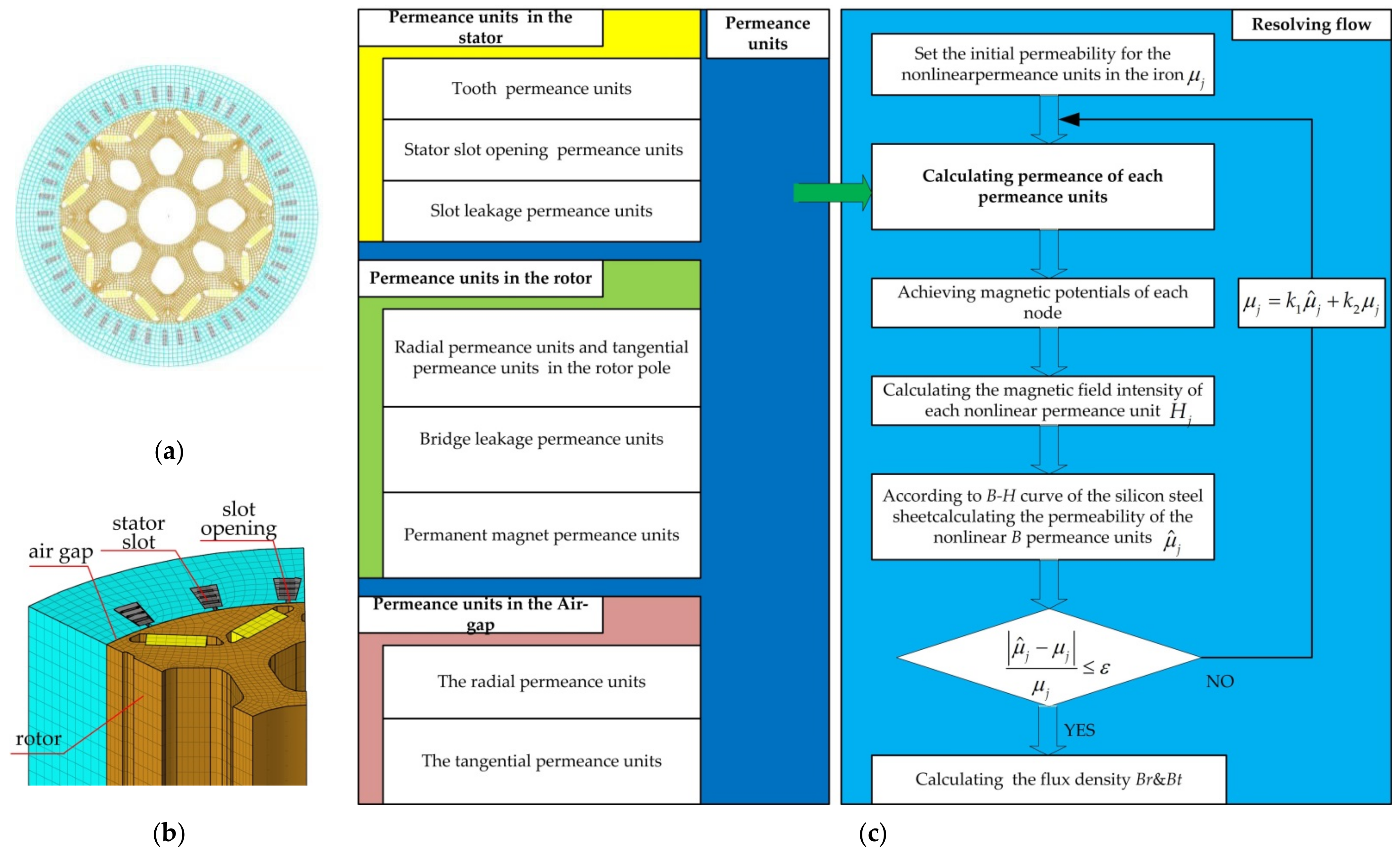
In order to verify the accuracy of the analytical model established in this paper, the finite element model of the IPMSM was established as the benchmark model for comparison, which is shown in Figure 3. In the modeling, the assumptions are as follows: (1) The material is isotropic; (2) the permeability of the material is uniform and does not vary with temperature. According to the actual structure of the IPMSM and the division of permeance units, the flux density distribution of the air-gap is calculated by equivalent magnetic network modeling, and the schematic diagram of the basic modeling process is shown in Figure 3c. Please refer to [31] for more detail on the modeling process.
Several typical geometric structures of the permeance units and the corresponding calculation formula of the permeance are shown in Table 1. In consideration of computational accuracy and speed, two-layer air-gap permeance units are adopted and the mesh thickness of each layer is 0.35 mm.
The main parameters of the IPMSM analyzed in this paper are shown in Table 2. The air-gap magnetic field distributions with and without mixed eccentricity are calculated using established analytical models and are both compared with corresponding results calculated with the finite element models. The radial and tangential components of the air-gap magnetic field are compared separately. The accuracy of the analytical model is characterized by the root mean square percentage error (RMSPE), described as
R M S P E = 1 N d i = 1 N d ( S A i S E i ) 2 S E i 2 × 100 %
where Nd is the number of samples of the radial or tangential component of air-gap magnetic field in one period, SAi is the ith value of the radial or tangential component sequence calculated with the analytical model, and SEi is the ith value of the radial or tangential component sequence calculated with the finite element model.

3. Results and Discussion

3.1. Model Validation

3.1.1. The Normal Case

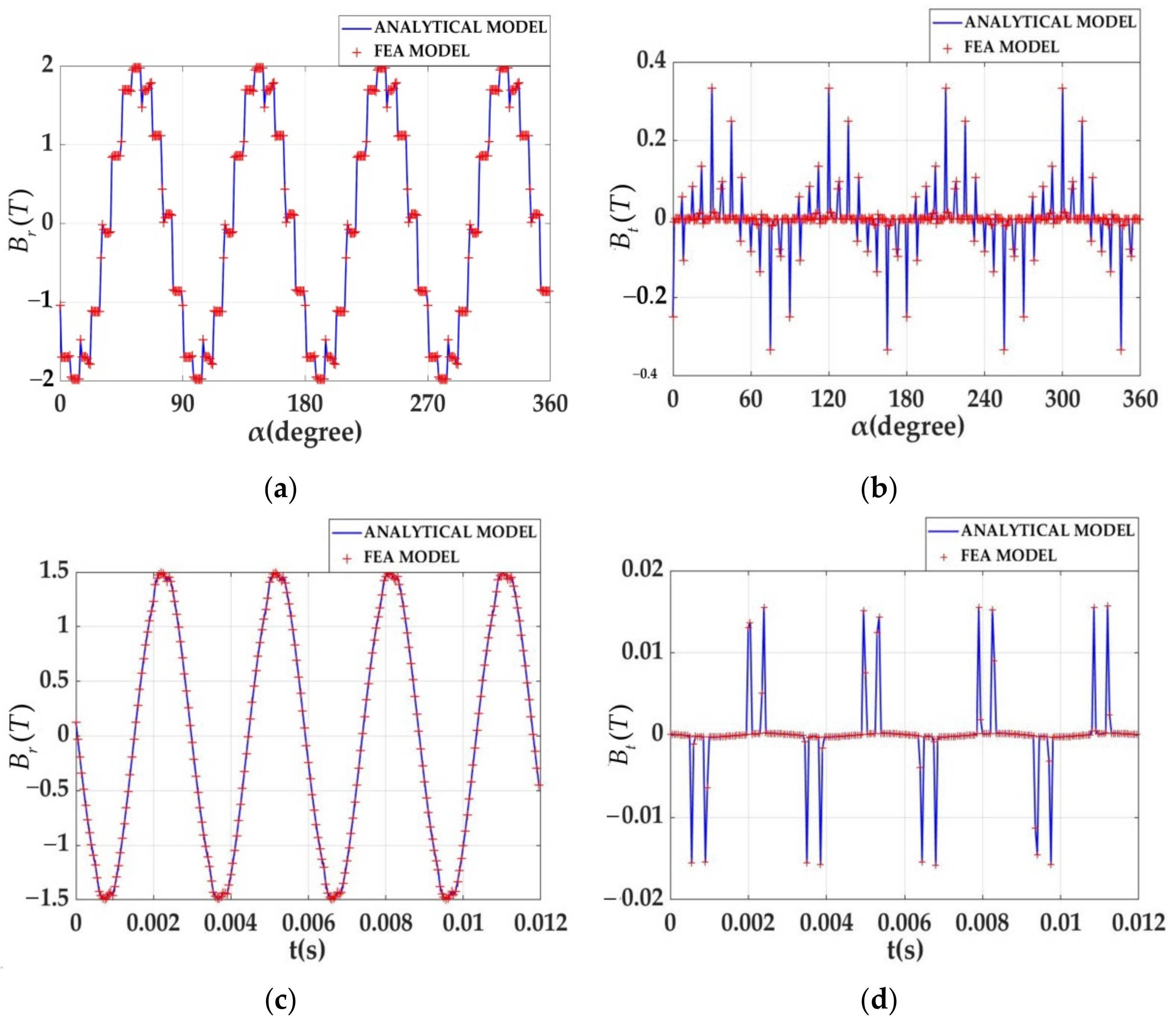
In this section, the accuracy of calculation results of air-gap magnetic field without eccentricity was examined. The spatiotemporal distributions of the radial flux density and tangential flux density of the air-gap magnetic field obtained by analytical method and FEA are shown in Figure 4, where the initial spatial angle of the temporal distribution calculation is 3.7° in this paper.
According to Equation (29), the RMSPEs of the spatial radial component and the spatial tangential component are 0.9% and 0.89%, respectively, while the RMSPEs of the temporal radial component and the temporal tangential component are 1.01% and 1.1%, respectively. This shows that the results calculated by the proposed analytical model are consistent with the results of FEA, which demonstrates the accuracy of the proposed analytical model.

3.1.2. The Eccentric Case

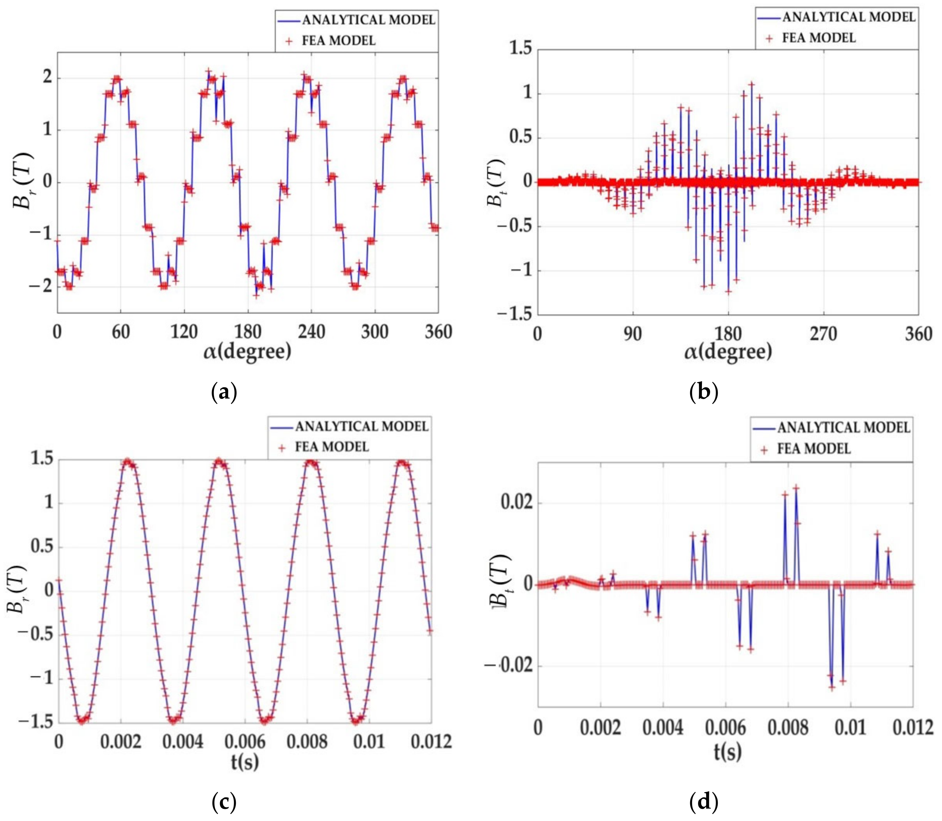
In order to show that the analytical model in this paper can accurately and effectively reflect the phenomenon of eccentricity, the spatiotemporal radial and tangential distributions of the air-gap flux density under the conditions of εS = 50%, and εD = 50% were calculated. Figure 5 shows the spatiotemporal distributions of radial and tangential components of the air-gap flux density. Equation (29) was also used to analyze the model error. The calculation results show that the RMSPEs of the spatial radial and tangential components are 1.02% and 0.97%, respectively. Additionally, RMSPEs of the temporal radial and tangential components are 1.11% and 1.12%, respectively. Therefore, the analytical model of the air-gap magnetic field distribution with mixed eccentricity is consistent with the FEA model, which verifies the accuracy and effectiveness of the proposed modelling method.
In addition, from the spatial diagram of the radial components, the peak values of the magnetic flux density of the air-gap are mainly affected by the magnetic bridge of the rotor and are close to 2T. Especially in the case of mixed eccentricity, the tightest of the air-gap can reach a saturation state. Once saturated, the maximum magnetic density reaches 2.07T, which is consistent with the results of finite element analysis.

3.2. Influence of the Mixed Eccentricity on the Air-Gap Magnetic Field

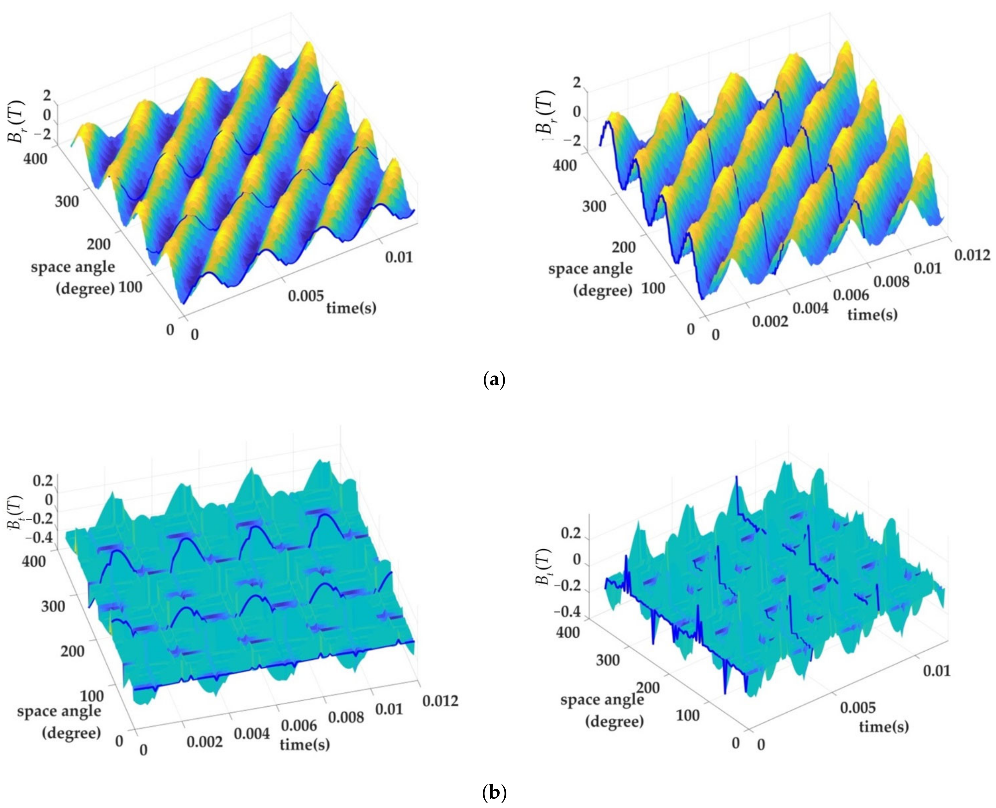
In order to investigate the influence of mixed eccentricity on the spatiotemporal distribution of the air-gap magnetic field, Figure 6 shows the three-dimensional spatiotemporal distribution of air-gap flux density under the conditions of εS = 50% and εD = 50%. Figure 6a shows the three-dimensional spatiotemporal distribution of radial air-gap flux density, and Figure 6b shows the three-dimensional spatiotemporal distribution of tangential air-gap flux density. The blue curves along the x axis (times) are the curves of the variation in radial and tangential flux density with time at a given space angle, while the blue curves along the y axis (space angle) are the curves of the variation of radial and tangential components of air-gap flux density with space angle at a given moment. It can be seen from the figures that, under different space angles, the temporal distributions of the radial and tangential flux density are completely different, while the spatial distributions of the radial and tangential flux density at different times are relatively consistent. Therefore, in the following parts of the paper, only the spatial distribution of the air-gap magnetic field is analyzed.
According to the above calculation, it can be found that mixed eccentricity leads to significant changes in the distribution of the air-gap magnetic field. In order to characterize this change, some features representing the radial and tangential components of the magnetic field were extracted, and their variation between different degrees of mixed eccentricity was analyzed.

3.2.1. Analysis of the Radial Component of the Air-Gap Flux Density

The radial un-symmetry (USYr) and the radial total harmonic distortion rate (THDr) are designed for the radial component of the air-gap flux density, which can be described as
U S Y r = B r m a x B r m i n B r n × 100 %
T H D r = k B r ( k ) B r 1 2 × 100 %
where Br is the spatial distribution of radial component of air-gap flux density, and Brmax and Brmin are the maximum and minimum root mean square values of all periods of Br. Brn is the root mean square value without eccentricity. Br1 is the amplitude of fundamental component of the radial air-gap flux density, and Br(k) is the amplitude of kth harmonic component of radial air-gap flux density.
In order to study the influence of different degrees of static and dynamic eccentricities on radial air-gap flux density, the results of two situations are shown in Table 3; εS = 20% and tεS = 50% for the first situation, while εD = 50% and εD = 20% for the second situation. From the table, we can find that the spatial distribution of the air-gap radial flux density is distorted by mixed eccentricity. Compared with the case without mixed eccentricity, the values of USYr and THDr increase when the mixed eccentricity occurs. In the situation of εS = 50% and εD = 20%, the USYr increases by 0.19%, the amplitude of spatial harmonics increases by 0.09% averagely, and the THDr also increases by 0.02%. It can be seen that the influence of static eccentricity of the rotor on air-gap radial flux density is greater than that of dynamic eccentricity.
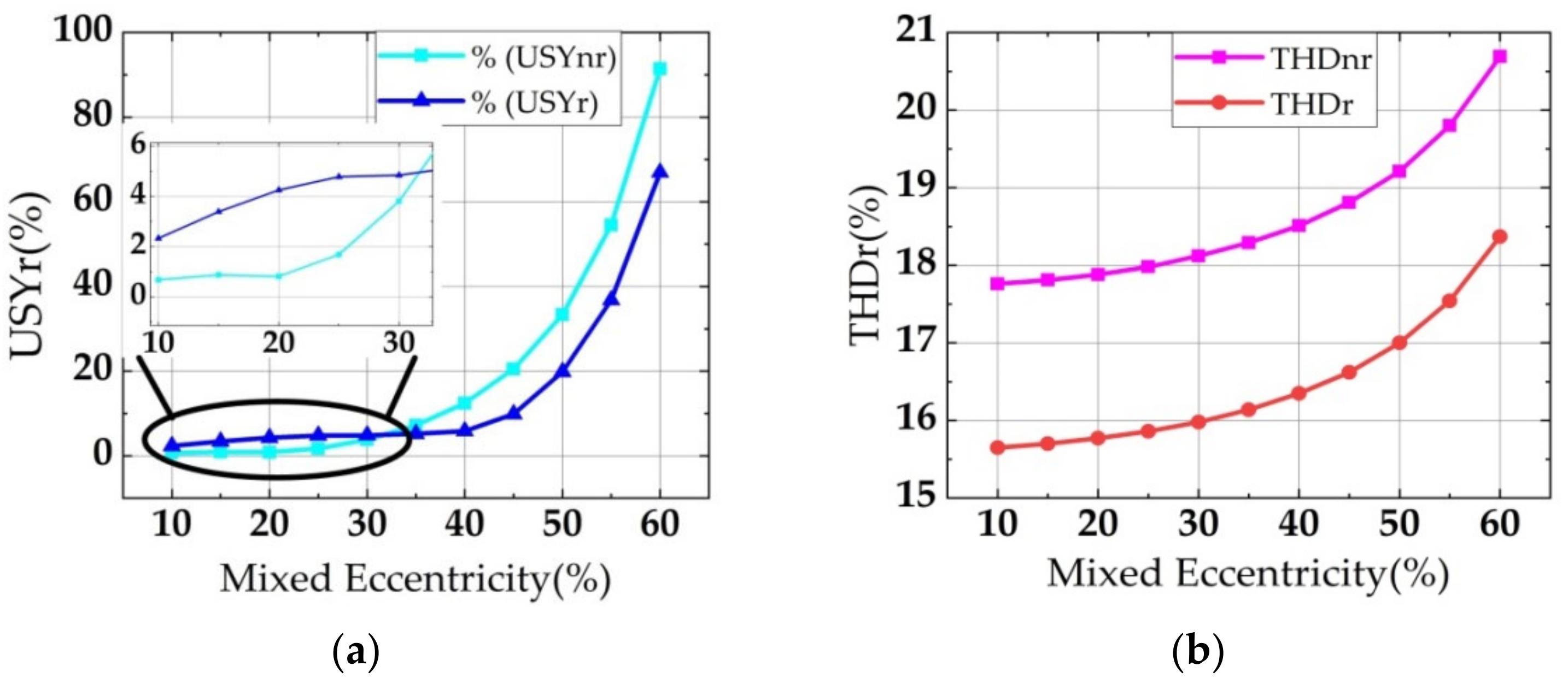
In order to further highlight the influence of mixed eccentricity on the features of radial air-gap flux density, the degrees and steps of static and dynamic eccentricities were set to be the same, so the degree of mixed eccentricity is the same as the degree of static eccentricity or dynamic eccentricity for the analysis of the variation characteristic of Br with a mixed-eccentric fault. The air-gap flux density was calculated when the static eccentricity angle was 2°, and the result is shown in Figure 7. The values of USYr and THDr of the radial air-gap flux density also increase with the increase in the degree of mixed eccentricity. When the degree of the mixed eccentricity is low (εm < 40%), the values of USYr are low and change smoothly, while when the εm > 40%, the values of USYr increase significantly.

3.2.2. Analysis of the Tangential Air-Gap Flux Density Component

We define the tangential un-symmetry (USYt) of the tangential air-gap flux density component as
U S Y t = B t m a x B t m i n B t n × 100 %
where Bt is the spatial distribution of tangential component of air-gap flux density, and Btmax and Btmin are the maximum and minimum root mean square values of all periods of Bt. Btn is the root mean square value without eccentricity.
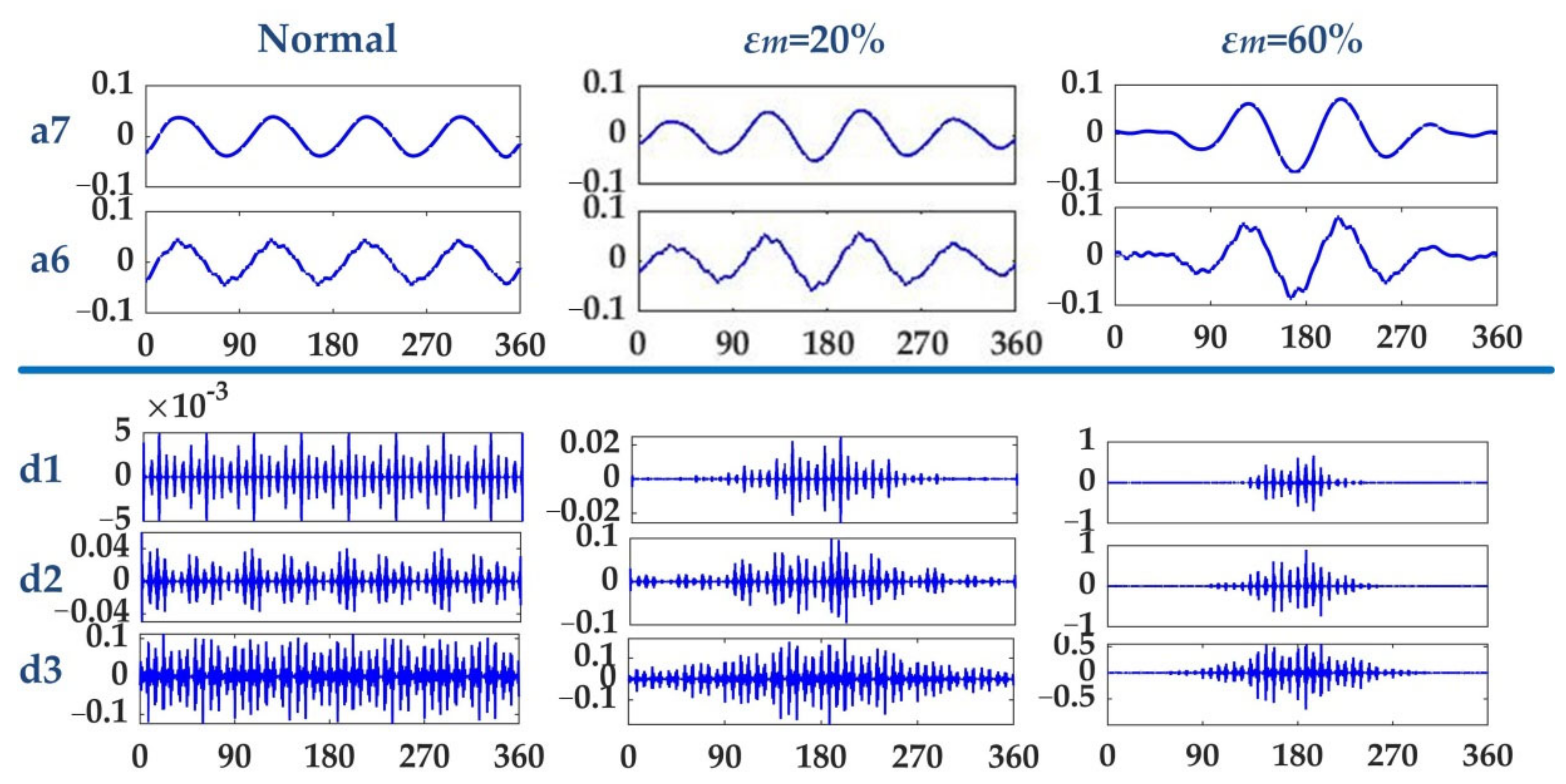
When mixed eccentricity occurs, the tangential air-gap flux density curve will be distorted and become a non-stationary curve. Thus, spectrum analysis based on Fourier transform cannot accurately describe the frequency and amplitude characteristics of tangential air-gap flux density under different spatial angles. In this paper, the wavelet transform method was used to decompose the original tangential air-gap flux density, and the number of decomposition layers was 7. Among them, the low-frequency components a6 and a7 were closer to the envelope of the original signal. As the eccentricity increases, the distortion becomes serious, that is, the asymmetry tends to be serious. The high-frequency components d1, d2, and d3 are obvious periodic signals, and as the degree of eccentricity increases, the signal energy distributions converge toward the center of the samples, as shown in Figure 8.
Therefore, the feature of energy proportion is defined to describe the degree of aggregation of signal energy, which is expressed as
E o i = E M i E T × 100 %
where i = 1,2 are the coefficients of the first layer and the second layer of the high-frequency components of the signal, respectively, signal samples are equally divided into 10 intervals, and EMi is the signal energy of the fifth and sixth intervals in the middle. ET is the total energy of signal samples. The signal energy is calculated by
E = m = 1 N d s ( m ) 2
where Nd is the calculated sample length and s is the calculated sample values.
The samples of low-frequency component a7 were used to calculate the USYt, and the samples of high-frequency components d1, d2, and d3 were used to calculate the Eoi. The results are shown in Figure 9. In Figure 9a, USYt increases significantly with the increase in degree of mixed eccentricity, indicating that mixed eccentricity has a serious impact on the low-frequency component of tangential air-gas flux density. In Figure 9b, Eoi also increases correspondingly. The Eoi of the d1 component is most sensitive to the severity of mixed eccentricity.

3.3. Influence of Bridge Saturation on Air-Gap Magnetic Field with Mixed Eccentricity

In order to analyze the influence of bridge saturation on the air-gap magnetic field distribution with mixed eccentricity, the radial spatial component of air-gap flux density was calculated with the analytical model without considering saturation. Specifically, the calculation was performed by ignoring Equation (16) while solving Equations (17) and (18). Then, the radial un-symmetry USYnr and the radial total harmonic distortion rate THDnr were further calculated for the case without considering bridge saturation and were then compared with the results calculated in Section 3.2.1 in which the bridge saturation was considered, as shown in Figure 10.
It can be seen from Figure 10 that the values of USYnr are lower than those of USYr when the degree of mixed eccentricities are low. In other words, when the analytical model does not consider the bridge saturation, the calculation results show that the eccentricity has little effect on the magnetic field. So, it is difficult to identify the characteristics of the early stage of eccentricity fault. When the degree of mixed eccentricity is high, the increase in USYnr is greater than that of USYr. That is, it seems that the impact on the magnetic field is greater than in reality when the model without considering the bridge saturation, which will cause misjudgment of the degree of eccentricity. In addition, we found that the bridge saturation has little effect on THDnr.

4. Conclusions

Mixed eccentricity is a common fault of IPMSMs, which will distort the air-gap magnetic field and affect the motor performance. In this paper, an analytical model of the air-gap magnetic field distribution in IPMSMs with mixed eccentricity considering the effect of bridge saturation is established, and the accuracy is verified by comparison with finite element analysis. On this basis, features of the air-gap magnetic field distribution that can effectively reflect the mixed eccentricity fault are extracted. The calculation results show that features change significantly with the variation in the degree of mixed eccentricity, which can accurately reflect the evolution process and characteristics of the mixed eccentricity. In the future, we will further study the relationship between the features extracted in this paper and the monitored quantities such as electrical parameters and mechanical parameters and achieve early detection and diagnosis of mixed eccentricity.

Author Contributions

Conceptualization, Y.S. and P.L.; methodology, Y.S.; software, Y.S. and P.L.; validation, Y.S. and J.C.; formal analysis, P.L.; investigation, Y.S. and J.C.; resources, L.G.; data curation, Y.S. and J.C.; writing—original draft preparation, Y.S.; writing—review and editing, P.L.; supervision, L.G.; project administration, L.G. and D.C. All authors have read and agreed to the published version of the manuscript.

Funding

This research was funded by the key research and development program of Shaanxi Province, China (Grant no. 2022GY-134), Science and Technology Foundation of Xi’an University of Architecture and Technology, China (Grant no. ZR19059), Natural Science Foundation of Guangdong Province, China (Grant no. 2021A1515011423), and Shenzhen basic research project (Grant no. JCYJ20190806172007629).

Institutional Review Board Statement

Not applicable.

Informed Consent Statement

Not applicable.

Data Availability Statement

Not applicable.

Conflicts of Interest

The authors declare no conflict of interest.

References

  1. Čorović, S.; Miljavec, D. Modal analysis and rotor-dynamics of an interior permanent magnet synchronous motor: An experimental and theoretical study. Appl. Sci. 2020, 10, 5881. [Google Scholar] [CrossRef]
  2. Zhang, G.; Yu, W.; Hua, W.; Cao, R.; Qiu, H.; Guo, A. The Design and Optimization of an Interior, Permanent Magnet Synchronous Machine Applied in an Electric Traction Vehicle Requiring a Low Torque Ripple. Appl. Sci. 2019, 9, 3634. [Google Scholar] [CrossRef] [Green Version]
  3. Zhu, L.; Jiang, S.; Zhu, Z.; Chan, C. Analytical modeling of open-circuit air-gap field distributions in multisegment and multilayer interior permanent-magnet machines. IEEE Trans. Magn. 2009, 45, 3121–3130. [Google Scholar] [CrossRef] [Green Version]
  4. Zhang, Z.; Xia, C.; Yan, Y.; Geng, Q.; Shi, T. A hybrid analytical model for open-circuit field calculation of multilayer interior permanent magnet machines. J. Magn. Magn. Mater. 2017, 435, 136–145. [Google Scholar] [CrossRef]
  5. Tian, K.; Zhang, T.; Ai, Y.; Zhang, W. Induction motors dynamic eccentricity fault diagnosis based on the combined use of WPD and EMD-simulation study. Appl. Sci. 2018, 8, 1709. [Google Scholar] [CrossRef] [Green Version]
  6. Liu, Z.; Huang, J.; He, S. Diagnosis of air-gap eccentricity and partial demagnetisation of an interior permanent magnet synchronous motor based on inverse transient complex inductance vector theory. IET Electr. Power Appl. 2018, 12, 1166–1175. [Google Scholar] [CrossRef]
  7. Liu, Z.; Huang, J.; Li, B. Diagnosing and distinguishing rotor eccentricity from partial demagnetisation of interior PMSM based on fluctuation of high-frequency d-axis inductance and rotor flux. IET Electr. Power Appl. 2017, 11, 1265–1275. [Google Scholar] [CrossRef]
  8. Masmoudi, A. Fractional-Slot Concentrated Windings: Design and Analysis. In Design and Electromagnetic Feature Analysis of AC Rotating Machines; Springer: Berlin/Heidelberg, Germany, 2019; pp. 55–85. [Google Scholar]
  9. Li, L.; Li, W.; Li, D.; Zhang, X.; Fan, Y. Influence of sleeve thickness and various structures on eddy current losses of rotor parts and temperature field in surface mounted permanent-magnet synchronous motor. IET Electr. Power Appl. 2018, 12, 1183–1191. [Google Scholar] [CrossRef]
  10. An, Y.; Ma, C.; Zhang, N.; Guo, Y.; Degano, M.; Gerada, C.; Bu, F.; Yin, X.; Li, Q.; Zhou, S. Calculation model of armature reaction magnetic field of interior permanent magnet synchronous motor with segmented skewed poles. IEEE Trans. Energy Convers. 2021, 37, 1115–1123. [Google Scholar] [CrossRef]
  11. Caruso, M.; Di Tommaso, A.O.; Miceli, R.; Viola, F. A Cogging Torque Minimization Procedure for Interior Permanent Magnet Synchronous Motors Based on a Progressive Modification of the Rotor Lamination Geometry. Energies 2022, 15, 4956. [Google Scholar] [CrossRef]
  12. Park, Y.; Fernandez, D.; Lee, S.B.; Hyun, D.; Jeong, M.; Kommuri, S.K.; Cho, C.; Reigosa, D.D.; Briz, F. Online detection of rotor eccentricity and demagnetization faults in PMSMs based on hall-effect field sensor measurements. IEEE Trans. Ind. Appl. 2018, 55, 2499–2509. [Google Scholar] [CrossRef]
  13. Li, Y.; Lu, Q.; Zhu, Z.Q. Unbalanced magnetic force prediction in permanent magnet machines with rotor eccentricity by improved superposition method. IET Electr. Power Appl. 2017, 11, 1095–1104. [Google Scholar] [CrossRef]
  14. Kim, H.J.; Moon, J.W. Improved rotor structures for increasing flux per pole of permanent magnet synchronous motor. IET Electr. Power Appl. 2018, 12, 415–422. [Google Scholar] [CrossRef]
  15. Azarinfar, H.; Aghaebrahimi, M.R. Design, analysis and fabrication of a novel transverse flux permanent magnet machine with disk rotor. Appl. Sci. 2017, 7, 860. [Google Scholar] [CrossRef] [Green Version]
  16. Krämer, C.; Kugi, A.; Kemmetmüller, W. Modeling of a permanent magnet linear synchronous motor using magnetic equivalent circuits. Mechatronics 2021, 76, 102558. [Google Scholar] [CrossRef]
  17. Song, I.-S.; Jo, B.-W.; Kim, K.-C. Analysis of an IPMSM Hybrid Magnetic Equivalent Circuit. Energies 2021, 14, 5011. [Google Scholar] [CrossRef]
  18. Yu, Z.; Li, Y.; Jing, Y.; Du, J.; Wang, Z. Analytical model for magnetic field calculation of SPMSM with chamfered pole considering iron core saturation. IET Electr. Power Appl. 2020, 14, 1856–1864. [Google Scholar] [CrossRef]
  19. Liang, P.; Chai, F.; Li, Y.; Pei, Y. Analytical prediction of magnetic field distribution in spoke-type permanent-magnet synchronous machines accounting for bridge saturation and magnet shape. IEEE Trans. Ind. Electron. 2016, 64, 3479–3488. [Google Scholar] [CrossRef]
  20. Yang, J.; Chen, J.; Yang, G.; Zhao, S.; Zhang, C. Accurate Calculation of Magnetic Field of Same-Pole and Same-Slot Surface-Mounted Three-Phase Permanent Magnet Synchronous Motor. IEEE Trans. Magn. 2022, 58, 8204910. [Google Scholar] [CrossRef]
  21. Shin, K.-H.; Cho, H.-W.; Lee, S.-H.; Choi, J.-Y. Armature reaction field and inductance calculations for a permanent magnet linear synchronous machine based on subdomain model. IEEE Trans. Magn. 2017, 53, 8105804. [Google Scholar] [CrossRef]
  22. Ma, F.; Yin, H.; Wei, L.; Wu, L.; Gu, C. Analytical calculation of armature reaction field of the interior permanent magnet motor. Energies 2018, 11, 2375. [Google Scholar] [CrossRef] [Green Version]
  23. Su, P.; Hua, W.; Wu, Z.; Han, P.; Cheng, M. Analysis of the operation principle for rotor-permanent-magnet flux-switching machines. IEEE Trans. Ind. Electron. 2017, 65, 1062–1073. [Google Scholar] [CrossRef]
  24. Zheng, J.; Zhao, W.; Ji, J.; Zhu, J.; Gu, C.; Zhu, S. Design to Reduce Rotor Losses in Fault-Tolerant Permanent-Magnet Machines. IEEE Trans. Ind. Electron. 2018, 65, 8476–8487. [Google Scholar] [CrossRef]
  25. Zhu, X.; Hua, W.; Wang, B.; Dai, N. Comparison of stator-and rotor-surface-mounted PM brushless machines. IET Electr. Power Appl. 2020, 14, 62–70. [Google Scholar] [CrossRef]
  26. Cheng, M.; Zhu, X.; Wang, Y.; Wang, R.; Wang, W. Effect and inhibition method of armature-reaction field on superconducting coil in field-modulation superconducting electrical machine. IEEE Trans. Energy Convers. 2019, 35, 279–291. [Google Scholar] [CrossRef]
  27. Ma, C.; Li, Q.; Lu, H.; Liu, Y.; Gao, H. Analytical model for armature reaction of outer rotor brushless permanent magnet DC motor. IET Electr. Power Appl. 2018, 12, 651–657. [Google Scholar] [CrossRef]
  28. Deng, W.; Zuo, S. Comparative study of sideband electromagnetic force in internal and external rotor PMSMs with SVPWM technique. IEEE Trans. Ind. Electron. 2018, 66, 956–966. [Google Scholar] [CrossRef]
  29. Ebrahimi, B.M.; Faiz, J. Configuration impacts on eccentricity fault detection in permanent magnet synchronous motors. IEEE Trans. Magn. 2012, 48, 903–906. [Google Scholar] [CrossRef]
  30. Rezaee-Alam, F.; Rezaeealam, B.; Faiz, J. Unbalanced magnetic force analysis in eccentric surface permanent-magnet motors using an improved conformal mapping method. IEEE Trans. Energy Convers. 2016, 32, 146–154. [Google Scholar] [CrossRef]
  31. Guo, L.; Xia, C.; Wang, H.; Wang, Z.; Shi, T. Improved equivalent magnetic network modeling for analyzing working points of PMs in interior permanent magnet machine. J. Magn. Magn. Mater. 2018, 454, 39–50. [Google Scholar] [CrossRef]
Figure 1. The equivalent magnetic circuit.
Applsci 12 11956 g001
Figure 2. The geometric model of the air-gap with mixed eccentricity. (a) ω t δ < 2 k π ; (b) 2 k π ω t δ < ( 2 k + 1 ) π ; (c) ( 2 k + 1 ) π ω t δ < 2 ( k + 1 ) π .
Applsci 12 11956 g002
Figure 3. The finite element model of the IPMSM. (a) End view drawing; (b) grid diagram; (c) the basic modeling process.
Applsci 12 11956 g003
Figure 4. The spatial and temporal distributions of the normal air-gap flux density. (a) The spatial distribution of radial flux density; (b) The spatial distribution of tangential flux density; (c) The temporal distribution of radial flux density; (d) The temporal distribution of tangential flux density.
Applsci 12 11956 g004
Figure 5. The spatial and temporal distributions of air-gap flux density with mixed eccentricity. (a) The spatial distribution of radial flux density; (b) The spatial distribution of tangential flux density; (c) The temporal distribution of radial flux density; (d) The temporal distribution of tangential flux density.
Applsci 12 11956 g005
Figure 6. The three-dimensional spatiotemporal characteristics of air-gap magnetic field with mixed eccentricity. (a) The spatiotemporal distribution of radial component; (b) the spatiotemporal distribution of tangential component.
Applsci 12 11956 g006
Figure 7. The values of USYr and THDr. (a) USYr; (b) THDr.
Applsci 12 11956 g007
Figure 8. The results of wavelet decomposition of tangential air-gap flux density.
Applsci 12 11956 g008
Figure 9. The influence of mixed eccentricity on the values of USYt and EOi: (a) USYt; (b) EOi.
Applsci 12 11956 g009
Figure 10. The influence of the bridge saturation on USYnr and THDnr: (a) USYn; (b) THDnr.
Applsci 12 11956 g010
Table 1. The types of finite elements.
Permeance UnitsPermeance FormulasGeometric Structure
Applsci 12 11956 i001
Rectangular
G = μ l 1 l 2 / h stator slot
rotor pole
air-gap
magnetic bridge
Applsci 12 11956 i002
Trapezoidal
G = μ a 1 + a 2 b / 2 h stator tooth
Applsci 12 11956 i003
Fan-shaped
G = 4 μ l 3 / π stator slot opening
Table 2. The main parameters of IPMSM.
Parameters Numerical ValuesParametersNumerical Values
Rated power Pn160 kWAxial length of the iron core Lr130 mm
Rated speed n05100 rpmNumber of wire layers per groove Nt4
Number of pole-pairs p4Number of parallel branches Np2
Number of slots Ns48Magnet thickness hM6 mm
Radius of the slot bottom Rsb93.6 mmWidth of the ermanent magnet LM17 mm
Radius of the slot top Rst80.6 mmPermeability of the vacuum μ04π × 10−7 H/m
Groove width bsa0.05 radRelative permeability of the permanent magnet μr1.059
Rabbet width boa0.011 radWidth of the bridge αb0.035 rad
Inner radius of the stator RS79.8 mmEnd thickness of the bridge hb2.1 mm
External radius of the rotor Rr79.1 mmInterpolar thickness of the bridge hi2.8 mm
Basic frequency f0340 Hz
Table 3. The spatial harmonic amplitudes, USYr and THDr with different mixed eccentricities.
Mixed Eccentric ConditionsSpatial Harmonic AmplitudesUSYrTHDr
(%)
11132325354759718385(%)
Normal0.20840.13090.1140.05190.076350.056580.043920.033790.026240.01964015.52
εS = 20% & εD = 50%0.21280.13550.12460.058020.092880.077380.066740.054480.044710.043445.2117.12
εS = 50% & εD = 20%0.21280.13560.12480.058090.093150.077740.067170.054880.045080.043475.4017.14
Publisher’s Note: MDPI stays neutral with regard to jurisdictional claims in published maps and institutional affiliations.