Review

Research Developments of Aerostatic Thrust Bearings: A Review

School of Energy and Power Engineering, Xi’an Jiaotong University, Xi’an 710049, China
*
Author to whom correspondence should be addressed.
Appl. Sci. 2022, 12(23), 11887; https://doi.org/10.3390/app122311887
Submission received: 31 October 2022 / Revised: 17 November 2022 / Accepted: 20 November 2022 / Published: 22 November 2022
(This article belongs to the Special Issue New Achievements in Structural Dynamics Analysis)

Abstract

:
In aerostatic thrust bearings (ATBs), a high-pressure gas film with a certain bearing capacity and stiffness is formed by passing high-pressure gas between the moving surface and the static surface. Aerostatic bearings have outstanding advantages in the following aspects: high precision, high speed, and long service life, etc. They are widely used in many fields, such as high-speed air spindles, precision machine tools, air-bearing guideways, turbine machinery, and high-speed drills. With the pursuit of higher efficiency and high-precision machining machinery, there is an increasing demand for high-performance ATBs. Much effort has been spent on the study of ATBs, such as improvements in load capacity and stiffness, and the enhancement of stability. Some significant progress has been achieved. In this paper, the research developments of ATBs are summarized from several aspects, such as theoretical models and experimental methods, static performance, dynamic performance, and applications. In addition, insights on the breakthrough and development trends of ATBs are put forward. It is hoped that this paper can provide some guidance for the design and application of ATBs.

1. Introduction

In aerostatic thrust bearings (ATBs), high-pressure gas is introduced between the moving surface and the static surface. A high-pressure gas film with a certain bearing capacity and stiffness is formed between the friction pairs. Thus, aerostatic bearings have the following advantages, such as low friction, high speed, high precision, and long service life [1]. A schematic photograph of aerostatic thrust bearings (ATBs) is depicted in Figure 1a. The pressurized gas is fed from an external source. It enters the bearing gap through the restrictor and finally flows to the atmosphere at the outer boundary of the bearing, as shown in Figure 1b. The pressure redistribution and throttling effect of gas are achieved in this process. The pressure distribution in the gas film of the ATB is shown in Figure 1c. The pressure near the orifice is higher, and the gas pressure gradually decreases when it is far away from the orifice. The velocity contour near the orifice is shown in Figure 1d [1]. Along the radial direction, the velocity decreases gradually.
Aerostat thrust bearings are widely used in many fields. The typical applications are high-speed machinery, and high-precision applications, as shown in Figure 2. In high-speed applications, common applications are aerostatic spindles and turbo machines. For aerostatic spindles, a high rotational speed is required to maintain machine spindle speed [2,3]. Large load capacity is expected during the fly-cutter milling process. For turbomachines [4], more gas can be processed while running at high speed. In high-precision applications, common applications are precision machine tools, precision measuring equipment and lithography-associated production equipment [5,6]. Aerostatic guideways are applied to ensure precision linear motion with high repeatability and high resolution [7]. With the development of precision machining, the accuracy of motion is required to be higher, even at the sub-nanometer level [8]. Therefore, higher requirements are placed on the performance of ATBs, such as load-carrying capacity, stiffness, and stability. It is hoped to improve the stability of ATBs while still ensuring high static performance.
The performance analysis of ATBs is mainly categorized into two types, static and dynamic characterization. In the static performance of ATBs, the main physical parameters are load capacity, static stiffness, and the mass consumption of pressurized gas. They are usually evaluated as a function of gas film clearance. The dynamic performance of ATBs mainly focuses on stability study. In stability evaluation, the main physical parameters are dynamic stiffness and damping coefficients. It is necessary to evaluate the margins of stability of ATBs [9].
In the static and dynamic performance of ATBs, much progress has been achieved. At present, there are still some challenges in the application process. The first limitation is the low stiffness and load capacity of ATBs, which are only about 1/1000 of oil bearings. The second limitation is the dynamic performance of aerostatic bearings, which determines the dynamic response of equipment, to a large extent. The difficulties lie in how to obtain stable dynamic performance by designing bearings with appropriate parameters and operating conditions. In addition, the “pneumatic hammer” is a key problem in the application of ATBs, which has a great influence on the stability of aerostatic thrust bearings.
At present, a significant improvement in the performance of ATBs has been achieved, but the limitations of ATBs have not been completely overcome. In order to promote the development of high-performance ATBs, it is necessary to make a comprehensive summary of ATBs. In this paper, the research developments of ATBs are summarized from several aspects, theoretical model and experimental study, static performance and dynamic performance, and applications of ATBs. In addition, the development trends of ATBs are discussed. It is hoped that this paper can provide guidance for the further application of ATBs.

2. Theoretical Models and Experiment Methods

2.1. Theoretical Model

With the developments of ATBs, the theoretical model is continuously improved. In the early stages, the simplified Reynolds equation was solved to predict the performance of the aerostatic bearing. The steady-state pressure governing the Equation of aerostatic bearing in dimensionless form is shown in Equation (1) [10].
x ¯ h ¯ 3 p ¯ 2 x ¯ + z ¯ h ¯ 3 p ¯ 2 z ¯ + Q ¯ δ i = Λ x p ¯ h ¯ x ¯ + Λ z p ¯ h ¯ z ¯
where x ¯ and z ¯ are dimensionless coordinates, h ¯ is the dimensionless thickness of the gas film, p ¯ is the dimensionless pressure, Q ¯ is the dimensionless mass flow factor, δi is a constant coefficient. Λ x and Λ z are dimensionless bearing numbers in the x and z directions. The definitions of the above parameters are shown in Equation (2) [10].
h ¯ = h h m , x ¯ = x l , z ¯ = z l , p ¯ = p p s , Q ¯ = 24 η l 2 p a h m 3 p s 2 ρ a ρ v ˜ , Λ x = 12 η u l h m 2 p s , Λ z = 12 η w l h m 2 p s
where h is the thickness of the gas film, hm is the reference gas film thickness, x and z are coordinates, l is the characteristic length, p is the gas pressure, ρ is the gas density, η is the gas dynamic viscosity, v ˜ is the velocity of orifice gas flow, u and ω are the velocities.
In the solution of the Reynolds equation, how to accurately calculate the pressure and the flow rate through the feed hole was the focus of the research. Later, it was found that the pressure from feed holes to the outlet of the aerostatic bearings does not monotonically decrease. The pressure increases slightly after a sudden drop around the feed hole. Due to the complexity of three-dimensional gas flow and some assumptions in solving the Reynolds equation, the traditional Reynolds equation was insufficient to capture these phenomena accurately. Gradually, more flow characteristics such as supersonic flow, turbulence, gas vortex, and shock wave were discussed [11,12,13,14]. The flow characteristics and fluctuating pressure of ATB are shown in Figure 3 [15]. In recent decades, the demands for the high performance of ATBs are increasing, so it is necessary to study the flow characteristics from a microscopic perspective. To obtain more accurate pressure distribution and its time-dependent characteristics, solving the complete three-dimensional N-S equation has become the most common and acceptable method. The theoretical model is introduced from the following three aspects, gas flow in ATBs, velocity slip effect, and multi-physics coupling.

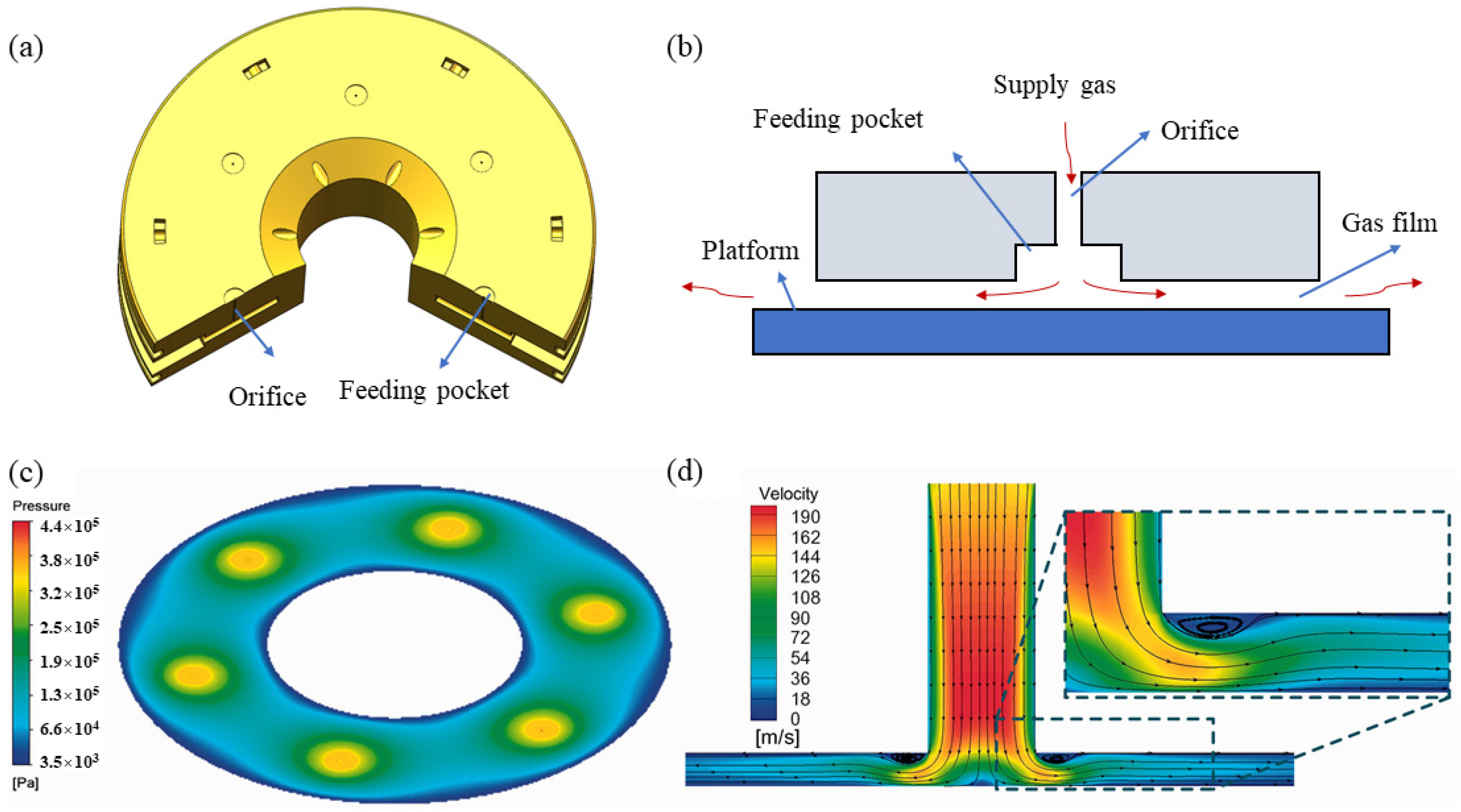
2.1.1. Gas Flow in ATBs

In the initial study, many scholars assumed the gas flow in the bearing was laminar. It was gradually found that the actual gas flow was much more complex. The gas film gap is extremely tiny compared with the bearing size, in the order of 1/1000, which leads to complex flow in the bearing. The gas flow in ATBs has been investigated by many scholars. Mori, H. studied the pressure distribution in the gas clearance of the parallel disk ATBs [11]. There was a sharp pressure drop at the outlet of the orifice of the aerostatic bearing. The pressure distribution in the gas film did not drop steadily from the outlet of the orifice to the outlet of the bearings. It no longer followed the Reynolds lubrication equation. An empirical model was introduced to predict this phenomenon and showed a good agreement with experimental data [16]. The pressure variations in the region around the inlet were accurately predicted using this model. In addition, the feeding system is closely related to the type of restrictor. The flow characteristics through feeding systems become more complicated considering the orifice shape. In order to predict the bearing performance more accurately by solving the Reynolds equation, it is necessary to know the flow characteristics and downstream pressures of the feeding system [17].

2.1.2. Velocity Slip Effect

For gas in the micro clearance of bearings, the molecular mean free path of the gas cannot be neglected compared with the bearing clearance. Velocity slip is more prone to occur at the solid–gas interface. This phenomenon was verified experimentally by Yang [18]. In addition, Hsia, Y. T. carried out an experimental study on gas bearings with clearances below 0.25 microns and validated the slop-flow theory [19]. Moreover, the velocity slip influence on bearing performance was studied in theoretical calculation. Mitsuya, Y. T. applied the surface adjustment coefficient to the traditional gas Reynolds Equation [20]. Chen, D. J. introduced the Navier velocity slip model to improve the theoretical model of the aerostatic guideways. It was found that the first-order velocity slip model was more suitable to predict the performance of aerostatic guideways [21,22]. All the above results show that it is necessary to consider the velocity slip effect in the design of ATBs.

2.1.3. Multiphysics Coupling

In ATBs, the physical parameters of the gas film are closely related to the lubricated surface, boundary velocity slip, bearing structure thermal deformation, and other factors. With the increasing complexity of the system including aerostatic bearings and supported components, it is necessary to establish a more accurate numerical model considering the coupling of multiple physics [10]. Aguirre, G. [23] established a simulation model considering the coupling of structure flexibility, fluid dynamics, piezoelectricity, and control. This model was in good agreement with the experimental results. Lu, L. H. proposed a fluid–structure interaction model to predict the stiffness of an aerostatic spindle. The prediction error is only 2.04% [24]. Other studies on parametric optimization were also carried out based on this model [25,26]. In addition, Gao, S. Y. [2] investigated the performance of aerostatic spindles considering the model of the structure, fluid dynamics, thermal transfer, and electromagnetics. Maamari, N. presented a dynamic model to investigate the damping characteristics of aerostatic bearings considering fluid–structure coupling [27]. Yan, R. Z. revealed the deformation law of the guideway with different materials and found the appropriate material for guideways [28].

2.2. Experimental Methods

Experimental methods are vital approaches to studying the performance of ATBs. In the early period, the experimental method was the principal method due to some limitations of theoretical modeling methods. Many phenomena are found in the experimental process, which also inspired scholars to explore the mechanism of ATBs in depth theoretically. With the development of experimental technology, experimental methods are continuously improving [29]. Experimental methods are introduced from the following aspects: measurement of pressure distribution, measurement of load capacity and gas film, measurement of dynamic characteristics, and the experimental facilities of ATBs.

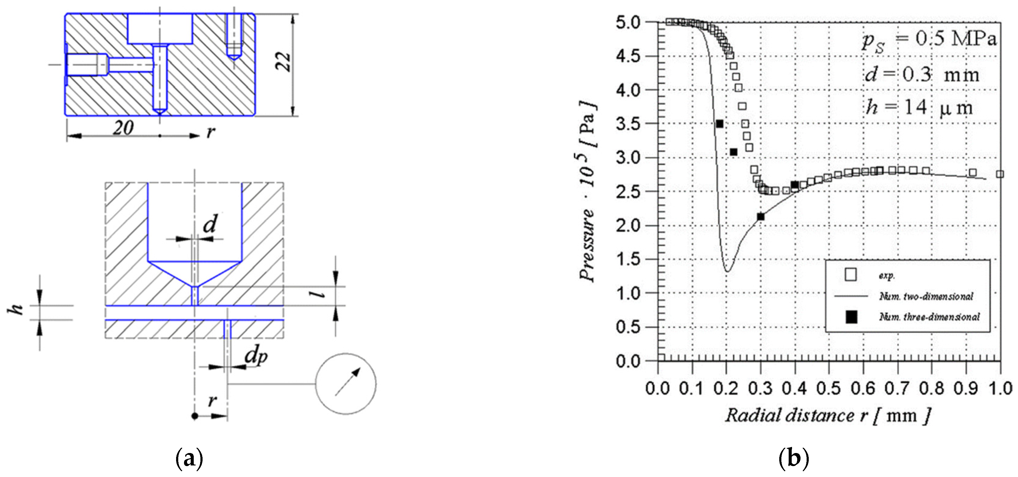
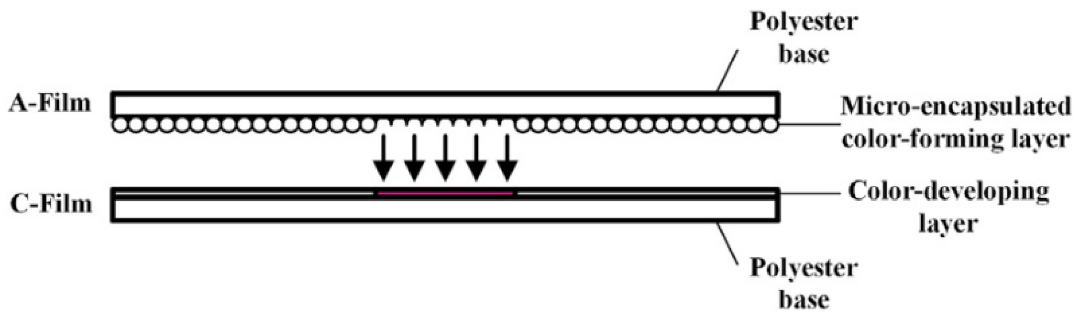
2.2.1. Measurement of Pressure Distribution

The gas film clearance is extremely tiny, usually at the level of 10 μm. It is relatively difficult to obtain accurate measurements of pressure distribution in the bearing clearance. There are two main methods of pressure distribution measurement.
The first method is to connect the pressure sensor to the orifice to measure the pressure distribution in the gas film. The orifice is drilled on one of the pad’s surfaces [30,31]. This small hole is called the flow intake (dp = 0.2 mm) in the literature [32]. The detail of flow intake is shown in Figure 4a. The pressure distribution using this method shows a good agreement with the numerical simulation result, as shown in Figure 4b. However, the method of connecting the pressure sensor to the orifice plate still has some disadvantages. Firstly, non-negligible disturbances to the airflow in the thin gap appear and considerable measurement errors occur. In addition, the amount of experimental data obtained by this method is limited, both in terms of location and quantity. This method has been improved in the literature [33,34,35,36]. The supporting element has been replaced by a linear guideway with position control capability. More pressure data of bearing clearance can be obtained in one single experiment.
Another measurement method of pressure distribution was proposed by Zhou, Y.J. [37], named the pressure-sensitive film measurement method. With the application of pressure, the pressure-sensitive films produce a visible response on the surface in the form of a stain or imprint, as shown in Figure 5. It consists of the A-film and the C-film. The A-film is attached with a micro-encapsulated color-forming layer, and the C-film is made of a color-developing layer. There are numerous microscopic bubbles (2~26 μm diameter) in the color-forming layer, which enclose the colorless liquid. A number of these bubbles burst depending on the magnitude of the applied pressure. Then, these bubbles react with the color-developing layer, producing a pink stain. With increasing pressure, more bubbles burst and a deeper stain occurs. This property is very conducive to the measurement of stain intensity and 2D pressure distribution. In addition, this experimental measurement method has the merits of easy operation, high spatial resolution, and high accuracy. This method demonstrates effectiveness when applied to different forms of bearings. However, this method has strict requirements for calibration, process, and recognition of the image. The roughness of the film surface is strictly required to avoid additional errors.

2.2.2. Measurement of Load Capacity and Gas Film

It is relatively difficult to test the load capacity of the bearing under moving conditions, especially at ultra-high speed. Therefore, most tests are currently carried out under static conditions. Vahdati, M. [38] applied different loads to the guideway. The film gaps in the X and Y directions were measured using an indicator clock, as shown in Figure 6a. Bhat, N. [39] adopted two pressure transducers to measure the load capacity, as shown in Figure 6b. Four displacement sensors were used to measure the gas film thickness between the bearing and the reaction plate. Similar to the method in the literature [39], Cui, H. L. measured the load capacity of the aerostatic thrust pad bearing using the load transducer, as shown in Figure 6c. The gas film thickness was measured by a displacement sensor (TESATRONONIC-TT80) [40].

2.2.3. Measurement of Dynamic Characteristics

The measurement of dynamic characteristics is achieved by measuring the dynamic force generated in the bearing film. The dynamic forces are the results of harmonic variation, either (i) in the film thickness, at constant supply pressure, or (ii) in the supply pressure, at a constant film thickness. The measurement of the dynamic characteristics is also a challenge, owing to the small gap sizes involved. In general, the first type of measurement is more convenient and suitable considering the measurement procedure and error estimation [41].

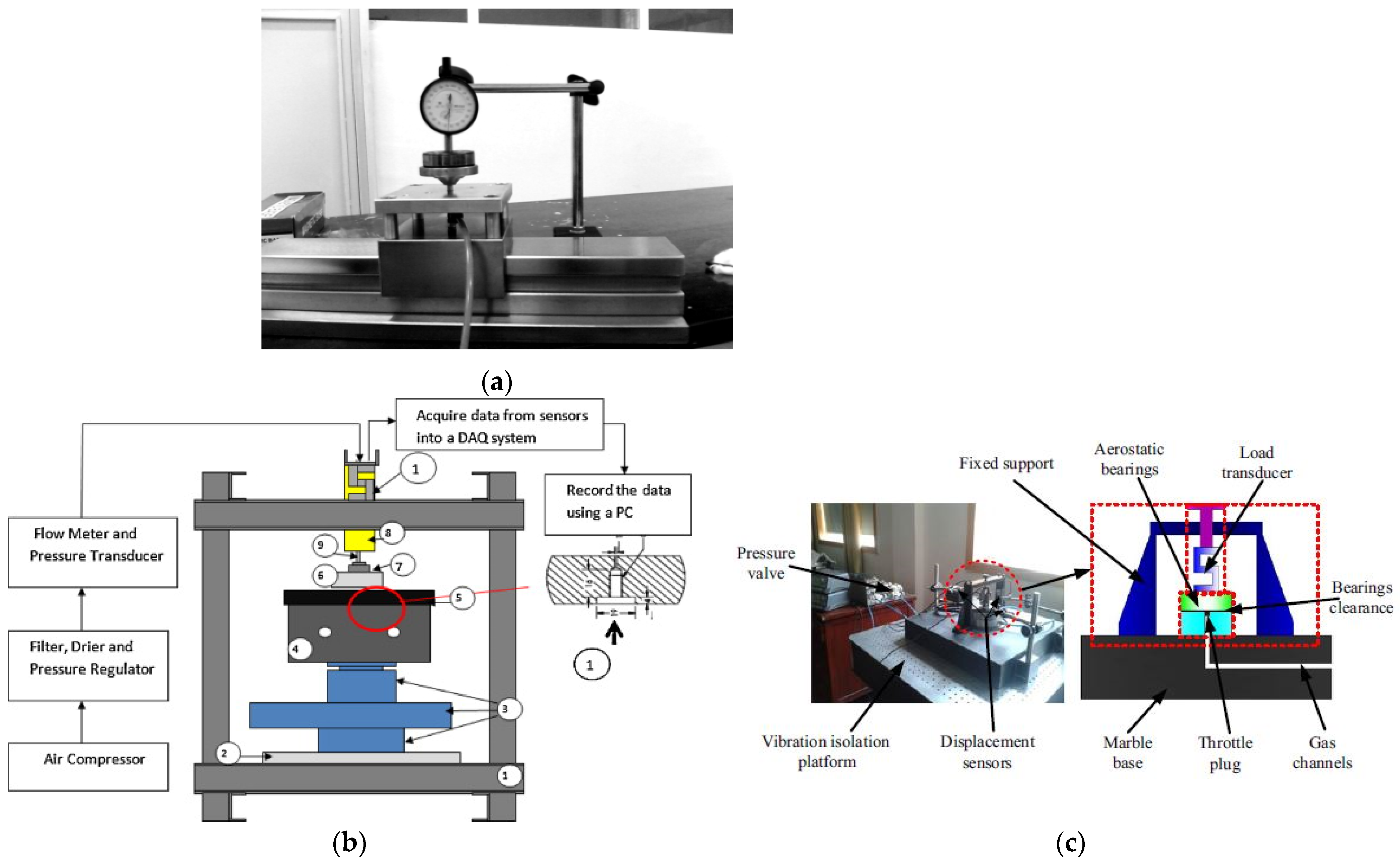
2.2.4. Experimental Facilities of ATBs

At present, many novel experimental techniques have been applied in the research of aerostatic bearings, especially visualization technology. Yoshimura, T. manufactured a visualization apparatus to investigate the flow behavior around the outlet of the bearings [42]. The test bench and visual flow results are shown in Figure 7a,b. The tracer gas was added to the feeding system and exhausted into the atmosphere. A 2D planar YAG laser and a high-speed digital camera were applied to observe the flow characteristics around the bearing outlet. The results showed that the flow around the bearing outlet turned into turbulence. The turbulence intensity was enhanced with a higher Reynolds number. This phenomenon provided strong evidence to explain the pressure fluctuation and nano-fluctuation of aerostatic bearings. To determine the performance of aerostatic spindles, Gao, S. Y. applied a thermal imager to measure the temperature of the shaft [2], as depicted in Figure 7c.

3. Advances in Static Performance

3.1. Parametric Research and Optimization

To improve the static performance of ATBs, many investigations have been carried out on the structural parameters, operating conditions, restrictor types, etc. Some research contents of the past few decades are listed in Table 1, including bearing parameters, evaluation index, methodology, bearing type, restrictor type, and major findings. From the presented literature, the focus on ATBs in recent years is still on load capacity and bearing stiffness. This indicates that the design of ATBs with large bearing capacity and high stiffness is still a research hotspot. With the development of computer technology, the numerical simulation methods of ATBs are more abundant, and the application of CFD and other simulation technologies in ATBs has become more extensive.

3.2. The Discharge Coefficient

The discharge coefficient is related to geometric parameters and gas flow parameters. Some researchers simply assumed the discharge coefficient as one constant number (ranging from 0.6 to 0.8) [54], while others used empirical formulas [55,56]. The numbers and empirical formulas were derived in certain limited conditions. Some errors may be introduced in these formulas due to simplified assumptions.
Many investigations have been carried out to improve the accuracy of discharge coefficient formulas. In the literature, the discharge coefficient empirical formula of aerostatic bearings was proposed [36]. This empirical formula was in good agreement with experiment data both in simple holes and circumferential grooves. Belforte, G. [57] analyzed the properties of mass flow rate on aerostatic bearings with an annular orifice restrictor numerically and experimentally. The results indicated that the pressure distribution near the supply hole was seriously affected by a fillet or a chamfer between the supply hole and the pad surface, which had a large influence on the bearing characteristics. In addition, an experimental formula of discharge coefficients was proposed for both the annular restrictor and orifice restrictor in the literature [31,58]. The coefficients were a function of the geometric parameters and Reynolds number. The detailed identification methods and results of the discharge coefficients are given in the literature [59].
The structures of the feed hole and the restrictor are various. There are some differences between them in the flow rate characteristics. Renn, J. C. carried out a series of CFD simulations and experiments on the mass flow rate characteristic of the orifice-type restrictor [60]. A new model was proposed to calculate the mass flow rate through an orifice. The results showed that the major difference was the value of the critical pressure ratio between the conventional model and this model. For an orifice-type restrictor, the recommended value of the critical pressure ratio was between 0.35 and 0.4.

3.3. Structure Improvements

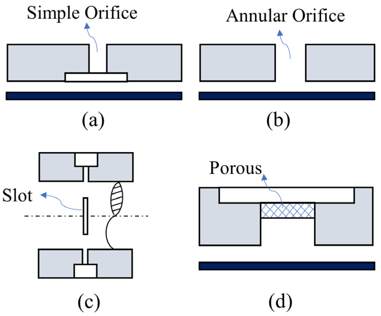
3.3.1. Introduction of Restrictors
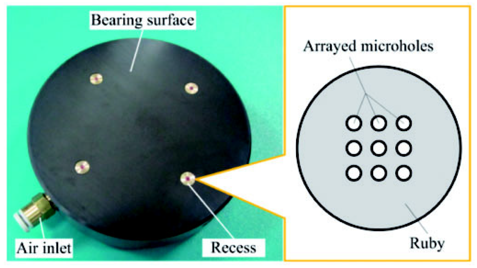
The restrictors in ATBs are mainly classified into four types: orifice restrictors, porous restrictors, annular restrictors, and slot restrictors, as shown in Figure 8 [61]. The orifice restrictor and annular restrictor are the most common types. The annular restrictor (or called the inherently compensated restrictor) is formed by the feed hole. The orifice restrictor is formed with a feed pocket. The orifice is produced with a twist drill and its diameter commonly ranges from 0.15 to 0.4 mm.
  • Micro feed holes
Recently, with the development of laser beam machining and micro drills, it is possible to manufacture feed holes with less than 0.1 mm diameter. The use of micro holes is beneficial to improving the performance of aerostatic bearings. There are two main reasons for adopting micro-holes:
  • The pressure can be improved, and the gas flow can remain stable. The load capacity of the bearing is enhanced.
  • A restricted area independent of the gas clearance is formed.
Aerostatic thrust bearings with micro holes show great potential in improving static performance. Fan, K. C. fabricated an aerostatic bearing using microfabrication technology [33]. The configuration of the several different forms is shown in Figure 9a, and the number of holes is 25,100 and 400, respectively. The surface pressure distribution of the bearing with 25 micro holes is shown in Figure 9b. The cross-sectional area of each micropore is 30 μm2. The gas film pressure is symmetrically distributed. The pressure in the central region is relatively high, showing a diamond distribution. Aerostatic thrust bearings with micro holes have a smooth and uniform pressure distribution. The load capacity has been greatly improved. Miyatake, M. [62] conducted research on small feed holes of less than 0.05 mm diameter with CFD and DFM models. The results indicated that higher stiffness could be obtained by adopting micro feed holes. Belforte, G. [63] investigated the static performance of ATBs with micro feed holes of less than 0.1 mm diameter. The results showed that the load capacity and stiffness of the aerostatic bearings can be optimized by modifying the number and diameter of aerostatic bearings. In order to reduce the nano-scale vibration of aerostatic bearings, Chen, X. D. [64] proposed a novel design scheme for an array micro hole restrictor (AMR). Different from the traditional orifice restrictor, the AMR had uniformly distributed micron-sized holes distributed in the form of arrays, so that the total restricted area was the same as the single-hole restrictor. For a more uniform aperture, AMRs were manufactured with laser drilling technology.
2.
Multi-orifice series
Compared with the traditional orifice-type restrictor, the static performance of the bearing can be improved by adopting the multi-orifice type restrictor. Zheng, Y. Q. proposed a novel pocket orifice-type restrictor with multi-orifice series [65]. The aerostatic bearings with this restrictor had higher maximal bearing stiffness than the traditional bearings. The bearing stiffness increased by 11% with the restrictor of four sub-orifices in the series.
3.
Multi-loop Coupling Pocket
Yu, J. [66] proposed an aerostatic bearing with a double-loop coupling pocket and studied the performance of this bearing. It was found that this type of aerostatic bearing had a higher static load capacity, which provided practical guidance for the design of high-performance aerostatic bearings.

3.3.2. Introduction of Surface Structures

The static performance of the ATBs is not only closely related to the type of restrictor but also the surface structure. Scholars have found that the static performance of bearings can be improved by changing the surface profile of ATBs. Among these surface structures, the most widely used is the pressure-equalizing groove structure [67,68], as depicted in Figure 10. The studies of surface structures are introduced separately below.
4.
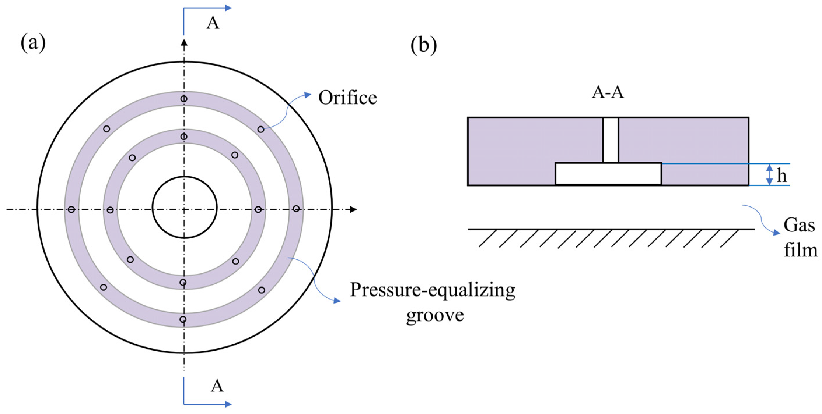
Pressure-equalizing Grooves
Compared with the traditional ATBs, the static performance of ATBs with pressure-equalizing grooves has been greatly improved. Qiao, Y. J. investigated the static performance of aerostatic bearings with trapezoidal pressure-equalizing grooves. The load capacity of the bearing was enhanced by 18% [67]. Zhao, X. L. designed an aerostatic bearing with an elastic equalizing pressure groove. The bearing stiffness was enhanced by 59% compared to bearings without equalizing pressure grooves [68]. Yan, R. Z. carried out numerical simulations on the shapes of pressure-equalizing grooves and studied the static performance of bearings [69]. Six kinds of pressure-equalizing grooves were compared, including the line-shape, the extended-shape, the S-shape, the oblong-shape, the X-shape, and the reticular-shape. The load capacity and stiffness of the bearings can be greatly improved after optimizing the structure of the pressure-equalizing groove, and the pressure-averaging effect can be strengthened. Among the six shapes of pressure-equalizing groove, the reticular shape had the best static performance.
5.
Concave surface texture
The concave surface texture can also improve the static performance of ATBs. Colombo, F. presented an investigation of concave surfaces on the static performance of aerostatic bearings numerically [70]. The results showed that concave aerostatic pads exhibited a higher stiffness than flat aerostatic pads.

4. Advances in Dynamic Performance

4.1. Parametric Research and Optimization

The dynamic performance of aerostatic bearings is related to bearing types, restrictor types, and corresponding operating conditions. A lot of research has been conducted by scholars on the dynamic performance of bearings. Bhat, N. studied the dynamic performance of a compensated flat pad aerostatic bearing, as shown in Figure 11 [39]. When the thickness of the gas film gap was relatively large (greater than 20 μm), negative damping was observed. There was no negative stiffness with the variation of gap height. At low perturbation frequencies, the stiffness coefficient maintained a low constant value. The damping coefficient decreased at a larger gap height. At high perturbation frequencies, the stiffness coefficient increased with higher gap height. The damping coefficient gradually approached zero.
Other detailed research contents are listed in Table 2. From the presented literature, research on the dynamic performance of ATBs is still focused on the dynamic stiffness damping coefficient and stability analysis. Stability analysis mainly includes dynamic response analysis, vibration signal analysis, air hammer phenomena, and so on. With the development of computer technology, the numerical simulation methods and experiment methods of ATBs have become more abundant. At present, more attention is placed on the annular restrictor type and orifice restrictor type. Research on the porous restrictor type and other types is relatively less.

4.2. Structure Improvement

4.2.1. Optimizations of Restrictors

In the study of restrictor optimization, an array of micro-orifice restrictor (AMR) was proposed in the literature [64], as shown in Figure 12. Through fluid dynamics analysis, the transient flow characteristics of aerostatic bearings with an AMR and conventional restrictors were studied. The vibration intensity of the bearing was tested experimentally, which verified the effectiveness of the auto-disturbance rejection method. Under the condition of constant bearing capacity and stiffness, the vortex shedding of the recess can be effectively suppressed by the AMR. The bearing vibration can be effectively reduced.

4.2.2. Structural Optimization

The optimization of the bearing structure is a key step to improving the dynamic performance of ATBs. Aoyama, T. studied the vortex flow in the bearing clearance numerically with a rounded corner near the outlet of the orifice restrictor [89]. The results showed that vortex flow caused small vibrations in aerostatic guideways. The proposed geometrical arrangements can effectively suppress small vibrations. Feng, K. proposed several novel orifice structures of the aerostatic bearing, including the round hole bearing (RHB), inclined hole bearing (IHB), and arc hole bearing (AHB) [90]. Both theoretical predictions and experimental tests showed that changing the orifice structure can significantly reduce pressure fluctuations and improve the stability of the bearing. Among the above bearings, the AHB had the best performance and vortices were extremely small in the recess. The flow field disturbance structure (FFDS) of the aerostatic thrust bearing was designed to change the microscopic flow field inside the bearing. The influence of the flow field disturbance on the micro-vibration was analyzed by the experiment method. The gas flow characteristics of the local field near the outlet of the orifice were greatly optimized due to the flow field disturbance structure. The pulsating pressure on the bearing surface was significantly reduced. The micro-vibration of the bearing with the flow field disturbance structure was suppressed.
Vortices are inevitably caused, due to the fixed flow channels from the feed pocket to the bearing outlet for pressurized gas. The back-flow channels connecting the recess and low-pressure region inside the bearing clearance were designed to provide an additional channel for pressurized gas to be exhausted into the atmosphere [91]. The simulation results showed that the back channels can prevent gas from depositing in the recess. The vortex was greatly eliminated. The bearing stiffness and stability of the aerostatic bearings with the back-flow channel increased simultaneously compared to traditional ATBs.

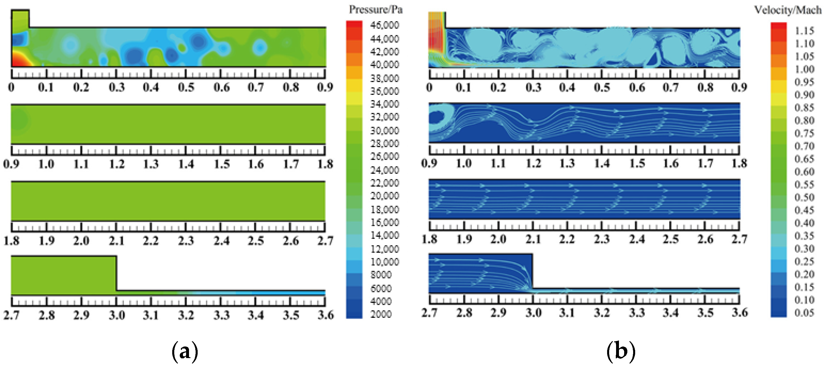
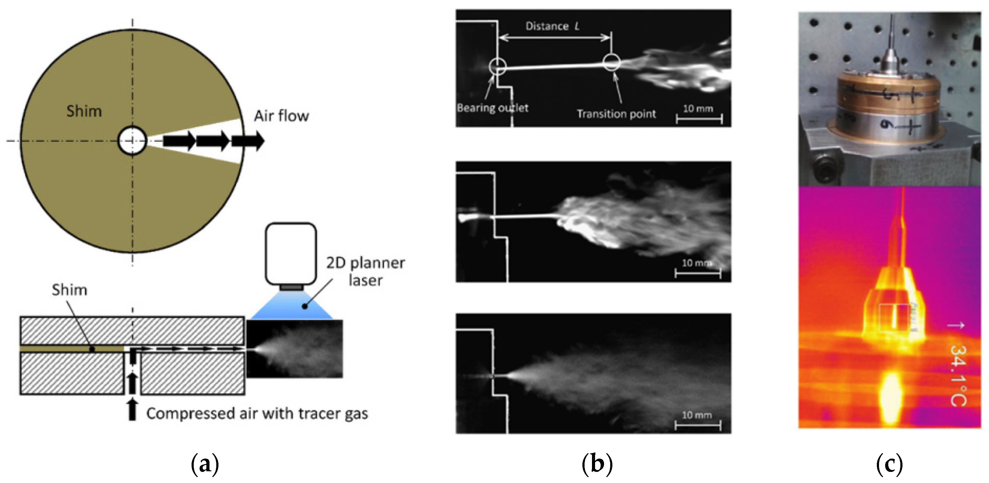
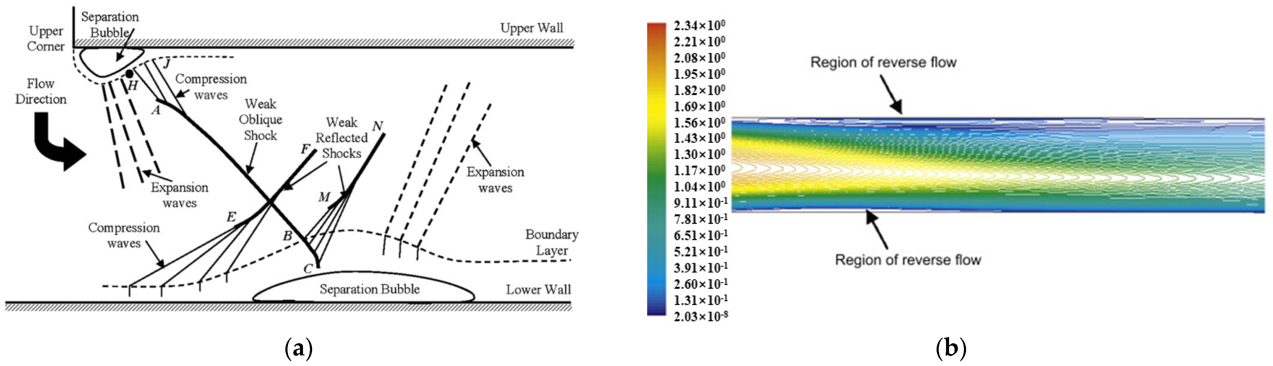
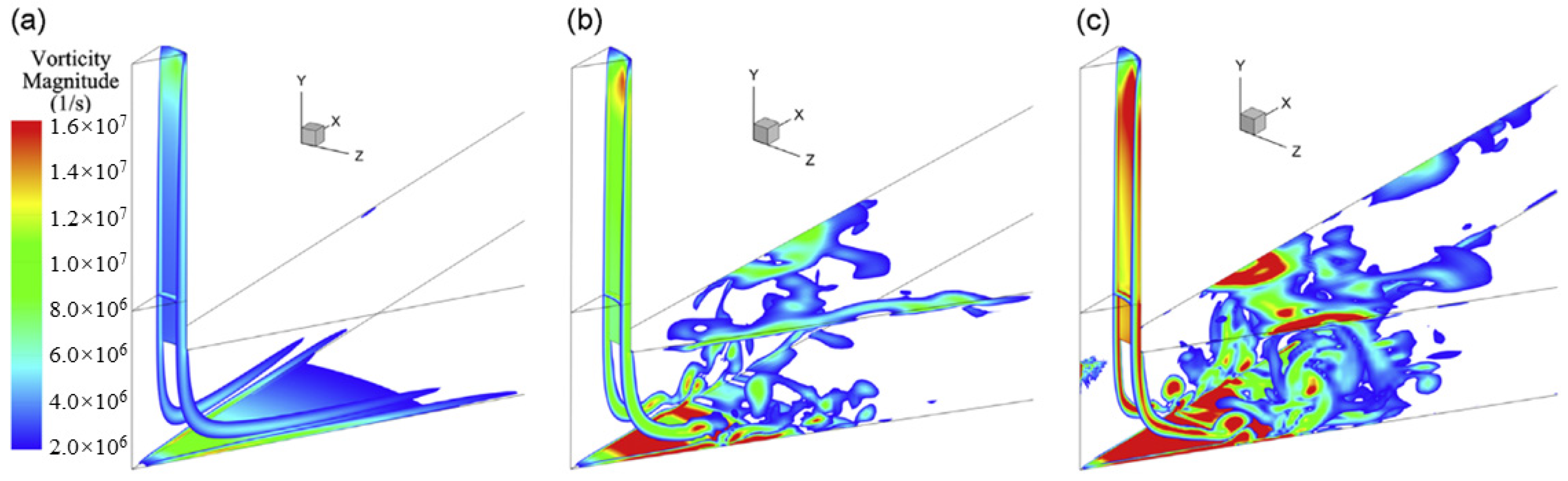
4.3. Flow Characteristics of ATBs

The performance of ATBs is closely related to the gas flow characteristics. It is necessary to investigate flow characteristics from a microscopic perspective. Kawai, T. found that aerostatic bearings inherently have small vibrations in the order of nanometers. These vibrations have a very negative impact on the accuracy and stability of the bearing [92]. To study the mechanism of this phenomenon and suppress the harmful vibration, a more accurate and real-time solution of the flow field needs to be obtained. Chen, X. D. applied RANS simulation to the research. The numerical results validated adequate accuracy in predicting flow characteristics [93]. Yoshimoto, S. investigated the flow characteristics of a circular ATB by solving the Navier–Stokes equations directly [30]. Eleshaky solved the Navier–Stokes equation for the three-dimensional turbulent flow in a circular ATB by RANS simulation [94]. The results showed that the pressure drop phenomenon was caused by the interaction between compression waves and the boundary layer, as depicted in Figure 13. The pressure recovered due to the flow separation at the upper wall. The flow state turned from laminar to turbulence in the region where rapid pressure recovery occurred. Zhu, J. C. applied the large eddy simulation to investigate the transient flow field and the vortex shedding phenomenon in ATBs [95], as shown in Figure 14. Although many investigations have been carried out on various phenomena in the flow field of ATBs, there has not been a consensus on the mechanisms of the flow characteristics in ATBs.

4.4. Pneumatic Hammer Phenomenon

The pneumatic hammer is a high-frequency vibration phenomenon when the bearing is in an abnormal working state [96]. It was found that pneumatic hammer may occur under certain working conditions. As a result, the aerostatic bearing will become unstable and fail. In the bearing design process, static and dynamic characteristics are difficult to take into account at the same time. When the static performance is strengthened, the air pneumatic hammer is more obvious [6]. Dynamic stability is an additional design criterion for bearing design optimization [41]. Talukdar, H. M. conducted an experimental study on pneumatic hammer in aerostatic bearings [97]. Various influencing factors affecting pneumatic hammer were studied, including the depth of the supply recess, the diameter of the orifice, and the bearing mass. The experimental results show that pneumatic hammer can be greatly avoided when the bearing operates under low supply pressure, high load conditions, a small supply hole, and appropriate external damping. Liu et al. analyzed the mechanism of the pneumatic hammer of the air bearing slider [76]. The vibration equation based on the mathematical model of the aerostatic slider was established, and the stability discriminant of the aerostatic slider was obtained. In addition, effective measures to prevent pneumatic hammer vibration were proposed, including reducing the volume of the air chamber, improving the flatness and parallelism of the rail plane, controlling the air support pressure, etc. Considering the delay effect, Zheng, Y. Q. [84] studied the pneumatic hammer phenomenon of the single-pad aerostatic thrust bearing. The combination of air compressibility and volume effect led to the delay of the pocket pressure variation, which led to the delay of the bearing force change. In the larger film thickness region, the delay of the bearing force variation resulted in negative bearing damping, which led to pneumatic hammer. Wu, Y. K. revealed the mechanism of the pneumatic hammer by analyzing the molecular kinetic energy and phase difference between the variations of air film thickness and the load capacity of bearing [98]. The results showed that pneumatic hammer vibration tended to occur when the mass and supply gas pressure were greater than a critical value.

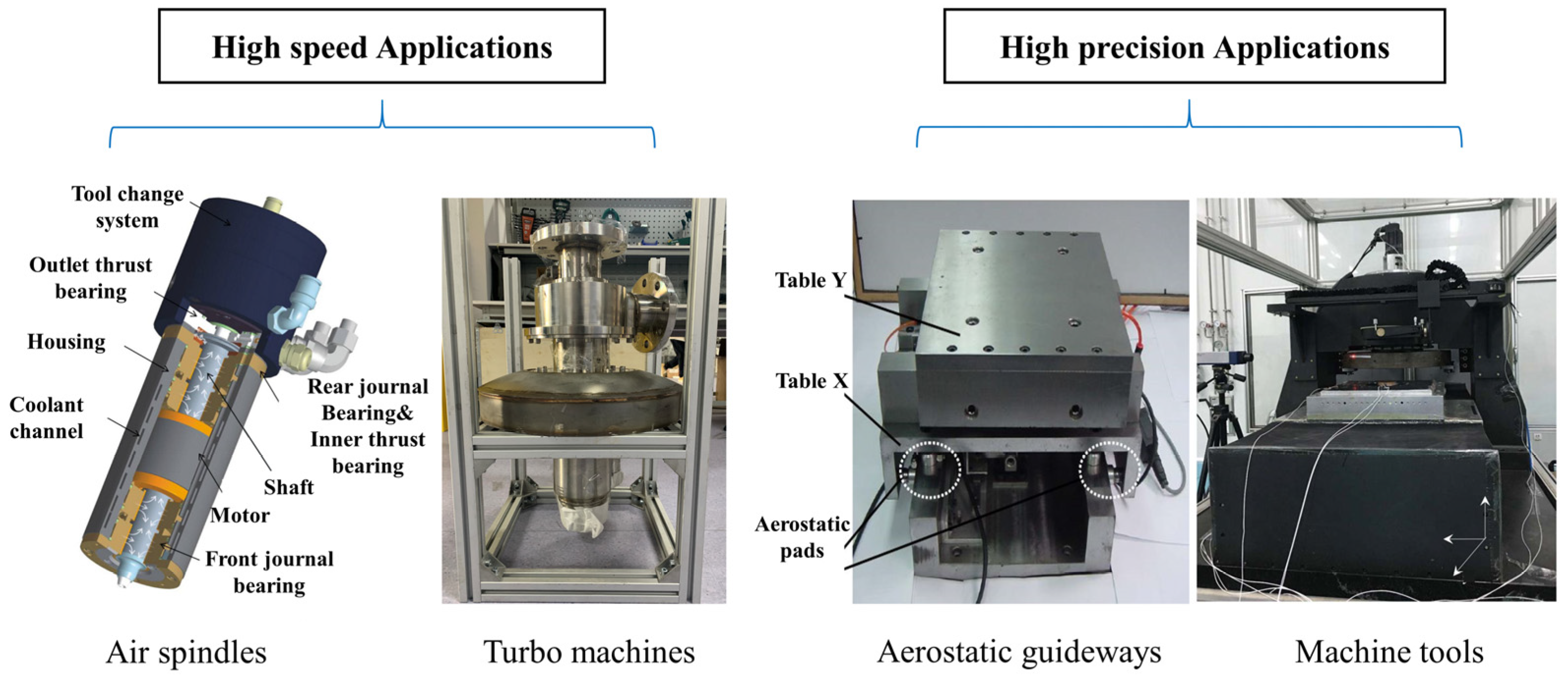
5. The Applications of ATBs

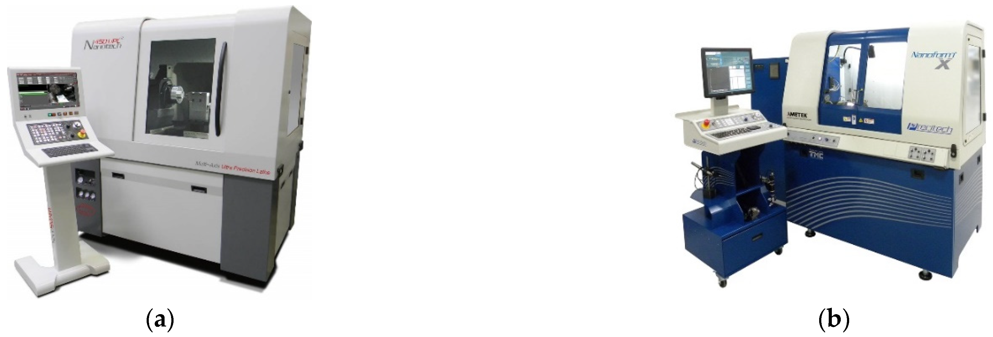
5.1. High Precision Applications

High-precision applications using ATBs mainly include precision machine tools and precision flotation equipment. A large number of mature products have been developed and produced. Moore and Precitch in the United States, Fanuc in Japan, the Loxham Precision Company, Cranfield University in the United Kingdom, the Harbin Institute of Technology in China, and other institutions have developed a variety of high-precision machine tools and mature commercial products.
The Nanotech 250 UPL and Nanotech 450 UPL ultra-precision machine tools were developed by the Moore company, adopting impact-resistant air bearing spindles, as shown in Figure 15 [99,100]. The motion accuracy of machine tools is no more than 12.5 nm at 10 krpm. Precitch ‘s Nanoform X small-frame diamond lathe adopts HS150 and HS75 spindles [101], as shown in Figure 15. The surface roughness of the workpiece is less than 1 nm. The axial stiffness of the HS75 spindle is 105 N/μm. The maximum speed of this working spindle is 18 krpm. Axial/radial motion accuracy is less than 20 nm. The axial stiffness of the HS150 spindle is 230 N/μm. The maximum working speed is 10 krpm. Axial/radial motion accuracy is less than 15 nm. Fanuc has successfully developed a ROBONANO α-0iB five-axis ultra-precision nanomachine [102]. This machine tool is supported by the aerostatic bearing, and the rotation accuracy can reach 0.05 μm. Both the B-axis and C-axis can achieve 360-degree continuous rotation. Loxham [103] has developed an Ultra precision six-axis ultra-precision machine, named μ6. The guideway system is supported by ATBs. The surface roughness is less than 5 nm during turning cutting and less than 10 nm during micro washing.
In addition, study on precision machine tools has been carried out by many research institutions. A three-axis ultra-precision machine tool has been successfully developed by the Tokyo Institute of Technology [104,105], named ANGEL. A new air bearing platform is applied in this machine, and the Z axis is supported by the ATB. The max machined workpiece size is 230 mm × 230 mm × 70 mm. Groove machining with a precision of 20 nm can be realized. National Cheng-Kung university [5] has developed a pneumatic servo table. The sliding guideway is supported by the ATB. The positioning accuracy of the platform can reach 0.04 μm. A small ultra-precision milling machine for micro parts has been developed by Brunel University of the UK [106,107], named Ultramill. Both the spindle and the linear guideway are supported by aerostatic bearings. The motion accuracy of the linear axis of the machine tool is less than 1 μm. The rotation accuracy of the turntable is less than 1′′ (1/3600 degree), and the motion accuracy of the other rotation axis is less than 10′′. For microgroove machining based on the diamond tool, surface roughness can reach 10 nm and straightness error can reach 0.28 μm/40 mm. The Beijing Institute of Aeronautical Precision Machinery [108] has successfully developed an ultra-precision lathe, named Nanosys-300. The aspheric machining accuracy is between 0.3 and 0.5 μm, and surface roughness is less than 0.01 μm. The Institute of Mechanical Manufacturing Technology, Chinese Academy of Sciences [108] has developed an aerostatic lathe spindle. Two aerostatic journal bearings and a thrust bearing are integrated to support the spindle. The roundness of the cutting brass (H62) parts is less than 0.1 μm, and the surface roughness can reach 0.03 μm. Cranfield University [109] has developed a six-axis ultra-precision machine tool, named Integ-μ4. A self-developed porous ATB is adopted in this machine. It has a linear motion resolution of 1 nm and a rotational motion resolution of less than 1 × 10⁻⁸ rad. The dynamic stiffness of this machine is extremely high. A variety of complex shapes of hard and soft materials can be processed. The maximum machined workpiece size is 50 mm × 50 mm × 50 mm, and the machining accuracy can reach the sub-micron level. The Harbin Institute of Technology [110] has developed an ultra-precision machine tool, named HCM-1. Ultra-precision ATBs of jade materials are used to support this machine tool. The maximum circumferential machining diameter can reach 1200 mm. The surface shape accuracy is 2 μm, and the surface roughness can reach 4 nm.

5.2. High-Speed Applications

A typical machine of high-speed applications using ATBs is the turboexpander. In the development of high-speed turboexpanders, the Air Liquid Company, Xi’an Jiaotong University, the Technology Institute of Physics and Chemistry, the Chinese Academy of Science, and other institutions have accumulated profound technical expertise. A lot of research has been conducted on air turboexpanders, hydrogen turboexpanders, and helium turboexpanders using ATBs.
Helium turboexpanders produced by Air Liquid Company have been used in many large scientific devices, such as the tokamak device KSTAR of the Korean National Fusion Research Center (NFRC), and the International Thermonuclear Experimental Reactor (ITER). The 9 kW @ 4.5 K helium refrigerator of KSTAR was equipped with six TC4-500 and TC5-500 helium turboexpanders supported by ATBs [111]. Each of ITER’s 65 kW @ 4.5 K helium refrigerators was equipped with three TC-4 and one TC-5 turboexpander supported by ATBs [112]. The power of three TC-4 turboexpanders is 15, 13, and 11 kW, respectively. The power of the TC-5 turboexpander is 11 kW. The efficiency of all the turboexpanders is greater than 74%. The Creare company in the United States has been working on research for a two-phase helium turbine expander [113]. A helium expander has been designed with a length of 365 mm, a diameter of 150 mm, and a weight of approximately 17 kg. The rotor is supported by two aerostatic journal bearings and one ATB. This turboexpander has been successfully applied in a small helium liquefaction device. The expander works safely in the two-phase region for more than 7500 h. The rotation speed is 354 krpm, with a flow rate of 43 g/s. The isentropic efficiency is about 63%, and the liquefaction is 84 L/h. The Technology Institute of Physics and Chemistry of The Chinese Academy of Science has successfully developed a helium turbine expander. The wheel diameter of the turboexpander is 35 mm, and the brake wheel diameter is 60 mm. Aerostatic thrust bearings have been applied to support the shaft. During testing, the outlet temperature of the helium turboexpander has reached 15.4 K. The maximum cooling capacity is 2.2 kW, and the adiabatic efficiency exceeds 72% [114].
Xi’an Jiaotong University has also conducted a lot of research on turboexpanders. A helium turboexpander supported by ATBs was developed for the space environment simulator KM6 in the late 1990s [115]. The working wheel diameter was 35 mm, and the brake fan wheel diameter was 60 mm. In the low-temperature air environment test, the highest speed reached 127 krpm, and adiabatic efficiency was 68%. While the outlet temperature was 12.8 K, the efficiency of the turboexpander could reach 75%. The maximum cooling capacity was close to 2 kW. In addition, a series of hydrogen and helium turboexpanders have been developed recently [116]. To meet the requirements of axial load, ATBs have been applied as thrust bearings in these hydrogen and helium turboexpanders, as shown in Figure 16. The power of the hydrogen turboexpanders is 20~40 kW. The helium turboexpander is 39.7 kW with a rotation speed of 74.5 krpm. In the air environment test, the rotation speed of the helium turboexpander can reach 60 krpm, and the amplitude is less than 0.023 μm.

6. The Development Trends of ATBs

Aerostatic thrust bearings are widely used in many high-tech fields. The research on ATBs is deepening, and many advances have been achieved. However, there are still some challenges with ATBs. More effort should be put into the study of ATBs.
1. Due to the low viscosity of the gas, the bearing capacity and stiffness of ATBs are much lower than oil bearings. These shortcomings limit the further application of ATBs. It is necessary to produce ATBs with greater stiffness and greater load capacity. In the theoretical analysis of ATBs, some traditional assumptions and neglected factors must be considered. For example, in the case of low gas film thickness, the influence of factors such as surface roughness and the mean free path of gas molecules must be considered. In the case of high-speed flow, the assumption of isothermal gas flow, the influence of gas inertial effects, shock waves, and turbulent flow effects, etc., must be carefully analyzed. In addition, under the guidance of theoretical analysis, the design level of the bearing should be continuously improved. The manufacturing process and the machining accuracy of ATBs should be enhanced. The use of modern and more precise experimental methods is also critical. It is necessary to combine theoretical analysis with experimental analysis to design ATBs with higher load capacity and higher stiffness.
2. In addition to air, nitrogen, hydrogen, and helium, other gases are also used in ATBs to meet different working conditions and needs. With the development of hydrogen and helium liquefaction equipment, the application of ATBs using special gas becomes more extensive. There is much research on aerostatic bearings, while the research on aerostatic bearings using special gas is still limited. Due to the flammability and leakage of hydrogen and the scarcity of helium, it is relatively difficult to carry out related experimental research. The relevant experimental data are even more scarce. Due to the unique physical properties of special gases, their flow characteristics, load-carrying characteristics, and the stability performance of ATBs are completely different from traditional air ATBs. Therefore, more effort should be put into the research of ATBs using special gases. In addition, the corresponding protective measures should be taken during experimentation to ensure experiment safety.
3. When gas is used as a lubricating medium, problems such as solidification at low temperature and volatilization at high temperature of oil are completely overcome. Aerostatic bearings are suitable for high- and low-temperature environments. There are many studies of ATBs in normal temperature and low-temperature environments, while the research in high-temperature environments is relatively less. In a high-temperature environment, the effects of high temperature on gas properties should be considered. In addition, the influence of high temperature on the thermal deformation of the bearings should be considered. The gas film thickness changes due to the thermal deformation of the bearing, which will affect the bearing performance.

7. Conclusions and Discussions

In this paper, the research developments of ATBs are summarized from several aspects: theoretical models and experimental methods, static performance, dynamic performance, and the applications of ATBs. In addition, the development trends of ATBs are discussed. Based on the above analysis, the following conclusions can be drawn:
6.
Accurate theoretical models and experimental methods.
The flow in aerostatic bearings is very complex. There are various phenomena such as turbulence, supersonic flow, velocity slip effect, pneumatic hammer, and shock waves. These factors have a non-negligible impact on bearing performance. There are still some challenges in theoretical calculation. The multiple physical fields need to be coupled with the increasing complexity of the bearing system. More refined theoretical models are required to ensure accuracy in the design and verification of ATBs. Experimental technology plays an important role in studying bearing performance, verifying theoretical models, and exploring phenomenon mechanisms. The experimental methods applied to ATBs are limited by tiny bearing clearances. The tedious experimental equipment and test process also limit the performance measurement of ATBs. Thus, more accurate and advanced experimental test methods are necessary.
7.
High-performance ATBs with large stiffness and load capacity.
The applications of ATBs are affected by some demerits, such as low load capacity and stiffness. The stiffness and load capacity of ATBs are far less than with oil bearings. The development of high-speed machinery and high-precision machinery has demanded higher requirements for the performance of ATBs. Therefore, it is urgent to develop high-performance ATBs with significant stiffness and load capacity.
8.
The applications of ATBs in special conditions.
9.
At present, there is still limited literature on the study of ATBs working in extreme-temperature environments, and the adopting of special gases as a lubricating medium. With increasing applications of ATBs under special conditions, it is necessary to spend more research time on ATBs adopting special gases, and ATBs under extreme-temperature conditions. At the same time, the influence of extreme-temperature conditions and special gases on bearing performance should be considered.
10.
Pneumatic hammer of ATBs.
With the development of ATB technology, theory study has become more and more evolved. The pneumatic hammer is a key problem in the study of the dynamic performance of ATBs, which can easily lead to the instability or failure of ATBs. The pneumatic hammer has been studied from different perspectives. Corresponding research results have been obtained. However, there is still no consistent theoretical explanation for the pneumatic hammer. Further in-depth research is needed on the study of the pneumatic hammer.

Author Contributions

Literature investigation, Q.Z., M.Q.; supervision, T.L., Y.H. and S.C.; validation, Q.Z. and T.L.; writing—original draft, Q.Z.; writing—review and editing, Q.Z. and T.L. All authors have read and agreed to the published version of the manuscript.

Funding

This project was funded by the National Key R&D Program of China (2019YFB1504600) and the Youth Innovation Team of Shaanxi Universities.

Institutional Review Board Statement

Not applicable.

Informed Consent Statement

Not applicable.

Data Availability Statement

Not applicable.

Conflicts of Interest

The authors declare no conflict of interest.

References

  1. Gao, Q.; Lu, L.H.; Chen, W.Q.; Wang, G.L. Optimal design of an annular thrust air bearing using parametric computational fluid dynamics model and genetic algorithms. Proc. Inst. Mech. Eng. Part J-J. Eng. Tribol. 2018, 232, 1203–1214. [Google Scholar]
  2. Gao, S.Y.; Cheng, K.; Ding, H.; Fu, H.Y. Multiphysics-based design and analysis of the high-speed aerostatic spindle with application to micro-milling. Proc. Inst. Mech. Eng. Part J J. Eng. Tribol. 2015, 230, 852–871. [Google Scholar]
  3. Wang, C.; Cheng, K.; Rakowski, R.; Soulard, J. An experimental investigation on ultra-precision instrumented smart aerostatic bearing spindle applied to high speed micro-drilling. J. Manuf. Process. 2018, 31, 324–335. [Google Scholar]
  4. Zhou, K.M.; Li, S.F.; Zhao, K.; Lin, H.H.; Zhang, Z.; Chen, L.; Hou, Y.; Chen, S.T. Efficiency control of the cooling-down process of a cryogenic helium turbo-expander for a 2 t/d hydrogen liquefier. Int. J. Hydrog. Energy 2022, 47, 29794–29807. [Google Scholar]
  5. Tsai, M.H.; Hsu, T.Y.; Pai, K.R.; Shih, M.C. Precision position control of pneumatic servo table embedded with aerostatic bearing. J. Syst. Des. Dyn. 2008, 2, 940–949. [Google Scholar]
  6. Chen, D.J.; Bian, Y.H.; Fan, J.W. Experiments and Identification of the Unbalance of Aerostatic Guideways on the Micro-Scale. Sensors 2014, 14, 4416–4427. [Google Scholar]
  7. Ding, J.G.; Chang, Y.; Chen, P.; Zhuang, H.; Ding, Y.Y.; Lu, H.J.; Chen, Y.H. Dynamic modeling of ultra-precision fly cutting machine tool and the effect of ambient vibration on its tool tip response. Int. J. Extrem. Manuf. 2020, 2, 025301. [Google Scholar]
  8. Chen, D.; Fan, J.; Zhang, F. Diagnosis of gas fluctuations of aerostatic guideway. Measurement 2011, 44, 434–444. [Google Scholar]
  9. Colombo, F.; Lentini, L.; Raparelli, T.; Trivella, A.; Viktorov, V. Dynamic characterisation of rectangular aerostatic pads with multiple inherent orifices. Tribol. Lett. 2018, 66, 133. [Google Scholar]
  10. Gao, Q.; Qi, L.Z.; Gao, S.Y.; Lu, L.H.; Song, L.Y.; Zhang, F.H. A FEM based modeling method for analyzing the static performance of aerostatic thrust bearings considering the fluid-structure interaction. Tribol. Int. 2021, 156, 106849. [Google Scholar]
  11. Mori, H.A. Theoretical investigation of pressure depression in externally pressurized gas-lubricated circular thrust bearings. J. Basic Eng. 1961, 83, 201–208. [Google Scholar]
  12. Stahler, A.F. Further comments on the pressure depression effect in externally pressurized gas-lubricated bearings. ASLE Trans. 1964, 7, 366–376. [Google Scholar]
  13. Moller, P.S. Radial flow without swirl between parallel disks having both supersonic and subsonic regions. J. Basic Eng. 1966, 88, 147–154. [Google Scholar]
  14. Salem, E.; Kamal, W. Effect of recess geometry on shock-wave formation in circular gas-bearings. WEAR 1978, 46, 351–366. [Google Scholar]
  15. Li, Y.; Wan, X.; Li, X.L. Microvibration suppression of an aerostatic thrust bearing adopting flow field disturbance structure. Adv. Mech. Eng. 2017, 9, 1–9. [Google Scholar]
  16. Kassab, S.Z. Empirical correlations for the pressure depression in externally pressurized gas bearings. Tribol. Int. 1997, 30, 59–67. [Google Scholar]
  17. Majumdar, B.C. Externally pressurized gas-bearings a review. Wear 1980, 62, 299–314. [Google Scholar]
  18. Yang, J.Y.; Shih, Y.D. The effects of velocity slip on externally pressurized gas porous thrust-bearings. Wear 1991, 150, 169–176. [Google Scholar]
  19. Mitsuya, Y.T. Nano-technologies for head-medium interface in magnetic disk storage. In Proceedings of the 1997 International Symposium on Micromechatronics and Human Science, Nagoya, Japan, 5–8 October 1997; pp. 27–32. [Google Scholar] [CrossRef]
  20. Hsia, Y.T.; Domoto, G.A. An experimental investigation of molecular rarefaction effects in gas lubricated bearings at ultra-low clearances. J. Lubr. Technol. 1983, 105, 120–129. [Google Scholar]
  21. Chen, D.J.; Han, J.H.; Huo, C.; Fan, J.W.; Cheng, Q. Effect of gas slip on the behavior of the aerostatic guideway. Ind. Lubr. Tribol. 2017, 69, 447–454. [Google Scholar]
  22. Chen, D.J.; Kong, S.; Liu, J.F.; Fan, J.W. Influence of micro-scale velocity slip on the dynamic characteristics of aerostatic slider. Ind. Lubr. Tribol. 2021, 73, 120–125. [Google Scholar]
  23. Aguirre, G.; Al-Bender, F.; Van Brussel, H. A multiphysics model for optimizing the design of active aerostatic thrust bearings. Precis. Eng. -J. Int. Soc. Precis. Eng. Nanotechnol. 2010, 34, 507–515. [Google Scholar]
  24. Lu, L.H.; Zhao, Z.Q.; Liang, Y.C.; Zhang, L.J. Calculation and analysis for stiffness of the thrust aerostatic bearing of ultra-precision machine tools. In Proceedings of the 5th International Symposium on Advanced Optical Manufacturing and Testing Technologies: Advanced Optical Manufacturing Technologies, Dalian, China, 26–29 April 2010. [Google Scholar]
  25. Lu, L.H.; Chen, W.Q.; Wu, B.; Gao, Q.; Wu, Q.H. Optimal design of an aerostatic spindle based on fluid-structure interaction method and its verification. Proc. Inst. Mech. Eng. Part J-J. Eng. Tribol. 2016, 230, 690–696. [Google Scholar]
  26. Lu, L.H.; Gao, Q.; Chen, W.Q.; Liu, L.; Wang, G.L. Investigation on the fluid-structure interaction effect of an aerostatic spindle and the influence of structural dimensions on its performance. Proc. Inst. Mech. Eng. Part J-J. Eng. Tribol. 2017, 231, 1434–1440. [Google Scholar]
  27. Maamari, N.; Krebs, A.; Weikert, S.; Wild, H.; Wegener, K. Stability and dynamics of an orifice based aerostatic bearing with a compliant back plate. Tribol. Int. 2019, 138, 279–296. [Google Scholar]
  28. Yan, R.Z.; Wang, L.Y.; Wang, S.Z. Mechanical research on aerostatic guideways in consideration of fluid-structure interaction. Ind. Lubr. Tribol. 2020, 72, 285–290. [Google Scholar]
  29. Gao, Q.; Chen, W.Q.; Lu, L.H.; Huo, D.H.; Cheng, K. Aerostatic bearings design and analysis with the application to precision engineering: State-of-the-art and future perspectives. Tribol. Int. 2019, 135, 1–17. [Google Scholar]
  30. Yoshimoto, S.; Yamamoto, M.; Toda, K. Numerical calculations of pressure distribution in the bearing clearance of circular aerostatic thrust bearings with a single air supply inlet. J. Tribol. 2006, 129, 384–390. [Google Scholar]
  31. Belforte, G.; Raparelli, T.; Viktorov, V.; Trivella, A. Discharge coefficients of orifice-type restrictor for aerostatic bearings. Tribol. Int. 2007, 40, 512–521. [Google Scholar]
  32. Belforte, G.; Raparelli, T.; Trivella, A.; Viktorov, V.; Visconte, C. CFD Analysis of a simple orifice-type feeding system for aerostatic bearings. Tribol. Lett. 2015, 58, 25. [Google Scholar]
  33. Fan, K.C.; Ho, C.C.; Mou, J.I. Development of a multiple-microhole aerostatic air bearing system. J. Micromech. Microeng. 2002, 12, 636–643. [Google Scholar]
  34. Bhat, N.; Barrans, S.M. Design and test of a Pareto optimal flat pad aerostatic bearing. Tribol. Int. 2008, 41, 181–188. [Google Scholar]
  35. Belforte, G.; Colombo, F.; Raparelli, T. Static behaviour of air plane pads: Comparison between different feeding solutions. Stroj. Vestn.-J. Mech. Eng. 2010, 56, 261–267. [Google Scholar]
  36. Belforte, G.; Colombo, F.; Raparelli, T.; Trivella, A.; Viktorov, V. Comparison between grooved and plane aerostatic thrust bearings: Static performance. Meccanica 2011, 46, 547–555. [Google Scholar]
  37. Zhou, Y.J.; Chen, X.D.; Cai, Y.K.; Chen, H.; Han, B. Measurement of gas pressure distribution in aerostatic thrust bearings using pressure-sensitive film. Tribol. Int. 2018, 120, 9–15. [Google Scholar]
  38. Vahdati, M.; Shokuhfar, A.; Bagheri, M. The influence of external load and air pressure on air slide table performance of ultra precision machines in nano machining. Diffus. Solids Liq. 2008, 283–286, 177–182. [Google Scholar]
  39. Bhat, N.; Kumar, S.; Tan, W.; Narasimhan, R.; Tsu Chuin, L. Performance of inherently compensated flat pad aerostatic bearings subject to dynamic perturbation forces. Precis. Eng.-J. Int. Soc. Precis. Eng. Nanotechnol. 2012, 36, 399–407. [Google Scholar]
  40. Cui, H.L.; Wang, Y.; Wang, B.R.; Yang, H.; Xia, H. Numerical simulation and experimental verification of the stiffness and stability of thrust pad aerostatic bearings. Chin. J. Mech. Eng. 2018, 31, 23. [Google Scholar]
  41. Al-Bender, F. On the modelling of the dynamic characteristics of aerostatic bearing films: From stability analysis to active compensation. Precis. Eng. 2009, 33, 117–126. [Google Scholar]
  42. Yoshimura, T.; Hanafusa, T.; Kitagawa, T.; Hirayama, T.; Matsuoka, T.; Yabe, H. Clarifications of the mechanism of nano-fluctuation of aerostatic thrust bearing with surface restriction. Tribol. Int. 2012, 48, 29–34. [Google Scholar]
  43. Andrisano, A.; Maggiore, A. Theoretical and experimental analysis of an externally pressurized porous gas thrust bearing. Tribol. Int. 1978, 11, 285–288. [Google Scholar]
  44. Bhat, N.; Barrans, S.M.; Kumar, A.S. Performance analysis of Pareto optimal bearings subject to surface error variations. Tribol. Int. 2010, 43, 2240–2249. [Google Scholar]
  45. Jeng, Y.R.; Chang, S.H. Comparison between the effects of single-pad and double-pad aerostatic bearings with pocketed orifices on bearing stiffness. Tribol. Int. 2013, 66, 12–18. [Google Scholar]
  46. Chang, S.H.; Jeng, Y.R. A modified particle swarm optimization algorithm for the design of a double-pad aerostatic bearing with a pocketed orifice-type restrictor. J. Tribol.-Trans. ASME 2014, 136, 021701. [Google Scholar]
  47. Huang, T.Y.; Lin, S.C.; Shen, S.C.; Hsu, S.Y. The effect of rotational speed on fluid compressibility and gap pressure of a partially porous aerostatic thrust bearing. Key Eng. Mater. 2015, 642, 311–316. [Google Scholar]
  48. Wang, N.; Chen, H.Y. A two-stage multiobjective optimization algorithm for porous air bearing design. Tribol. Int. 2016, 93, 355–363. [Google Scholar]
  49. Chen, D.J.; Cui, X.X.; Fan, J.W. A prediction and evaluation system of the impact factors on the performance of the aerostatic slider. Robot. Comput.-Integr. Manuf. 2018, 50, 213–221. [Google Scholar]
  50. Lai, T.; Peng, X.Q.; Liu, J.F.; Guan, C.L.; Chen, X.G.; Tie, G.P.; Guo, M. Design optimization of high-precision aerostatic equipment based on orifice restriction. Proc. Inst. Mech. Eng. Part C-J. Mech. Eng. Sci. 2019, 233, 3459–3474. [Google Scholar]
  51. Moradi, M.; Colombo, F.; Raparelli, T.; Trivella, A.; Viktorov, V. Dynamic lumped model of externally pressurized rectangular air bearings. Precis. Eng.-J. Int. Soc. Precis. Eng. Nanotechnol. 2019, 56, 101–112. [Google Scholar]
  52. Zhuang, H.; Ding, J.; Chen, P.; Chang, Y.; Zeng, X.Y.; Yang, H.; Liu, X.B.; Wei, W. Numerical study on static and dynamic performances of a double-pad annular inherently compensated aerostatic thrust bearing. J. Tribol. Trans. ASME 2019, 141, 051701. [Google Scholar]
  53. Colombo, F.; Della Santa, F.; Pieraccini, S. Multi-objective optimisation of an aerostatic pad: Design of position, number and diameter of the supply holes. J. Mech. 2020, 36, 347–360. [Google Scholar]
  54. Bryant, M.R.; Velinsky, S.A.; Beachley, N.H.; Fronczak, F.J. A design methodology for obtaining infinite stiffness in an aerostatic thrust bearing. J. Mech. Transm. Autom. Des.-Trans. ASME 1986, 108, 448–453. [Google Scholar]
  55. Mori, H.; Miyamatsu, Y. Theoretical flow-models for externally pressurized gas bearings. J. Lubr. Technol. 1969, 91, 181–193. [Google Scholar]
  56. Kazimierski, Z.; Trojnarski, J. Investigations of externally pressurized gas bearings with different feeding systems. J. Lubr. Technol. 1980, 102, 59–64. [Google Scholar]
  57. Belforte, G.; Raparelli, T.; Trivella, A.; Viktorov, V.; Visconte, C. Numerical analysis on the supply hole discharge coefficient in aerostatic bearings. In Proceedings of the International Conference on Tribology AITC-AIT, Parma, Italy, 20–22 September 2006; pp. 20–22. [Google Scholar]
  58. Belforte, G.; Raparelli, T.; Viktorov, V.; Trivella, A. Effects of supply hole dimensions and operating conditions on the hole discharge coefficient of an aerostatic bearing. In Proceedings of the third AIMETA International Tribology Conference, Vietri Sul Mare, Salerno, Italy, 18–21 September 2002; pp. 18–20. [Google Scholar]
  59. Belforte, G.; Raparelli, T.; Trivella, A.; Viktorov, V. Identification of discharge coefficients of orifice-type restrictors for aerostatic bearings and application examples. New Tribol. Ways 2011, 359–380. [Google Scholar] [CrossRef] [Green Version]
  60. Renn, J.C.; Hsiao, C.H. Experimental and CFD study on the mass flow-rate characteristic of gas through orifice-type restrictor in aerostatic bearings. Tribol. Int. 2004, 37, 309–315. [Google Scholar]
  61. Wang, Y.F. Gas lubricated Theory and Design Manual of Gas Bearing; China Machine Press: Beijing, China, 1999. [Google Scholar]
  62. Miyatake, M.; Yoshimoto, S. Numerical investigation of static and dynamic characteristics of aerostatic thrust bearings with small feed holes. Tribol. Int. 2010, 43, 1353–1359. [Google Scholar]
  63. Belforte, G.; Colombo, F.; Raparelli, T.; Trivella, A.; Viktorov, V. Experimental analysis of air pads with micro holes. Tribol. Trans. 2013, 56, 169–177. [Google Scholar]
  64. Chen, X.D.; Chen, H.; Zhu, J.C.; Jiang, W. Vortex suppression and nano-vibration reduction of aerostatic bearings by arrayed microhole restrictors. J. Vib. Control 2017, 23, 842–852. [Google Scholar]
  65. Zheng, Y.Q.; Yang, G.W.; Cui, H.L.; Hou, Y. Improving the stiffness of the aerostatic thrust bearing by using a restrictor with multi-orifice series. Proc. Inst. Mech. Eng. Part J-J. Eng. Tribol. 2020, 234, 1881–1891. [Google Scholar]
  66. Yu, J.; Fang, B.; Guo, T.T.; Li, D.S.; Zhang, W. Design of aerostatic bearing restrictor with multi-loop coupling pocket. In Proceedings of the 6th International Symposium on Precision Engineering Measurements and Instrumentation, Hangzhou, China, 8–11 August 2010; Volume 7544, pp. 232–240. [Google Scholar]
  67. Qiao, Y.J.; Luo, R.; Shi, K.J. Analysis on the Influence for the Sectional Shape of Compound Pressure-equalizing Groove to the Supporting and Bearing Characteristics of Precision Aerostatic Bearing. Appl. Mech. Mater. 2014, 494, 598–601. [Google Scholar]
  68. Zhao, X.L.; Zhang, J.A.; Dong, H.; Fang, Z.; Li, J.N. Numerical simulation and experimental study on the gas-solid coupling of the aerostatic thrust bearing with elastic equalizing pressure groove. Shock Vib. 2017, 2017, 5091452. [Google Scholar]
  69. Yan, R.Z.; Wang, L.Y.; Wang, S.Z. Investigating the influences of pressure-equalizing grooves on characteristics of aerostatic bearings based on CFD. Ind. Lubr. Tribol. 2019, 71, 853–860. [Google Scholar]
  70. Colombo, F.; Lentini, L.; Raparelli, T.; Viktorov, V.; Trivella, A. On the static performance of concave aerostatic pads. In Advances in Mechanism and Machine Science, Proceedings of the 15th IFToMM World Congress on Mechanism and Machine Science, Krakow, Poland, 15-18 July 2019; Springer: Cham, Switzerland, 2019; Volume 73, pp. 3919–3928. [Google Scholar]
  71. Yoshimoto, S.; Kohno, K. Static and dynamic characteristics of aerostatic circular porous thrust bearings (Effect of the shape of the air supply area). J. Tribol.-Trans. ASME 2001, 123, 501–508. [Google Scholar]
  72. Chen, M.F.; Lin, Y.T. Dynamic analysis of the X-shaped groove aerostatic bearings with disk-spring compensator. JSME Int. J. Ser. C-Mech. Syst. Mach. Elem. Manuf. 2002, 45, 492–501. [Google Scholar]
  73. Fan, K.C.; Yen, R.H.; Ho, C.C. Study of a miniature air bearing linear stage system. Mater. Sci. Forum 2009, 505–507, 13–18. [Google Scholar]
  74. Belforte, G.; Colombo, F.; Raparelli, T.; Trivella, A.; Viktorov, V. Study of the static and dynamic performance of rectangular air pads by means of lumped parameters models. In Proceedings of the 11th Biennial Conference on Engineering Systems Design and Analysis ESDA, Nantes, France, 2–4 July 2012. [Google Scholar]
  75. Oiwa, N.; Masuda, M.; Hirayama, T.; Matsuoka, T.; Yabe, H. Deformation and flying height orbit of glass sheets on aerostatic porous bearing guides. Tribol. Int. 2012, 48, 2–7. [Google Scholar]
  76. Liu, Z.; Zhang, M.; Zhu, Y.; Qi, L.S.; Wu, Y.F. Study on generation mechanism and stability analysis for air hammer of air-bearing slider. In Proceedings of the 2014 IEEE International Conference on Mechatronics and Automation, Tianjin, China, 3–6 August 2014; pp. 1405–1410. [Google Scholar]
  77. Gao, S.Y.; Cheng, K.; Chen, S.J.; Ding, H.; Fu, H.Y. CFD based investigation on influence of orifice chamber shapes for the design of aerostatic thrust bearings at ultra-high speed spindles. Tribol. Int. 2015, 92, 211–221. [Google Scholar]
  78. Colombo, F.; Moradi, M.; Raparelli, T.; Trivella, A.; Viktorov, V. Multiple holes rectangular gas thrust bearing: Dynamic stiffness calculation with lumped parameters approach. Adv. Ital. Mech. Sci. 2017, 47, 421–429. [Google Scholar]
  79. Li, Y.F.; Yin, Y.H.; Yang, H.; Liu, X.; Mo, J.; Cui, H.L. Modeling for optimization of circular flat pad aerostatic bearing with a single central orifice-type restrictor based on CFD simulation. Tribol. Int. 2017, 109, 206–216. [Google Scholar]
  80. Chen, D.J.; Han, J.H.; Cui, X.X.; Fan, J.W. Identification and evaluation for the dynamic signals caused by pressure fluctuation of aerostatic slider. Ind. Lubr. Tribol. 2018, 70, 927–934. [Google Scholar]
  81. Federico, C.; Lentini, L.; Terenziano, R.; Andrea, T.; Vladimir, V. A nonlinear lumped parameter model of an externally pressurized rectangular grooved air pad bearing. In Advances in Italian Mechanism Science, Proceedings of the Second International Conference of IFToMM Italy, Cassino, Italy, 2018; Springer: Berlin/Heidelberg, Germany, 2019; Volume 68, pp. 490–497. [Google Scholar] [CrossRef]
  82. Colombo, F.; Lentini, L.; Raparelli, T.; Trivella, A.; Viktorov, V. A lumped model for grooved aerostatic pad. Adv. Serv. Ind. Robot. 2019, 67, 678–686. [Google Scholar]
  83. Ghodsiyeh, D.; Colombo, F.; Lentini, L.; Raparelli, T.; Trivella, A.; Viktorov, V. An infinite stiffness aerostatic pad with a diaphragm valve. Tribol. Int. 2020, 141, 105964. [Google Scholar]
  84. Zheng, Y.Q.; Yang, G.W.; Cui, H.L.; Hou, Y. Pneumatic stability analysis of single-pad aerostatic thrust bearing with pocketed orifice. Proc. Inst. Mech. Eng. Part J-J. Eng. Tribol. 2020, 234, 1857–1866. [Google Scholar]
  85. Li, M.Y.; Hu, Q.; Liu, P.K.; Huang, M. Analysis and optimization of performance under operating condition of thrust aerostatic bearing with vacuum pre-load. Adv. Mech. Des. 2020, 77, 288–301. [Google Scholar]
  86. Colombo, F.; Lentini, L.; Raparelli, T.; Trivella, A.; Viktorov, V. Dynamic behaviour and stability analysis of a compensated aerostatic pad. E3S Web Conf. 2021, 312, 05003. [Google Scholar]
  87. Colombo, F.; Lentini, L.; Raparelli, T.; Trivella, A.; Viktorov, V. Air pad controlled by means of a diaphragm-valve: Static and dynamic behaviour. In Advances in Italian Mechanism Science, Proceedings of the 3rd International Conference of IFToMM Italy, Online; Springer: Cham, Switzerland, 2021; Volume 91, pp. 699–710. [Google Scholar]
  88. Yao, J.H.; Yin, Z.Q.; Chai, N.; Meng, S.T.; Li, Y.L. Design of an eccentric vacuum preloaded aerostatic bearing to improve the lateral stiffness of guideway. Tribol. Trans. 2022, 65, 321–336. [Google Scholar]
  89. Aoyama, T.; Kakinuma, Y.; Kobayashi, Y. Numerical and experimental analysis for the small vibration of aerostatic guideways. CIRP Ann. 2006, 55, 419–422. [Google Scholar]
  90. Feng, K.; Wang, P.; Zhang, Y.J.; Hou, W.J.; Li, W.N.; Wang, J.W.; Cui, H. Novel 3-D printed aerostatic bearings for the improvement of stability: Theoretical predictions and experimental measurements. Tribol. Int. 2021, 163, 107149. [Google Scholar]
  91. Li, W.J.; Wang, G.Q.; Feng, K.; Zhang, Y.C.; Wang, P. CFD-based investigation and experimental study on the performances of novel back-flow channel aerostatic bearings. Tribol. Int. 2022, 165, 107319. [Google Scholar]
  92. Kawai, T.; Ebihara, K.; Takeuchi, Y. Improvement of machining accuracy of 5-axis control ultraprecision machining by means of laminarization and mirror surface finishing. CIRP Ann. 2005, 54, 329–332. [Google Scholar]
  93. Chen, X.D.; He, X.M. The effect of the recess shape on performance analysis of the gas-lubricated bearing in optical lithography. Tribol. Int. 2006, 39, 1336–1341. [Google Scholar]
  94. Eleshaky, M.E. CFD investigation of pressure depressions in aerostatic circular thrust bearings. Tribol. Int. 2009, 42, 1108–1117. [Google Scholar]
  95. Zhu, J.C.; Chen, H.; Chen, X.D. Large eddy simulation of vortex shedding and pressure fluctuation in aerostatic bearings. J. Fluids Struct. 2013, 40, 42–51. [Google Scholar]
  96. Kong, Z.; Tao, J. Pneumatic hammer in aerostatic thrust bearings with single orifice compensation. In Proceedings of the International Symposium on Precision Engineering Measurement and Instrumentation, Chengdu, China, 8–11 August 2012; Volume 8759. [Google Scholar]
  97. Talukder, H.M.; Stowell, T.B. Pneumatic hammer in an externally pressurized orifice-compensated air journal bearing. Tribol. Int. 2003, 36, 585–591. [Google Scholar]
  98. Wu, Y.K.; Li, C.L.; Du, J.J.; Liu, T.; Zuo, X.Y. Pneumatic hammer characteristics of the aerostatic thrust bearing with central orifice and pressure-equalizing groove. Nonlinear Dyn. 2022, 1–22. [Google Scholar] [CrossRef]
  99. The Nanotech 250UPL Ultra-Precision Machine Tools. [EB/OL]. Available online: https://nanotechsys.com/250-upl/ (accessed on 3 October 2022).
  100. The Nanotech 450UPL Ultra-Precision Machine Tools. [EB/OL]. Available online: https://nanotechsys.com/450-upl/ (accessed on 3 October 2022).
  101. Nanoform X Diamond Lathe. [EB/OL]. Available online: https://www.precitech.cn/product/smallframelathesoverview/nanoform-x (accessed on 3 October 2022).
  102. Wu, Y.K. Research on Self-Excited Vibration of Air Hammer of Disk Hydrostatic Gas Thrust Bearing Based on Weak Coupling Method; Harbin Institute of Technology: Harbin, China, 2021. (In Chinese) [Google Scholar]
  103. Ultra Precision 6-Axis Ultra-Precision Machine. [EB/OL]. Available online: https://www.loxhamprecision.com/products/μ6-diamond-turning-machine/ (accessed on 3 October 2022).
  104. Shinno, H.; Yoshioka, H.; Taniguchi, K. A newly developed linear motor-driven aerostatic x-y planar motion table system for nano-machining. CIRP Ann. Manuf. Technol. 2007, 56, 369–372. [Google Scholar]
  105. Hidenori, S.; Hayato, Y. Design concept and structural configuration of advanced nano-pattern generator with large work area ‘ANGEL’. Int. J. Autom. Technol. 2011, 5, 38–44. [Google Scholar]
  106. Huo, D.; Cheng, K.; Wardle, F. Design of a five-axis ultra-precision micro-milling machine—UltraMill. Part 2: Integrated dynamic modeling, design optimization and analysis. Int. J. Adv. Manuf. Technol. 2010, 47, 879–890. [Google Scholar]
  107. Huo, D.; Cheng, K.; Wardle, F. Design of a five-axis ultra-precision micro-milling machine—UltraMill. Part 1: Holistic design approach, design considerations and specifications. Int. J. Adv. Manuf. Technol. 2010, 47, 867–877. [Google Scholar]
  108. Zhao, W.Y.; Tao, J.Z. Design of the ultra-precision aerostatic lathe spindle. Chin. Hydraul. Pneum. 2012, 1, 25–27. (In Chinese) [Google Scholar]
  109. Shore, P.; Morantz, P.; Castelli, M.; Read, R.; Carlisle, K.; Comley, P. Design overview of the μ4 Compact 6 axes ultra precision diamond machining centre. In Laser Metrology and Machine Performance X 10th International Conference and Exhibition on Laser Metrology, Machine Tool, CMM and Robotic Performance; European Society for Precision Engineering & Nanotechnology: Buckinghamshire, UK, 2013; pp. 9–18. [Google Scholar]
  110. Linag, Y.C.; Chen, G.D.; Sun, Y.Z.; Sun, Y.Z.; Chen, J.X.; Chen, W.Q.; Yu, N. Research status and outlook of ultra-precision machine tool. J. Harbin Inst. Technol. 2014, 46, 28–39. (In Chinese) [Google Scholar]
  111. Choi, C.; Chang, H.-S.; Park, D.; Kim, Y.; Bak, J.; Lee, G.; Kwon, I.; Kim, H.; Cho, M.; Kim, H.-S.; et al. Helium refrigeration system for the KSTAR. Fusion Eng. Des. 2006, 81, 2623–2631. [Google Scholar]
  112. Fauve, E.; Bonneton, M.; Chalifour, M.; Chang, H.-S.; Chodimella, C.; Monneret, E.; Vincent, G.; Flavien, G.; Fabre, Y.; Grillot, D. ITER LHe plants parallel operation. Phys. Procedia 2015, 67, 42–47. [Google Scholar]
  113. Fu, B. Design and Test of Helium Turbine Expander for EAST Cryogenic System. Master’s Thesis, Hefei Institute of Material Science, Chinese Academy of Sciences, Beijing, China, 2007. (In Chinese). [Google Scholar]
  114. Sun, L.J.; Sun, W.; Ren, X.K.; Zhang, W.; Zhang, L.L. Design of turbo-expander in helium refrigeration system. Cryogenics 2013, 3, 7–10. (In Chinese) [Google Scholar]
  115. Hou, Y.; Chen, C.Z.; Xiong, L.Y.; Liu, L.Q.; Wang, J. Design of cryogenic helium expansion turbine. Cryogenics 2003, 3, 7–11. (In Chinese) [Google Scholar]
  116. Hou, Y.; Zhao, Q.; Guo, Y.; Ren, X.H.; Lai, T.W.; Chen, S.T. Application of gas foil bearings in china. Appl. Sci. 2021, 11, 6210. [Google Scholar]
Figure 1. Schematic of ATB, pressure distribution, and velocity distribution: (a) schematic of ATB, (b) operation principle of ATB, (c) pressure distribution in ATB [1], (d) velocity contour near the orifice [1].
Applsci 12 11887 g001
Figure 2. Applications of aerostatic thrust bearings [3,4,5,7].
Applsci 12 11887 g002
Figure 3. Flow characteristics and fluctuating pressure of ATB (a) pressure contours, (b) velocity contours [15].
Applsci 12 11887 g003
Figure 4. Schematic of flow intake and pressure distribution: (a) details of the flow intake, (b) pressure distribution of simulation and experiment [32].
Applsci 12 11887 g004
Figure 5. Measurement of pressure distribution with the pressure-sensitive film [37].
Applsci 12 11887 g005
Figure 6. Measurement of loading capacity and gas film of bearing. (a) the test table [38]. (b) experiment setup [39]. (c) Experimental setup for measuring the stiffness and stability [40].
Applsci 12 11887 g006
Figure 7. Visualization technology applied in the experiment of ATBs. (a) the test bench [42]. (b) visual flow with a 2D planar YAG laser and high-speed digital CCD camera [42]. (c) temperature of shaft nose using a thermal imager [2].
Applsci 12 11887 g007
Figure 8. Various types of restrictors. (a) orifice restrictor (b) annular restrictor (c) slot restrictor (d) porous restrictor.
Applsci 12 11887 g008
Figure 9. Aerostat thrust bearings with micro holes [33]: (a) configuration of ATBs with micro holes, (b) the pressure simulation results.
Applsci 12 11887 g009
Figure 10. The pressure-equalizing groove. (a) front view, (b) section view.
Applsci 12 11887 g010
Figure 11. The effects of gap height and perturbation frequency on the dynamic performance of the compensated flat pad aerostatic bearing: (a) dynamic stiffness, (b) damping coefficients [39].
Applsci 12 11887 g011
Figure 12. Photo of a recessed aerostatic bearing with AMR [64].
Applsci 12 11887 g012
Figure 13. Flow field results in the literature: (a) qualitative representation of the shock/boundary layer interaction, and (b) details of the shock wave region. Reprinted/adapted with permission from Ref. [94]. 2022, Qi Zhao.
Applsci 12 11887 g013
Figure 14. (ac) Contours of instantaneous vorticity under different supply pressure. Reprinted/adapted with permission from Ref. [95]. 2022, Qi Zhao.
Applsci 12 11887 g014
Figure 15. High precision machine tools. (a) Nanotech 450UPL. (b) Nanoform X [100,101].
Applsci 12 11887 g015
Figure 16. The air turboexpander and hydrogen turboexpander using ATBs by Xi’an Jiaotong University.
Applsci 12 11887 g016
Table 1. Static performance of ATBs.
Year
Author
Focus ParametersEvaluation
Criteria
MethodologyBearing TypeRestrictor TypeMajor Conclusions
1978
Andrisano, A.
[43]
Bearing number, gas filmLoad capacity, stiffness, mass flow rateTheoretical and experimental analysisPorous
bearing
PorousThe effectiveness of the lumped parameters method was confirmed by the comparison of experimental and theoretical results.
2008
Bhat, N. [34]
Multi-variableLoad capacity, stiffness, mass flow rateFinite-element model and experimentRectangular padsAnnular orificesExperimentally demonstrated the Pareto optimal method
2010
Bhat, N. [44]
Surface error variationsLoad capacity, stiffness, mass flow rateNumerical modelRectangular padsAnnular orificesMulti-orifice aerostatic flat pad bearings are highly sensitive to surface profile variations
2012
Bhat, N. [39]
Orifice diameter, gap height, supply pressure, L/B ratioLoad capacityExperiments and FEM modelRectangular padsAnnular orificesProvide guidelines to manufacture more stable inherently compensated air bearings
2013
Jeng, Y. R. [45]
Supply pressure, pocket size, orifice design, and applied loadStiffnessNumerical modelDouble rectangular padsOrifice restrictorDouble-pad aerostatic bearings have higher stiffness than the single-pad aerostatic bearings
2014
Chang, S. H. [46]
Multi-variableLoad capacity, stiffnessParticle swarm algorithmRectangular double-padOrifice restrictorMaximum stiffness can be obtained by using a small orifice diameter, large supply pressure, and large pocket size in the upper bearing
2015
Huang, T. Y.
[47]
Rotational speedThe pressure distributed, load-carrying capacity,The finite
volume method
Porous
bearing
PorousThe averaged pressure on the surface and load capacity of the thrust bearing with compressible air flow was higher than that with incompressible air flow.
2016
Wang, N.
[48]
Width, location, the permeability of the filmBearing stiffness, load capacity, mass flowA two-stage GIF method for multi-objective optimizationPorous
bearing
PorousThis study provided a potent alternative for design problems with multiple objectives.
2018
Chen, D. J. [49]
Clearance, the diameter of the restrict orifice, and the supply pressureLoad capacity, stiffnessExperiments and numerical modelRectangular padOrifice restrictorCalculated static performance of bearings and predicted higher stiffness beyond the measurement range by BP neural network
2018
Colombo, F. [9]
Orifice diameter and position, supply pressure Load capacity, air consumptionExperiments and numerical modelRectangular padAnnular orificesExperimentally demonstrated the numerical model; investigated the performance of rectangular aerostatic pads
2018
Cui, H. L. [40]
Restrictor type, film thickness, orifice diameter, and material parameters Load capacity, stiffnessExperiments and CFD simulationCircular padOrifice, porous, multiple restrictorThe stiffness and stability of thrust pad aerostatic bearings are significantly influenced by the geometric and material parameters
2018
Gao, Q. [1]
Parameter of restrictorLoad capacity, stiffness, mass flow rateExperiments and CFD simulationAnnular bearingOrifice restrictorProved the reliability of proposed parametric computational fluid dynamics model and genetic optimization algorithm
2019
Lai, T. [50]
Structure, supply pressure, film thicknessLoad capacity, stiffness, and straightnessExperiments and FDM modelAerostatic bearing guidewaysOrifice restrictorOptimized the structural parameter of two-, three-, and four-orifice gas bearings
2019
Moradi, M. [51]
Geometrical parametersLoad carrying capacity, stiffness, and mass flow rateExperiments and lumped parameters modelRectangular padsAnnular orificesAnalyzed the effect of geometrical parameters on the pad’s behavior
2019
Zhuang, H. [52]
Eccentricity ratio, design parametersLoad capacity, pressure distribution, air consumption, stiffnessFDM model and CFD simulationDouble-pad annular ATBAnnular orificesCalculated the load-carrying capacity (LCC) of bearing; analyzed the relationship between eccentricity ratio, design parameters, and static stiffness
2020
Colombo, F. [53]
Supply hole position, number, and diameter, supply pressureLoad capacity, air consumptionGenetic algorithmRectangular padAnnular orificesPresents an optimization approach for multiple orifice aerostatic pad
Table 2. Dynamic performance of ATBs.
Year
Author
Focus ParametersEvaluation
Index
MethodologyBearing TypeRestrictor TypeMajor Conclusions
2001
Yoshimoto, S. [71]
The annular groove supply and the hole supplyDynamic stiffness and dampingExperiments and numerical modelCircular aerostatic thrustPorous restrictorTheoretically and experimentally investigated the static and dynamic characteristics of aerostatic porous bearing with different air supply methods
2002
Chen, M. F. [72]
Initial film thickness, bearing width, X-shaped groove widthDynamic responseExperiments and modified the resistance network method (RNM)Aerostatic bearing (X-shaped grooves)Annular orificesThe vibrations are absorbed by the disk-spring compensator and the table can maintain a small vibration around the equilibrium position
2002
Fan, K. C. [33]
Supply pressureStability, straightness errorExperiments and CFD simulationAerostatic sliderOrifice RestrictorThe prototype exhibited good mechanical characteristics
2009
Fan, K. C. [73]
/Motion errorExperiments and Spectral Element Method Aerostatic sliderAnnular orificesThe prototype exhibited good mechanical performance.
2009
Vahdati, M. [38]
External Load, air PressureLinear stiffnessExperimentalAerostatic tableOrifice restrictionFound that with the increase in pressure, the stability and stiffness of the table are enhanced.
2011
Chen, D. J. [8]
Gas fluctuationVibration signalsExperiments and numerical modelRectangular thrust bearingOrifice RestrictorDiagnosed the basic frequency and the errors of the guideway system
2012
Belforte, G. [74]
Air film thickness, Time responseLumped parameters modelAerostatic guidewaysPorous restrictorThe stiffness can be optimized in correspondence with the operating conditions using lumped parameters model.
2012
Bhat, N. [39]
Orifice diameter, gap height, supply pressure, perturbation amount, L/B ratioDynamic stiffness and damping, load capacityExperiments and FEM modelRectangular thrust bearingAnnular orificesProvided guidelines to manufacture more stable inherently compensated air bearings, a novel bearing manufacturing technology
2012
Oiwa, N. [75]
Air film thickness, the inclination angle of the sheetDeformation behavior and the orbit of the flying heightExperiments and numerical modelAerostatic guidewaysPorous restrictorInvestigated the deformation behavior and the orbit of the flying height
2014
Liu, Z. [76]
/Stability criteriaExperiments and numerical modelCircular thrust bearingOrifice restrictionAnalyzed the generation mechanism and stability discriminant of air hammer, and proposed preventive methods
2014
Qiao, Y. J. [67]
Type of pressure-equalizing grooveBearing capacity and static stiffnessCFD simulationAnnular bearingAnnular orificesThe airflow field resistance was reduced
2014
Chen, D. J. [6]
Gas fluctuationVibration signalsExperiments and FEM modelRectangular thrust bearingOrifice RestrictorDiagnosed the basic frequency of the guideway system according to the vibration signals
2015
Gao, S. Y. [77]
Orifice chamber configurationsPressure distributions, gas vortices, and the turbulent intensityExperiments and CFD simulationAnnular bearingOrifice RestrictorInvestigated the influences of six orifice chamber shapes on performance characteristics of ATBs
2017
Colombo, F. [78]
Air film thicknessDynamic stiffnessLumped parameters model Rectangular thrust bearingAnnular orificesDeveloped and validated a lumped parameters model to simulate the bearing in dynamic conditions
2017
Li, Y. F. [79]
Film thickness, supply holes, frequencyPressure distributions, equivalent accelerationCFD simulationCircular padAnnular orificesNumerically revealed the mechanism of vortex forming, and verified the rationality of using the maximum Mach number to represent the dynamic stability
2018
Chen, D. J. [80]
Pressure fluctuationVibration signalsExperimentsAerostatic sliderOrifice RestrictorProvided a basis for the identification of slider errors
2018
Colombo, F. [9]
Orifice position and the supply pressureDynamic stiffness and dampingExperiments and numerical modelRectangular padAnnular orificesExperimentally demonstrated the numerical model, investigated the performance of rectangular aerostatic pads
2019
Lai, T. [50]
Structure, supply pressure, film thicknessStraightnessExperiments and FDM modelAerostatic sliderOrifice RestrictorOptimized the structural parameter of two-, three-, and four-orifice gas bearings
2019
Federico, C. [81]
Dynamic pressure
force and air gap
Step response, dynamic stiffnessExperiments and lumped parameters modelRectangular pads (grooved)Orifice RestrictorPresented and experimentally validated a lumped model of a rectangular grooved air pad
2019
Colombo, F. [82]
Film thickness, frequencyDynamic stiffness and dampingExperiments and a lumped parameter modelRectangular pads (grooved)Orifice RestrictorSimulation results showed a high accuracy both in static and dynamic conditions
2019
Zhuang, H. [52]
Eccentricity ratio, design parametersPressure distribution and step responseFDM model and CFD simulationDouble-Pad Annular ATBAnnular orificesAnalyzed the relationship between eccentricity ratio, design parameters, and stiffness
2019
Moradi, M. [51]
Geometrical parametersDynamic stiffness and dampingExperiments and lumped parameters modelRectangular padsAnnular orificesAnalyzed the effect of geometrical parameters on the pad’s behavior
2020
Ghodsiyeh, D. [83]
Film thickness, supply pressureStep force responseExperiments and lumped parameters modelRectangular pads (grooved)Orifice restrictorOnce an optimal initial set-up is defined, the integrated valve makes it possible to obtain bearings with quasi-static infinite stiffness
2020
Zheng, Y. Q. [84]
Film thickness, supply pressureDynamic stiffness and damping, stabilityExperiments and numerical modelRectangular aerostatic bearingOrifice restrictorThe delay effect is an important reason for the pneumatic hammer phenomenon
2020
Li, M. Y. [85]
Vacuity, area ratio, and positive pressureStiffness volatilityNumerical model and Orthogonal methodCircular pad Annular orificesObtained optimized performance of VPL pad under operating conditions
2021
Chen, D. J. [22]
Film thicknessStiffness, dynamic responseExperiments and CFD simulationAerostatic bearingOrifice RestrictorThe model considering the velocity slip in the gas film flow is more accurate
2021
Colombo, F. [86]
Film thickness, frequencyDynamic stiffness and dampingA lumped parameter modelRectangular pads (grooved)Annular orificesThe compensated one exhibits significantly higher performance for quasi-static applications
2021
Colombo, F. [87]
Film thickness, frequencyDynamic stiffness and dampingA lumped modelRectangular pads (grooved)Annular orificesDemonstrates that the proposed method is very effective when the system works with excitation frequencies below 10 Hz.
2022
Yao, J. H. [88]
Structure and working conditionsDynamic stiffness and dampingCFD simulationAnnular aerostatic bearingOrifice restrictionOrifice diameter, air-gap clearance, and supply pressure have a great influence on the dynamic performance of the precision stage
Publisher’s Note: MDPI stays neutral with regard to jurisdictional claims in published maps and institutional affiliations.

