Article

Field Measurements and Analysis on Temperature, Relative Humidity, Airflow Rate and Oil Fume Emission Concentration in a Typical Campus Canteen Kitchen in Tianjin, China

1
Tianjin Key Laboratory of Indoor Air Environmental Quality Control, School of Environmental Science and Engineering, Tianjin University, Tianjin 300350, China
2
Key Laboratory of Efficient Utilization of Low and Medium Grade Energy, Tianjin University, Ministry of Education of China, Tianjin 300350, China
*
Author to whom correspondence should be addressed.
Appl. Sci. 2022, 12(22), 11755; https://doi.org/10.3390/app122211755
Submission received: 13 October 2022 / Revised: 14 November 2022 / Accepted: 16 November 2022 / Published: 18 November 2022

Abstract

:
This study investigated the annual variation of the indoor thermal environment in a typical canteen kitchen and tried to evaluate the actual working status of the exhaust fume system. Parameters were measured in the canteen kitchen, including indoor environment (temperature, humidity, air velocity); outdoor environment (temperature; humidity); exhaust fume system (temperature, airflow rate, oil fume concentration, energy consumption), and makeup air system (temperature, humidity, air velocity) from April 2019 to January 2020. In addition, we also interviewed the chef’s thermal comfort in this kitchen. From the data available, we could find that 82.92% of the working hours in summer were above the acceptable range. Only 17.08% of the working hours were within the tolerance range (26–32 °C). The questionnaire results showed that 83.33% of chefs felt hot in summer. Most chefs’ wet sensations in the four seasons were neutral, and 91.6% of the chefs felt dissatisfied with the draft sensation. In addition, 88.33% of the chefs felt the fume overflowing from the exhaust hood. This may be because the exhaust fume system of the canteen kitchen was operated under the air velocity of 9.18 ± 1.6 m/s, and its exhaust airflow rate was 10,634.80 ± 189.30 m3/h, which is lower than the minimum exhaust airflow rate (12,312 m3/h). The measurement results indicated that the exhaust fume system could not remove the waste heat and fume pollutants effectively.

1. Introduction

By 2020, more than 6.35 million restaurants in China [1] and about 2.57 million people have been engaged in the cantering industry [2]. Most chefs spend 80% of their working time in the kitchen [3], so it is essential to have a healthy and comfortable kitchen environment.
However, the actual indoor environment in Chinese kitchens is not satisfactory. The hot and humid environment in the kitchen will not only reduce the thermal comfort but also diminish the work quality of the chefs. Alam [4] reported that 88% of the chefs in the university canteen were dissatisfied with the prevailing thermal environment during the whole cooking period. Rahmillah [5] conducted thermal comfort research on residential kitchen in Indonesia and found that the Predicted Percentage Dissatisfied (PPD) among cooking workers were as high as 90%. Simone [6] tested the physical measurements of the cooking zone, preparation zone, and dish-washing zone of more than 100 commercial kitchens in the United States in both summer and winter and collected the subjective parameters of the kitchen staff. They revealed that there was a highly uneven in the kitchen environment and pointed out that staff was exposed to a warm to hot environment. Giwa [7] presented the thermal comfort of household kitchens in a developing country, the result showed that the relative humidity was 68.34 ± 0.73%, and the temperature was 29.86 ± 0.23 °C in summer, which may lead to heat exhaustion with prolonged exposure of the vulnerable group. However, compared with Western cooking, Chinese cooking usually involves frying, stir-frying, stewing or boiling food which will produce more heat and moisture [8]. Liu [9] evaluated that the residential kitchen is too hot in summer, and the air temperature in the kitchen would rise by 5.3 °C during cooking. Liu [10] reviewed the papers on the indoor thermal environment and air quality of residential kitchens in China. The results showed that the kitchens were too hot in summer, and the hood could improve the indoor environment to a certain extent.
The exhaust fume system not only can capture cooking pollutants generated in the cooking process to ensure the indoor environment but also can purify the contaminated gas by combining a variety of purification technologies to meet the emission standard and prevent them from polluting the outdoor environment. Many scholars have made contributions to the relevant research of residential range hood. Wang [11] compared the effects of the original exhaust hood and the air curtain exhaust hood on the indoor environment of the residential kitchen by using the CFD. Chen [12] and Zhao [13] simulated and optimized the structure of the exhaust hood to improve its capture efficiency of the exhaust hood. Dobbin [14] indicated that the continuous run of the fan after cooking could partially compensate for a low flow rate exhaust hood. Yi [15] reported that the exhaust airflow rate has an impact on the performance of the kitchen exhaust fume system in capturing cooking pollutants and believed that there is an optimal value for the exhaust airflow rate.
Compared with residential kitchens, commercial kitchens have a large amount of cooking, intensive cooking equipment, and more serious emissions of heat, humidity, and cooking pollutants. Li [16] pointed out that the ventilation system of typical commercial kitchens in China could not effectively remove waste heat and cooking pollutants. However, the United States [17] and some countries in Europe [18] already have standards specifically applicable to the design of exhaust fume systems in commercial kitchens. For residential range hoods, China also issued the national standard “Range Hoods” in 1999 [19]. The standards for designing commercial kitchen exhaust fume systems only appear as a small part of some standards [20,21], which conflicts with the broad, urgent and specialized needs of commercial kitchen ventilation system design [22,23,24,25]. Therefore, it is still a challenge to design a reasonable exhaust fume system for commercial kitchens in China. In order to fill this gap, it is necessary to understand the annual variation of the indoor thermal environment in a Chinese canteen kitchen and evaluate the actual working status of the exhaust fume system.
Previous studies on indoor environmental quality have highlighted the emission rate of kitchen cooking pollutants and potential health risks. Many studies have also been done on improving the capture efficiency of the exhaust hood. Only a few measurements of the exhaust fume system have been reported. The current research was all focused on the short-term tests of residential kitchens or commercial kitchens such as restaurants, fast-food restaurants, and snack bars. We have not yet found a study on the annual variation of the indoor environment in canteen kitchens to estimate the thermal comfort in the Chinese canteen kitchen and the actual working status of the exhaust fume system. Based on the experimental results, this study investigated the indoor thermal environment of a typical campus canteen kitchen in Tianjin, China. Air temperature, air relative humidity, air velocity, airflow rate and oil fume emission concentration were measured. In addition, we also interviewed the chef’s thermal comfort in the canteen kitchen. The aim is to analyze the annual variation law of the indoor thermal comfort environment quantitatively, the influence of the exhaust fume system on the indoor environment and provide a reference for developing a specific standard for the exhaust fume system of commercial kitchens in China.

2. Method

2.1. Site Selection

Canteen kitchens are referred to as kitchens set up in offices, schools, enterprises, institutions, etc., for employees and students to have meals [26]. There are many different functional cooking areas in the canteen kitchen. Different from the local flavor snack kitchen, traditional cooking kitchens generally include typical Chinese cooking styles such as frying, stir-frying, stewing, boiling, etc. Therefore, it is an ideal place to investigate the indoor environment quality of Chinese canteen kitchens. The traditional cooking kitchen of a university canteen kitchen in Tianjin was selected as the test area, as shown in Figure 1. The size of the kitchen was 8.1 m (length) × 8.6 m (width) × 3 m (height). There were four chefs and five stoves, four stoves were used for stir-frying, frying, or stewing food, and one stove was used for cooking soup. An exhaust fume system was set above the stoves, and the three sides of the exhaust hood were against the wall.

2.2. Test Scheme

The canteen kitchen was divided into four test parts, including the measurement points of the exhaust fume system, the makeup air measurement points, the indoor environment measurement points and the outdoor measurement points. The location of the measuring points in each part of the canteen kitchen is shown in Figure 1.
(1)
Measuring points of exhaust fume system: To assess the actual working status of the exhaust fume system, we arranged the measuring points according to the working procedure of the exhaust fume system, including capture point1, oil fume source2, hood face3, air inlet in hood4, discharge outlet5 and system energy consumption6.
(2)
As shown in Figure 1, point 1 was located at the outer edge of the stoves farthest from the air inlet in the hood to monitor whether it met the minimum air velocity required to capture cooking pollutants into the hood [27]. Point 2 was located at 0.5 m [28] above the stoves to measure the oil fume emission concentration under different cooking styles. Point 3 was located at the hood face to measure the air velocity of the hood face. Measuring point 4 was located at the connecting exhaust hood and air duct to measure the exhaust airflow rate during the hood working. Point 5 was set at the outdoor discharge outlet to measure the oil fume concentration emitted outdoors. Point 6 was located at the purifying equipment to get the energy consumption of the exhaust fume system.
(3)
Measuring points of the indoor environment: The measuring points of the indoor environment included cooking zone7 and the indoor area8. We set points 7 at 0.5 m away from the stoves and 1.5 m away from the floor [29] to study the temperature and humidity in the chef’s breathing area. According to GB/T18883 [30], for a 70 m2 kitchen, point 8 should be set with 5 points, which were distributed in quincunx, greater than 0.5 m from the wall, and height 0.5 m–1.0 m.
(4)
Measuring points of the makeup air system: The measuring points of the natural makeup air9 and the mechanical makeup air10 were considered. Point 9 was located at the door connected to the adjacent room; point 10 was located at the ceiling air outlet. Point 10 was not tested because the mechanical ventilation system was not turned on during the test.
(5)
Measuring points of the outdoor environment: It was arranged at 0.5 m away from the kitchen exterior wall, 0.8–1.8 m above the ground, and with no direct sunlight.
The test schemes of the above four types of measuring points are shown in Table 1.
Test parameters included air velocity, temperature, humidity, oil fume emission concentration, and energy consumption. In this study, the air velocity and the temperature of the exhaust fume system were measured with hot-wire anemometer. We used a temperature and humidity recorder RC-4HA/C to measure the temperature and humidity of the indoor area, cooking zone, and makeup air system. EX300 electricity recorder was used to measure the electricity consumption of the kitchen. In order to obtain the oil fume emission concentration, we used the microcomputer oil fume sampler TH-880F(O2) to collect five samples in the constant velocity mode at the discharge outlet during the cooking peak hours. Those samples were collected for 10 min [31]. Then, we analyzed those samples according to standard GB18483 [32] to obtain the oil fume concentration. The details of the measuring instruments are shown in Table 2.

2.3. Measurement Uncertainty

The main sources of measurement uncertainty in this measurement were: (1) repeated measurements, uA; (2) uncertainty of the measurement instrument itself, uB. Uncertainty was calculated as follows [33]:
uA was calculated according to Formula (1).
u A = s n
where s is the sample standard deviation, and n is the number of the sample.
uB was calculated according to Formula (2).
u B = A 3
where A is the accuracy of the instrument provided by the manufacturer expanded uncertain U was calculated according to Formula (3).
U = k u C
where uC is the combined standard uncertain, u C = u A 2 + u B 2 ; k is the coverage factor. Under the condition of 95% confidence level, k = 2.

2.4. Questionnaire

We investigated the chef’s thermal comfort in this kitchen. The questionnaire contained three parts: (1) Basic information; (2) Thermal comfort part. In this part, chefs described their thermal and wet sensations in four seasons using a 7-level scale, namely Cold (Very Dry), Cool (Dry), Slightly Cool (Slightly Dry), Neutral, Slightly Warm (Slightly Moist), Warm (Moist), and Hot (Very Moist). In addition, the annual satisfaction level with air velocity was also estimated by chefs using a 7-level scale, namely Very Uncomfortable, Uncomfortable, Slightly Uncomfortable, Neutral, Slightly Comfortable, Comfortable and Very Comfortable. (3) Indoor air quality part. In this part, chefs estimated the sensation of the oil fume overflow frequency (four-level scale: No, Rarely, Sometimes, Often), the spillover concentration of oil fume (four-level scale: No, Light, Thick, Heavy), and the noise intensity (four-level scale: No, Weak, Moderate, Strong). The respondents were 36 chefs in the canteen kitchen, and the basic information about the chefs is shown in Table 3.

3. Results and Analysis of the Filed Measurements

3.1. Operation Status of the Test Area

The usage status of stoves and the situation of chefs standing in front of the stoves on a typical test day are shown in Figure 2. From Figure 2, we can find that the use frequency of stoves 1–3 is high, stove No.4 is lower, and stove No.5 is only used for cooking soup at lunchtime. During the breakfast period, three stoves were used most at the same time. Four stoves were used most at the same time during lunchtime, followed by three stoves. During cooking staff meals, only stove No.1 worked. Generally, three stoves (46.10%) were used most simultaneously, followed by four stoves (33.75%). The data showed that 96.73% of the time, the canteen kitchen was not cooking at full capacity. In addition, the chefs were not always standing in front of the stoves during cooking. The four chefs spent 52.73%, 45.84%, 39.43%, and 6.89% of their working time standing in front of the stoves, respectively. From 10:55 to 11:04, there were four chefs standing in front of the stoves simultaneously, which was the cooking peak. However, this situation was not common; usually, 1–3 chefs stood in front of the stoves at the same time, and it was important to know the indoor environment quality during this period. The indoor environment quality during the cooking peak in the canteen kitchen will be described in the following parts.

3.2. Indoor Environment of Canteen Kitchen

3.2.1. Seasonal Variation of the Temperature and Relative Humidity

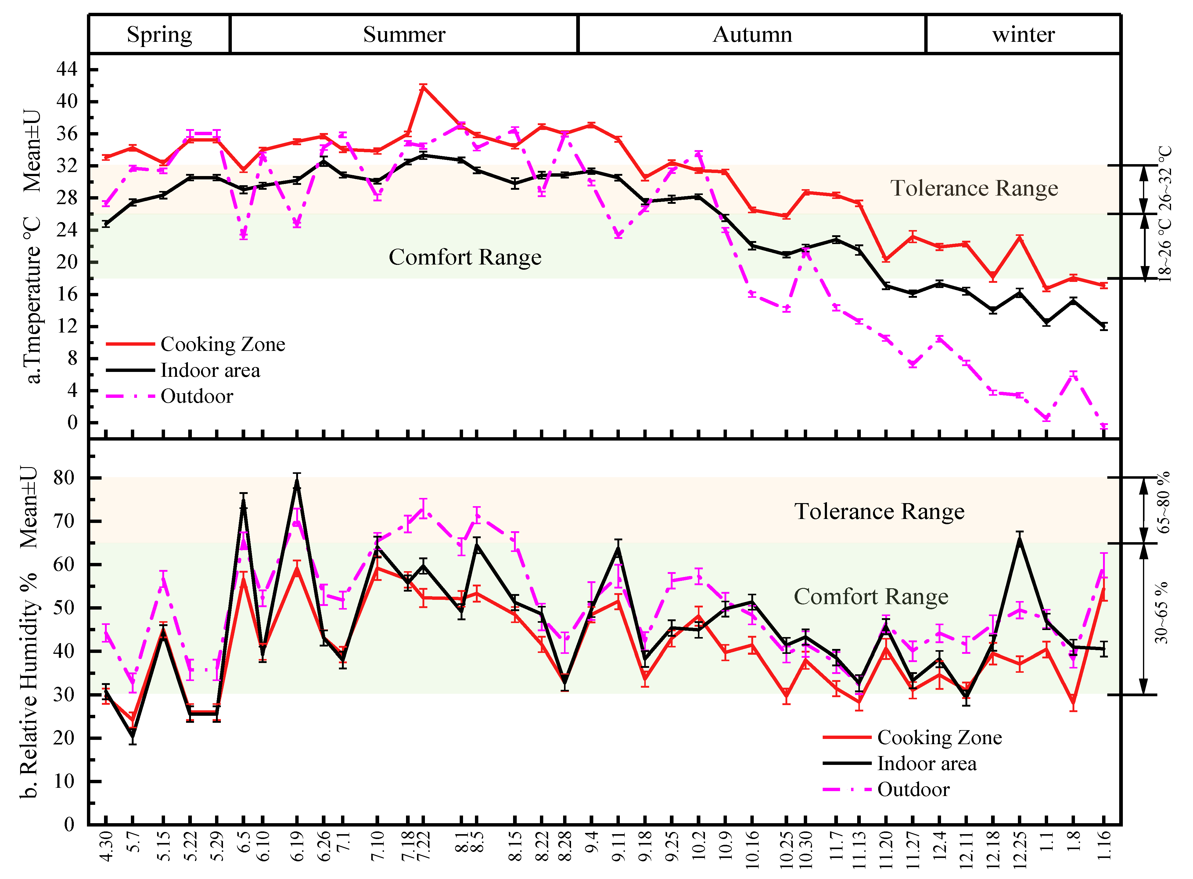
From Figure 3a, the temperature of the cooking zone was higher than that of the indoor area and outdoor. The annual variation range of the temperature in the cooking zone was 16.70 ± 0.30–41.81 ± 0.36 °C, and the highest temperature was 31.53 ± 0.31–41.81 ± 0.36 °C in summer, which was 2.50 ± 0.75–8.49 ± 0.83 °C higher than that in the indoor area. Contrary to temperature, the relative humidity in the cooking zone was lower than that in the indoor area and outdoors. It can be seen from the Figure 3b that the annual variation range of the relative humidity in the cooking zone was 24.20 ± 1.76–59.17 ± 2.71%RH, which was 4.00 ± 4.04–20.64 ± 3.99%RH lower than that in the indoor area. According to BSEN16282 [18], the comfortable range of the indoor temperature and the relative humidity in the breathing zone (breathing zone: at the height of 1.1 m above the floor at a distance of 0.5 m from the stoves) in commercial kitchens was 18–26 °C and 30–65%RH, respectively. The tolerance range was 26–32 °C and 65–80%RH, respectively. The data showed that the temperature in the cooking zone of the canteen kitchen was above the acceptable range (18–32 °C) in late spring, summer, and early autumn. It may be because the indoor environment of the canteen kitchen was highly dependent on the outdoor environment [34], and the waste heat cannot be effectively removed without the installation of an air-conditioning air supply system. It was necessary to explain that the breathing zone height specified in BEN16282 was 1.1 m. Considering the height difference of the chefs in different regions, the height of the breathing zone in this study was selected according to GB/T18883 [30], which recommended 0.5–1.5 m. In the indoor area, the height of the vegetable shelf was 1.0 m, and the height of the breathing zone when chefs took vegetables should be about 1.0 m. In the cooking zone, the breathing zone should be at 1.5 m when chefs are standing.
To analyze the annual variation of canteen kitchen temperature and relative humidity quantitatively. The seasonal variation of the temperature and relative humidity in different comfort ranges at different measurement points during working hours (6:40–13:40; 15:00–20:00) is shown in Figure 4.
Figure 4a shows that the comfort range of the temperature varies with seasons. The temperature distribution in spring and autumn were similar, with 64.88% and 76.92% of the working time in the cooking zone being in the acceptable range (18–32 °C), respectively. In the indoor area, 98.41% and 86.17% of the working time were in this range, respectively. The temperature in the cooking zone was the highest in summer. 82.92% of the working hours were above the acceptable range. In winter, 57.73% and 97.57% of the working time in the cooking zone and indoor area, respectively, were below the comfort range (18–26 °C). From Figure 4b, the relative humidity was in the comfortable range (30–65%RH) during most of the working time in the four seasons. For the indoor area in summer, 50.48% of the working time was within the tolerance range (30–80%RH). It may be due to the lower temperature in the indoor area. In order to fully understand the thermal comfort of the canteen kitchen, we analyzed the variation of temperature, relative humidity, and air velocity with time for a typical summer day in the next section.

3.2.2. Temperature, Relative Humidity and Air Velocity on Typical Test Day

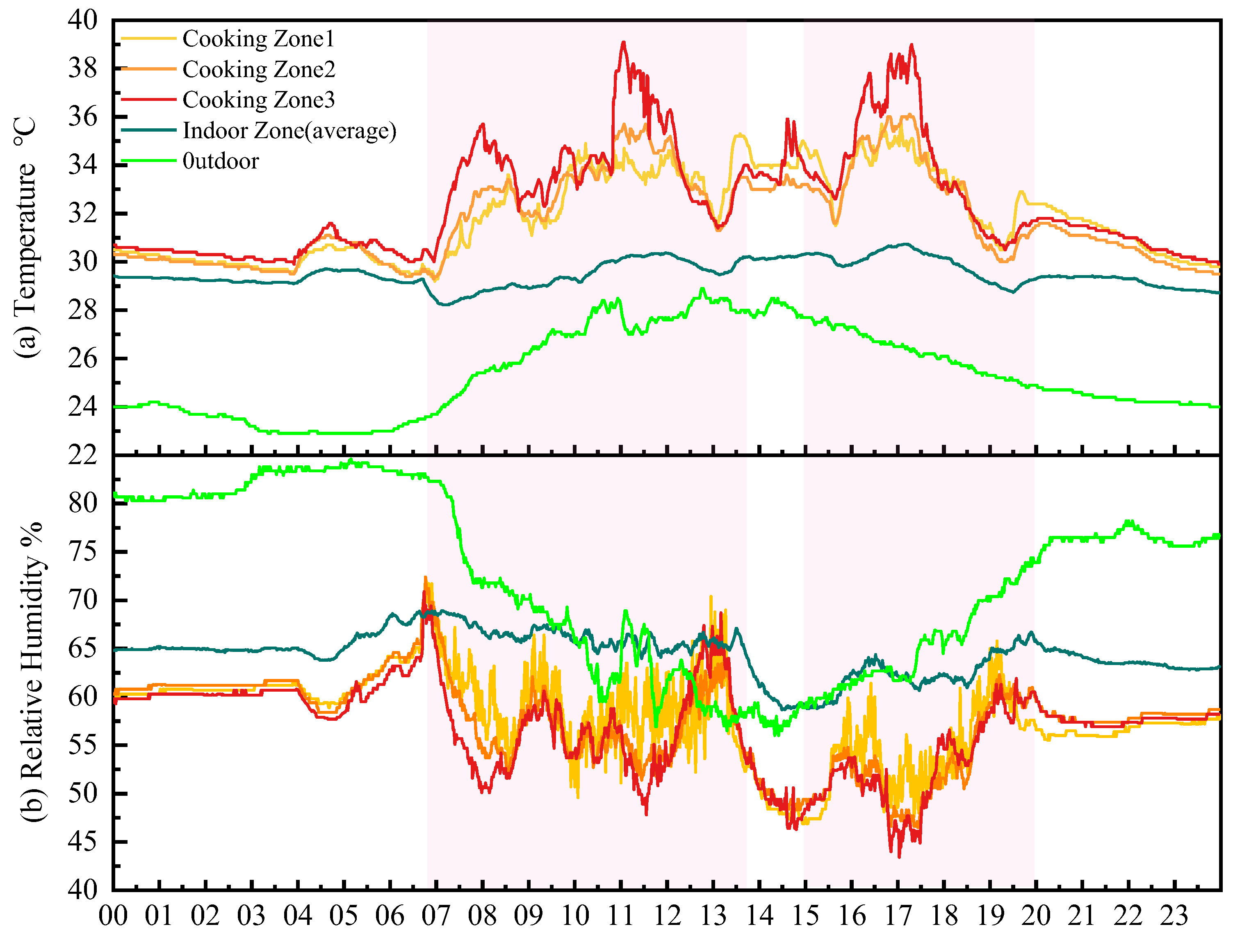
The statistical analysis showed that the thermal condition of the canteen kitchen was very bad. From Figure 5, we found that the temperature in the cooking zone of the canteen kitchen was between 29.20 ± 0.29–39.10 ± 0.29 °C and reached the temperatures peak at 8:00, 11:03 and 17:18. The maximum temperatures of measuring points were 71, 72, and 73 in the cooking zone were 35.90 °C, 36.1 °C, and 39.10 °C, respectively. It was different from the result reported by Li [16] that restaurants reached the highest peak at 12:50 at noon and 19:00, which may be due to the different work nature of restaurants and canteen kitchens. Canteen kitchens in colleges needed to provide three meals at a fixed period, while restaurants generally provided two meals and needed to start cooking according to the customers’ orders. Like the restaurants, the variation of relative humidity was contrary to the trend of temperature. The minimum relative humidities of measuring points 71, 72, and 73 in the cooking zone were 46.90% RH, 46.50% RH, and 43.40% RH, respectively, which were 12.00% RH, 18.50% RH and 18.30% RH lower than the indoor area relative humidity.
Figure 6 shows the air velocity at different measuring points for a typical day. According to BSEN16282 [18], the permissible mean air velocity should not be higher than 0.48 m/s when the indoor air temperature of a commercial kitchen is lower than 32 °C. We can see from Figure 6 that the air velocity of the measuring points in the indoor area met the standards’ value, while the air velocity of the measuring points 71,72 and73 in the cooking area were 0.53 ± 0.13 m/s, 0.52 ± 0.15 m/s, and 0.48 ± 0.13 m/s, respectively. Chefs may expose to higher air velocity during cooking, which was consistent with the questionnaire results that 91.60% of the chefs felt different degrees of draft sensation.

3.2.3. Effect of Stoves Status on Temperature and Relative Humidity

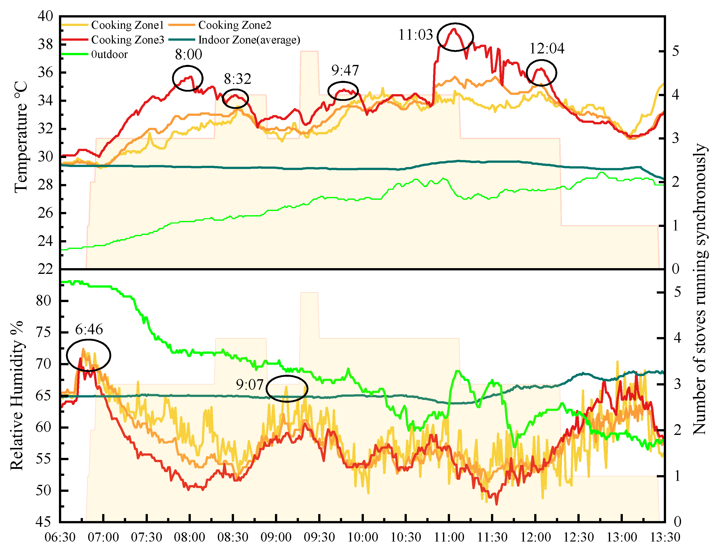
Figure 7 shows the variety of temperature and relative humidity at different measuring points in the canteen kitchen with the stoves’ status. Before the stoves opened, the temperature in the cooking zone decreased, and the relative humidity reached its peak. It was because the exhaust fan opened at 6:46, and the cooking zone was in a negative pressure status. The indoor air flowed into the cooking zone leading to the temperature decreasing and the relative humidity increasing. After the stoves opened, three stoves were used simultaneously between 6:50 and 8:17. The temperature at location 73 reached the highest of 35.70 °C. Three stoves were also used at the same time during 8:54–9:15. The highest temperature of location 73 during this time was 33.40 °C. However, the relative humidity at location 71 reached the maximum value of 66.40% RH at 9:07. It was due to the cooking methods having a significant effect on cooking zone temperature and relative humidity [35]. We listed the dishes corresponding to the temperature and relative humidity peaks in Table 4.
From Table 4, we can see that when three stoves were used simultaneously at 8:00, 9:07, and 12:04. At 12:04, the cooking methods of the three stoves were stir-frying or frying. At this time, the temperature of the cooking zone was 0.60 °C or 3.50 °C higher than that two or zero stoves were used to stir-fry or fry, respectively. Similarly, four stoves were used simultaneously at 8:32, 9:47, and 11:03. At 11:03, the cooking methods of the four stoves were stir-frying or frying. At this time, the temperature of the cooking zone was 4.30 °C or 4.70 °C higher than that of three or two stoves used to stir-fry or fry, respectively. It may be because when cooked dishes such as stir-fried noodles, stir-fried potato chips, or fried fish, a large amount of heat is released, and the temperature increases. Therefore, chefs can alleviate the overheating of the cooking zone during the cooking process by avoiding cooking stir-fried or fried dishes simultaneously.

3.2.4. Evaluation of Indoor Thermal Comfort in Canteen Kitchen

Thermal comfort is a comprehensive perception of temperature, relative humidity and air velocity. In this section, we used the two evaluation index: Predicted mean vote (PMV) and predicted percentage of dissatisfaction (PPD), proposed by Professor Fanger, to predict the thermal comfort of the canteen kitchen. Since the calculation formula for PMV value is complicated, and many parameters cannot be obtained directly, this paper calculates it according to Formula (4) [36].
P M V = a t + b p v + c
where, a , b , c is the coefficient, a = 0.212 , b = 0.293 , c = 5.949 . t is the air temperature, °C. is the partial vapor pressure, kPa . p v is calculated according to Formulas (5) and (6) [36]:
P w s = 611.2 exp ( 17.62 t 243.12 + t )
P v = φ P w s 1000
PPD is calculated by the Formula (7) [36]:
P P D = 100 95 [ ( 0.03353 P M V 4 + 0.2179 P M V 2 ) ]
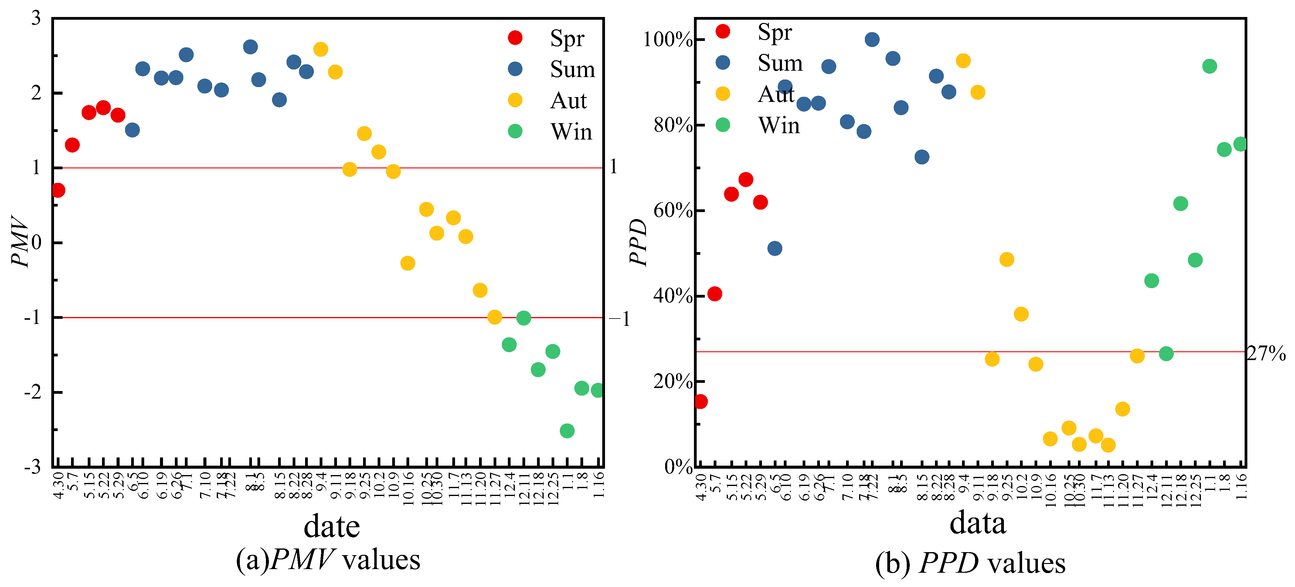
The calculated results are shown in Figure 8. The standard GB 50019 [37] stipulates that the value of PMV should be: −1 ≤ PMV ≤ 1; the PPD value should be: PPD ≤ 27%. From Figure 8a, we can find that the values of PMV distribution in spring and autumn were similar, and the chefs felt general or hot. Chefs will feel hot in summer. In winter, chefs felt neutral or cool. From Figure 8b, we can see that the PPD value was the highest in autumn and the lowest in summer. Taking 27% as the limit, there were 71.05% of the time in the whole year cannot achieve satisfactory results.

3.3. Results and Analysis of the Questionnaire

From Section 3.2.4, we used the evaluation index PMV-PPD to predict the indoor thermal comfort of the canteen kitchen. In order to investigate the chefs’ real feelings about the indoor environmental quality of the canteen kitchen, we conducted a questionnaire survey on the chefs in the test kitchen.

3.3.1. Chefs’ Satisfaction with Thermal Comfort in the Canteen Kitchen

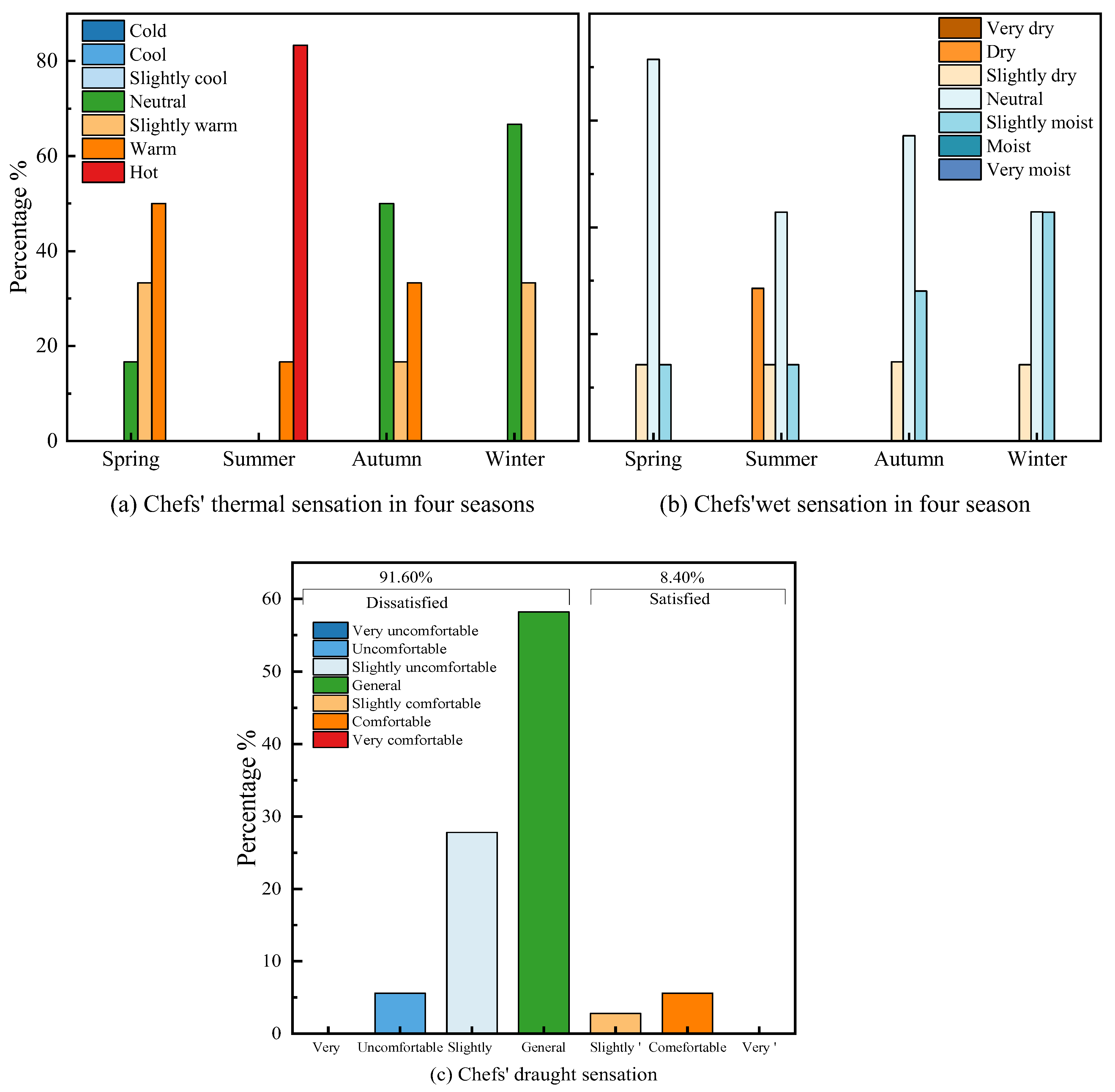
The chefs’ thermal, wet sensations in four seasons and the year-round draught sensation are shown in Figure 9. Figure 9a shows that the chefs’ thermal sensation varies with seasons. The sensation distribution in spring and autumn are similar, with 50.00% and 66.67% of chefs feeling neutral or slightly warm. In summer, 83.33% of chefs felt hot. Different from the test results, although 57.75% of the working time in the cooking zone and 97.58% of the working time in the indoor area were lower than the comfort limit of 18 °C, 33.33% of the chefs still felt slightly warm. It may be because the stoves are still not completely closed when not cooking dishes. From Figure 9b, most chefs’ wet sensations in the four seasons are neutral. However, 42.86% of chefs felt slightly dry or dry in summer, which may be due to the rapid evaporation of sweat in the high-temperature environment in the cooking zone. From Figure 9c, we can find that 91.60% of chefs were dissatisfied with the draught sensation.

3.3.2. Chefs’ Sensation of Indoor Air Quality in the Commercial Kitchen

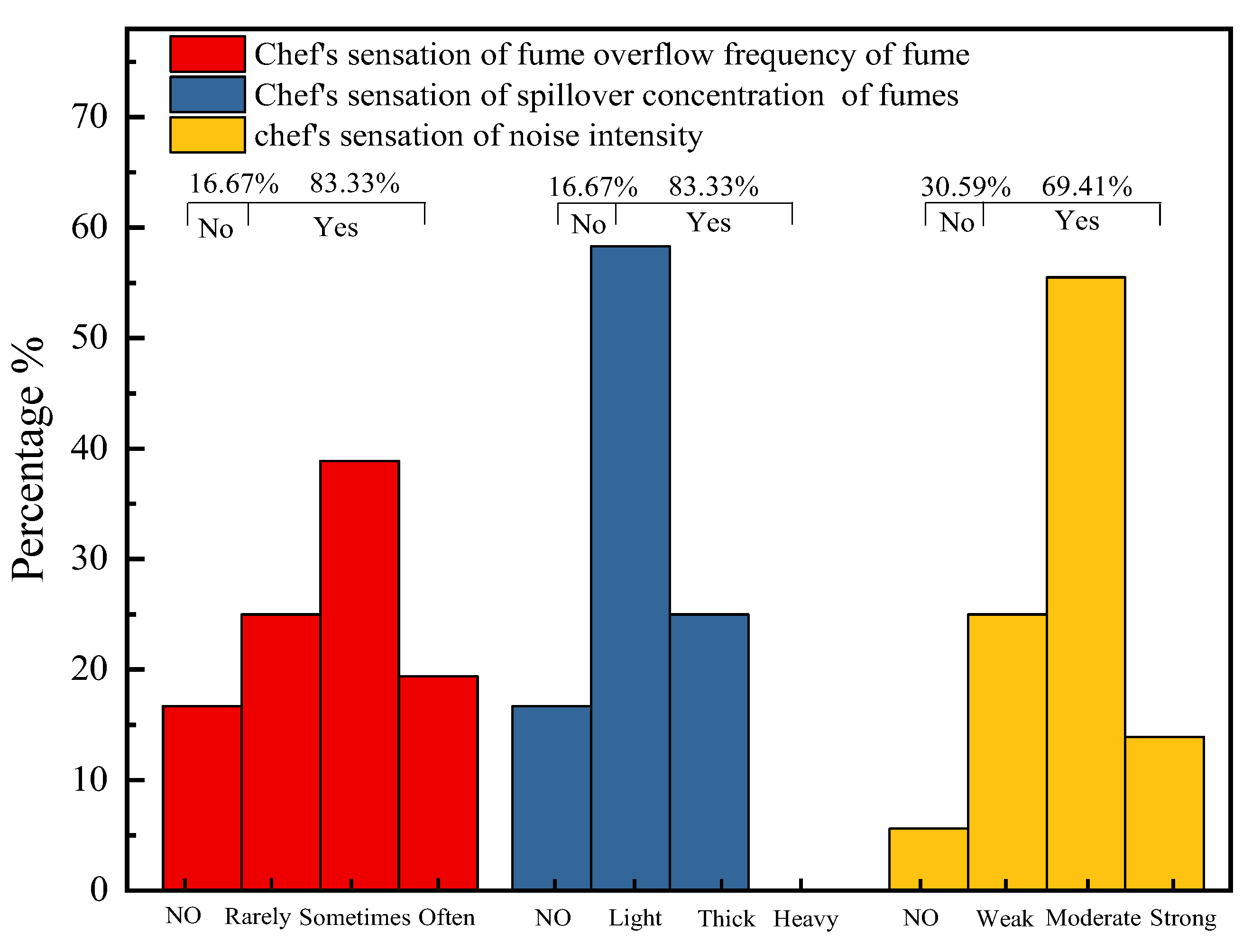
Chefs’ sensation of indoor air quality in kitchens is related to the exhaust fume system, as the system can capture and exhaust the cooking fumes to prevent them from overflowing into the cooking area. The chefs’ sensation of the fume overflow frequency, spillover concentration, and noise intensity are shown in Figure 10. From Figure 10, we can see that there are 83.33% of the chefs felt the fume overflow from the exhaust hood during the cooking process, 83.33% of the chefs could sense the fume in the cooking area, and 69.41% of the chefs felt the noise generated by the exhaust fume system. It indicated the spillover of fumes from the exhaust hood in the surveyed kitchen was serious. In addition, the acoustic environment of this kitchen was poor, which may reduce the work efficiency of chefs and endanger their health.

3.4. Exhaust Fume System

The kitchen exhaust fume system plays an important role in ensuring a comfortable indoor environment and removing pollutants. From Section 3.2 and Section 3.3, we found that the test kitchen is too hot in summer, the oil fume overflowed from the exhaust hood during cooking, and chefs were exposed to high air velocity, which may be due to poor local ventilation in this kitchen. In this section, we reported our attempts to assess the impact of the exhaust fume system on indoor environmental quality by measuring temperature, air velocity, oil fume concentration, and energy consumption.

3.4.1. Temperature

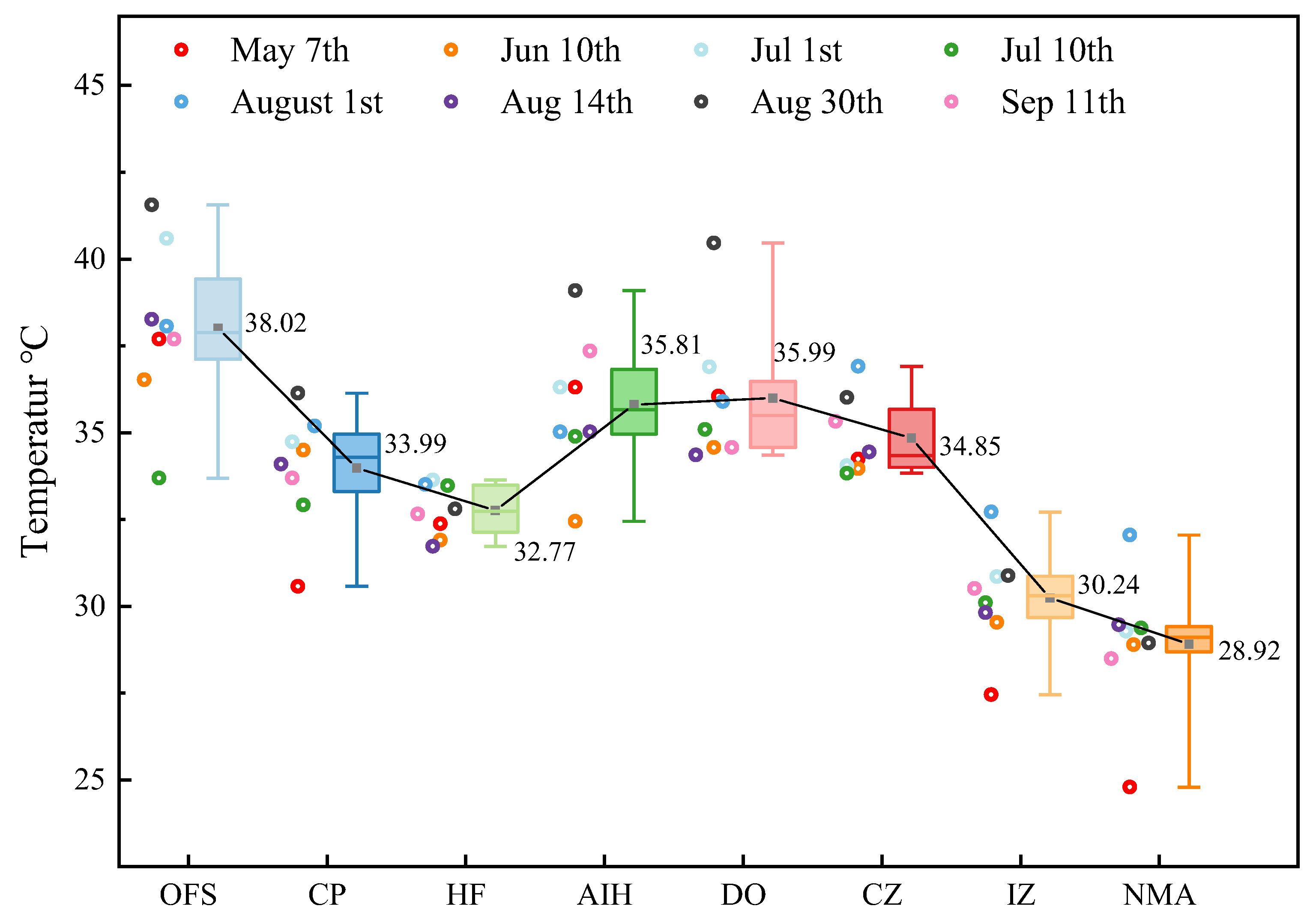
The temperature at different measurement points is shown in Figure 11. From Figure 11, we can see that the temperature of the exhaust fume system from high to low is as follows: oil fume source, discharge outlet, air inlet in the hood, cooking zone, capture point, hood face, indoor zone and natural makeup air outlet.
The heat source of each measuring point mainly came from the high-temperature flue gas released by cooking and fuel combustion. The measuring point of the oil fume source was closest to the heat source, so the temperature was the highest. The temperatures at the discharge outlet and air inlet in the hood were similar, and they were both higher than the hood face. It may be because the hood face was in a negative pressure state when the hood opened. The indoor low-temperature air mixed with the cooking fumes and flowed into the hood face. In addition, the high-temperature flue gas released by fuel combustion directly flowed into the air inlet in the hood and mixed with the cooking fumes and then discharged from the discharge outlet. Therefore, the temperature of the measuring points at the hood face was lower than the air inlet in the hood and discharge outlet. The capture points were close to the heat source, so their temperature was higher than the hood face.

3.4.2. Air Velocity and Airflow Rate

The air velocity at each measurement point of the exhaust fume system should be within a reasonable range. Too low cannot ensure the effective capture and discharge of oil fume pollutants; too high will cause noise, and long-term exposure to a noisy environment will reduce the chef’s work efficiency and harm their health [38,39]. The air velocity of each measurement point and recommended standard value are shown in Table 5.
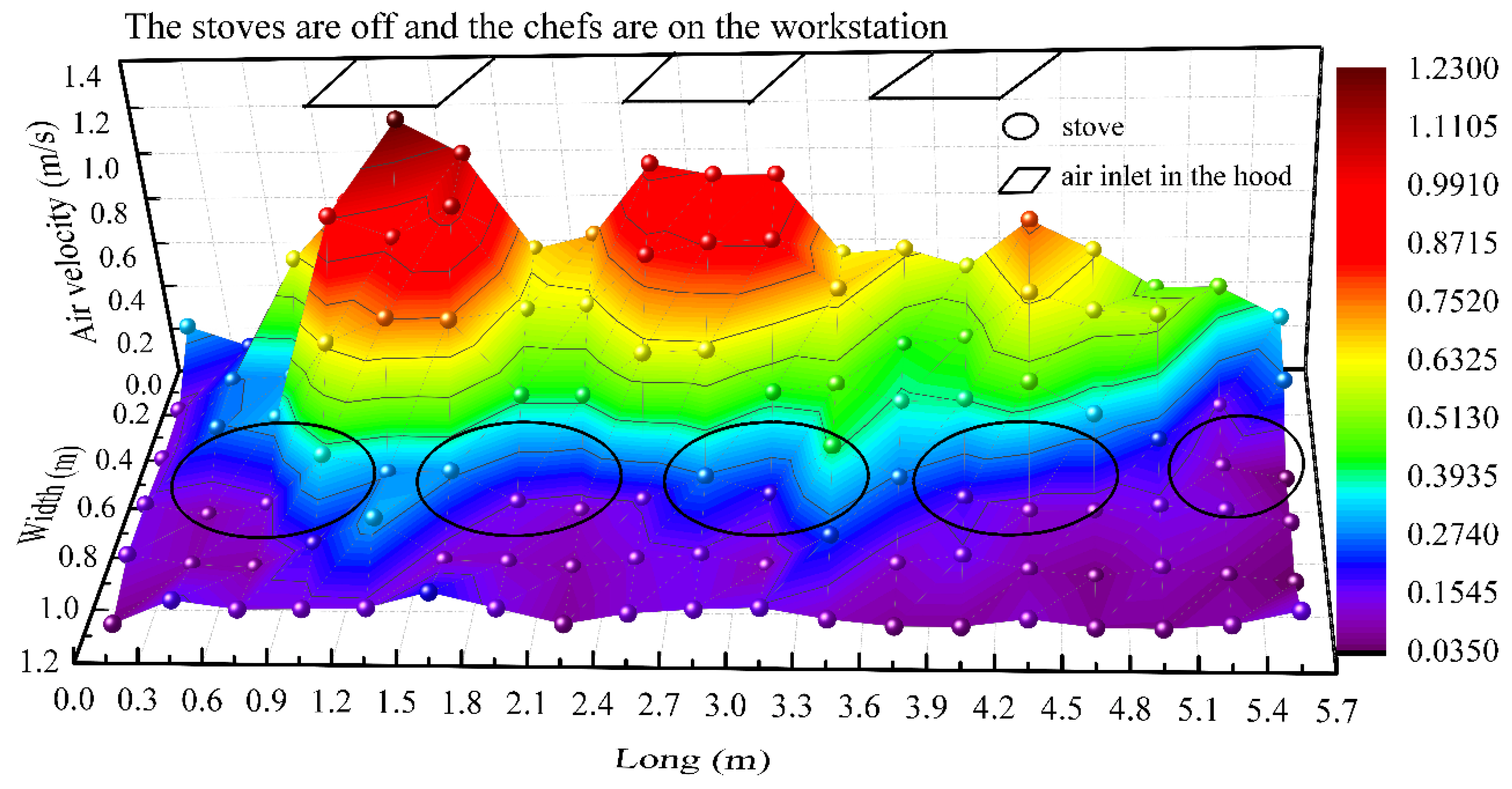
From Table 5, we can find the air velocities of capture points 11–14 were between 0.42 ± 0.06–0.66 ± 0.07 m/s, which met the requirement of the manual [40]. The air velocity of point 15 was significantly lower than the other four points. From Figure 1, there was no air inlet above point 15, and point 15 was far from air inlet 43. The air velocity of the hood face was between 0.35 ± 0.06–0.44 ± 0.06 m/s, which was lower than 0.5 m/s. It may be due to the uneven distribution of air velocity at the hood face. From Figure 12, we can see that the air velocity of the hood face close to the air inlet in the hood was higher than 0.5 m/s, and the maximum air velocity can reach 1.28 ± 0.06 m/s. The air velocity of points 41, 42, and 43 was 11.41 ± 0.25–12.86 ± 0.17 m/s, 8.21 ± 0.15–9.10 ± 0.18 m/s, and 6.35 ± 0.13–7.34 ± 0.10 m/s, respectively, which were much higher than the standards’ value. At the natural makeup air outlet, the air velocity was between 0.19 ± 0.06–0.78 ± 0.06 m/s, which met the standards’ value [20]. The data showed that the air velocity of each measurement point meets or even exceeds the standard values, which may lead to the chefs expose to high air velocity. Paradoxically, as high as 83.33% of the chefs felt that oil fumes are overflowing from the exhaust hood during cooking. That means that the exhaust airflow rate of this test kitchen is insufficient. Therefore, we calculate the exhaust airflow rate and the makeup airflow rate of this kitchen.
This test kitchen adopted the natural makeup air of the adjacent room to meet the makeup air requirements and used the exhaust fume system for local exhaust. The determination methods of exhaust airflow rate (LE) and makeup airflow rate (LM) were also given in JSCS2009 [20].
LE = Max (L1, L2)
L1 = 1000 × P × H
where: L1 is the exhaust airflow rate, m3/h; 1000 is the empirical coefficient, m/h; P is the perimeter of the exhaust hood (excluding the side against the wall), m; H is the distance between the hood face and the stoves surface, m.
L2 = 3600 × 0.5 × A
where: L2 is the exhaust airflow rate, m3/h; A is the area of hood face, m2
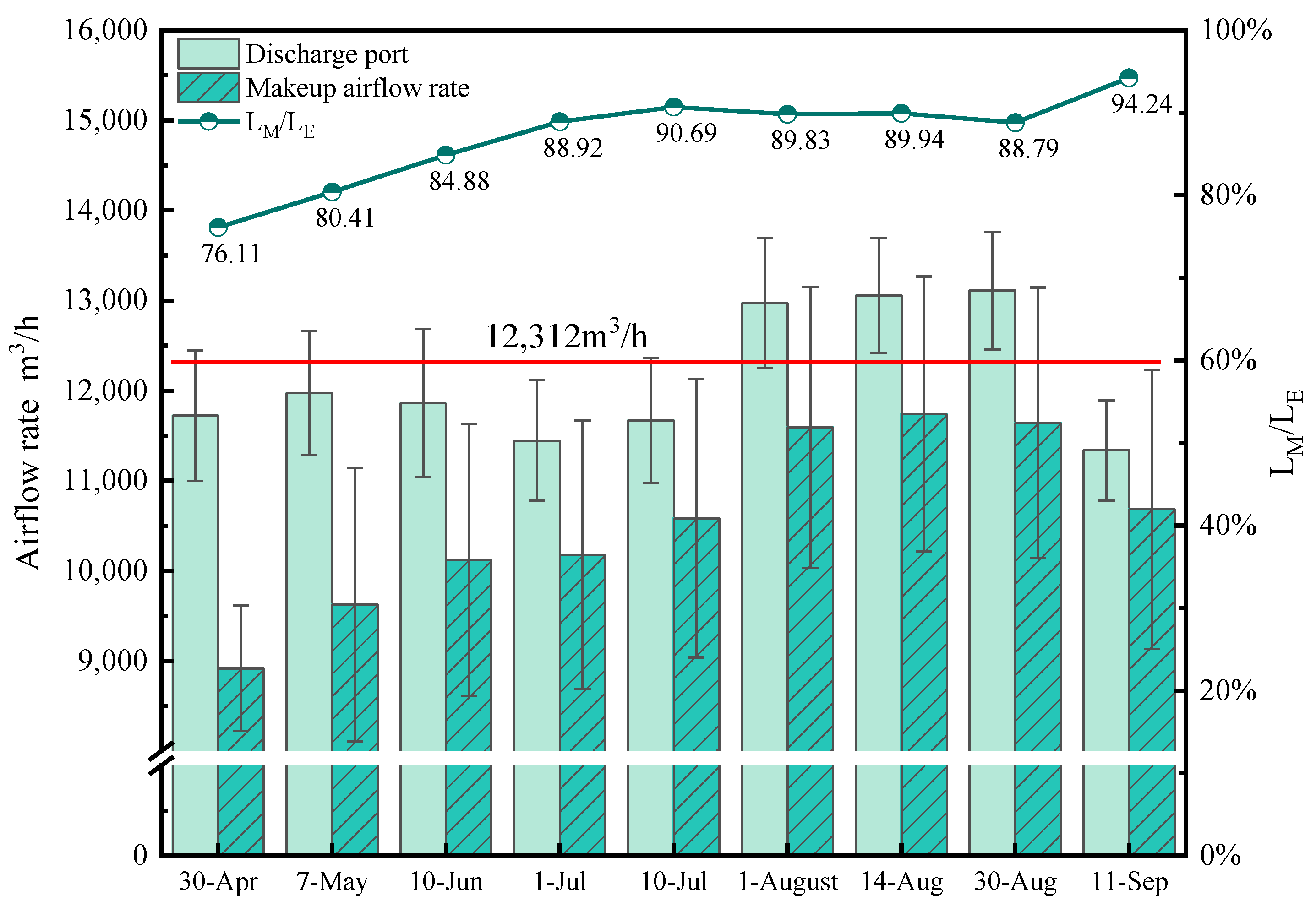
According to Formulas (8)–(10), the minimum exhaust airflow rate of this kitchen was 12312 m3/h. The makeup airflow rate should be 80%–90% of the exhaust airflow rate [2]. From Figure 13, we can find that the ratio of makeup airflow rate to exhaust airflow rate is between 76.11–94.24%, which is consistent with the standard value. However, the exhaust airflow rate of this kitchen is lower than the minimum value, which may lead to fumes overflowing from the exhaust hood during cooking.

3.4.3. Oil Fume Emission Concentration

(1)
Indoor oil fume generation—observed value
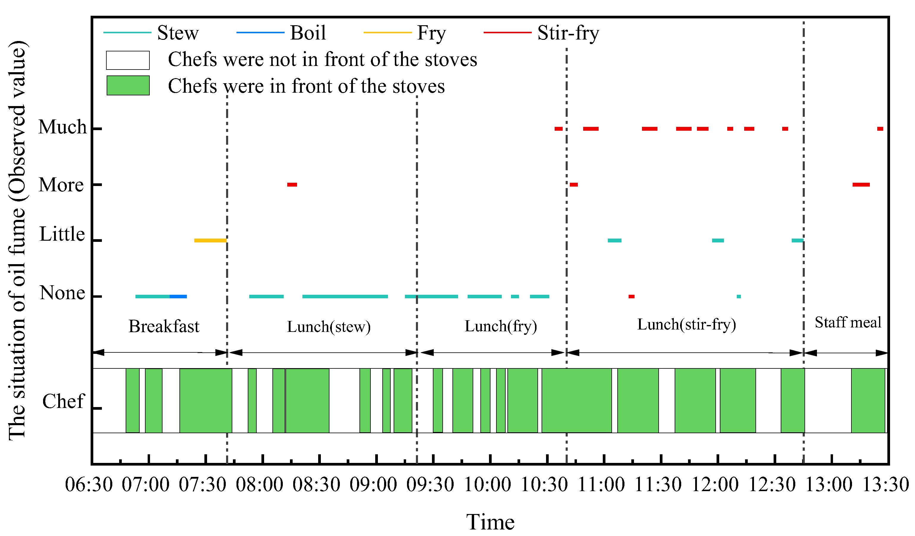
Field observation found that the amount of oil fume produced was different when cooking different dishes. In order to quantitatively analyze the influence of cooking methods on the amount of oil fume produced, the amount of oil fume produced during cooking of stove No.1 was divided into four categories: no oil fumes (none), a small number of oil fumes (little), more oil fumes (more), and a large number of oil fumes (much), as shown in Figure 14.
We can see from Figure 14 that during breakfast and lunch stew, the amount of oil fume was less, and a large amount of oil fume was produced during lunch stir-frying. In addition, boiling and stewing were the main cooking methods in the non-oil smoke production stage. When frying food produced little or more oil fume, when frying food produced more or much oil fumes. In summary, the production of oil fume was closely related to cooking methods, and the order from high to low was stir-frying, frying, stewing, and boiling.
(2)
Oil fume emission concentration at discharge outlet-test value
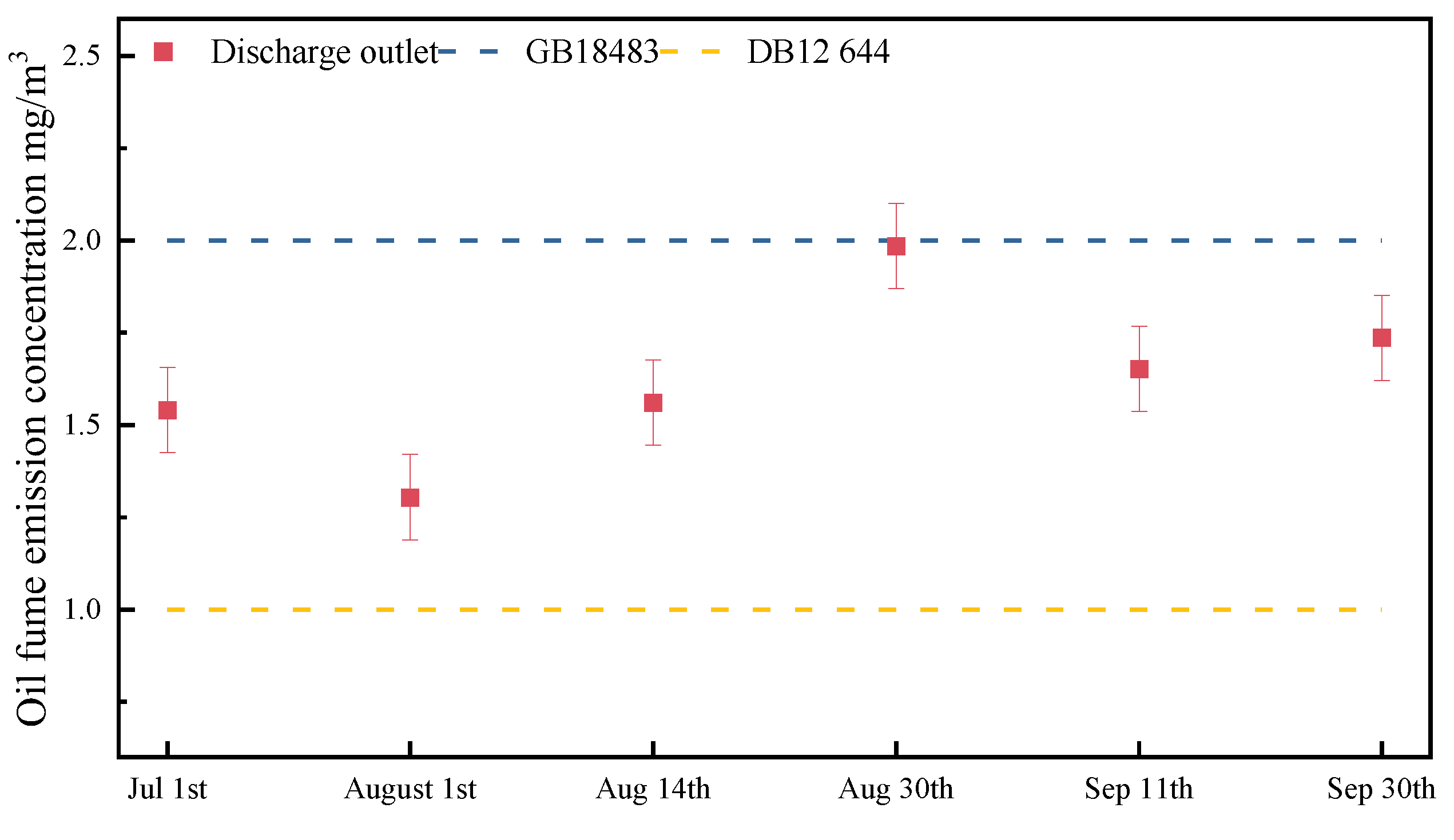
Figure 15 shows the oil fume emission concentration at the discharge outlet. It can be seen from Figure 15 that the oil fume emission concentration at the discharge outlet met the national standard GB18483-2001 [32]. However, the results did not meet the Tianjin standard DB12/644-2016 [41], that was because the purification equipment used in this exhaust fume system was produced and installed in April 2015, while the Tianjin standard was issued in 2016.

3.4.4. Energy Consumption Analysis of Exhaust Fume System

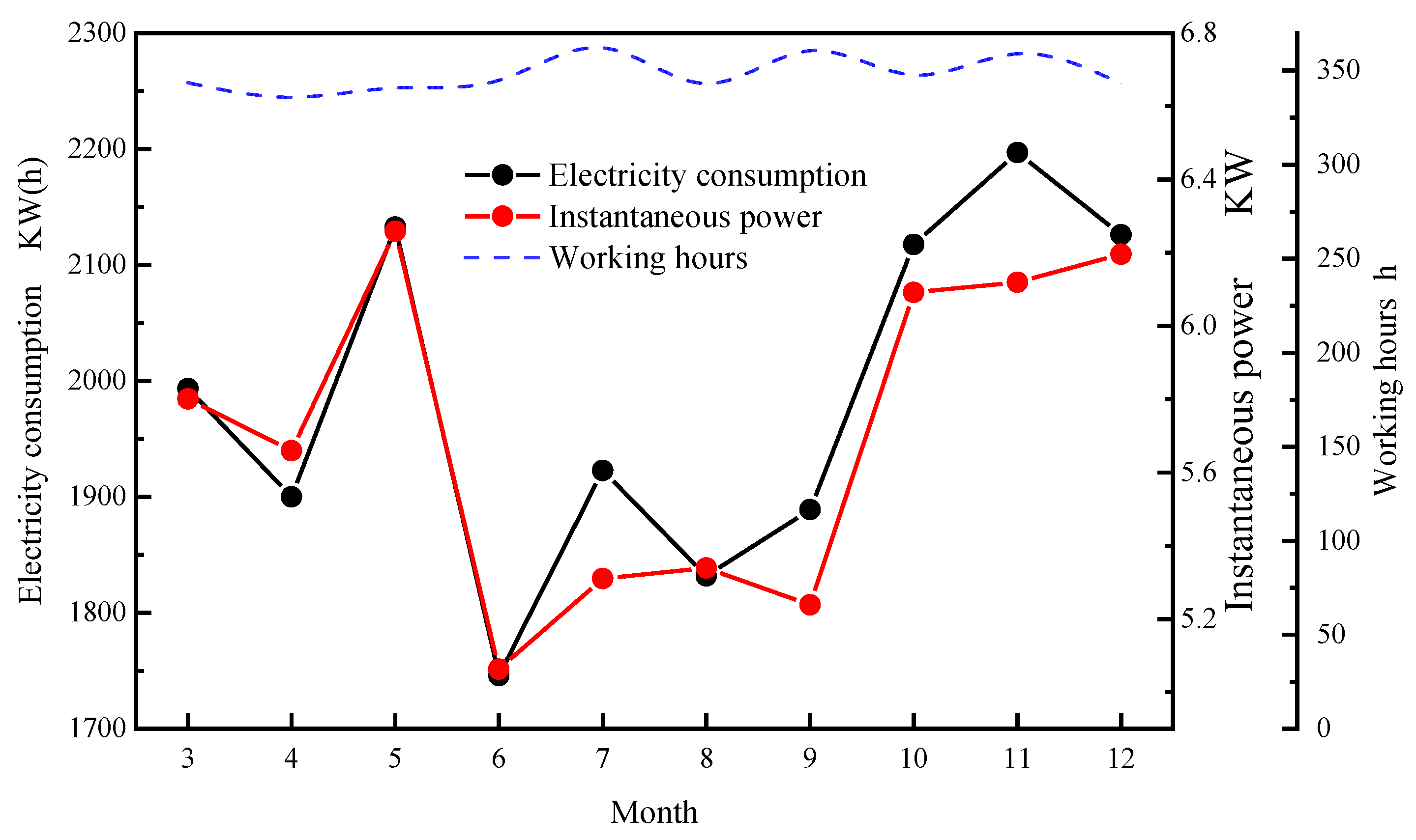
The monthly total electricity consumption, the monthly total working hours, and the monthly average instantaneous power of the exhaust fume system are shown in Figure 16. The oil fume purification integrated machine and the fixed-frequency blower were the primary electrical equipment of the exhaust fume system. Therefore, the energy consumption of this system depended on the instantaneous power and the working hours. From Figure 16, the working hours of the canteen kitchen were about 350 h per month, so the key factor affecting the energy consumption of the exhaust fume system was the instantaneous power. The electricity consumption increased in May, October, November and December. For May, the temperature began to rise in Tianjin. Chefs would open the air supply fan on warmer days, causing increased electricity consumption. After the maintenance of purification equipment on 14 September, the instantaneous power of purification equipment increased by 18.20% from the previous month, resulting in an increase in electricity consumption from October to December. Fisher, D [42] pointed out that the power range of the exhaust fan and makeup air fan in the commercial kitchen was 1.53 W/(m3/h) to 7.63 W/(m3/h). The power of the canteen kitchen was 0.47 W/(m3/h), which was lower than the commercial kitchens.

3.5. Discussion

In general, the indoor thermal environment of the commercial kitchen is complex, with high temperatures and high humidity. A proper ventilation system in a typical commercial kitchen is necessary to remove waste heat and oil fume pollutants. For commercial kitchens without air conditioning systems, especially in the cooking zone, about 82.92% of the working hours exceed the acceptable range in summer. Therefore, air conditioning systems are always needed to improve the indoor environment of commercial kitchens [21]. A personalized air conditioning system is worth recommending. It can not only ensure the chef’s thermal comfort but also has a certain energy -saving potential [43].
The kitchen exhaust fume system plays an important role in ensuring a comfortable indoor environment and removing pollutants. However, the test results show that only considering the exhaust hood information to design the exhaust fume system is unreasonable, which may lead to fumes overflowing from the exhaust hood during cooking. Based on this, our research group reported in another paper [44] on how select a suitable method for designing an exhaust fume system. The results show that it is necessary to combine the characteristics of commercial kitchens and comprehensive consideration of various factors such as kitchen civil engineering information, stove information, and exhaust hood information to design an appropriate exhaust fume system.

4. Conclusions

This paper reported a ten-month test including the indoor environment, outdoor environment, exhaust fume system, and makeup air system of a university canteen in Tianjin from April 2019 to January 2020. In addition, we also interviewed the chef’s thermal comfort in the canteen kitchen. The main conclusions were as follows.
(1)
The temperature in the canteen kitchen varied with the seasons. With 64.88% and 76.92% of the working time in the cooking zone being in the acceptable range (18–32 °C) in spring and autumn, respectively. In winter, the temperature was the lowest. The temperature in the cooking zone was the highest in summer, with about 82.92% of the working hours above the acceptable range.
(2)
The indoor air environment quality was affected by the cooking methods. When four stoves were used simultaneously, the cooking methods of four stoves were stir-frying or frying, the temperature of the cooking zone was 4.30 °C or 4.70 °C higher than that of three or two stoves used to stir-fry or fry, respectively. Therefore, chefs can alleviate the overheating of the cooking zone during the cooking process by avoiding cooking stir-fried or fried dishes simultaneously. In addition, the difference from the previous study result, the changing trend of the temperature and the relative humidity were opposite. It may be due to the traditional cooking methods of the Chinese canteen kitchen.
(3)
The questionnaire results were consistent with the test results. The chefs’ thermal sensations varied with the season. In summer, 83.33% of chefs felt hot. Most chefs’ wet sensations in the four seasons were neutral. In addition, there were 83.33% of the chefs felt the fume overflow from the exhaust hood during the cooking process, 83.33% of the chefs could sense the fume in the cooking area, and 69.41% of the chefs felt the noise generated by the exhaust fume system.
(4)
The exhaust fume system of the canteen kitchen was operated under the air velocity of 9.18 ± 1.60 m/s, and its exhaust airflow rate was 10,634.80 ± 189.30 m3/h, which was lower than the minimum exhaust airflow rate of 12,312 m3/h. This was probably the reason why the chefs felt the fume overflow from the exhaust hood.
From the general view, the indoor environment of the canteen kitchen is too hot in summer, and the fume overflow from the exhaust hood and the chefs expose to higher air velocity during cooking. The measurement results indicate that the exhaust fume system could not remove the waste heat and fume pollutants effectively.

Author Contributions

Conceptualization, N.D. and Y.L.; Data curation, M.F. and R.H.; Investigation, M.F.; Methodology, M.F.; Supervision, N.D.; Writing—original draft, M.F.; Writing—review and editing, N.D., Y.L., M.F. and A.Z. All authors have read and agreed to the published version of the manuscript.

Funding

The research was supported by the National Key Research and Development Program of China (No. 2017YFC0211502).

Institutional Review Board Statement

Not applicable.

Informed Consent Statement

Not applicable.

Data Availability Statement

The data presented in this study are available in the article.

Conflicts of Interest

The authors declare no conflict of interest.

References

  1. China Chain Store & Franchise Association. 2021 China Chain Catering Industry Report [R/OL]. Available online: http://www.ccfa.org.cn (accessed on 7 May 2022).
  2. National Bureaue of Statistics. Annual Number of Employees in Catering Industry in 2020 [EB/OL]. Available online: https://data.stats.gov.cn/easyquery.htm?cn=C01 (accessed on 7 May 2022).
  3. Shen, C. Survey Study on Exhaust Fume Systems and Exhaust Air Rate of Commercial Kitchen. Master’s Thesis, Tianjin University, Tianjin, China, 2020. [Google Scholar]
  4. Alama, M.S.; Sharmab, M.; Salvea, U.R. Assessment of thermal comfort in a hot and humid indoor built environment of a kitchen at a university canteen. Work A J. Prev. Assess. Rehabil. 2022, 72, 189–199. [Google Scholar] [CrossRef] [PubMed]
  5. Rahmillah, F.I.; Tumanggor, A.H.; Sari, A.D. The analysis of thermal comfort in kitchen. IOP Conf. Ser. Mater. Sci. Eng. 2017, 215, 012033. [Google Scholar] [CrossRef] [Green Version]
  6. Simone, A.; Olesen, B.W.; John, L.S.; Watkins, A.W. Thermal comfort in commercial kitchens (RP-1469): Procedure and physical measurements (Part 1). HVACR Res. 2013, 19, 1001–1015. [Google Scholar] [CrossRef]
  7. Giwa, S.O.; Nwaokocha, C.N.; Sharifpur, M. An appraisal of air quality, thermal comfort, acoustic, and health risk of household kitchens in a developing country. Environ. Sci. Pollut. Res. 2022, 29, 26202–26213. [Google Scholar] [CrossRef]
  8. Wang, L.; Xiang, Z.; Stevanovic, S.; Ristovski, Z.; Salimi, F.; Gao, J.; Wang, H. Role of Chinese cooking emissions on ambient air quality and human health. Sci. Total Environ. 2017, 589, 173–181. [Google Scholar] [CrossRef]
  9. Liu, S.; Cao, Q.; Zhao, X.; Lu, Z.; Deng, Z.; Dong, J.; Lin, X.; Qing, K.; Zhang, W.; Chen, Q. Improving indoor air quality and thermal comfort in residential kitchens with a new ventilation system. Build. Environ. 2020, 180, 107016. [Google Scholar] [CrossRef]
  10. Liu, S.; Dong, J.; Cao, Q.; Zhou, X.; Li, J.; Lin, X.; Qing, K.; Zhang, W.; Chen, Q. Indoor thermal environment and air quality in Chinese-style residential kitchens. Indoor Air 2020, 30, 198–212. [Google Scholar] [CrossRef]
  11. Wang, X.; Liu, X.; Xi, G. Numerical Analysis on Thermal Environment Evalustion in Kitchen with Range Hood. J. Xi’an Jiao Tong Univ. 2013, 47, 120–125. [Google Scholar]
  12. Chen, R. Numerical Simulation of Pollution Control in Commercial Kitchen. Master’s Thesis, Tianjin University, Tianjin, China, 2019. [Google Scholar]
  13. Zhao, Y.; Li, A.; Tao, P.; Gao, R. The impact of various hood shapes, and side panel and exhaust duct arrangements, on the performance of typical Chinese style cooking hoods. Build. Simul. 2013, 6, 139–149. [Google Scholar] [CrossRef]
  14. Dobbina, N.A.; Sun, L.; Wallace, L.; Kulka, R.; You, H.; Shin, T.; Aubin, D.; St-Jean, M.; Singer, B.C. The benefit of kitchen exhaust fan use after cooking—An experimental assessment. Build. Environ. 2018, 135, 286–296. [Google Scholar] [CrossRef]
  15. Yi, K.W.; Kim, Y.I.; Bae, G.N. Effect of air flow rates on concurrent supply and exhaust kitchen ventilation system. Indoor Built Environ. 2016, 25, 180–190. [Google Scholar] [CrossRef]
  16. Li, A.; Zhao, Y.; Jiang, D.; Hou, X. Measurement of temperature, relative humidity, concentration distribution and flow field in four typical Chinese commercial kitchens. Build. Environ. 2012, 56, 139–150. [Google Scholar] [CrossRef]
  17. ANSI/ASHRAE Standard 154; Ventilation for Commercial Cooking Operations. American Society of Heating, Refrigeration, and Air-Conditioning Engineers: Atlanta, GA, USA, 2016.
  18. BS EN 16282; Equipment for Commercial Kitchens–Components for Ventilation in Commercial Kitchens. BSI Standards: London, UK, 2017.
  19. GB/T 17713-2011; State Bureau of Quality and Technical Supervision. Range Hood: Beijing, China, 2012.
  20. Ministry of Housing and Urban-Rural Development-Engineering Quality and Safety Supervision Division, China Institute of Building Standard Design and Research. National Technical Measures for Design of Civil Construction, Heating Ventilation and Air Conditioning; China Planning Press: Beijing, China, 2009; pp. 1–100. [Google Scholar]
  21. JGJ 64; Standard for Design of Dietetic Buildings. Minstry of Housing and Urban-Rural Development of the People’s Republic of China: Beijing, China, 2017.
  22. Hao, C.; Yang, Y. Analysis for poor ventil ation in a university refectory. HV AC 2008, 38, 105–107. [Google Scholar]
  23. Zhang, Q. Ventilation Design of Large Refectory. Manag. Innov. 2014, 1, 2. [Google Scholar]
  24. Cai, H. Design and Thinking of the Ventilation System for College Canteen Buildings. Build. Energy Environ. 2020, 39, 101–103. [Google Scholar]
  25. Song, S. Ventilation Design of Large Refectory. For. Sci. Technol. Inf. 2005, 37, 32–33. [Google Scholar]
  26. China National Food and Drug Administration. Notice on the Launch and Issuance of the Catering Service License. No.257[EB/OL]. 2009. Available online: https://wenku.baidu.com/view/a6c41597dd88d0d233d46a37.html (accessed on 2 December 2021).
  27. WS/T 757; The Applicable Guide of Standardized Specification of Work Safety for Metal and Nonmetal Opencast Mines. China Coal Industry Publishing House: Beijing, China, 2016.
  28. He, W.; Gang, T.; Nie, L.; Qu, S.; Li, J.; Wang, M. Preliminary study Concerning Emission of Volatile Organic Compounds from Cooking Oils. Environ. Sci. 2012, 33, 2973–2978. [Google Scholar]
  29. GB/T 18204.1-2013; Examination Methods for Public Places-Places-Part 1: Physical Parameters. General Administration of Quality Supervision, Inspection and Quarantine of the People’s Republic of China, China National Standardization Administration: Beijing, China, 2013.
  30. GB/T18883; Indoor Air Quality Standard. State Environmental Protection Administration, Ministry of Health, General Administration of Quality Supervision, Inspection and Quarantine of the People’s Republic of China, Standard Press of China: Beijing, China, 2002.
  31. GB/T 16157-1996; Determination of Particulates and Sampling Methods of Gaseous Pollutants Emitted from Exhaust Gas of Stationary Source. Ministry of Environmental Protection of the People’s Republic of China: Beijing, China, 1996.
  32. GB18483-2001; Emission Standard of Cooking Fume. Ministry of Ecology and Environment of the People’s Republic of China: Beijing, China, 2001.
  33. JJF1059.1-2012; Evaluation and Expression of Uncertainty in Measurement. General Administration of Quality Supervision, Inspection and Quarantine of the People’s Republic of China: Beijing, China, 2012.
  34. Dear, R.J.D.; Brager, G.S. Thermal comfort in naturally ventilated buildings: Revisions to ASHRAE Standard 55. Energy Build. 2002, 34, 549–561. [Google Scholar] [CrossRef] [Green Version]
  35. Lu, F.; Shen, B.; Yuan, P.; Li, S.; Sun, Y.; Mei, X. The emission of PM2.5 in respiratory zone from Chinese family cooking and its health effect. Sci. Total Environ. 2018, 10, 397. [Google Scholar] [CrossRef]
  36. Wang, G.; Jiang, Y.; Shi, H.; Wang, Y. Numerical Analysis of Indoor Thermal Comfort in Large Commercial Kitchen. World Sci.-Technol. R D 2014, 36, 236–240. [Google Scholar]
  37. GB 50019; Design Code for Heating Ventilation and Air Conditioning of Industrial Buildings. Ministry of Housing and Urban-Rural Development of the People’s Republic of China: Beijing, China, 2015.
  38. Yang, H. Study on Noise Control of Air Conditioning and Ventilation Ducts. Master’s Thesis, Jiangsu University of Science and Technology, Zhenjinag, China, 2021. [Google Scholar]
  39. Wu, J. Active Passive Compound Control of Ventilation Duct Noise. Master’s Thesis, University of Information Engineering, Nanjing, China, 2021. [Google Scholar]
  40. Lu, Y.Q. Heating Ventilation Design Manual; Architecture and Building Press: Beijing, China, 2007. [Google Scholar]
  41. DB12/ 644-2016; Emission Standard of Cooking Fume. Tianjin Environmental Protection Bureau: Tianjin, China, 2016.
  42. Fisher, D. Prediting energy consumption. Ashrae J. 2003, 45, k8–k13. [Google Scholar]
  43. Li, Z. Simulation Analysis and Experimental Study on Air-Flow Organization and Energy Consumption of Commercial Kitchen. Master’s Thesis, Nanjing University of Aeronautics and Astronautics, Nanjing, China, 2016. [Google Scholar]
  44. Du, T. Research on Key Factors Affecting Extract Air Flow Rate and Ventilation Simulation of Commercial Kitchen. Master’s Thesis, Tianjin University, Tianjin, China, 2021. [Google Scholar]
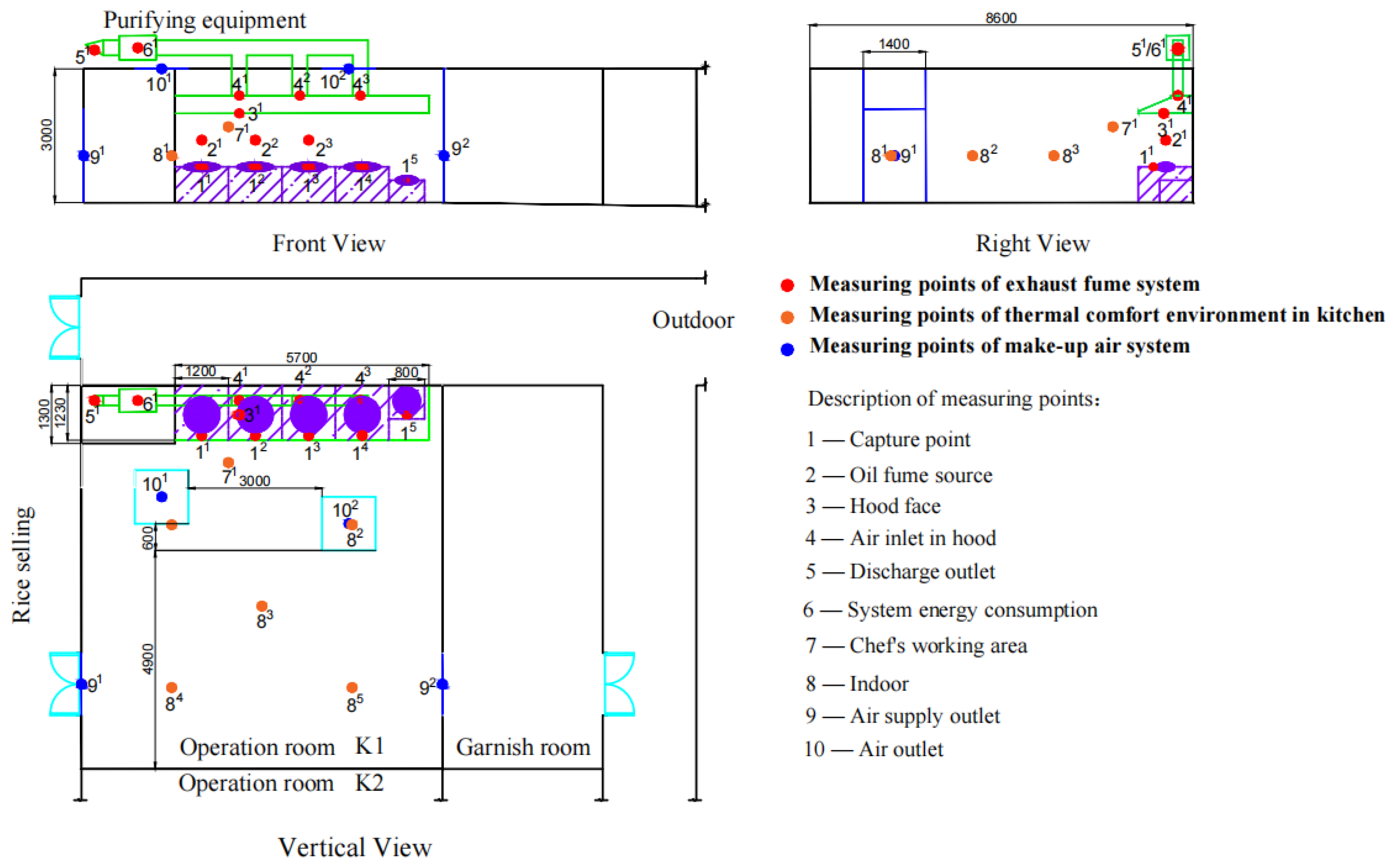
Figure 1. Location of measuring points in the canteen kitchen.
Applsci 12 11755 g001
Figure 2. The usage status of stoves and the situation of chefs standing in front of the stoves on a typical test day.
Applsci 12 11755 g002
Figure 3. The average values of temperature and humidity in the cooking peak time interval of cooking peak (10:55–10:04).
Applsci 12 11755 g003
Figure 4. The seasonal variation of the temperature and relative humidity in different comfort ranges of the indoor environment in the kitchen.
Applsci 12 11755 g004
Figure 5. The variation of temperature and relative humidity at different measurement points with time.
Applsci 12 11755 g005
Figure 6. Air velocity at different measurement points in the canteen kitchen.
Applsci 12 11755 g006
Figure 7. The variety of temperature and relative humidity at different measurement points with the stoves’ status.
Applsci 12 11755 g007
Figure 8. PMV values and PPD values.
Applsci 12 11755 g008
Figure 9. Chefs’ thermal, wet and draught sensation.
Applsci 12 11755 g009
Figure 10. Chefs’ sensation of indoor air quality in the canteen kitchen.
Applsci 12 11755 g010
Figure 11. Temperature of exhaust fume system and indoor measuring points.
Applsci 12 11755 g011
Figure 12. The cloud diagram of air velocity of the hood face.
Applsci 12 11755 g012
Figure 13. The exhaust airflow rate and the makeup airflow rate of the test kitchen.
Applsci 12 11755 g013
Figure 14. Oil fume generation of stove 1 during cooking (observed value).
Applsci 12 11755 g014
Figure 15. Oil fume emission concentration at discharge outlet.
Applsci 12 11755 g015
Figure 16. Relationship between monthly total electricity consumption and monthly average instantaneous power of oil fume exhaust system.
Applsci 12 11755 g016
Table 1. Test period and sampling time for each parameter.
Measuring PointParameterTest PeriodSampling Time
Exhaust fume systemVelocityTwice a month10 s
TemperatureTwice a month10 s
Oil fume concentrationTwice a month10 min
Energy consumptionContinuous1 s
Indoor environment and make-up air systemVelocityTwice a month10 s
Temperature1 day per week1 s
Humidity1 day per week1 s
Outdoor environmentalTemperature1 day per week1 s
Humidity1 day per week1 s
Table 2. Measuring instruments information.
NameModelParametersRangePrecision
Hot-wire AnemometerTesto 405iTemperature−20 ± 60 °C±0.5 °C
Velocity0–30 m/s±(0.1 m/s + 0.5% Measured value) (0–2 m/s)
±(0.3 m/s + 0.5% Measured value) (2–15 m/s)
Temperature and Humidity RecorderRC-4HA/CTemperature−30 ± 60 °C±0.5 °C
Humidity0–99% RH±0.3% RH
Microcomputer Oil Fume samplerTH-880F(O2)Oil fume emission concentrationSample flow rate: 5–60 L/minInaccuracy ≤ ±2.5%
Infrared SpectrophotometerJLBG-126UOil fume emission concentration2, 5, 20, 50, 100 mg/L 2, 5, 20 mg/L ≤ ± 10%
50 mg/L ≤ ±5% 100 mg/L ≤ ±2%
Electricity RecorderEX300Energy consumptionVoltage: 15–500 V
Current: 0.01–5 A
Current: ±0.2% FS
Voltage: ±0.2% FS
Electricity: ±0.5% FS
Table 3. Basic information about chefs.
Number of ChefsPercentage (%)
Gender
Male2775.00
Female925.00
Age
16–20925.00
21–301644.44
31–40513.89
≥41616.67
Hight (cm)
150–160719.44
161–1701438.89
171–1801438.89
≥18112.78
Note: The chefs participating in cooking activities are all male, and they are above 160 cm.
Table 4. Dishes at different times.
StoveDishes Name
8:009:0712:048:329:4711:03
34
No.1Stir-fry noodlesMapo tofuStir-fry potato chipsStir-fry cabbageStewed chick with mushroomStir-fry beans
No.2Stir-fry rice with eggBoil waterStir-fry cabbageBraised meatStir-fry pork with green pepperStir-fry chicken
No.3Thaw meatCooking soupStir-fry cabbageCooking soupCooking soupFry fish
No.4OffOffOffThaw meatFry fishStir-fry cabbage
No.5OffOffOffOffOffOff
Table 5. Air velocity at each measuring point of the oil fume exhaust system.
Measuring PointsCapture PointHood FaceAir Inlet in the HoodNatural Makeup Air Outlet
111213141534142439192
Standard Value0.25–0.5 m/s [40]≥0.5 m/s [20]4–5 m/s [20]≤1 m/s [20]
30-Apr0.550.660.680.470.170.3511.419.107.000.660.21
±U0.060.070.070.060.070.070.250.180.140.060.01
7-May0.500.570.630.550.210.4012.868.776.730.670.19
±U0.060.060.060.060.060.060.170.110.130.060.06
10-Jun0.530.460.450.520.360.4411.908.217.060.700.20
±U0.090.070.060.070.060.060.150.150.080.060.06
1-Jul0.430.450.430.460.290.4012.098.396.730.780.31
±U0.060.070.080.060.070.060.180.220.080.060.06
10-Jul0.520.460.550.520.120.3511.788.716.950.570.32
±U0.060.060.070.060.060.060.200.290.100.060.06
1-Aug0.540.400.580.500.110.3511.878.746.980.640.34
±U0.060.060.070.070.060.060.140.190.170.060.06
14-Aug0.520.510.500.520.220.3512.048.567.340.700.31
±U0.060.060.060.060.060.060.210.170.100.060.06
30-Aug0.480.530.510.460.190.3511.989.046.350.690.31
±U0.060.060.070.090.060.060.150.140.130.060.06
11-Sep0.530.460.420.420.220.3611.958.696.600.730.22
±U0.090.070.060.060.060.060.170.090.200.060.06
Publisher’s Note: MDPI stays neutral with regard to jurisdictional claims in published maps and institutional affiliations.