Abstract
This paper presents a novel design of discrete-time dual internal model-based repetitive control systems. The design strategy is accomplished by combining general and high-order modified repetitive control schemes for simultaneous tracking repetitive tasks and rejection of uncertain periodic disturbances. The proposed controller is constructed from two different discrete-time internal models, rendering a dual internal model-based repetitive controller (DIMRC). The first internal model is intended to track repetitive commands with a fixed fundamental frequency. Meanwhile, the second internal model is coupled to compensate for an exogenous periodic disturbance with an uncertain frequency. The controller structure, stability conditions, and convergence analysis are discussed in this paper. The performance of the proposed controller is validated through simulation studies showing accurate tracking and excellent disturbance rejection simultaneously.
1. Introduction
Repetitive control (RC) is a learning control scheme utilizing an internal model principle by Francis and Wohnam [] for accurate reference tracking or good disturbance rejection of the periodic signals. The inclusion of internal model inside the feedback loop establishes a generator of periodic control signal, enabling a null steady-state tracking error. The early applications of RC for reference tracking and disturbance rejection problems were listed by Hillerstrom and Walgama [], followed by Kurniawan et al. []. Recently, RC was developed and applied in many different applications such as wind-turbines [], inverter compressor refrigeration fields [], magnetically suspended rotor systems [], functional electrical stimulation [], nano-positioning systems [], centrifugal compressors [], and many others.
In principle, RC design comprises two parts, i.e., a stabilizing controller and an internal model. In the RC-controlled system, the stabilizing controller, sometimes called the compensator/learning function, is required to stabilize the closed-loop model. In addition, the stabilizing controller also determines the convergence speed of the system error. On the other hand, the internal model represents the reference/disturbance model, which later behaves as a periodic signal generator. This internal model makes accurate reference tracking/good disturbance rejection possible.
Some important works related to the internal model design can be found in [,,,,,]. The first digital internal model obtained by discretizing the continuous-time delay was given in []. The internal model [] has a finite-dimensional structure and provides a null steady-state tracking error for any periodic signal at a fundamental frequency and its harmonics up to Nyquist frequency components. The internal model [] was successfully applied to the control of a single-axis electric servomechanism using a 16-bit microprocessor. In [], a low-pass filter is added to discrete-time internal model [] intended to improve the system robustness against high-frequency models. Hillerstrom and Sternby [] presented a low-order internal model targeting specific band-limited periodic references/disturbances. The discrete-time internal model specifically used to track/compensate odd-harmonic periodic references/disturbances was proposed in []. In [], the discrete-time design of the internal model was developed to track or suppress periodic signals consisting of two or more fundamental frequencies. A discrete-time higher-order internal model for tracking/rejecting periodic signals with uncertain periods was introduced in []. In addition to some works on the internal models, several recent works on the development and application of RCs can be found in [,,,]. A robust RC with an optimized-band-stop filter for achieving high accuracy in nanopositioning stages was proposed in []. In [], the discrete-time RC with an active disturbance rejection control was implemented to realize high-precision permanent magnet synchronous motor drives. A design of higher-order RC with a phase lead stabilizing controller applied for a two-level grid-connected inverter was presented in []. Lu et al. [] developed the high-order selective harmonic RC scheme to improve the steady-state tracking accuracy of the pulse-width modulation converters. The works in [,,,,,,,,,] aimed to develop and utilize the internal model-based RC for either periodic reference tracking or disturbance rejection. This also implies that the proposed RC designs are not intended to simultaneously track and reject periodic signals.
In this work, we focus on the internal model design used for simultaneous reference tracking and disturbance rejection. More specifically, we develop a control strategy for tracking repetitive reference and rejection of uncertain periodic disturbance of a discrete-time linear system. This is motivated by the fact that tracking and rejection are common problems in control systems. Tracking repetitive trajectories can be found in many applications, such as robotics, power sources, precision gantry systems, engine valve systems, etc. []. Here, we also consider a disturbance rejection problem, where the disturbance period is uncertain or varying. Such disturbance appeared in many practical situations, such as rotating machines [,], active suspension systems [,], steel casting processes [,], and many others. When the actual disturbance period is subject to variation, the general internal model will operate with a period mismatch. This condition makes the RC gains at the disturbance’s frequencies drastically drop to low-level magnitudes. Consequently, the perfect disturbance attenuation is no longer applicable and the tracking accuracy is degraded. Therefore, the higher-order internal model is adopted to improve the attenuation performance when the disturbance period is varied. In this paper, a systematic approach to integrating two different internal models, i.e., general and higher-order internal models, is presented. Note that the basis periods of reference and disturbance signals are different and uncorrelated. The stability analysis, the controller structure, and controller realization are also discussed. The proposed method renders a controller called a dual internal model-based RC (DIMRC). Simulation results and comparison studies validate the efficiency of the proposed DIMRC. The main contributions of this work are summarized as follows:
- A novel dual internal model-based RC is constructed by using the denominator parts of the general and higher-order internal models.
- Stability conditions of the plug-in DIMRC system are presented. The stability conditions are then used to determine the stabilizing controller.
- The structure and realization of DIMRC for the non-causal stabilizing controller are developed.
The remainder of this paper is structured as follows. Section 2 describes the problem statement and several assumptions used in the design. In Section 3, the fundamental notions of the discrete-time general RC and high-order RC are presented. Section 4 discusses the proposed method covering the controller structure, the closed-loop system stability, and the controller realization. Simulation results covering minimum-phase and non-minimum phase cases, followed by discussion, are provided in Section 5. Lastly, concluding remarks are drawn in Section 6.
2. Problem Statement
In this work, we consider the following discrete-time LTI system:
where are, respectively, the discrete-time plant output, control input, and external disturbance, and is the plant model. Throughout this paper, we use notation z denoting the -transform variable, and also the forward shifting operator, e.g., . Hence, the notation denotes a backward shifting operator, e.g., . To ease the writing, the operation is used to equally represent . Here, can be either a polynomial or transfer function in the domain, and is -transform of the discrete-time control signal .
The plant model of the LTI system (1) is expressed as
where are numerator and denominator polynomials of the plant. The desired trajectory to be tracked is referred to as a reference signal , and the tracking error is defined by
In the design of the proposed controller, the following assumptions are used:
Assumption 1.
Assumption 2.
The reference is a repetitive signal with a fixed and known fundamental frequency . The disturbance is periodic with an uncertain frequency. However, its nominal fundamental frequency is known. The actual frequency of disturbance may slightly vary from its nominal value.
Assumption 3.
The reference frequency and disturbance frequency are uncorrelated. In other words, they are not harmonics, i.e., , where n is an arbitrary positive integer number.
The research objective is to synthesize control law to simultaneously track the repetitive reference and suppress the effect of the uncertain periodic disturbance of the LTI system (1), such that the tracking error (3) converges to a small steady-state value, and the resulting closed-loop system is stable. In addition, the proposed controller is realizable and applicable for both minimum and non-minimum phase systems.
3. Discrete-Time RC
3.1. A General Modified RC
Suppose that the LTI system (1) is subject to the repetitive reference with no presence of disturbance . Let the reference have a fundamental frequency of . This gives a basis reference period as . Based on the information of plant model and reference period , a general discrete-time RC can be constructed to accurately track the reference signal . The general modified RC (GMRC) has a transfer function as follows:
where and are the control input and the tracking error in -domain, respectively, is a zero-phase low pass filter used to cut off higher frequencies of reference , is a stabilized controller used for stabilizing the RC-closed loop system, and is an integer number of samples per reference period.
An integer in (4) is obtained from
Here, is a reference period, and is a sampling time. Equation (5) emphasizes that Assumption 2 is compulsory in the design of GMRC. The term modified in GMRC refers to the inclusion of q-filter to the time-delay . The use of improves the robustness of RC against high-frequency components. In addition, the smooths the control signal generated by the traditional RC. The is generally designed as a zero-phase low-pass filter given by
Note that is the order of filter , and the filter coefficients are chosen such that
The condition (7) ensures the unity gain of the filter at the frequencies below the filter bandwidth (); that is, for (). In addition, the q-filter (6) contributes zero-phase for all frequencies, i.e, . Here, and correspond to the magnitude and phase responses of , respectively.
The in (4) is also a crucial part of RC. In addition to stabilizing the RC closed-loop system, the also determines the convergence rate of the tracking error . The is often designed as an exact inverse of the stabilized plant model. This design requires that the stabilized plant is in a class of minimum-phase systems. To design for non-minimum phase systems, one can refer to a zero-phase error tracking controller (ZPETC) design proposed in [].
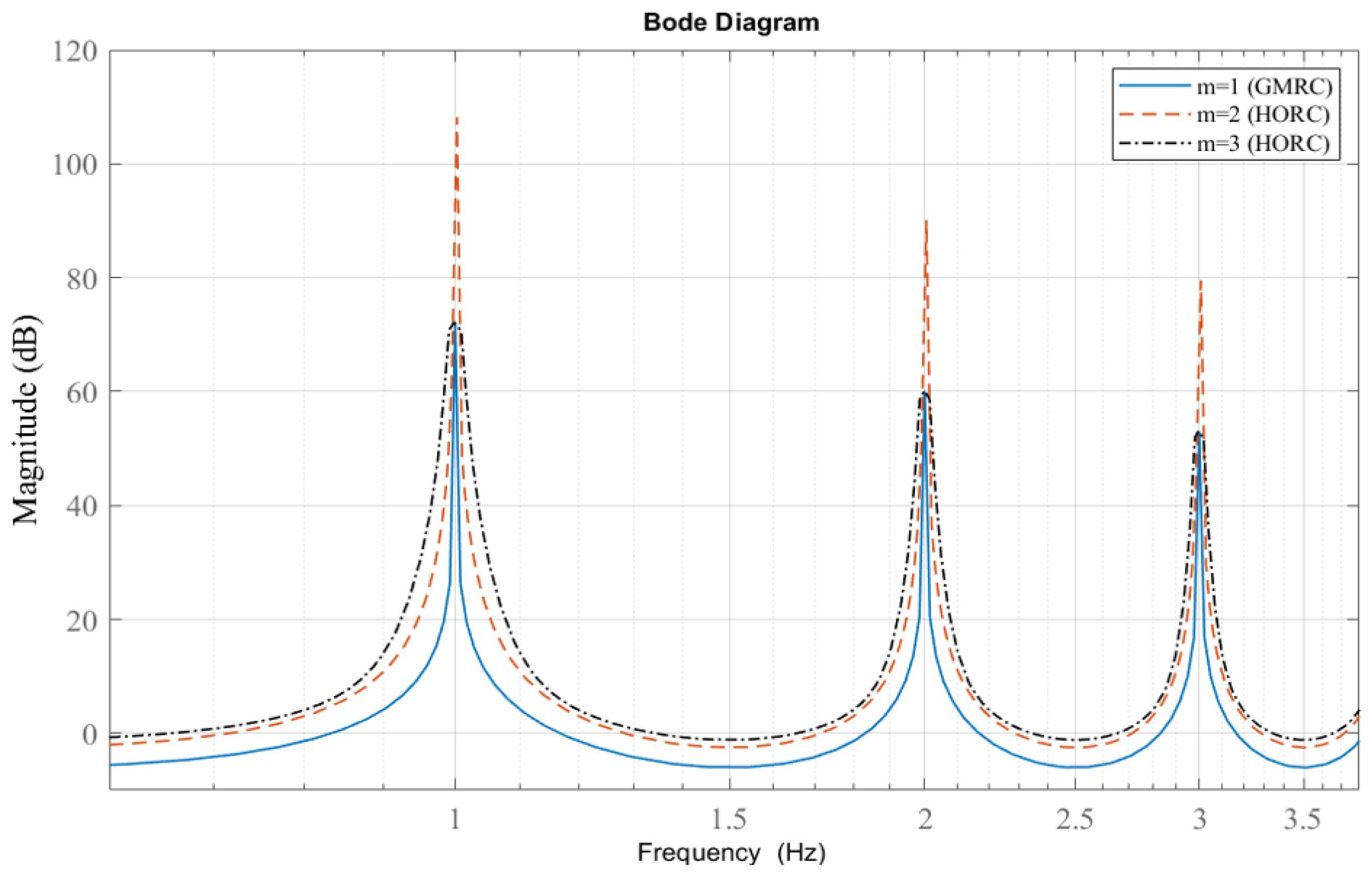
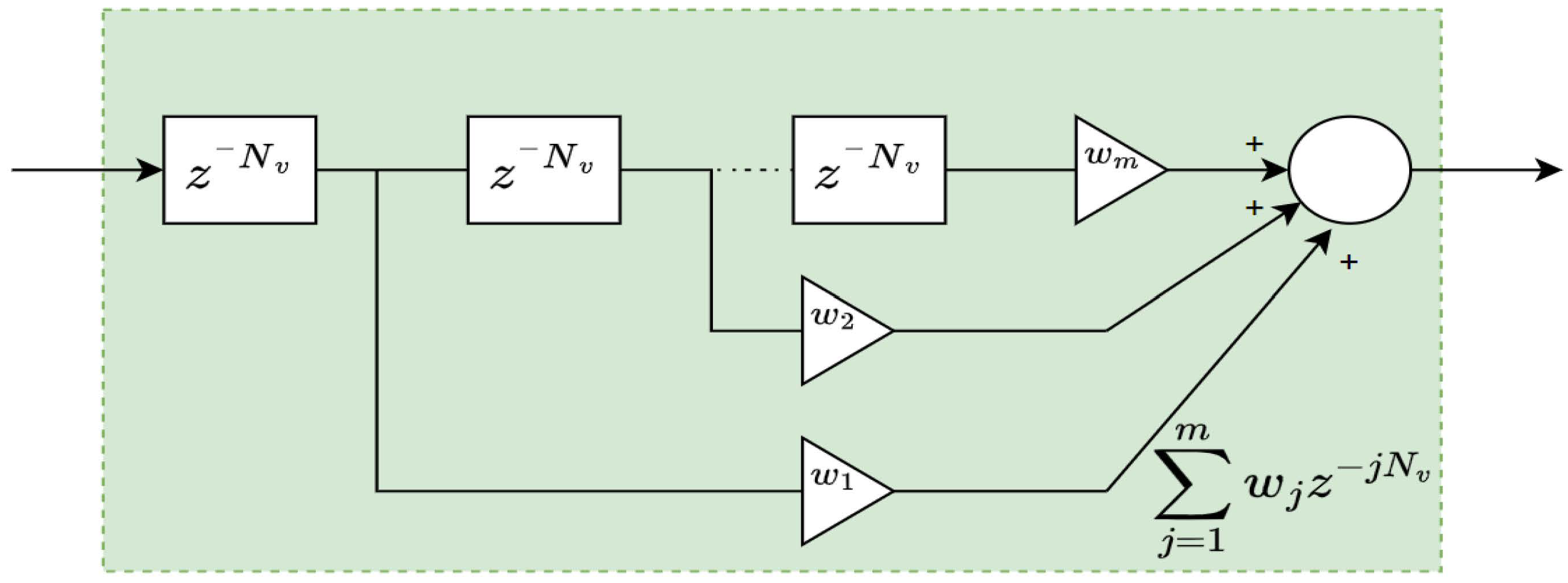
3.2. A Higher-Order Modified RC
Here, the control problem for the LTI system (1) is disturbance rejection only, implying that the reference is set to zero. The following input–output relation expresses a discrete-time higher-order modified repetitive controller (HOMRC) []:
where is a control input generated by HOMRC, is the q-filter used for cutting off higher frequencies of the disturbance , is the stabilizing controller, and is the number of samples per disturbance period. In contrast with (5), is an integer number given by
where is a nominal disturbance period which is also known based on Assumption 2.
Similar to (4), we also determine the internal model of the HOMRC given by
It can be seen from (11) that HOMRC employs a sum of the weighted delays, i.e, . The weights for are chosen to satisfy conditions as follows []:
The conditions (12) and (13) are added to ensure that the high gains of HOMRC at the fundamental frequency and its harmonics remain infinite. In addition, the high-gain peaks of HOMRC at the harmonics are extended to wider regions. This behavior can be seen from the magnitude responses of GMRC and HOMRC at the targeted fundamental frequency 1 Hz shown in Figure 1. Hence, the disturbance-rejection performances at the neighboring frequencies are improved by using the HOMRC.

Figure 1.
Magnitude responses of the GMRC and the HOMRC.
4. Proposed Dual Internal Model-Based RC (DIMRC)
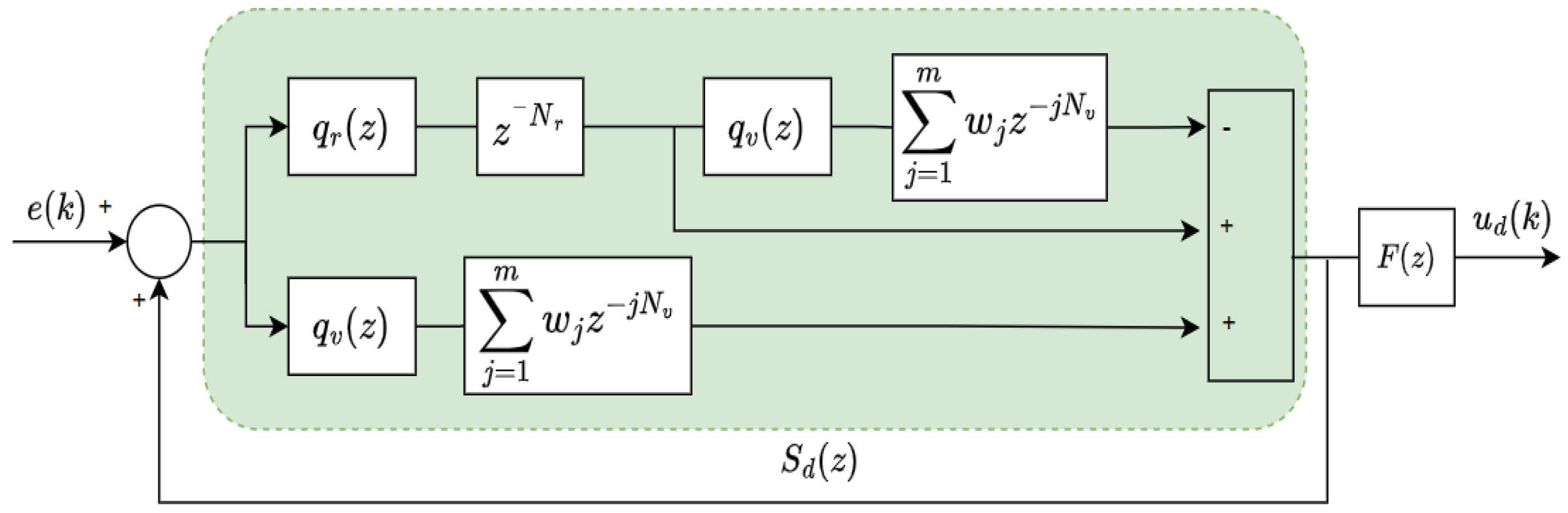
4.1. DIMRC Structure
Observing the internal models (8) and (11), we notice that both models show a similar form as follows:
where corresponds to the delay term of GMRC/HOMRC, and formulated by
Hence, the proposed DIMRC is designed to have the following transfer function:
which is equivalent to the DIMRC law as follows:
Note that in (17) is the delay term constructed based on the denominators and given in (8) and (11), respectively. The is also in the form of polynomial and is proposed as follows:
Finally, the block diagram of the proposed DIMRC closed-loop system is illustrated in Figure 2. In addition, the controller realization is described in Figure 3. The weighted delays shown in Figure 3, is then detailed in Figure 4. Note that the controller realization shown in Figure 3 is implementable for DIMRC with causal or proper stabilizing controller . Some designs resulting in causal form can be seen in [,]. Here, the causal stabilizing controller can be implemented separately without being merged with the internal model. Other designs resulting in non-causal/improper form can be found in the references [,,]. Thus, it is obvious that the stabilizing controller can be designed in either causal or non-causal form. Suppose that the stabilizing controller is non-causal by a factor of . This means that and , where and represent the degrees of ’s numerator and denominator , respectively. To reduce the controller’s complexity, the realization of DIMRC with non-causal can be achieved by modifying Figure 3 into Figure 5.

Figure 2.
Block diagram of the plug−in DIMRC system.

Figure 3.
Realization of the proposed DIMRC.

Figure 4.
Realization of the weighted multiple delays.

Figure 5.
Realization of the DIMRC with non−causal stabilizing controller.
4.2. Stability of the Plug-In RC System
In this subsection, we develop a sufficient stability condition for the closed-loop system regulated by plug-in DIMRC. The sensitivity function of the plug-in DIMRC system shown in Figure 2 is given by
Equation (23) can be factorized to
Let define the closed-loop plant model as follows:
The sensitivity function (24) can be further derived to
This leads to the following characteristic equation (CE):
Based on (27), the closed-loop DIMRC system in Figure 2 is internally stable if the following two conditions are fulfilled:
- The second factor in (27) has stable roots. Following the work in [], the stability of the second part can be assured byHere, the notation corresponds to the -norm infinity of the transfer function , which can be defined as the peak of the magnitude response of for all frequency components.
Based on Assumption 1 and picking the conventional controller , can be computed. Meanwhile, can be calculated by using Assumption 2, and by choosing the q-filters and . Finally, the stabilizing controller can be designed to satisfy the condition (28). It has been mentioned before that several works addressing stabilizing controller design methods can be found in [,,,,,]. Here, we omit the discussion about the stabilizing controller design as we focus on the internal model structure, the controller structure and realization, and the stability of the plug-in DIMRC system.
To summarize, the proposed design is accomplished according to the following steps:
- Obtain the open-loop plant model (2).
- Pick the conventional controller , ensuring a stable (25).
- Choose the order of HOMRC m, and determine the weights based on (12) and (13).
- Construct the by using (21).
- Determine the stabilizing controller satisfying (28).
- Synthesize the complete controller according to (17).
5. Simulation Results
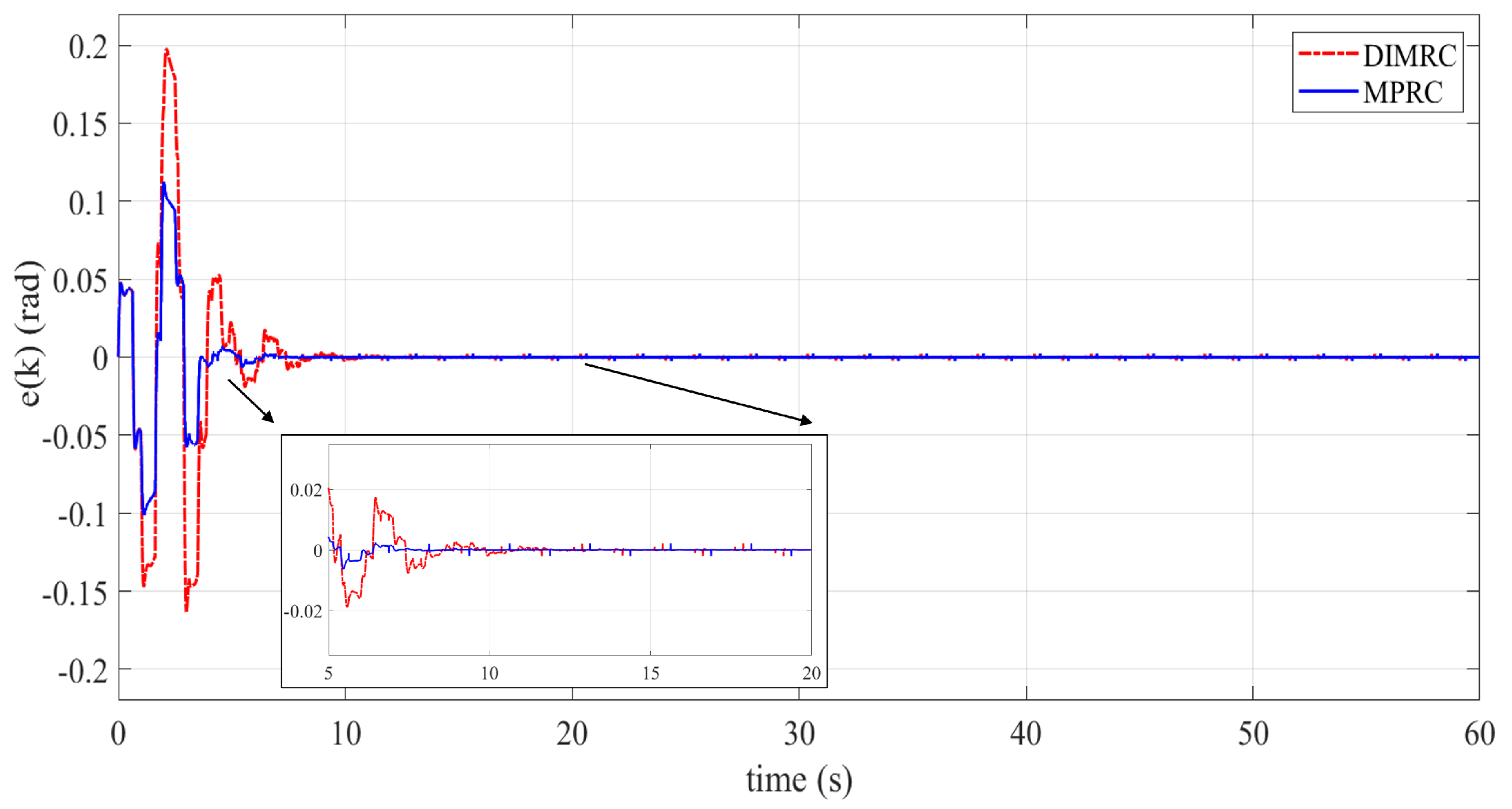
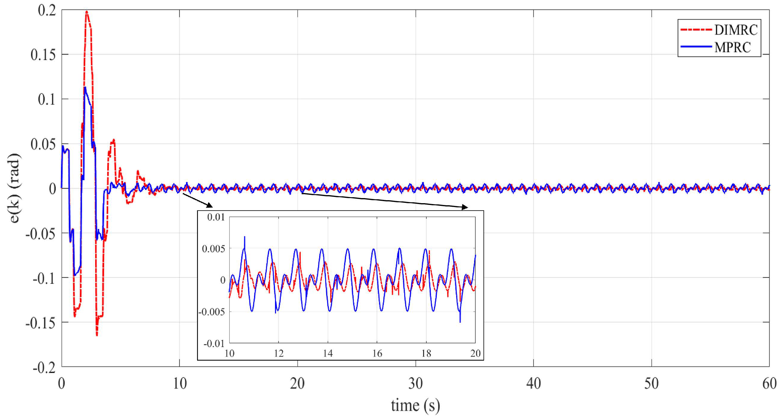
5.1. Case 1: Minimum Phase Stabilized System
To validate the effectiveness of the proposed controller, the following discrete-time model of Quanser SRV02 servo plant [] is used in the simulation:
where is an open-loop plant model, is an angle position (rad), and is an input voltage (Volt). The open-loop plant (29) is associated with the sampling time s. The conventional controller used to stabilize the open-loop plant (29) is a proportional controller with the gain 10, i.e., . The stabilized plant model (25) is obtained as follows:
The stabilized plant model (30) has a stable zero and two stable poles located at , , and . Thus, the model (30) is classified as the minimum-phase system. The control objective is to track a periodic triangle reference with the fixed fundamental frequency Hz and to suppress the uncertain periodic disturbance with known nominal frequency as Hz. We can notice that and are uncorrelated, which is inline with Assumption 3. The reference is illustrated in Figure 6. The integer numbers and can be calculated as follows:

Figure 6.
Repetitive reference .
Suppose that the q-filters and are equally chosen as
The chosen filter above gives the tracking/rejection performance with a bandwidth of Hz. Note that the q-filter here determines the bandwidth, which selects the reference frequencies to be passed and the disturbance frequencies to be attenuated. The coefficients of the q-filter are calculated according to (6) and (7) to give a unity gain at the targeted bandwidth and a zero phase to all frequency components. The filter behaviors can be seen in Figure 7. Increasing the filter’s degree does not guarantee that the bandwidth is enlarged. The coefficients must be carefully tuned to give the preferred bandwidth. Here, the chosen q-filter already accommodates the targeted reference and disturbance frequencies, as specified before.

Figure 7.
Magnitude and phase responses of the q−filter (32).
Let us pick the order of HOMRC m as 2. Then, the following weights are chosen to satisfy conditions (12) and (13):
Based on (31) and (33), the polynomial in (21) can now be synthesized. Next, we need to obtain to stabilize the closed-loop DIMRC system. A straightforward design for is
where is the learning gain and is the inverse model of (30). It can be seen that is non-causal by a factor of 1 (). Hence, the proposed DIMRC can be realized by following the controller structure shown in Figure 5. The learning gain satisfying condition (28) is chosen as . As we have and , the proposed DIMRC (17) can now be constructed.
To highlight the tracking performance of the proposed DIMRC, a comparison to multiple-periods RC (MPRC) [] is conducted for two different disturbance models as follows:
The MPRC law [] is expressed as
where and are provided in (31), is given in (34), and is a polynomial given by
Tracking-error performance of both DIMRC and MPRC for the minimum-phase system (30) with disturbance model is shown in Figure 8. We can notice that the tracking errors of both DIMRC and MPRC converge to zero steady-state value. This is obvious because the disturbance model represents the periodic disturbance signal with nominal fundamental frequency as 1 Hz. Figure 8 also indicates that the MPRC outperforms the DIMRC in terms of convergence rate. This phenomenon can be understood because the DIMRC applies a longer control delay due to the use of the higher-order internal model. The control delay (also referred as delay term) of DIMRC is calculated according to (21), and given by

Figure 8.
Tracking errors for the minimum phase system (30) with the disturbance model .
Meanwhile, the control delay of MPRC is obtained from (38), and expressed as
We can observe from (39) and (40) that DIMRC has more series of delays and gives longer delays to the control input and the tracking error. Consequently, the DIMRC takes longer to generate the correct control input, so the tracking error converges to a steady state. However, we mainly focus on improving the tracking accuracy, especially during the steady state of the plant under time-varying periodic disturbances. Therefore, the superior performance of DIMRC can be seen from the next simulation results.
Next, we examine the performance of both controllers when the disturbance frequencies vary from their nominal values. The model (36) represents the uncertain exogenous periodic disturbance where the frequency components are shifted to Hz and Hz. Figure 9 illustrates the tracking errors of the minimum-phase system (30) with disturbance model . As we observe in Figure 9, the transient errors of both controllers indicate similar patterns to the ones shown in Figure 8. In contrast, the steady-state errors are significantly different, showing that zero-error steady state is no longer achieved. These results illustrate that RC systems’ tracking accuracy is greatly affected when the disturbance’s frequency is slightly changed from its nominal value. However, the steady-state error of DIMRC is significantly smaller than that of MPRC. This implies that DIMRC exploiting the higher-internal model offers better robustness against the uncertain periodic disturbance, especially during the steady-state period. This performance can also be assessed from the magnitude responses of the simulated DIMRC and MPRC shown in Figure 10. We notice that the magnitude responses at the reference frequency ( Hz) are almost similar between DIMRC and MPRC. However, the magnitude response of the DIMRC is extended to a larger region around the nominal disturbance frequency (1 Hz). As a result, the DIMRC improves the rejection performance at the neighboring disturbance frequencies. Therefore, when the disturbance frequencies vary to Hz and Hz, the DIMRC gives a better attenuation than the MPRC, resulting in a smaller steady-state error.

Figure 9.
Tracking errors for the minimum phase system (30) with the disturbance model .

Figure 10.
Magnitude responses of the simulated DIMRC and MPRC.
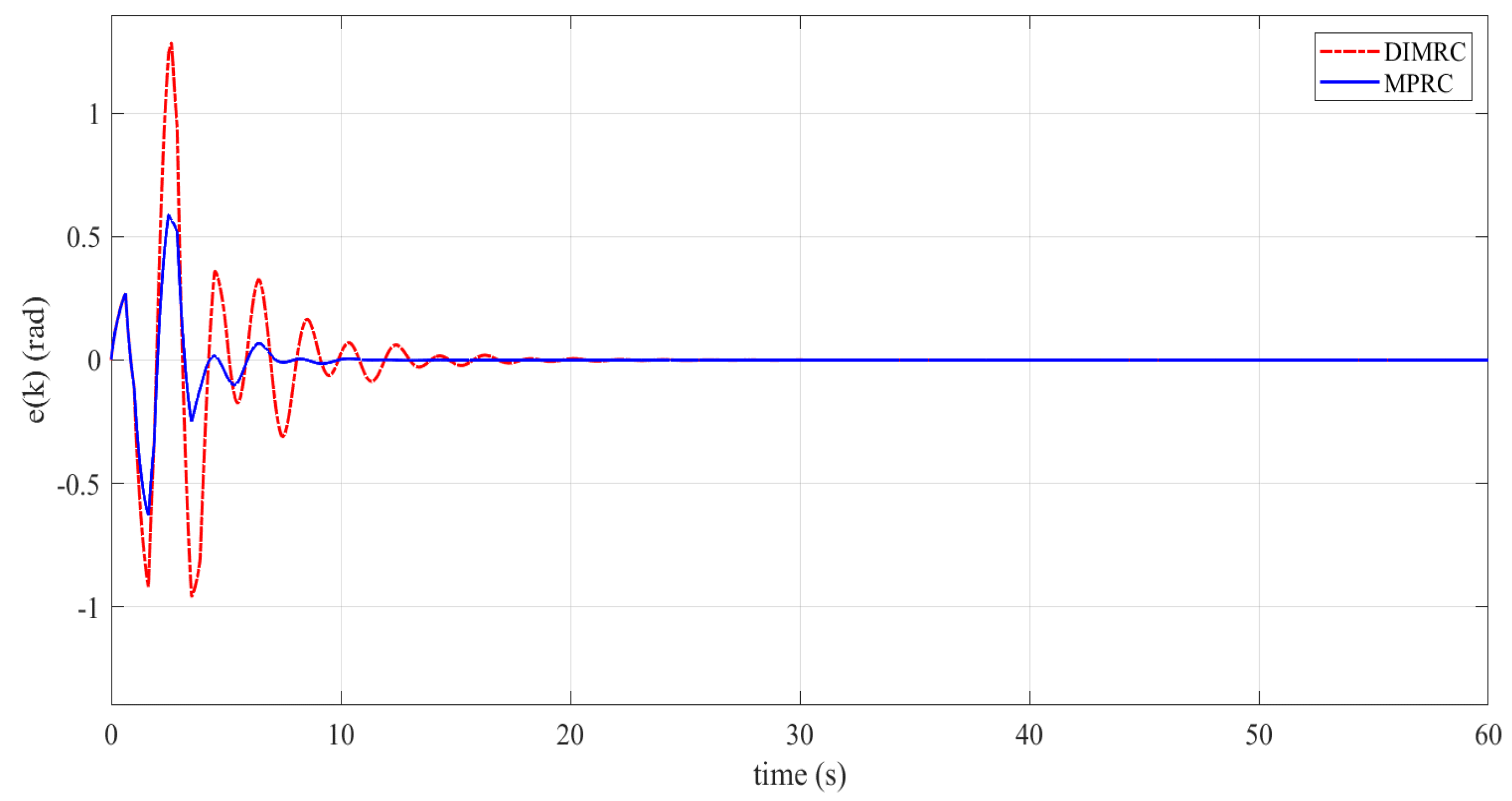
5.2. Case 2: Non-Minimum Phase Stabilized System
In this case, the open-loop plant model (29) is stabilized using the conventional controller as follows:
The resulting close-loop plant model is
The closed-loop plant model (42) has three poles given by , , , and two zeros located at , and . It is obvious that the model (42) has stable poles and one unstable zero () confirming that (42) is a stable non-minimum phase system. Note that the stabilizing controller designed according to (34) is not applicable to the non-minimum phase system. The design method (34) results in unstable stabilizing controller . In this case, we employ a zero-phase tracking error controller (ZPETC) design technique developed in []. The ZPETC-based stabilizing controller has the following transfer function:
Here, is the learning gain similar to the ones in (34), is the stabilized-plant gain, denotes the denominator of (42), and represent stable and unstable factors of , where is the numerator of (42). The term is obtained from with the operator z replaced by the backward shift operator . Using the Equation (43) and choosing the learning gain as , we obtain expressed as
We notice that the above is non-causal by a factor of 2. This gives as 2, and the DIMRC structure can be adjusted according to Figure 5.
The tracking-error performance of the non-minimum phase system (42) for two different disturbance models and are, respectively, depicted in Figure 11 and Figure 12. From Figure 11 and Figure 12, we notice that the DIMRC system converges more slowly and exhibits larger peaks of the tracking error during transience compared to the MPRC system. However, when the disturbance model is uncertain, the DIMRC system offers better steady-state error. These results indicate that, in term of the transient responses, the MPRC outperforms the DIMRC for both minimum and non-minimum phase systems when there is no variation in the disturbance model. Nevertheless, when the disturbance model slightly changes from its nominal value, the DIMRC significantly outperforms the MPRC, especially during the steady-state period.

Figure 11.
Tracking errors for the non-minimum phase system (42) with the disturbance model .

Figure 12.
Tracking errors for the non-minimum phase system (42) with the disturbance model .
In order to highlight the controllers’ performance during the steady state, the detailed comparison in terms of the steady-state time () and root-mean-square of the steady-state error (rms-) are summarized in Table 1. The is defined as the time needed to reach error (). Meanwhile, the rms- is calculated by
where , , and is the simulation period. It can be seen from Table 1 that the proposed method has a smaller mean square error for both minimum and non-minimum phase systems under uncertain periodic disturbance . However, the proposed controller offers longer steady-state time compared to the MPRC. All these results indicate that the proposed controller provides better robustness against uncertain periodic disturbances, but at the expense of a slower transient response.

Table 1.
Steady-state performance of the DIMRC and MPRC.
6. Conclusions
In this paper, the dual internal model-based repetitive controller has been developed to simultaneously track repetitive tasks and reject uncertain periodic disturbances. The proposed design combines two internal models originating from the general modified and high-order modified repetitive control schemes. The internal model of general modified repetitive control is adopted to handle periodic reference tracking with a fixed frequency. Then, the internal model of high-order modified repetitive control is added to deal with the uncertain periodic disturbance. The controller structure, stability analysis, and controller realization are discussed in this article. Simulation and comparison studies have been conducted to highlight the tracking performance of the proposed controller. However, the proposed design is still limited for the single-input single-output system, implying that the controller is not applicable for the multivariable system. Moreover, the proposed control scheme is unsuitable for handling non-periodic (aperiodic) disturbances. Extending the proposed work for the multivariable system and for handling non-periodic disturbances are challenging tasks and have become our future research investigation.
Author Contributions
Conceptualization, J.A.P. and P.P.; methodology, E.K. and J.A.P.; software, P.P.; validation, E.B.P. and D.R.; formal analysis, E.K.; investigation, E.B.P. and P.P.; resources, S.W. and T.M.; data curation, J.A.P.; writing—original draft preparation, J.A.P.; writing—review and editing, E.K.; visualization, D.R.; supervision, P.P. and S.W.; project administration, T.M. and F.S.; funding acquisition, F.S. All authors have read and agreed to the published version of the manuscript.
Funding
The authors received financial support for publication from the UPLAND Project, with the support of IsDB and IFAD, that focus to increase smallholders’ agriculture productivity, incomes, livelihoods, and resilience in the targeted area. Meanwhile, the research was supported by Research Center for Photonics, National Research and Innovation Agency (BRIN), Indonesia.
Institutional Review Board Statement
Not applicable.
Informed Consent Statement
Not applicable.
Data Availability Statement
Not applicable.
Acknowledgments
The authors would like to express sincere thanks, particularly to Rahmanto, the Director of Agriculture Irrigation at the Ministry of Agriculture, Republic of Indonesia.
Conflicts of Interest
The authors declare no conflict of interest.
Abbreviations
The following abbreviations are used in this manuscript:
DIMRC | Dual internal model-based repetitive controller. |
GMRC | General modified repetitive controller. |
HOMRC | Higher-order modified repetitive controller. |
LTI | Linear time invariant. |
MPRC | Multi-Periods Repetitive Control. |
RC | Repetitive controller. |
ZPETC | Zero-phase tracking error controller. |
References
- Francis, B.A.; Wonham, W.M. The internal model principle for linear multivariable regulators. Appl. Math. Optim. 1975, 2, 170–194. [Google Scholar] [CrossRef]
- Hillerstrom, G.; Walgama, K. Repetitive control theory and applications—A survey. In Proceedings of the 13th IFAC World Congress, San Francisco, CA, USA, 30 June–5 July 1996; pp. 1–6. [Google Scholar]
- Kurniawan, E.; Cao, Z.; Mahendra, O.; Wardoyo, R. A survey on robust Repetitive Control and applications. In Proceedings of the 2014 IEEE International Conference on Control System, Computing and Engineering, Penang, Malaysia, 28–30 November 2014; pp. 524–529. [Google Scholar]
- Liu, Y.; Wu, P.; Ferrari, R.M.G.; Van Wingerden, J.W. Fast adaptive fault accommodation in floating offshore wind turbines via model-based fault diagnosis and subspace predictive repetitive control. IFAC-PapersOnLine 2020, 53, 12650–12655. [Google Scholar] [CrossRef]
- Meng, F.; Zhang, X.; Li, Z.; Wen, X.; You, L. Speed Fluctuation Suppression for the Inverter Compressor Based on the Adaptive Revised Repetitive Controller. Energies 2020, 13, 6342. [Google Scholar] [CrossRef]
- Cui, P.; Zhang, G. Modified Repetitive Control for Odd-Harmonic Current Suppression in Magnetically Suspended Rotor Systems. IEEE Trans. Ind. Electron. 2019, 66, 8008–8018. [Google Scholar] [CrossRef]
- Page, A.P.; Freeman, C.T. Point-to-point repetitive control of functional electrical stimulation for drop-foot. Control Eng. Pract. 2020, 96, 1–10. [Google Scholar] [CrossRef]
- Li, L.; Aphale, S.S.; Zhu, L. Enhanced odd-harmonic repetitive control of nanopositioning stages using spectrum-selection filtering scheme for high-speed raster scanning. IEEE Trans. Automat. Sci. Eng. 2021, 18, 1087–1096. [Google Scholar] [CrossRef]
- Cai, K.; Deng, Z.; Peng, C.; Li, K. Suppression of Harmonic Vibration in Magnetically Suspended Centrifugal Compressor Using Zero-Phase Odd-Harmonic Repetitive Controller. IEEE Trans. Ind. Electron. 2020, 67, 7789–7797. [Google Scholar] [CrossRef]
- Nakano, M.; Hara, S. Microprocessor-based repetitive control. Microprocess. Based Control Syst. 1986, 4, 279–296. [Google Scholar]
- Chew, K.-K.; Tomizuka, M. Steady-state and stochastic performance of a modified discrete-time prototype repetitive controller. Trans. ASME J. Dyn. Syst. Meas. Contr. 1990, 112, 35–41. [Google Scholar] [CrossRef]
- Hillerstrom, G.; Sternby, J. Repetitive control using low order models. In Proceedings of the American Control Conference, Baltimore, MD, USA, 29 June–1 July 1994; Volume 2, pp. 1873–1878. [Google Scholar]
- Grino, R.; Costa-Castello, R. Digital repetitive plug-in controller for odd-harmonic periodic references and disturbances. Automatica 2005, 41, 153–157. [Google Scholar] [CrossRef]
- Kurniawan, E.; Afandi, M.I.; Suryadi, S. Repetitive control system for tracking and rejection of multiple periodic signals. In Proceedings of the International Conference on Robotics, Automation and Sciences (ICORAS), Melaka, Malaysia, 27–29 November 2017; pp. 1–5. [Google Scholar]
- Steinbuch, M.; Weiland, S.; Singh, T. Design of Noise and Period-time Robust High-order Repetitive Control, with Application to Optical Storage. Automatica 2007, 43, 2086–2095. [Google Scholar] [CrossRef]
- Huang, W.-W.; Hu, C.; Zhu, L.-M. Robust Repetitive Control of Nanopositioning Stages Using the Spectrum-Selection Filter with Narrow Passbands. IEEE/ASME Trans. Mechatron. 2022, 27, 4211–4216. [Google Scholar] [CrossRef]
- Tian, M.; Wang, B.; Yu, Y.; Dong, Q.; Xu, D. Discrete-Time Repetitive Control-Based ADRC for Current Loop Disturbances Suppression of PMSM Drives. IEEE Trans. Ind. Inform. 2022, 18, 3138–3149. [Google Scholar] [CrossRef]
- Jamil, M.; Waris, A.; Gilani, S.O.; Khawaja, B.A.; Khan, M.N.; Raza, A. Design of Robust Higher-Order Repetitive Controller Using Phase Lead Compensator. IEEE Access 2020, 8, 30603–30614. [Google Scholar] [CrossRef]
- Lu, W.; Wang, W.; Zhou, K.; Fan, Q. General High-Order Selective Harmonic Repetitive Control for PWM Converters. IEEE J. Emerg. Sel. Top. Power Electron. 2022, 10, 1178–1191. [Google Scholar] [CrossRef]
- Duan, C.; Gu, G.; Du, C.; Chong, T.C. Robust Compensation of Periodic Disturbances by Multirate Control. IEEE Trans. Magn. 2008, 44, 413–418. [Google Scholar] [CrossRef]
- Yang, R.; Wang, M.; Li, L.; Wang, G.; Zhong, C. Robust Predictive Current Control of PMLSM With Extended State Modeling Based Kalman Filter: For Time-Varying Disturbance Rejection. IEEE Trans. Power Electron. 2020, 35, 2208–2221. [Google Scholar] [CrossRef]
- Landau, I.D.; Constantinescu, A.; Rey, D. Adaptive narrow band disturbance rejection applied to an active suspension—An internal model principle approach. Automatica 2005, 41, 563–574. [Google Scholar] [CrossRef]
- Zhao, R.; Xie, W.; Yu, G.; Wang, G.; Wong, P.K.; Silvestre, C. Adaptive ride height controller design for vehicle active suspension systems with uncertain sprung mass and time-varying disturbance. Int. J. Robust Nonlinear Control 2022, 32, 5950–5966. [Google Scholar] [CrossRef]
- Manayathara, T.J.; Tsao, T.-C.; Bentsman, J. Rejection of unknown periodic load disturbances in continuous steel casting process using learning repetitive control approach. IEEE Trans. Control Syst. Technol. 1996, 4, 259–265. [Google Scholar] [CrossRef]
- Ma, Z.; Fang, Y.; Zheng, H.; Liu, L. Active Disturbance Rejection Control With Self-Adjusting Parameters for Vibration Displacement System of Continuous Casting Mold. IEEE Access 2019, 7, 52498–52507. [Google Scholar] [CrossRef]
- Tomizuka, M. Zero phase error tracking algorithm for digital control. Trans. ASME J. Dyn. Syst. Meas. Contr. 1987, 109, 65–68. [Google Scholar] [CrossRef]
- Kurniawan, E.; Adinanta, H.; Harno, H.G.; Prakosa, J.A.; Suryadi, S.; Purwowibowo, P. On the synthesis of a stable and causal compensator for discrete-time high-order repetitive control systems. Int. J. Dynam. Control 2021, 9, 727–736. [Google Scholar] [CrossRef]
- Kurniawan, E.; Cao, Z.; Man, Z. Design of Robust Repetitive Control with Time-Varying Sampling Periods. IEEE Trans. Ind. Electron. 2014, 61, 2834–2841. [Google Scholar] [CrossRef]
- Xu, K.; Longman, R.W. Use of Taylor Expansions of The Inverse Model to Design FIR Repetitive Controllers. In Spaceflight Mechanics; Advances in the Astronautical Sciences Series; American Astronautical Society: Springfield, VA, USA, 2009; Volume 134, pp. 1073–1088. [Google Scholar]
- Zhang, B.; Wang, D.; Zhou, K.; Wang, Y. Linear Phase Lead Compensation Repetitive Control of a CVCF PWM Inverter. IEEE Trans. Ind. Electron. 2008, 55, 1595–1602. [Google Scholar] [CrossRef]
- Prasitmeeboon, P.; Longman, R.W. Repetitive Control Compensator Design for Frequency Response near Singularities. J. Astronaut. Sci. 2021, 68, 916–945. [Google Scholar] [CrossRef]
- Kurniawan, E. Robust Repetitive Control and Applications. Ph.D. Thesis, Swinburne University of Technology, Hawthorn, Australia, 2013. [Google Scholar]
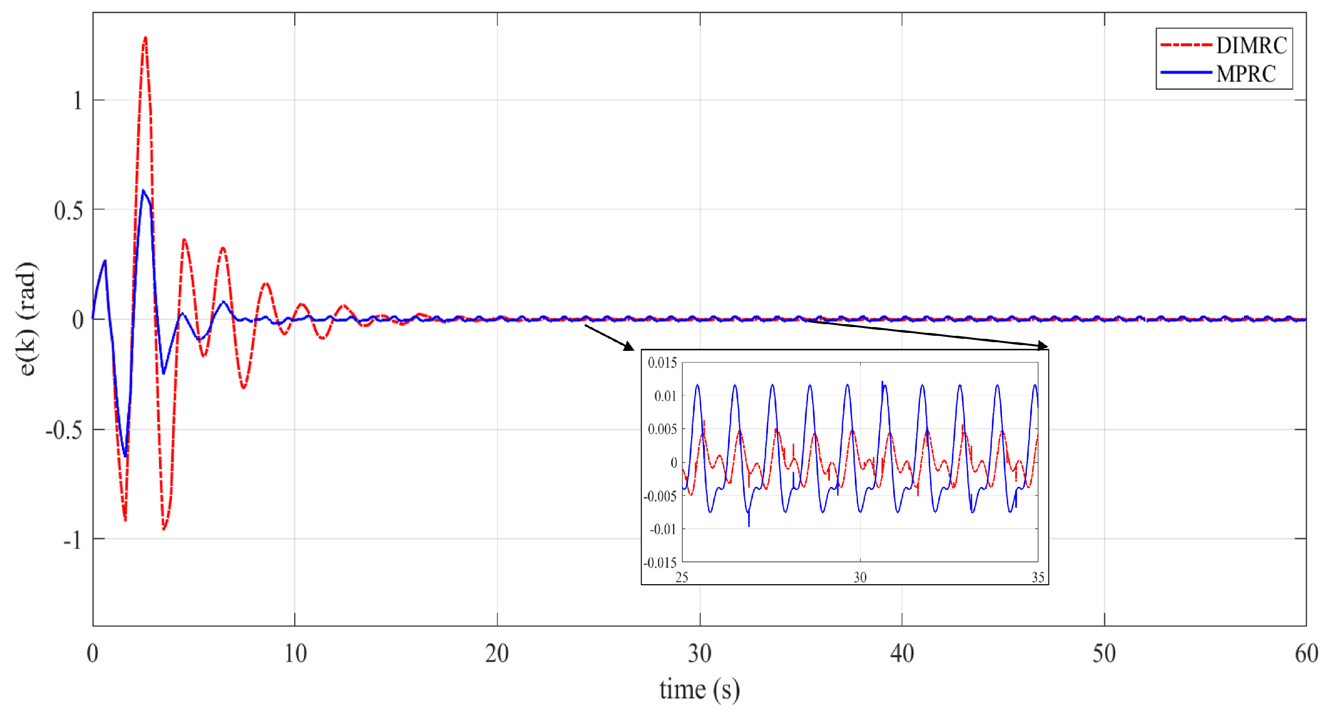
Publisher’s Note: MDPI stays neutral with regard to jurisdictional claims in published maps and institutional affiliations. |
© 2022 by the authors. Licensee MDPI, Basel, Switzerland. This article is an open access article distributed under the terms and conditions of the Creative Commons Attribution (CC BY) license (https://creativecommons.org/licenses/by/4.0/).