Article

Influence of Bends in the Functionality of Passive Explosion Isolation Valves

by
Ignacio Garrido-Ceca
1,2,*,
María Puig-Gamero
1 and
Álvaro Ramírez-Gómez
3
1
Adix Ingeniería, CM-42. Salida 118, Vía de Servicio Dirección Toledo Km 2, 13700 Tomelloso, Spain
2
Universidad Politécnica de Madrid, C/Ramiro de Maeztu 7, 28040 Madrid, Spain
3
Departamento de Ingeniería Mecánica, Química y Diseño Industrial, Universidad Politécnica de Madrid, Ronda de Valencia, 28012 Madrid, Spain
*
Author to whom correspondence should be addressed.
Appl. Sci. 2022, 12(22), 11654; https://doi.org/10.3390/app122211654
Submission received: 20 October 2022 / Revised: 11 November 2022 / Accepted: 12 November 2022 / Published: 16 November 2022
(This article belongs to the Section Applied Industrial Technologies)

Abstract

:
Explosion isolation flap valves are one of the most used explosion protection systems in process industries; research is essential to improve them and to minimise both human and material losses when dust explosions take place. In this regard, there is little knowledge on the effect of bends in the functionality of these protective systems; hence, the main aim of this work is to bridge this gap. Large-scale dust explosions were performed, using three different types of dust: metal dust and two types of organic dust. In order to analyse the effect of bends in the functionality of these protective systems, results using a straight duct and one with bends were compared for each dust tested. In addition, the influence of the bend radius on aluminium dust explosions was also evaluated. The results indicated that the effect of bends depended on the explosive characteristics of the dust. However, for aluminium and maize starch dusts, bends led to higher pressures and flame velocities. Relevant information is provided to help decision-making when designing these valves. Moreover, such data can be used for consideration in the discussions held by the task force entrusted with developing the standard used to assess their functionality.

1. Introduction

Despite the progress made in recent decades, dust explosions still occur in industry [1,2,3,4,5,6]. One of the most dangerous aspects of dust explosions is its propagation through ducts to other industrial equipment, the consequences of which can be catastrophic. Nowadays, research is still needed to understand the propagation process of explosions, to analyse the different influencing factors and assess risks, so that when there is an explosion, the blast does not affect other process areas.
Explosions depend on multiple factors [7], such as the volume of the enclosure where it occurs, location of the ignition source, type of dust, concentration, etc. [6,8], but most of all, turbulence is the factor that still needs better understanding [9]. There are several options for protecting against dust explosions. The most widely used technical solution for protecting equipment or facilities, by reducing the potential overpressure, is venting. This is probably due to its simple and effective design and apparently relatively low cost [10,11,12]. However, if isolation from the explosion is needed, then flap valves are one of the most widely used protection systems (Figure 1).
These valves are designed to prevent the propagation of a dust explosion towards other areas of the industrial plant through ducts that are connected to the equipment or installation where the explosion occurs [13]. They remain open when the industrial plant is operating normally; only in the event of an explosion does the pressure wave generated cause it to close (see Figure 1). In Europe, these protective systems need to be certified according to the standard EN16447 to ensure that they meet the minimum requirements regarding its intended use. If these are met, then they may be distributed in the European market [13]. Nowadays, there is a dearth of data on how bends in ducts influence the propagation of dust explosions and the functions that these protective systems have. The presence of bends could introduce more turbulence, accelerate the flames and affect the functionality of the protective system against the dust explosion. In the literature, there are a few studies in this regard, and considerable debate on the influence bends have. For instance, Pu et al., studied the effect of flow obstacles on how the blast from dust explosions spread, and observed that they accelerated the flame and increased explosion pressure [14]. Phylaktou et al. also found that the flame propagation speed rose four-fold when bends were used [15]. However, the opposite effect was found by Zhu et al., who carried out experiments using different angles, and detected that the flame speed decreased significantly as it went around the bends [16].
However, it should be stressed that plenty of experimental research conducted on dust explosions are being carried out on a laboratory scale, where the operating conditions and variables are assumed to remain constant and are thus easier to control. However, and although economic and technical complexities are usually introduced, in order to scale up these laboratory results, more large-scale experimental studies are still needed. In this research, dust explosions have been developed on a large-scale using a DN500 flap valve, to help make decisions when designing these passive explosion isolation valves. This information could also be taken into consideration for the discussions established in the working group in charge of the revision of the standard EN16447.

2. Materials and Methods

2.1. Materials

In this research, aluminium dust (Al), maize starch (MS) and wheat flour (WF), were selected and tested. These dusts present different reactivity and explosion severity; they can be classified as St1 (WF), St1 (MS) and St3 (Al). Samples of these materials were previously oven-dried to remove moisture and sieved before characterisation. The reactivity parameters Kst and Pmax were characterised according to EN 14034-2:2006+A1:2011 and EN 14034-1:2005+A1:2011, respectively [17,18]. Kst can be defined as the highest rate of pressure rise obtained during the explosion, and the Pmax is the highest explosion pressure developed. Both are explosive properties measured in the laboratory at the optimum dust concentration to quantify the severity of a dust explosion [19]. The result from their characterisation is shown in Table 1.

2.2. Experimental Setup

Figure 2 shows the experimental test setup used in this work, the aim of which is to reflect the specified intended use of the flap valve. This includes the minimum volume of the enclosure that can be protected, the geometrical configuration of the duct and the distance for installing the flap valve. In this research, three bends in the duct were included in order to evaluate their influence on explosion propagation and the functionality of the flap valve (Table 2 and Table 3). Tests were carried out using:
  • A straight duct (Figure 3a);
  • A curved duct using three 90° bends with a R/D (curvature radius/duct diameter) ratio of 0.6 (Figure 3b);
  • A curved duct using three 90° bends with a R/D ratio of 1.5 (Figure 3b).
Figure 3 presents a technical drawing with the different geometrical configurations of the ducts used. It also shows the location of the different sensors mounted to register flame and pressure signals. Organic and metal dust were tested to compare the results regarding the reactivity of the dust. The duct diameter was DN500. The ignition source on the 1 m3 vessel was located at a distance of halfway between duct entrance and opposite end of the test vessel, or the Z1 position according to EN 16447 [13]. In addition, in order to ensure the correct flame propagation, additional injection of dust was considered along the ducts (Figure 3).
All of the tests were recorded using a high-speed camera at 1000 frames per second allowing observation through windows of the duct of whether the flames had reached the flap valve and whether this was blocked or not.
Regarding pressure measurements, sensors were mounted in the vessel in the middle of the duct and just before the flap valve. Their exact locations are shown in Table 2 and Table 3. These were ceramic capacitive pressure sensors which can register pressures up to 2 bar, and their response time is 1 ms.
Calibration tests were performed to ensure that the flame reached the position where the flap valve was mounted. Infrared photodiodes, with response time of under 5 ms were installed at similar positions to the pressure sensors to determine the speed of the flames (Table 2 and Table 3). In every test, the flap of the valve stayed open using calibrated magnets and was then released due to the pressure produced in the dust explosion.
The total amount of dust used was 0.35 kg, 1.2 kg and 5 kg for Al, MS and WF, respectively. In every test, the dust was placed in an air-pressurised container at 20 bar. Dust injection was controlled using a solenoid valve which was operated with specific software used to run the tests automatically. The injected dust was dispersed as it passed through a nozzle.
All the dust explosions carried out were vented using venting panels mounted in the vessel on the opposite side to the duct and opened at 200 mbar (Pstat). A commercial 5 kJ pyrotechnical ignitor was used for ignition. Each test was repeated at least three times. Flame speed was obtained by measuring the time the flame needs to pass through the locations where two consecutive flame sensors were mounted and wave propagation was calculated by taking into account the time when the overpressure reached 100 mbar for each consecutive pressure sensor and the distance between them.
Finally, Table 2 and Table 3 summarise the different test configurations and measurements.

3. Results and Discussion

3.1. Influence of Bends (R/D Ratio of 0.6) on Flame Speed

Figure 4 shows the flame speed between position 1 and 2 as a function of the number of bends for wheat flour, maize starch and aluminium dusts. It can be observed that the bends led to a slight increase of the flame speed for aluminium and maize starch (from 58 ± 2 to 62 ± 3 m/s for Al and from 29 ± 9 to 37 ± 6 m/s for MS), while for wheat flour a clear downward trend was observed (from 20 ± 6 to 8 ± 2 m/s). These different trends can be explained by their different reactive properties. Regarding WF dust, this has the fewest explosive characteristics (Table 1), and hence led to a less severe explosion with lower pressure and with the flame taking longer to reach the sensor. According to Wang et al., flame speed could decrease due to the pressure drop experienced along the duct and the presence of bends [21]. Note that the pressure drop experienced with wheat flour should be more significant since the overpressures obtained were far less, due to its lower reactivity. However, for Al and MS dusts, the explosion pressure was more significant than pressure loss and thus, higher pressures were reached (Section 3.2). As mentioned above, for aluminium and maize starch, the bends caused a slight increase in the flame speed. These results concur with those published by Lin et al.; the presence of bends in the flame trajectory could cause the flow to reflect (moment in which the flow shocks the wall of the bend and changes its trajectory); therefore, a vortex could be formed [22]. In short, it can be considered as a loop; the bend can increase the flow distortion, which generates additional turbulence in turn improving the combustion of unburned particles due to the better dust/air dispersion and the more available air [23]. The rise in the mass burning rate caused an increase in the heat released which caused an expansion of combustion gases [24]. Thus, the expansion of combustion products may be related to higher flame speeds due to a release of energy and the formation of strong compression waves [25]. In addition, the dust combustion process can also be enhanced by the accumulation of unburned dust in the bend, approaching the stoichiometric concentration which would lead to a more optimal combustion process [24].
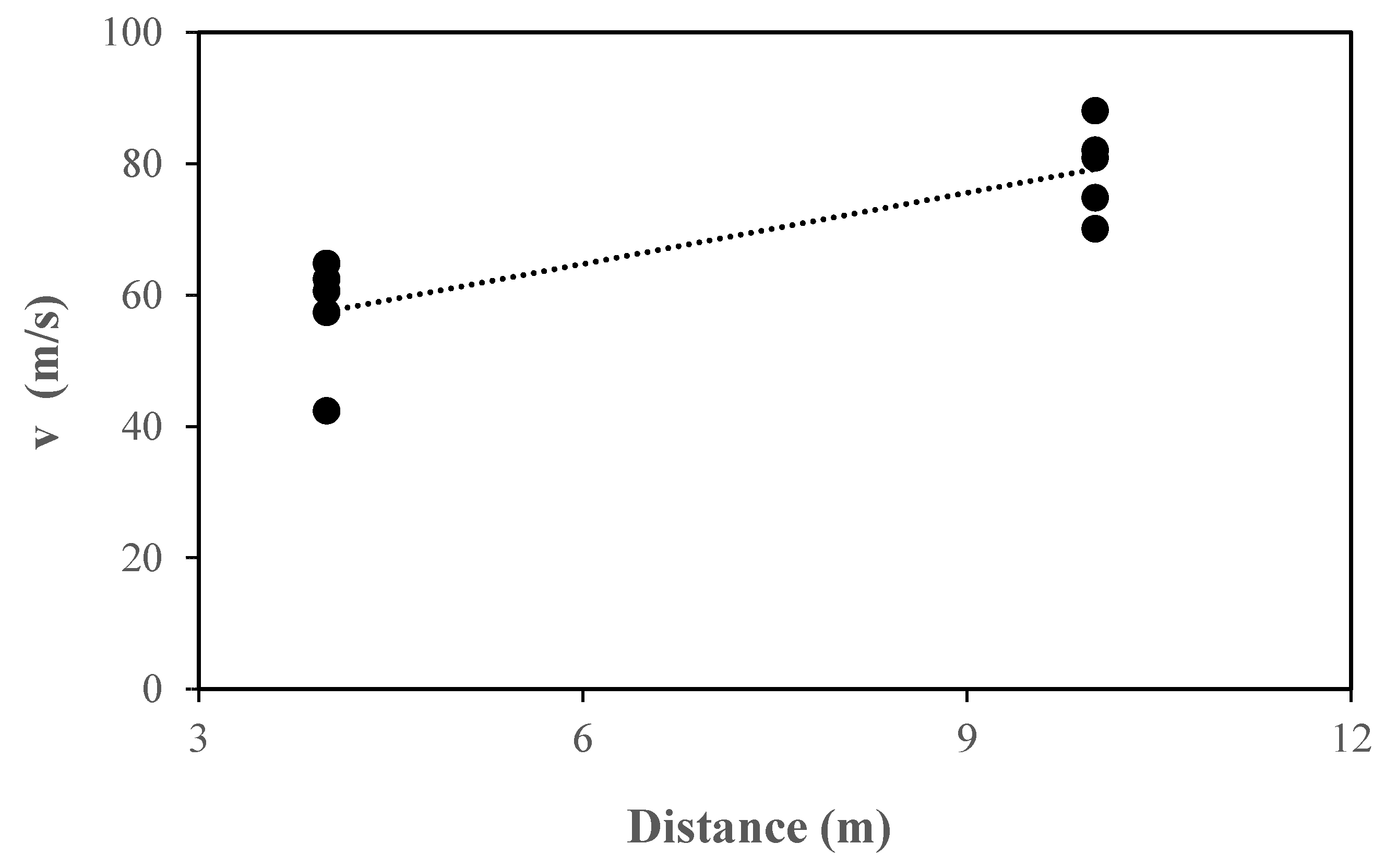
Finally, it could be observed that the highest speed of the flame was obtained with Al (62 ± 3 m/s), which is in accordance with the highest Kst (304 bar·m/s) and Pred (1253 ± 141 mbar). In addition, a stronger explosion was observed with the third flame sensor using Al dust (Figure 3). The sensor closest to the flap valve did not detect any flame when testing Al dusts using the straight duct, and when testing MS and WF for both duct configurations, thus indicating that the flame did not reach the valve. This could be related to the weaker explosion and flame reverse (when the pressure is higher in the valve than in the explosion vessel). However, the flame sensor near the flap valve detected a signal in Al dust explosions with bends. To help understand this behaviour, Figure 5 shows the trend in flame speed along the different bends. A clear and notable increase in flame speed was obtained along the duct (from 62 ± 3 to 80 ± 7 m/s) for Al dust. It can be explained as described above: an increase in turbulence could be caused by the third bend and the closing of the flap valve.
To ensure these protective systems work against explosions, the fact that the flames caused by Al dust went further (with bends) than the other ones (without bends) should be considered in their certification. This could imply that the flap valve takes too long to close and allows the flame to pass through the valve and hence the installation is not isolated. Thus, the minimum and maximum length of the flap valve installation should be carefully determined when using bends and highly reactive dusts such as Al.
Conversely, with WF dust, the closing time of the valve could be increased due to a lower pressure upstream [26].

3.2. Influence of Bends (R/D Ratio of 0.6) on Pressure

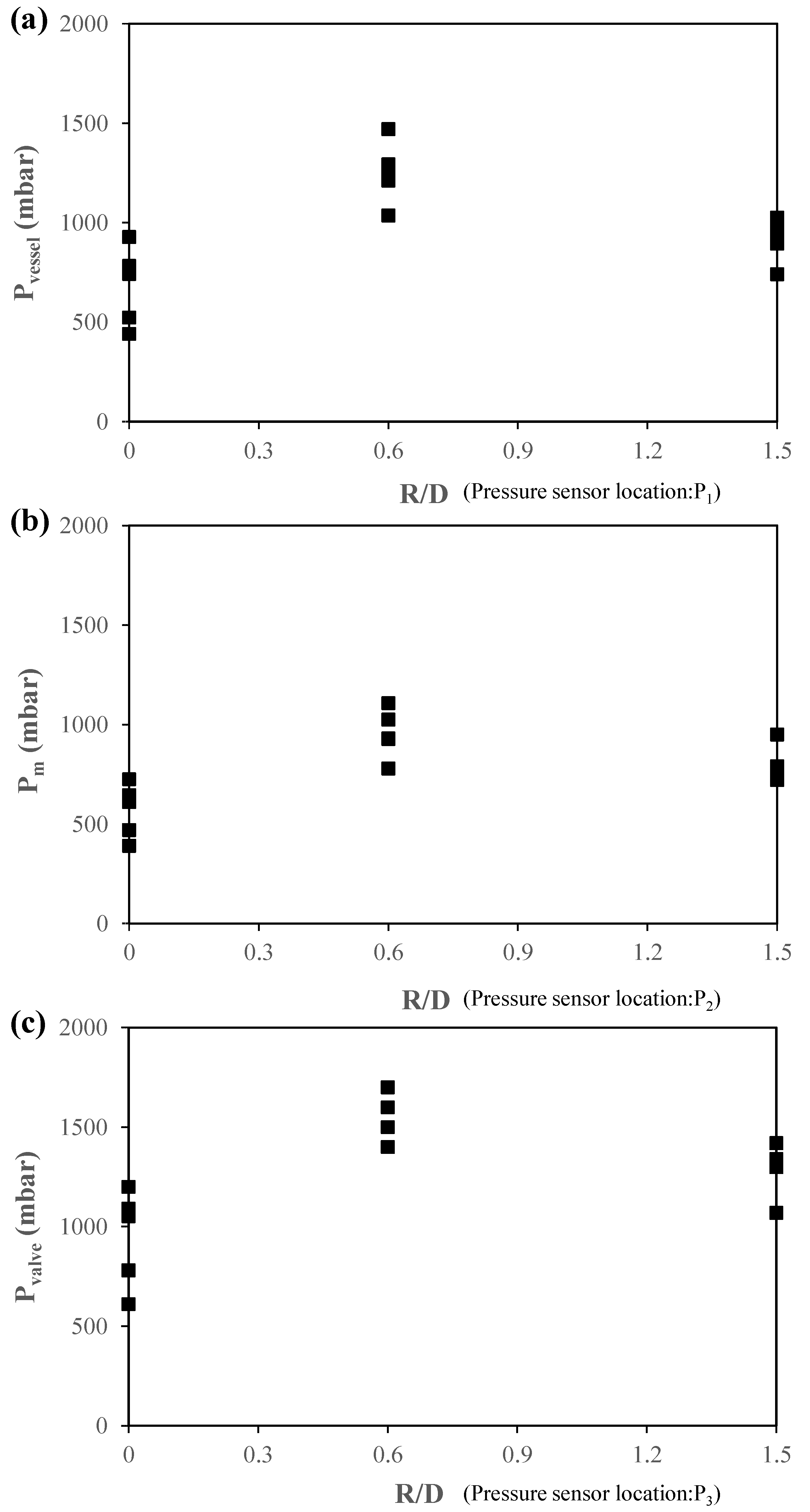
In Figure 6, pressure measurements obtained with straight and bent ducts are compared. Pressures were measured at three different locations: near to the vessel (P1); in the middle of duct, between the second and third bend (P2); and near to the valve after the third bend (P3) (Figure 3). For Al and MS dusts, the more obstacles there were, the higher the pressure was in the three locations reaching similar values. Regarding the increase in pressure due to the bends, this can be explained by the reflected shock wave. When a shock pressure wave hits a solid surface, a new shock wave appears, called a reflected wave, and moves in the opposite direction. According to Russell A. Ogle, reflected waves are important because they usually cause a greater overpressure than the original one [24,27].
Regarding the results of WF dust, it can be seen that the pressure fell when using bends. This can be explained by the slower burning rate, which might have meant that the pressure propagation wave was also weaker [28]. Thus, it can be concluded that the effect of bends on explosion dynamics depends on the reactive properties of the dust.
In addition, as expected for all tests (with and without bends), the pressure in the valve increased as the blast travelled along the duct (the pressure near the flap valve was about twice that in the vessel) [26].
Concerning the influence on the flap valve design and assessing its functionality, the potential rise in pressure due to the use of bends should be considered. In addition, some researchers consider that the residual pressure produced by the bends can affect the venting efficiency, thus it must be also considered in this regard [29].

3.3. Influence of Bends (R/D Ratio of 0.6) on the Explosion Wave Propagation

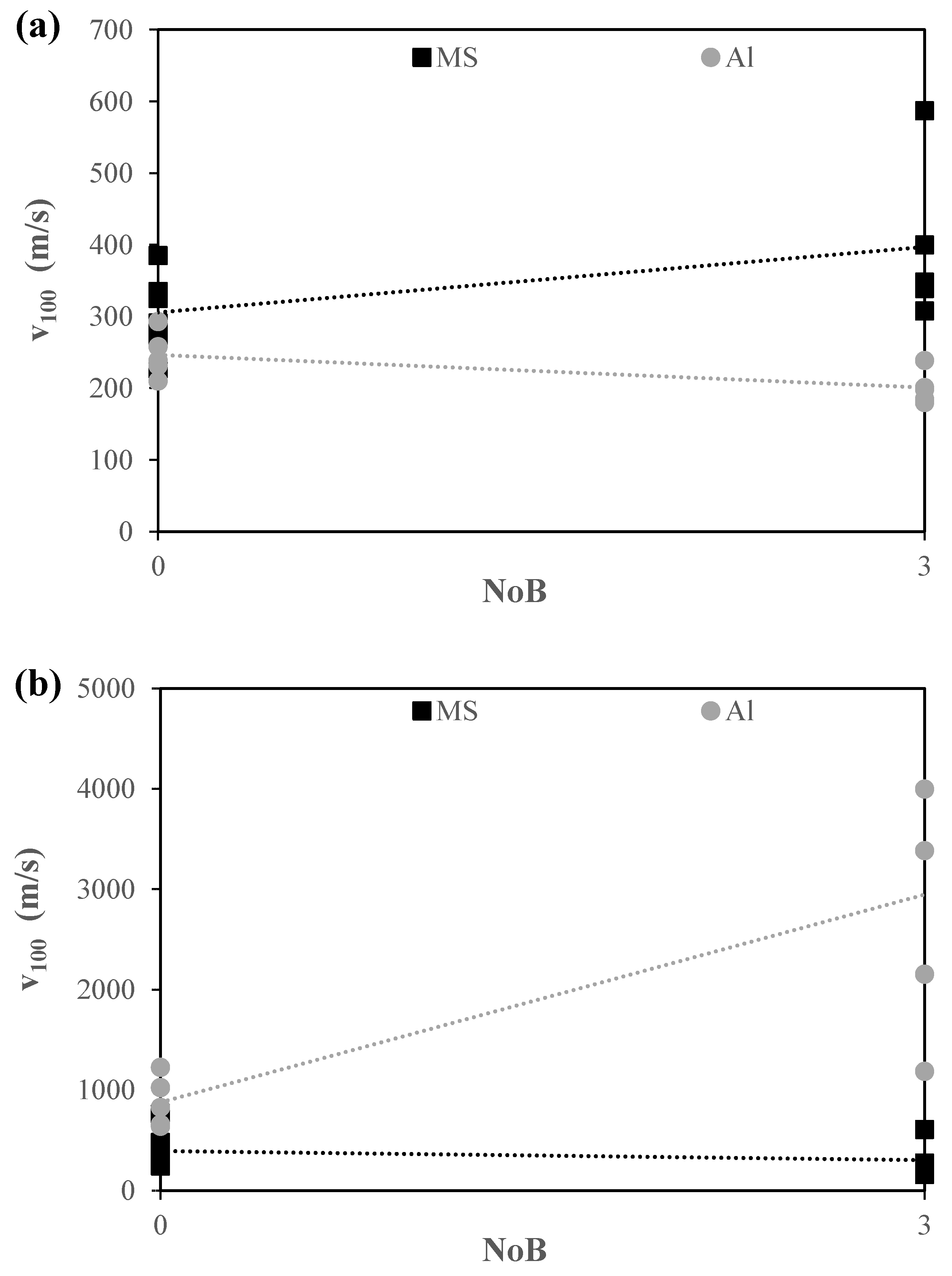
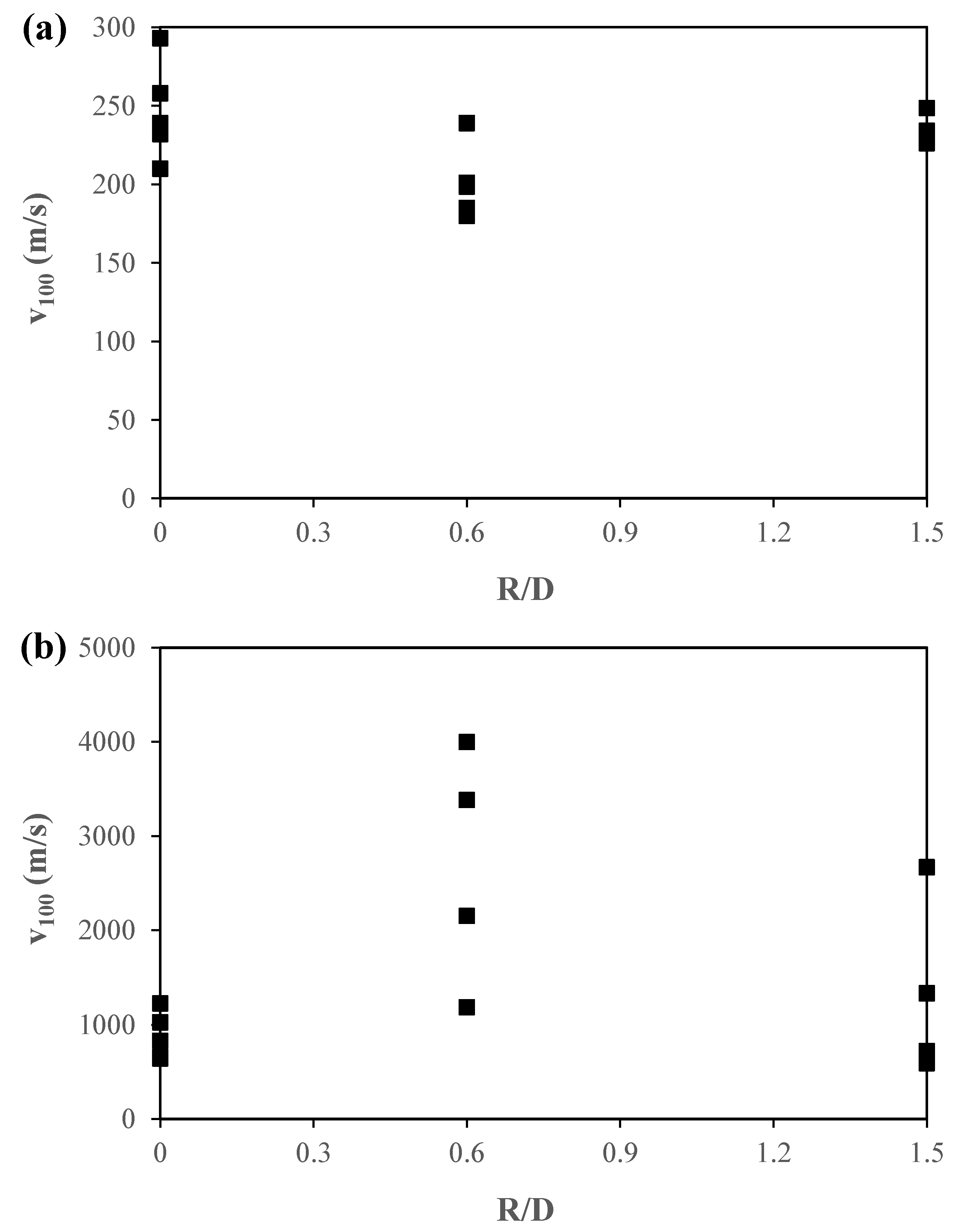
Once the effect of bends on flame velocity and pressure rise were evaluated, the explosion wave propagation at 100 mbar was analysed. At this point, Al and MS dusts were selected owing to their higher explosion severity. Figure 7a,b show the wave propagation speed for bent and straight ducts. This was determined between positions 1 and 2 and 2 and 3, respectively (Figure 3). For Al dust, similar results were obtained for bent and straight ducts in the earlier stage. Nevertheless, between position 2 and 3, the bends caused the flame propagation velocity to build up considerably. It can be concluded that the first two bends had less influence on flame acceleration than the third bend, for Al dust. However, the opposite trend was observed for MS dust, where the first two bends had more influence on flame acceleration which was related to a higher increase in pressure in the first part of the duct. These results were in keeping with those described in Section 3.1, where the flame from the aluminium explosion went further, and an increase in speed was observed due to the turbulence created by the higher-pressure wave. In short, wave propagation was accelerated along the duct for both configurations of ducts and dusts. This occurred as a result of that explained before in Section 3.2.

3.4. Influence of R/D Ratio on Flame Speed, Pressure and Wave Propagation

Finally, the effect of the R/D ratio on flame speed, pressure and wave propagation at 100 mbar was evaluated. For this analysis, aluminium was selected due to the more intense explosion produced. In Figure 8, the trend in pressure is shown using a straight duct, bends with a R/D ratio of 0.6, usually considered as short radius bends, and ones with a ratio of 1.5, typically considered as long radius bends.
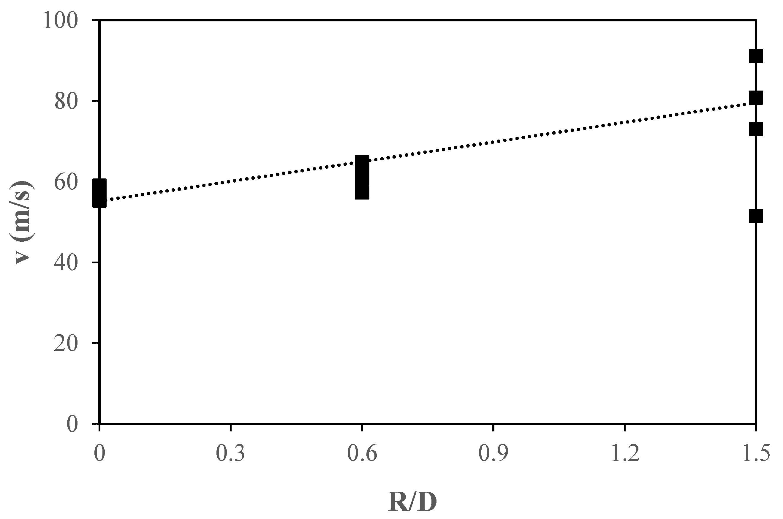
As in the case of bends with a R/D ratio of 0.6 (Section 3.2), the use of bends showed higher pressure in all locations where the sensors were: in the vessel, in the middle of the duct and in the valve. Moreover, as expected, the pressure in the valve was higher than that in the vessel. The highest results were obtained using bends with a R/D ratio of 1.5, more than those with a straight duct configuration. This can be explained in the same way as for a R/D ratio 0.6 (see Section 3.2). The bend contributed by reflecting the wave and the accumulate dust. This in turn enhanced combustion, and the more combustion gases there were, the more compressed they were. As a result, there was a rise in overpressure. Regarding flame speed (Figure 9), the same behaviour as commented in Section 3.1 was observed. The bends led to a significant increase in flame velocity (58 ± 2 and 82 ± 18 m/s for straight and bent ducts, respectively). These outcomes could be explained as in Section 3.1. The bends enhanced turbulence as well as the mass burning rate, which led to an increase in the flame speed. Concerning the propagation of the pressure wave shown in Figure 10, higher pressures were obtained in the second section of the duct. It can be concluded that the second part of the duct (between the third bend and the valve) had more influence on the pressure increase. Regarding the first section of the duct, pressures levels were similar when using straight and bent ducts (around 247 ± 28 m/s for the straight duct and 201 ± 21 m/s for the bent duct).
Then, the influence of the R/D ratio of the duct was evaluated. An R/D ratio of 0.6 showed a higher rise in pressure and blast wave propagation (Figure 8 and Figure 10) along the duct than a R/D ratio of 1.5. A short radius (R/D = 0.6) meant there was a sharper turn which may have led to a higher drop in pressure than with a long radius (R/D = 1.5). A shorter radius might imply a more intense reflection of the pressure wave. It should also be noted that the space for releasing the combustion gases would be lower. Therefore, this could cause a higher compression of the gases and the pressure signal. However, long radius bends obtained the highest flame velocity (81 ± 19 m/s) (Figure 9), which could be explained by its lower pressure drop. In addition, another observation was that the turbulence effect was more remarkable for long radius R/D bends.
Finally, as can be seen, both long and short radius bends showed remarkable effects on rises in pressure and flame speed. Thus, flap valves should be tested using all types of bends considering their intended use in industry.
In Table 4 deviations in pressures and flame velocities can be seen, as well as the environmental conditions for the different tests with the R/D ratio for the bends and different dusts tested.

4. Conclusions

Dust explosions were carried out using aluminium, maize starch and wheat flour on a large scale, using a 1 m3 vessel with a duct and a protective system mounted in it. The influence of bends on the propagation of the dust explosion and the functionality of flap valves were studied, from which the following conclusions were drawn:
  • Flame velocity is affected by the reactivity of the dust when bends are in the duct;
  • The rise of pressure experienced due to the use of bends should be considered when designing flap valves in order to provide enough resistance;
  • The R/D ratio of the bend has an influence on pressure and flame speed; pressures registered were higher for shorter radius bends than for longer ones, while for the flame speed, higher velocities were obtained when longer radius bends were used;
  • Data has been provided for the working group entrusted with reviewing standard EN 16447 for their consideration, which is used to test flap valves and evaluate the functionality of these protective systems.

Author Contributions

Conceptualization, I.G.-C. and Á.R.-G.; Methodology, I.G.-C. and Á.R.-G.; Validation, I.G.-C. and Á.R.-G.; Formal Analysis, I.G.-C. and Á.R.-G.; Investigation, I.G.-C. and Á.R.-G.; Resources, I.G.-C. and M.P.-G.; Data Curation, I.G.-C. and M.P.-G.; Writing—Original Draft Preparation, I.G.-C. and M.P.-G.; Writing—Review & Editing, I.G.-C. and Á.R.-G.; Visualization, I.G.-C., M.P.-G. and Á.R.-G.; Supervision, Á.R.-G.; Project Administration, I.G.-C. and Á.R.-G. All authors have read and agreed to the published version of the manuscript.

Funding

This research received no external funding.

Institutional Review Board Statement

Not applicable.

Conflicts of Interest

The authors declare no conflict of interest.

References

  1. ISSA. Dust Explosion Incidents: Their Causes, Effects and Prevention Examples 2, 3 and 10; International Social Security Association: Geneva, Switzerland, 2005; Volume 2051. [Google Scholar]
  2. Blair, A.S. Dust Explosion Incidents and Regulations in the United States. J. Loss. Prev. Process Ind. 2007, 20, 523–529. [Google Scholar] [CrossRef]
  3. Abbasi, T.; Abbasi, S.A. Dust Explosions–Cases, Causes, Consequences, and Control. J. Hazard. Mater. 2007, 140, 7–44. [Google Scholar] [CrossRef] [PubMed]
  4. Eckhoff, R.K. Current Status and Expected Future Trends in Dust Explosion Research. J. Loss. Prev. Process Ind. 2005, 18, 225–237. [Google Scholar] [CrossRef]
  5. Yuan, Z.; Khakzad, N.; Khan, F.; Amyotte, P. Dust Explosions: A Threat to the Process Industries. Process Saf. Environ. Prot. 2015, 98, 57–71. [Google Scholar] [CrossRef]
  6. Eckhoff, R.K. Dust Explosions in the Process Industries, 3rd ed.; Gulf Professional Publishing: Houston, TX, USA, 2003; ISBN 978-0-7506-7602-7. [Google Scholar]
  7. Kern, H.; Wieser, G.J.; Raupenstrauch, H.; Leoben, M. The Influence of Reduced Pressure on Flame Propagation in Dust/Air Mixtures. In Symposium Series No 159; IchemE: Rugby, UK, 2014. [Google Scholar]
  8. Eckhoff, R.K.; Li, G. Industrial Dust Explosions. A Brief Review. Appl. Sci. 2021, 11, 1669. [Google Scholar] [CrossRef]
  9. Skjold, T.; Castellanos, D.; Olsen, K.L.; Eckhoff, R.K. Experimental and Numerical Investigation of Constant Volume Dust and Gas Explosions in a 3.6-m Flame Acceleration Tube. J. Loss. Prev. Process Ind. 2014, 30, 164–176. [Google Scholar] [CrossRef]
  10. Tascón, A.; Ramírez-Gómez, Á.; Aguado, P.J. Dust Explosions in an Experimental Test Silo: Influence of Length/Diameter Ratio on Vent Area Sizes. Biosyst. Eng. 2016, 148, 18–33. [Google Scholar] [CrossRef]
  11. Amyotte, P. An Introduction to Dust Explosions. Understanding the Myths and Realities of Dust Explosions for a Safer Workplace; Butterworth-Heinemann: Oxford, UK, 2013; ISBN 978-0-12-397007-7. [Google Scholar]
  12. Rani, S.I.; Aziz, B.A.; Gimbun, J. Analysis of Dust Distribution in Silo during Axial Filling Using Computational Fluid Dynamics: Assessment on Dust Explosion Likelihood. Process Saf. Environ. Prot. 2015, 96, 14–21. [Google Scholar] [CrossRef] [Green Version]
  13. EN 16447-2014; Explosion Isolation Flap Valves. European Committee for Standardization: Brussels, Belgium, 2014.
  14. Pu, Y.K.; Mazurkiewicz, J.; Jarosinski, J.; William Kauffman, C. Comparative Study of the Influence of Obstacles on the Propagation of Dust and Gas Flames. Symp. (Int.) Combust. 1989, 22, 1789–1797. [Google Scholar] [CrossRef]
  15. Phylaktou, H.; Andrews, G.E. Gas Explosions in Linked Vessels. J. Loss. Prev. Process Ind. 1993, 6, 15–19. [Google Scholar] [CrossRef]
  16. Zhu, C.J.; Gao, Z.S.; Lin, B.Q.; Tan, Z.; Sun, Y.M.; Ye, Q.; Hong, Y.D.; Guo, C. Flame Acceleration in Pipes Containing Bends of Different Angles. J. Loss. Prev. Process Ind. 2016, 43, 273–279. [Google Scholar] [CrossRef]
  17. UNE-EN 14034-1:2005+A1:2011; Determination of Explosion Characteristics of Dust Clouds—Part 1: Determination of the Maximum Explosion Pressure Pmax of Dust Clouds. European Committee for Standardization: Brussels, Belgium, 2011.
  18. UNE-EN 14034-2:2006+A1:2011; Determination of Explosion Characteristics of Dust Clouds—Part 2: Determination of the Maximum Rate of Explosion Pressure Rise (Dp/Dt)Max of Dust Clouds. European Committee for Standardization: Brussels, Belgium, 2011.
  19. Barton, J.A. Dust Explosion Prevention and Protection: A Practical Guide, 2nd ed.; Gulf Professional Publishing: Woburn, MA, USA, 2002; ISBN 0-7506-7519-3. [Google Scholar]
  20. Institut Fûr Arbeitsschutz der Deutschen Gesetzlichen Unfallversicherung (IFA). Available online: https://staubex.ifa.dguv.de/ (accessed on 20 September 2022).
  21. Wang, Y.; Jiang, S.; Wu, Z.; Shao, H.; Wang, K.; Wang, L. Study on the Inhibition Influence on Gas Explosions by Metal Foam Based on Its Density and Coal Dust. J. Loss. Prev. Process Ind. 2018, 56, 451–457. [Google Scholar] [CrossRef]
  22. Lin, S.; Liu, Z.; Qian, J.; Li, X. Comparison on the Explosivity of Coal Dust and of Its Explosion Solid Residues to Assess the Severity of Re-Explosion. Fuel 2019, 251, 438–446. [Google Scholar] [CrossRef]
  23. Wang, S.; Pu, Y.; Fu, J.; Gutkowski, A. Effect of Turbulence on Flame Propagation in Cornstarch Dust-Air Mixtures. J. Therm. Sci. 2006, 15, 186–192. [Google Scholar] [CrossRef] [Green Version]
  24. Ogle, R.A. Dust Flame Acceleration Effects. Dust Explos. Dyn. 2017, 2017, 499–566. [Google Scholar] [CrossRef]
  25. Li, Q.; Yuan, C.; Tao, Q.; Zheng, Y.; Zhao, Y. Experimental Analysis on Post-Explosion Residues for Evaluating Coal Dust Explosion Severity and Flame Propagation Behaviors. Fuel 2018, 215, 417–428. [Google Scholar] [CrossRef]
  26. Yann Gregoire, E.L.C.P. Function Testing of Passive Explosion Isolation Flap. In Proceedings of the 9th International Seminar on Fire and Explosion Hazards (ISFEH 9), St. Petersburg, Russia, 21–26 April 2019; pp. 345–355. [Google Scholar]
  27. Mei, Y.; Shuai, J.; Zhou, N.; Ren, W.; Ren, F. Flame Propagation of Premixed Hydrogen-Air Explosions in Bend Pipes. J. Loss. Prev. Process Ind. 2022, 77, 104790. [Google Scholar] [CrossRef]
  28. Wang, C.; Zhao, Y.; Addai, E.K. Investigation on Propagation Mechanism of Large Scale Mine Gas Explosions. J. Loss. Prev. Process Ind. 2017, 49, 342–347. [Google Scholar] [CrossRef]
  29. Olugbemide, D.I. A CFD Study of the Effects of Pipe Bending Angle on Pressure Piling in Coal Dust Explosions in Interconnected Vessels. Fire Saf. J. 2022, 128, 103540. [Google Scholar] [CrossRef]
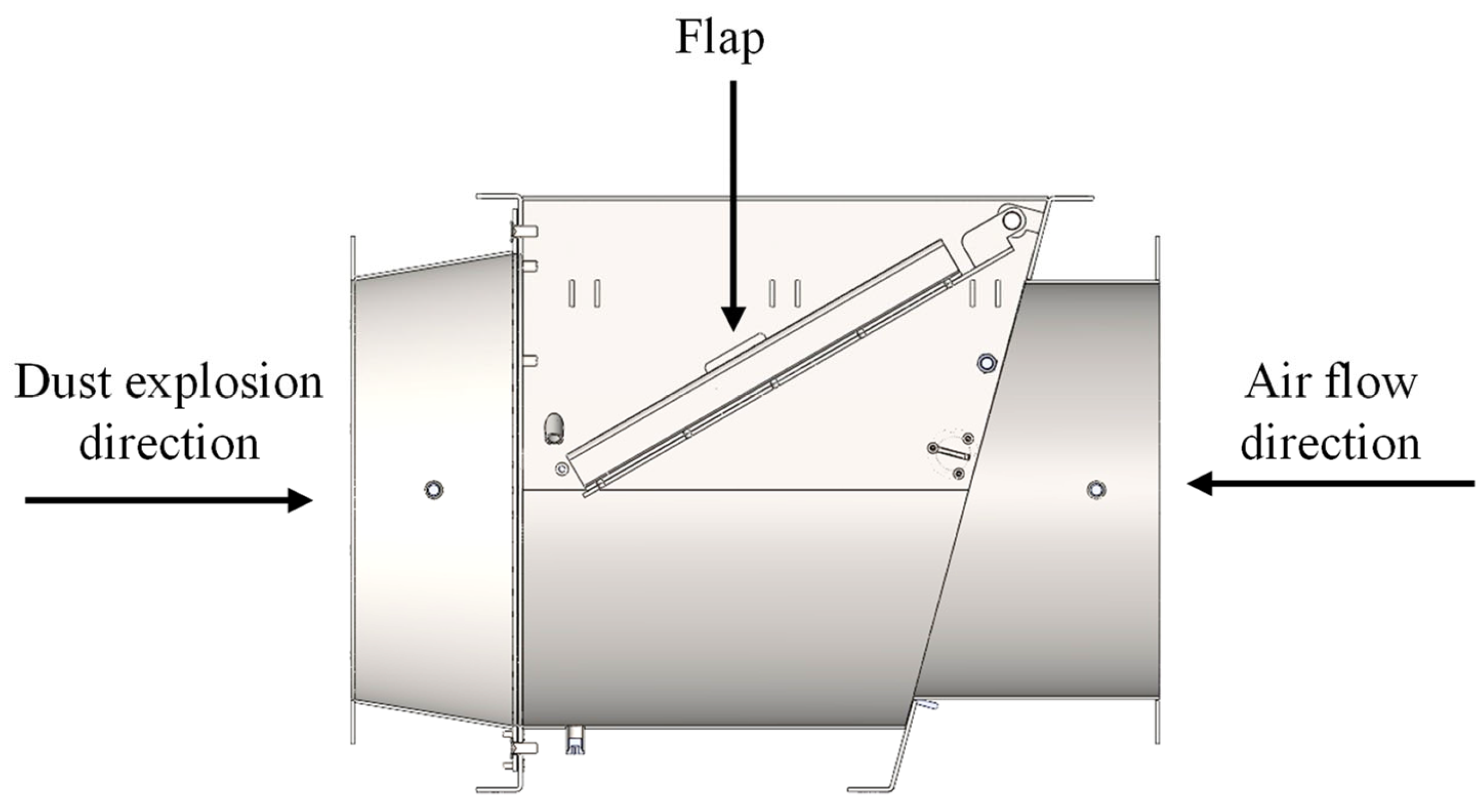
Figure 1. Flap valve diagram.
Applsci 12 11654 g001
Figure 2. Test setup for a DN500 flap valve mounted at a distance of 10.2 m measured from the 1 m3 vessel, in a duct with three short radius bends (R/D = 0.6).
Applsci 12 11654 g002
Figure 3. Technical drawing of duct configurations used: (a) straight duct, (b) including 90° bends.
Applsci 12 11654 g003
Figure 4. Influence of bends (R/D ratio 0.6) on flame speed between position 1 and 2 for each dust.
Applsci 12 11654 g004
Figure 5. Trend in flame speed along the duct for Al dust using bends (R/D ratio 0.6) calculated from position 1 to 2 and from 2 to 3.
Applsci 12 11654 g005
Figure 6. Influence of bends (R/D ratio of 0.6) on pressure for each dust: (a) pressure in the vessel (P1), (b) pressure in the middle of the duct (P2), (c) pressure near the valve (P3).
Applsci 12 11654 g006
Figure 7. Influence of bends on the propagation of pressure waves for Al and MS along ducts: (a) Wave propagation speed between position 1 and 2, (b) Wave propagation speed between position 2 and 3.
Applsci 12 11654 g007
Figure 8. Influence of R/D ratio on pressure for aluminium dust explosions: (a) Vessel pressure (P1), (b) pressure in the middle of duct (P2), (c) valve pressure (P3).
Applsci 12 11654 g008
Figure 9. Influence of R/D ratio on flame speed between position 1 and 2 for aluminium dust explosions.
Applsci 12 11654 g009
Figure 10. Influence of R/D ratio on pressure wave propagation for aluminium explosions along ducts: (a) Wave propagation speed between position 1 and 2, (b) Wave propagation speed between position 2 and 3.
Applsci 12 11654 g010
Table 1. Dust characterisation.
Raw MaterialConcentration (g/m3) *Kst (bar·m/s)Pmax (bar)
Al10003049.9
MS500 (1)135 (2)9.5 (3)
WF500937.6
* Optimum dust concentration which provides the maximum value of Kst; (1) (2) Kst of MS has been calculated in a vessel of 1 m3 at 25 °C. (3) Pmax of MS has been obtained from IFA [20].
Table 2. Summary of the tests performed for the straight duct.
Injection Location (m)Pressure Sensor Location (m)Flame Sensor Location (m)
TestDust TypeDuct Length (m)N° of BendsVessel Volume (m3)VesselI1I2P1P2P3F1F2F3
Al-0-1Al13 + V + 3.4701z13.567.260.17.2612.90.16.1312.9
Al-0-2
Al-0-3
MS-0-1MS13 + V + 3.4701z13.567.260.17.2612.90.16.1312.9
MS-0-2
MS-0-3
WF-0-1WF13 + V + 3.4701z13.567.260.17.2612.90.16.1312.9
WF-0-2
WF-0-3
V: valve position; Ix: additional injection bottles; Px: pressure detector; Fx: flame detector; Z1: Position of the ignitor (in the middle of vessel) according to EN 16447 [13].
Table 3. Summary of the tests performed for the curved duct with a R/D ratio of 0.6 and 1.5.
Injection Location (m)Pressure Sensor Location (m)Flame Sensor Location (m)
TestDust TypeDuct Length (m)N° of BendsVessel Volume (m3)Vessel I1 I2P1P2P3F1F2F3
Al-3-1Al1.1 + B + 1.93 + B+
+2.47 + B + 3 + V + 3.47
31z11.1 + B + 0.961.1 + B + 1.93 + B + 1.230.11.1 + B + 1.93 + B + 1.231.1 + B + 1.93 + B + 2.47 + B + 2.90.11.1 + B + 1.93 + B + 0.11.1 + B + 1.93 + B + 2.47 + B + 2.9
Al-3-2
Al-3-3
MS-3-1MS1.1 + B + 1.93 + B+
+2.47 + B + 3 + V + 3.47
31z11.1 + B + 0.961.1 + B + 1.93 + B + 1.230.11.1 + B + 1.93 + B + 1.231.1 + B + 1.93 + B + 2.47 + B + 2.90.11.1 + B + 1.93 + B + 0.11.1 + B + 1.93 + B + 2.47 + B + 2.9
MS-3-2
MS-3-3
WF-3-1WF1.1 + B + 1.93 + B+
+2.47 + B+3 + V + 3.47
31z11.1 + B + 0.961.1 + B + 1.93 + B + 1.230.11.1 + B + 1.93 + B + 1.231.1 + B + 1.93 + B + 2.47 + B + 2.90.11.1 + B + 1.93 + B + 0.11.1 + B + 1.93 + B + 2.47 + B + 2.9
WF-3-2
WF-3-3
V: valve position; Ix: additional injection bottles; Px: pressure detector; Fx: flame detector; Z1: Position of the ignitor (in the middle of vessel) according to EN 16447 [13]; B: bend position.
Table 4. Summary of pressures and velocities obtained during the tests and environmental conditions.
CombustibleR/D RatioT (°C)H (%)P1 (mbar)P2 (mbar)P3 (mbar)V1–2 (m/s)V2–3 (m/s)
AL023 ± 444 ± 8684 ± 178569 ± 122947 ± 21858 ± 2
0.625 ± 338 ± 71253 ± 141955 ± 1111540 ± 10262 ± 380 ± 7
1.522 ± 456 ± 12913 ± 97799 ± 811288 ± 11781 ± 19
MS024 ± 251 ± 25233 ± 65250 ± 74347 ± 9629 ± 9
0.625 ± 441 ± 191217 ± 2181302 ± 2591608 ± 33837 ± 6
WF014 ± 660 ± 21134 ± 36140 ± 8185 ± 1820 ± 6
0.620 ± 454 ± 10143 ± 33171 ± 39202 ± 388 ± 2
T: average ambient temperature; H: average ambient moisture; Px: average pressure for each sensor; V1–2: average flame velocity between positions 1 and 2; V2–3: average flame velocity between positions 2 and 3.
Publisher’s Note: MDPI stays neutral with regard to jurisdictional claims in published maps and institutional affiliations.