Abstract
This paper comparatively analyzes the static random-access memory (SRAM) cell designs for fault tolerance. Since SRAM cells are sensitive to radiation-induced single event upsets, various circuit-level approaches have been applied. Compared to the conventional SRAM cell circuits, one possibility is adding redundant storage nodes by means of additional transistors. The strength and weakness of the SRAM cells in terms of various performance aspects—speed, area, power, stability, fault tolerance, etc.—according to the design approaches are compared analytically and discussed. The discussion concludes that, in the future, it is paramount to develop an SRAM cell design with a mitigated trade-off between read/write performance and SEU tolerance.
1. Introduction
As technology scales down, there have been significant developments in current drivability and a substantial reduction in the parasitic capacitances of transistors. This leads to improvements in the speed, power consumption, and area of digital circuits. On the other hand, because the amount of charge representing a logic value for a digital circuit is significantly reduced, the voltage of nodes in circuits can be more easily changed. In other words, the signals in the digital circuits have become highly sensitive to external noise sources. Specifically, the radiation-induced energetic ionized particles in the atmosphere usually contain charge sufficient to flip the data of the memory in the digital circuit. Thus, it is more likely to result in a logical error for the circuit operation.
The most vulnerable digital circuit component to such a fault is the static random-access memory (SRAM) cell, which is a hardware component that stores data in logical values. In the conventional 6 T SRAM cell, the simple cross-coupled inverter configuration means that the stored data can be easily flipped by the radiation-induced charge particle. To enhance the fault tolerance, various device-level, layout-level, circuit-level, or system-level design techniques are developed. Among these various approaches, the most promising one is to revise the topology of the SRAM cell at the circuit level to make its storage nodes less sensitive to external charge shocks, while keeping its initial stored voltage.
There have been numerous radiation-hardened SRAM designs proposed. In order to make the SRAM cell robust to the radiation-induced charge noise, it is typical to employ extra transistors in a more complex manner compared to 6 T SRAM. This inevitably incurs overhead in terms of the area, power, speed, and operation stability. It is valuable to conduct a comparative analysis on the various SRAM cell designs in terms of various performance aspects.
The rest of this paper is organized as follows. In Section 2, the background for the error observed in the circuit components due to radiation-induced noise and different design approaches for radiation hardening design are considered. In Section 3, the various SRAM cell designs are introduced in detail. In Section 4, the SRAM cell designs introduced in Section 3 are compared and discussed in various respects.
2. Background
2.1. Soft Error and Single Event Transient (SET)
Due to the defects during the fabrication process or circuit design error, there may occur permanent physical flaws in the hardware, leading to a fault or error in the electronic device’s operation. This is a so-called “hard error” of the electronic device. Even in hardware free from this hard error, it has been observed that the data bits are spontaneously or dynamically changed to incorrect values, through various noise sources affecting the electronic device after fabrication. This failure is not repeatable, non-destructive, and non-permanent, which is referred to as a “soft error” to differentiate it from the hard error.
There are two types of soft error: intermittent faults and transient faults [1]. Intermittent faults occur from time to time in irregular intervals, usually at the same locations. The causes of intermittent faults are power supply noise, temperature changes, aging of circuit components, and signal coupling of parasitic capacitances. The intermittent fault has become less critical in the advanced technology because it can be minimized through recent well-developed design and manufacturing techniques. However, the transient errors, which are caused mainly by cosmic rays and alpha particles, occur randomly and are much more unpredictable and unavoidable. Alpha particles or high-energy neutrons in the atmosphere can accidentally impact the transistors in the electronic device, which leads to the generation of charges. Then, the voltage of the nodes in the circuit can be changed to the incorrect state, so a logic error can occur.
In integrated circuits, the diffusion nodes (drain or source) of the “off” transistors are sensitive to the voltage change due to the particle impact. The voltage change occurs in the following procedure. If an energetic particle hits a source or drain node and passes through the transistor, electron–hole pairs are generated near the p–n junction of the source or drain diffusion. Along the path of particle injection, the depletion region of the p–n junction is extended, which leads to the generation of a high electric field. Thus, the generated carriers (i.e., electron–hole pairs) are collected by the electric field, which creates a temporal junction current. This current results in a sudden voltage change at the source or drain node. For example, in off nMOSFET, the source or drain is n+-doped and the electrons are collected towards the n+ side, and the node voltage is substantially lowered. This phenomenon is called single event transient (SET). For a pMOSFET whose drain or source is p+-doped, the node voltage can be unintentionally raised due to SET.
2.2. Single Event Upset (SEU) and Radiation-Hardening Design Techniques
In the memory of the digital circuit, SET can change the digital value at the storage nodes, leading to data flipping (0 → 1 or 1 → 0). This logical value change by SET is referred to as single event upset (SEU). In the conventional 6 T SRAM cell shown in Figure 1, the storage nodes Q and QB are not only the drains of access transistors (MX1,2) and pull-down transistors (MD1,2), which are nMOSFETs, but also are the drains of pull-up transistors (MU1,2), which are pMOSFETs. Thus, the Q and QB nodes are exposed to both polarities of SET, 0 → 1 and 1 → 0. For example, when Q = VDD and QB = 0 V, which means that the value of “1” is stored, an amount of charge can be collected to result in 1 → 0 SET at Q node. This makes the QB node change from 0 V to VDD accordingly, so the memory cell state is changed into the value of “0”, which means that the data are flipped erroneously. To enhance the robustness to SEU, there have been several radiation-hardening design techniques.
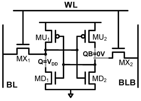
Figure 1.
Schematic of the conventional 6 T SRAM cell.
First, layout-level techniques can be applied as in [2,3,4], such as shallow trench isolation, H-gate, and enclosed annular gate. Through shallow trench isolation, the charge injection node can be isolated from the charge collection node to reduce the possibility of SEU. Through the layout based on the H-gate or annular gate, the leakage current can be efficiently suppressed due to the unique shape of the gate. However, in the present sub-nanotechnology era, these techniques are unlikely to be applicable due to the highly constrained design rules.
The triple modular redundancy (TMR) is one of the most widely used classical circuit-level radiation-hardened design techniques [5]. In TMR, three copies of memory cells are implemented to hold the identical data during the operation. For read accessing data, a majority voting circuit is employed to decide the final output as the majority data. In this manner, even if one cell stores incorrect data due to SEU, the other two copies keep the correct data, which are unchanged from the initial values. The voting process guarantees that the output data are correct. However, due to the requirement for implementing and operating three copies of hardware, there is a significant amount of area and power overhead.
At the system level, the most well-known radiation-hardening design technique is the error correction code (ECC) [6,7,8,9,10,11]. By writing the multi-bit word data after encoding them to follow a specific pre-determined policy, one or multi-bit error can be detected or corrected by decoding the data at the read-accessing phase. In other words, once some bits of the word are flipped by SEU, the bit sequencing of the word does not follow the pre-determined rule. By analyzing how the word violates the rule, the error bit can be found and corrected. However, applying ECC requires complex encoding and decoding circuits, which incurs a significantly large timing and power overhead.
One of the most promising approaches to enhance the robustness for SEU, and thus the most widely used method, is to design a new hardened SRAM cell, instead of relying on the conventional 6 T SRAM cell. With this approach, most of the peripheral circuits and systems, and the architecture, are kept unchanged; only the memory cell is replaced with the new radiation-hardened SRAM cell design. Compared to the other approaches, utilizing the new memory cell design is efficient in terms of its practicality and performance. In the following section, various SRAM cell designs for radiation hardening are described in terms of their structure, operation, and key performance characteristics.
3. Radiation-Hardened SRAM Cell Design
3.1. Dual Interlocked Storage Cell (DICE)
Figure 2 shows a schematic of 12 T DICE [12], which is one of the most popular radiation-hardened SRAM cells. Unlike the conventional 6 T SRAM cell, there are four nodes to store the data,—A, B, C, and D—where A and C are to have the same logic level, while B and D have the same level for the given data. For example, when the cell stores data as “1” with a supply voltage of VDD, A = C = VDD and B = D = 0 V. For the read or write operation, the four access transistors N1-N4 are turned on by WL = VDD to connect the storage nodes to bit-line pairs BL and BLB, while WL is kept as 0 for the hold operation. The read and write operations are performed in a similar manner to the conventional 6 T SRAM cell. For the read operation, the stored data are submitted to BL and BLB. For the write operation, BL and BLB are first driven by the external write driver; then, the data are submitted to the storage node through the access transistors.
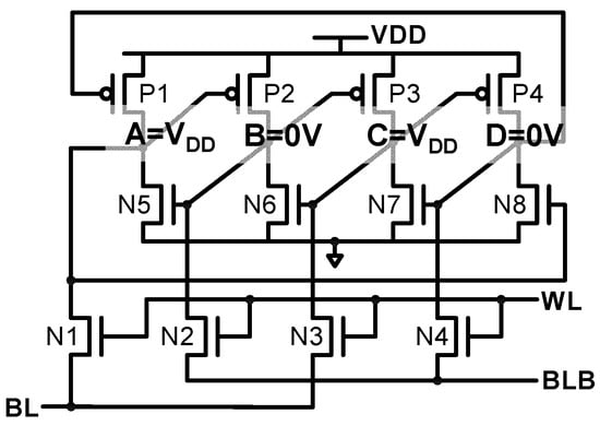
Figure 2.
Schematic of 12 T DIEC SRAM cell.
The key structural feature of DICE is that each storage node is driven by one pFET and one nFET, which are separately controlled by two different neighboring storage nodes. For example, A is driven by pFET P1 and nFET N5, whose gates are connected to D and B, respectively. This unique configuration means that the cell is immune to any error caused by a single node upset.
The SEU recovery behavior of DICE is as follows. For example, when the datum “1” is stored, A = C = VDD and B = D = 0 V. In this condition, the upset can occur on A, changing the voltage from VDD to 0. This turns P2 on, which starts to raise B. However, because C is still VDD, N6 is kept on, which limits the pull-up of B. Moreover, because D is still 0 V, P1 is kept on. Thus, A is recovered to VDD, and B stops being pulled up by P2. This means that the stored data are not flipped but remain as “1”, even though there is an event that erroneously pulls down the node A.
Nearly a 2-2.5-times greater overhead in terms of area and power consumption is inevitable. In addition, if multiple nodes are upset simultaneously, the data flip cannot be prevented in DICE.
3.2. Qud-Node 10 T or Quatro-10 T Cell and Write-Enhanced Quatro-12 T Cell (WE-Quatro-12 T)
Figure 3a shows a schematic of the Quatro-10 T cell proposed in [13]. Similar to DICE, four nodes inside the cell—A, B, C, and D—are used to store data. For example, when the datum “1” is stored, A = D = 0 V and B = C = VDD. Unlike DICE, only two nodes, A and B, are directly connected to differential bit-lines through two access transistors, N5 and N6, while C and D are not. Thus, the read operation is performed through turned-on access transistors with WL = VDD, which develop differential bit-lines according to the voltages of A and B. For the write operation, the bit-line voltages are first reflected to the nodes A and B; then, the nodes A and B are amplified through the inner positive feedback configuration composed of P1-N1-P3-N3. Then, the amplified A and B are fed back to fully develop the nodes C and D through the positive feedback configuration P2-N2-P4-N4.
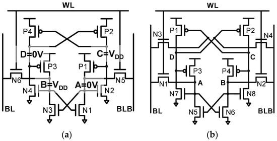
Figure 3.
Schematic of (a) Quatro-10 T and (b) WE-Quatro-12 T SRAM cell.
As in DICE, each of the four nodes in Quatro-10 T is also driven by one nFET and one pFET, where their gates are pinned to different nodes. In this manner, resilience to single node upset can be achieved. For example, when the data are stored as “1,” the node B is supposed to be VDD, with A = 0 V, C = VDD, and D = 0 V. In this situation, B can be accidently pulled down due to the upset and becomes 0 V, leading to N1 and N4 being turned off. However, no other node voltages are changed due to the turning off of these transistors. Instead, because D is kept at 0 V, P3 supplies the current to the lowered B. Thus, B is raised back to high, which means that the data “1” state is recovered.
However, Quatro-10 T is not tolerant for 0 to 1 SEU; it is only tolerant for 1 to 0 SEU. For example, when the datum “1” is stored, B should be kept as 0 V. In this condition, B can experience SEU of 0 V to VDD (i.e., 0 to 1). This turns on N1 and N4, which pulls down the nodes A and D, respectively. The lowered node D can cause C to rise through P2, which turns off P1. The turned-off P1 and turned-on N1 are combined to accelerate the lowering of the node A. Consequently, there is no option for the cell to recover to the initial state, which means that the data flip occurs.
In addition, the write ability of Quatro-10 T is very weak at a low voltage. For example, when the datum “0” is written to datum “1” in the hold cell, BL = VDD and BLB = 0 V should be well reflected to the nodes A and B, which initially store 0 V and VDD, respectively. However, the node A is weakly pulled up through N5 due to the Vth drop; thus, N2 is only weakly turned on and the node C is not well pulled down to raise the node D. This means that P3 remains turned on, which prevents the node B from being sufficiently pulled down by N6. Therefore, the write ability is significantly limited in the Quatro-10 T cell.
To mitigate the write ability problem of the Quatro-10 T cell, two transistors are additionally used and a write-enhanced Quatro-12 T cell (WE-Quantro-12 T) is proposed [13], as shown in Figure 3b. Through the two newly added access transistors, N7 and N8, the nodes C and D can also be connected to bit-line pairs. Thus, for the previously mentioned data “0” write case, the node D can be easily pulled up to turn off P3. This significantly enhances the write ability. However, as in Quatro-10 T, WE-Quatro-12 T does not have error tolerance for the 0 to 1 flip of the nodes A and B.
3.3. PMOS-Stacked 10 T SRAM Cell (PS-10 T), NMOS-Stacked 10 T SRAM Cell (NS-10 T), and Radiation-Hardened SRAM Cell (RHD-12 T)
Figure 4a,b show the PMOS-stacked 10 T SRAM cell and NMOS-stacked 10 T SRAM cell for radiation-hardened operation [14]. PS-10 T has a similar structure to Quatro-10 T; the only difference from Quatro-10 T is that the sources of MP3 and MP1 are not VDD but are connected to the nodes D and C, respectively. Due to this similarity, the read and write operations are also almost same as in Quatro-10 T.

Figure 4.
Schematic of (a) PS-10 T, (b) NS-10 T, and (c) RHD-12 T SRAM cell.
Similar to Quatro-10 T, PS-10 T and NS-10 T have only partial SEU robustness. In PS-10 T, 0 to 1 SEU cannot be recovered, while 1 to 0 SEU cannot be recovered in NS-10 T. For example, when NS-10 T stores datum “1”, which means that the nodes’ voltages are similar to A = VDD, B = 0 V, C = VDD, and D = 0 V, the node A can be accidently lowered by SEU. This results in the turning on of MP1 and MP4, leading to a rise in the nodes B and D. Thus, the pull-down path of A—MN1 and MN2—is enabled to statically drive A to 0 V, which means that the data are flipped.
Figure 4c shows the radiation-hardened design of the 12 T SRAM cell (RHD-12 T) proposed in [3], which has a similar structure to PS-10 T. The difference in RHD-12 T from PS-10 T is that the sources P3 and P4 are not driven by S1 and S0, respectively. Instead, P2 and P5, whose gates are S0 and S1, are newly added to drive P3 and P4, respectively. The shallow trench isolation is inserted in the P2-P3 stack or P5-P4 stack. In this manner, the drain nodes of P2 and P5, where charges can be collected by SEU, can be isolated from the source nodes of P3 and P4, where the collected charge could have been injected to cause a node flip. However, as with PS-10 T, RHD-12 T also cannot be recovered from the SEU induced to “0” storing the Q or QN nodes.
3.4. Radiation-Hardened-by-Design 10 T and 14 T SRAM Cell (RHBD-10 T and RHBD-14 T)
In Quatro-10 T, PS-10 T, or NS-10 T, only 1 to 0 or 0 to 1 is tolerable. However, the radiation-hardened-by-design 10 T SRAM cell (RHBD-10 T) [15], whose structure is shown in Figure 5a, is robust for both 1 to 0 and 0 to 1 SEU. Compared to Quatro-10 T, the two nFETs for driving the C and D nodes—N2 and N4 in Figure 2—are replaced by pFETs of P5 and P6. This change means that RHBD-10 T is tolerant for both 0 to 1 and 1 to 0 SEU.
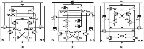
Figure 5.
Schematic of (a) RHBD-10 T, (b) RHBD-14 T, and (c) RHPD-12 T SRAM cell.
For example, when the datum “1” is stored for RHBD-10 T, Q = S1 = VDD, and QN = S0 = 0 V. In this situation, 0 to 1 upset can occur for the QN of RHBD-10 T. This turns on N2, which lowers Q temporarily. However, P4 is kept on, which pulls Q back up to VDD, leading to QN being lowered back to 0 V. This means that 0 to 1 upset to Q or QN can be recovered.
The 1 to 0 upset can also occur at the Q or QN node. For example, when the datum “1” is stored, Q, which is initially VDD, can be lowered due to 1 to 0 SEU. Then, P6 is unintentionally turned on to lower S1. However, the lowering of S1 is limited for two reasons: P1, which is sized larger than P6, is turned on to keep S1 high, and P6, which is pFET, can only deliver a weak “0” to S1. Hence, S1 will remain high and P2 stays off. Thus, the voltage of S0 is unchanged as 0 V to keep P4 turned on. Finally, the turned-on P4 flips Q back to its initial voltage, VDD, which means that 1 to 0 SEU can be recovered.
For the S0 and S1 nodes, 1 to 0 SEU cannot occur because there are no nFET diffusions (i.e., drains or sources) connected to the S0 and S1 nodes, but there are only pFET diffusions. Thus, the S0 or S1 nodes only suffer from 0 to 1, which does not turn on any transistors. Consequently, although S0 or S1 is unintentionally raised from 0 to 1 by SEU, it is lowered back by turning on P6 or P5, respectively.
Even with this good tolerance for all types of single node upset, the critical problem of RHBD-10 T is the weak write ability. For example, when datum “0” is supposed to be written for the datum “1” stored cell, Q should be lowered to 0 V by N4, which transfers BL = 0 V. To guarantee the lowering of Q, P4 should be turned off by raising S0, while the raising of S0 should be performed by turning on P2. However, turning on P2 requires the lowering of S1, which is highly challenging for RHBD-10 T. This is because S1 should be pulled down by pFET P6, not by nFET. Thus, the write failure probability of RHBD-10 T is greatly increased in low-voltage or high-frequency applications.
To mitigate the write failure problem of RHBD-10 T, RHBD-14 T is proposed in [16], which is shown in Figure 5b. The most pronounced change is that N3 and N4 are added to enhance the write ability. This approach is similar to the way in which WE-Quatro-12 T resolves the write ability problem of Quatro-10 T. When the node A should be pulled down, P5 and P7 are more easily turned off by the raised D because the node C is directly pulled down by N3. In addition, RHBD-14 T also employs the stacked configuration of pFETs to drive the nodes A or B—P5–P7 or P6–P8, respectively—to enhance the error resilience through the charge-sharing effect [16].
However, unlike RHBD-10 T, which has complete tolerance for SEU, the nodes C and D of RHBD-14 T are not tolerant for 1 to 0 SEU. For example, when the datum “1” is stored, A = C = VDD, and B = D = 0 V, and the node C can be lowered by SEU, leading to the raising of D by the turned-on P3. The node B is also raised by the turned-on P6 and P8, so the node A is lowered by N4. Hence, P1 is turned on, driving the node C to be low. This results in the data flip from “1” to “0.”
Another approach can be applied to resolve the weak write ability problem of RHBD-10 T. Figure 5c shows the structure of the radiation-hardened polar design of the SRAM cell (RHPD-12 T) [17]. RHPD-12 T is the polarity-reversed version of RHBD-10 T, while two additional transistors—N7 and N8—are applied to enable direct access to the internal storage nodes. In this manner, the complete tolerance to SEU can be maintained while the write failure problem can be significantly resolved.
However, during the read operation in which S0 or S1 stores a weak “1,” the driving strengths of N3 and N4 are weakened. As a result, the read stability margin is significantly reduced, which means that the data flip probability during the read operation becomes impractically high in the low-voltage region.
3.5. Radiation-Hardened-by-Design 12 T SRAM Cell (RHBD-12 T)
Figure 6 shows a schematic of the radiation-hardened-by-design 12 T SRAM cell (RHBD-12 T) proposed in [18]. The key structural feature of RHBD-12 T is that no nFET diffusion nodes are connected to Q and QB by using pFET access transistors. Thus, 1 to 0 upset is not generated at the Q or QB nodes, and only 0 to 1 upset occurs, which is recoverable. For example, when the datum “1” is stored by Q = S1 = VDD and QB = S0 = 0 V, as shown in Figure 6, QB can be temporarily raised by SEU, which turns on N4. However, P8 is in the off state; thus, no other storage nodes are affected. The raised QB is pulled down back to its original state by the P7-N2 path.
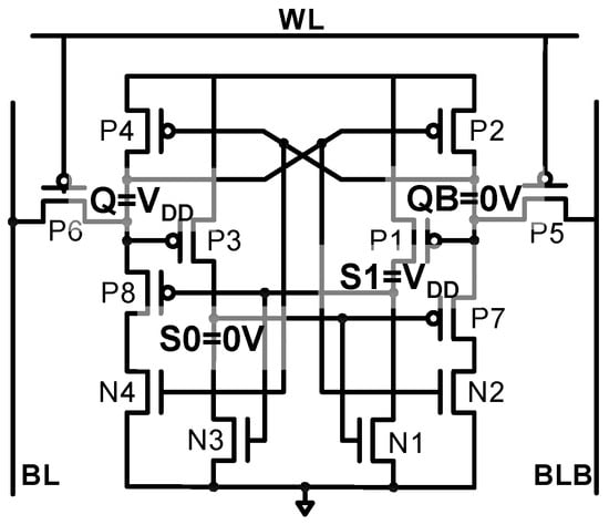
Figure 6.
Schematic of RHBD-12 T SRAM cell.
Unlike Q or QB, the S0 or S1 node can suffer from both 0 to 1 and 1 to 0 node upsets. However, these upsets can be recovered as follows. First, if 1 to 0 upset occurs at the node S1 for the data “1” state, P8 is turned on, while N3 is turned off. Although P8 is turned on, Q is not pulled down because N4 is still off. Thus, QB is kept low and P1 stays turned on, and S1 is recovered to VDD. Second, if 0 to 1 upset occurs at the node S0 for the data “1” state, N1 is temporarily turned on to pull down the node S1, which turns on P8. Again, however, N4 remains off, the high Q is unchanged, and QB can remain low. Thus, the node S1 is pulled back up to VDD, leading to the pulling down of S0 back to its original value 0 V.
The shortcoming of RHBD-12 T is the large read access time due to the use of the pFET access transistor and pull-down transistor. For reading data “1”, the pre-charged BLB is discharged by the cell current flowing through P5-P7-N2. However, unlike other memory cell structures, the magnitude of VGS in access transistor P5 and pull-down transistor P7 is decreased as BLB is discharged, which severely slows down the read operation. In addition, the use of pFET transistors significantly degrades the write speed and stability.
3.6. Quadruple Cross-Coupled Latch-Based 10 T and 12 T SRAM Cell (QUCCE-10 T and QUCCE-12 T)
Figure 7a,b show the schematics of the quadruple cross-coupled latch-based 10 T and 12 T SRAM cell (QUCCE-10 T and QUCCE-12 T), respectively [19]. Similar to the other previous SRAM cell structures, the four nodes A, B, Q, and QN are used to store the data, while each node is driven by pFET and nFET, whose gate nodes are connected to the different nodes. Specifically, the four cross-couple FETs form a full positive feedback network to store data.
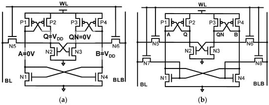
Figure 7.
Schematic of (a) QUCCE-10 T and (b) QUCCE-12 T SRAM cell.
However, the full positive feedback of QUCCE-10 T considerably lowers the SEU tolerance compared to the other radiation-hardened SRAM cell designs. An SEU-induced voltage change at any storage node can trigger the positive feedback, which in turn makes the initial voltage change severe. For example, for the data “1” stored cell—A = 0 V, B = VDD, Q = VDD, and QN = 0 V—0 to 1 SEU can occur on the QN node, leading to the pull-down of the Q node. This turns on P1 to raise the node A, so N4 is turned on, leading to the pull-down of B. As a result, P3 is turned on, making the voltage rise of QN more severe.
In addition, QUCCE-10 T suffers from a large write delay or reduced write stability in low-voltage regions. For example, when “0” is written to the “1” stored cell, Q = VDD is supposed to be pulled down by the turned-on N5. For a successful write, WL should be kept high until Q is lowered, A is raised, and then B is lowered so that QN becomes VDD to ensure that N2 is fully turned on. This necessitates a large pulse width for WL assertion, which results in an excessive write delay. To resolve this problem, QUCCE-12 T, shown in Figure 7b is also proposed, but the limited SEU tolerance issue still exists in QUCCE-12 T.
3.7. Radiation-Hardened-by-Design 11 T and 13 T SRAM Cell (RHBD-11 T and RHBD-13 T) and Radiation-Hardened Dynamic 11 T and 13 T SRAM Cell (RHD-11 T and RHD-13 T)
Figure 8a,b show the schematics of RHBD-11 T [12] and the 13 T SRAM cell [20], respectively. The key structural feature of these designs is that the nodes a1 and a2 are isolated and the refresh signals—rf and rfb—are employed. The roles of these refresh signals are to be explained later. There are four nodes to store the data; the nodes d, db, a1, and a2.
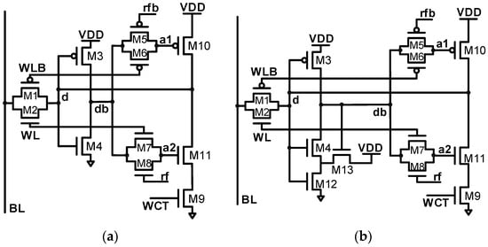
Figure 8.
Schematic of (a) RHBD-11 T and (b) RHBD-13 T SRAM cell.
For the write operation, the single-ended bit-line BL is driven first, and then WL and WLB become high and low, respectively, to connect the node d with BL. The refresh signals are only inserted for the refresh operation; thus, the nodes rf and rfb are low and high, respectively. For example, when the datum “0” is written, BL is low, so d is driven to be low as well. This makes db high and so the nodes a1 and a2 also become high due to the turned-on M6 and M7.
For the data hold, WL and WLB are disabled, so M6 and M7 are turned off. As a result, the nodes a1 and a2 are isolated and floated. To prevent the instability of the nodes a1 and a2 caused by being floated, rf and rfb are periodically enabled by being high and low, respectively, to refresh the nodes a1 and a2.
In RHBD-11 T, all types of SEU can be recovered. This is attributed to the isolation of the nodes a1 and a2, which are implemented through only pFET and nFET, respectively. In this manner, the node a1 (a2) is exposed to only 0 to 1 (0 to 1) SEU, which causes it to turn off M10 (M11) while not turning on any transistor. In this manner, even if the node a1 or a2 is upset, the d and db node voltages are not affected, so the upset node a1 or a2 can be properly recovered through the refresh operation, which drives the nodes a1 and a2 with the intact db node. If the d node is upset, it is recovered by M10 or M11 because the nodes a1 and a2 are isolated and not affected. Likewise, if the db node is upset, it can be easily recovered through the M3-M4 inverter as the node d is intact.
To make the RHBD-11 T robust to multiple node upset for the critical node pair, RHBD-13 T, shown in Figure 8b, is proposed. For example, when the datum “0” is stored so d = 0 V and db = a1 = a2 = VDD in RHBD-11 T, the upset can simultaneously occur as d = 0 → 1 and a2 = 1 → 0, which subsequently lowers db. Then, at the following refresh operation, a1 is pulled down by the lowered db; thus, the data state is changed to “1”, which means that a data flip occurs. RHBD-13 T, shown in Figure 7b, applies the feedback structure of the Schmitt trigger for the pull-down path of the d to db inverter, through M12 and M13. With this revision, the inverter has a larger input threshold for the rising input, i.e., it becomes more difficult for d = 0 → 1 upset to result in a fall in db. As a result, the memory cell becomes more resilient to the multiple node upset.
Figure 9a,b show the schematics of the radiation-hardened dynamic 11 T and 13 T (RHD-11 T and RHD-13 T) [21]. As with RHBD-11 T and RHBD-13 T, the single-ended BL is used and the isolated nodes are used with refresh signals to enhance the error resilience. RHD-11 T has full immunity to single node upset through the use of the stacked inverter P3-P4-N3-N4. Unless X3 and X4 are simultaneously upset, X1 keeps the original value, so X2 is unaffected as well. As a result, the data status can be recovered by the following refresh operation. However, if X3 and X4 are both changed, X1 and X2 are changed subsequently, which results in the data flip. This problem is mitigated in RHBD-13 T through applying the Schmitt trigger inverter, to cause the inverter to trip more severely.
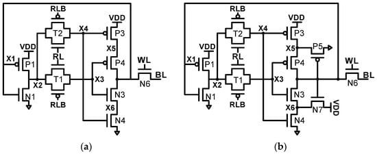
Figure 9.
Schematic of (a) RHD-11 T and (b) RHD-13 T SRAM cell.
RHBD-11 T, RHBD-13 T, RHD-11 T, and RHD-13 T all have full immunity to single node upsets and even have enhanced robustness to multiple node upsets. However, they all suffer from the overhead of using additional control circuitry for the generation of a refresh signal periodically.
In addition, these four structures suffer from larger write and read delays compared to the other designs. For example, when BL is lowered for the data “0” write, M10 in RHBD-11 T or -13 T (P3 and P4 for RHD-11 T or -13 T) should be turned off. However, due to the lengthened feedback path with the use of the pass gate to isolate the node, more time is required to turn off M10 (P3 and P4). For the read operation, the use of a single-ended BL requires a larger voltage drop for sensing, and the read current path inside the memory cell is composed of three-stacked nFETs. Thus, a significant increase in read delay is inevitable.
4. Comparison and Discussion
Table 1 shows an overall summary of the various radiation-hardening SRAM cell designs covered in the previous section, in terms of their delay, power, stability, upset resilience, and control signal generation overhead. HSPICE simulations were performed with ASAP7 finFET technology [22] at 0.7 V. The dynamic power consumption was derived as the average power consumption for the read and write operations with 200 MHz in a 128 × 128 bitcell array. The read and write stabilities were measured in terms of the read static noise margin (RSNM) and word-line write trip voltage (WWTV), respectively. The robustness to SEU was evaluated in terms of the critical charge (QC), which is the minimum charge injected to the storage node to cause a data flip. The bitcell area was derived through the layout performed in the ASAP7 finFET design rule.

Table 1.
Comparison of various radiation-hardening SRAM cell designs.
In Table 1, the trade-offs between different performance aspects in the various designs are clearly shown. Therefore, if one of the SRAM cell designs is to be chosen for a certain application, the most suitable SRAM cell design can be chosen considering the constraints in the environment of the application. In this section, the trade-offs between different bitcell designs are analyzed in depth to provide guidance to design or select the appropriate radiation-hardened SRAM bitcell.
4.1. Design Approaches to Reduce Area/Power
To reduce the area and power overheads of the most conventional design, DICE-12 T, various designs have been proposed. Many structures with a reduced number of transistors—Quatro-10 T, NS-10 T, PS-10 T, RHBD-10 T, QUCCE-10 T—utilize the four storage nodes, while only two storage nodes are accessible through two access transistors. The radiation hardening is realized by causing each of the four storage nodes to be driven to VDD and 0 V by two FETs that are controlled by different nodes. To hold the data, two or more cross-coupled nFETs or pFETs are employed, so that the four storage nodes are configured in the positive feedback. With these structures, the number of required transistors is reduced so that the area and power consumption overhead can be minimized.
However, in these structures, the internal storage nodes exposed to both types of SEU (falling and rising) are directly driven by the cross-coupled nFETs or pFETs that are used to hold the data. Thus, the positive feedback can be easily triggered even with small charge noise, which might lead to a data flip. As a result, these structures—NS-10 T, PS-10 T, and RHBD-10 T in particular—have small values of QC, meaning that they have limited robustness to SEU.
In addition, these structures have limited write ability and enlarged write delays. This is because when the access transistor attempts to change the voltage of a storage node, the contention current is very significant. The reason for this is the configuration for the radiation hardening—the use of different signals for FETs driving one storage node. In addition, the cell designs have only partial resilience to SEU due to the use of the positive feedback structure to hold four storage nodes.
4.2. Design Approaches to Enhance Write Performance and SEU Tolerance
To enhance the write performance, some designs employ four access transistors to render all four storage nodes accessible by bit-lines—WE-Quatro-12 T, RHPD-12 T, RHBD-12 T, and QUCCE-12 T. However, the use of two additional transistors and relevant routing inevitably increases the area and power consumption overhead.
The representative approach to enhance the SEU tolerance is to design the storage node of the bitcell to have SET of only one polarity, either rising or falling. If the node exposed to only falling SET is connected to nFET, the SET will not turn on any transistor, so that the SEU can be prevented. In RHPD-12 T or RHBD-12 T, the use of four access transistors and the location of only nFET or pFET diffusions to drive the storage nodes can provide enhanced tolerance to SEU. However, the use of a single-polarity FET for a specific node inevitably degrades the drivability, because pFET and nFET can only strongly drive 1 and 0, respectively. As a result, the performance and stability are highly degraded in these structures.
4.3. Use of Dynamic Node with Refresh Signal
The use of an isolating dynamic storage node with the refresh operation can guarantee enhanced tolerance to SEU, as in RHPD-11 T and RHD-11 T. In addition, by applying a Schmitt trigger inverter for these structures to form RHPD-13 T and RHD-13 T, even enhanced tolerance for multiple node upsets can be achieved. However, to minimize the area, the single-ended bit-line is used, so the read and write performance is limited. In addition, significant overheads occur in generating the control signals for the refresh operation.
In particular, the write ability is significantly degraded in these structures due to the single-ended structure. In RHBD-11 T and 13 T, M9 is used to mitigate this issue, but it only enhances the “1” write stability. In RBD-11 T and 13 T, due to the use of the nFET pass-transistor instead of the transmission gate as an access transistor, the write ability is also highly limited. This problem might be resolved by employing a pFET header switch as M9 or with the use of the transmission gate, although this approach incurs an additional area overhead.
In future, it will be paramount to design SRAM cells with high read and write performance and with sufficient SEU tolerance. This is because, as mentioned, the previously proposed SRAM cell designs severely suffer from the trade-off between the SEU reliability and read/write performance. In addition, as technology scales down, designs to tackle the multiple node upset errors will carry increased importance. However, the use of a dynamic node with refresh signals would be highly limited in the sub 10-nm technology nodes due to increased uncertainty and decreased device dimensions. Thus, SRAM cell designs with tolerance to multiple node upset in the static manner are required.
Author Contributions
T.Y., J.P. and H.J.: literature survey and investigation, comparative analysis, and figure design; H.J.: project supervision. All authors have read and agreed to the published version of the manuscript.
Funding
This research was supported by the MSIT (Ministry of Science and ICT), Korea, under the ITRC (Information Technology Research Center) support program (IITP-2022-RS-2022-00156225) supervised by the IITP (Institute for Information & Communications Technology Planning & Evaluation) and the Basic Science Research Program through the National Research Foundation of Korea (NRF), funded by the Ministry of Education (No. 2018R1A6A1A03025242).
Institutional Review Board Statement
Not applicable.
Informed Consent Statement
Not applicable.
Data Availability Statement
Not applicable.
Conflicts of Interest
The authors declare no conflict of interest.
References
- Saxena, G.; Agrawal, R.; Sharma, S. Single event upset (SEU) in SRAM. Int. J. Eng. Res. Appl. 2013, 3, 2171–2175. [Google Scholar]
- McLain, M.L.; Barnaby, H.J.; Esqueda, I.S.; Oder, J.; Vermeire, B. Reliability of High Performance Standard Two-Edge and Radiation Hardened by Design Enclosed Geometry Transistors. In Proceedings of the 2009 IEEE International Reliability Physics Symposium, Montreal, QC, Canada, 26–30 April 2009; pp. 174–179. [Google Scholar]
- Qi, C.; Xiao, L.; Wang, T.; Li, J. A highly reliable memory cell design combined with layout-level approach to tolerant single-event upsets. IEEE Trans. Device Mater. Reliab. 2016, 16, 388–395. [Google Scholar] [CrossRef]
- Petrosyants, K.O.; Sambursky, L.M.; Kharitonov, I.A.; Lvov, B.G. Radiation-Induced Fault Simulation of SOI/SOS CMOS LSI’s Using Universal Rad-SPICE MOSFET Model. J. Electron. Test. 2017, 33, 37–51. [Google Scholar]
- Blum, D.R.; Delgado-Frias, J.G. Schemes for eliminating transient-width clock overhead from SET-tolerant memory-based systems. IEEE Trans. Nucl. Sci. 2006, 53, 1564–1573. [Google Scholar] [CrossRef]
- Reviriego, P.; Maestro, J.A.; Flanagan, M.F. Error detection in majority logic decoding of euclidean geometry low density parity check (EG-LDPC) codes. IEEE Trans. Very Large Scale Integr. Syst. 2012, 21, 156–159. [Google Scholar]
- She, X.; Li, N.; Jensen, D.; Waileen. SEU tolerant memory using error correction code. IEEE Trans. Nucl. Sci. 2012, 59, 205–210. [Google Scholar]
- Poolakkaparambil, M.; Mathew, J.; Jabir, A.M.; Pradhan, D.K.; Mohanty, S. BCH Code Based Multiple Bit Error Correction in Finite Field Multiplier Circuits. In Proceedings of the 2011 12th International Symposium on Quality Electronic Design, Santa Clara, CA, USA, 14–16 March 2011; pp. 1–6. [Google Scholar]
- Naseer, R.; Draper, J. Parallel Double Error Correcting Code Design to Mitigate Multi-Bit Upsets in SRAMs. In Proceedings of the ESSCIRC 2008–34th European Solid-State Circuits Conference, Edinburgh, UK, 15–19 September 2008; pp. 222–225. [Google Scholar]
- Choi, H.; Liu, W.; Sung, W. Vlsi implementation of BCH error correction for multilevel cell NAND flash memory. IEEE Trans. Very Large Scale Integr. Syst. 2009, 18, 843–847. [Google Scholar]
- Pradhan, D.K.; Stiffler, J.J. Error-correcting codes and self-checking circuits. Computer 1980, 13, 27–37. [Google Scholar] [CrossRef]
- Calin, T.; Nicolaidis, M.; Velazco, R. Upset hardened memory design for submicron CMOS technology. IEEE Trans. Nucl. Sci. 1996, 43, 2874–2878. [Google Scholar] [CrossRef]
- Jin Sang, K.; Ik Joon, C. We-quatro: Radiation-hardened SRAM cell with parametric process variation tolerance. IEEE Trans. Nucl. Sci. 2017, 64, 2489–2496. [Google Scholar]
- Jung, I.-S.; Kim, Y.-B.; Lombardi, F. A Novel Sort Error Hardened 10T SRAM Cells for Low Voltage Operation. In Proceedings of the 2012 IEEE 55th International Midwest Symposium on Circuits and Systems (MWSCAS), Boise, ID, USA, 5–8 August 2012; pp. 714–717. [Google Scholar]
- Jing, G.; Lei, Z.; Yu, S.; Huiliang, C.; Hai, H.; Tianqi, W.; Chunhua, Q.; Rongsheng, Z.; Xuebing, C.; Liyi, X.; et al. Design of area-efficient and highly reliable RHBD 10T memory cell for aerospace applications. IEEE Trans. Very Large Scale Integr. (VLSI) Syst. 2018, 26, 991–994. [Google Scholar]
- Prasad, G.; Mandi, B.C.; Ali, M. Power optimized SRAM cell with high radiation hardened for aerospace applications. Microelectron. J. 2020, 103, 104843. [Google Scholar] [CrossRef]
- Zhao, Q.; Peng, C.; Chen, J.; Lin, Z.; Wu, X. Novel write-enhanced and highly reliable RHPD-12T SRAM cells for space applications. IEEE Trans. Very Large Scale Integr. Syst. 2020, 28, 848–852. [Google Scholar] [CrossRef]
- Jing, G.; Lei, Z.; Wenyi, L.; Hai, H.; Shanshan, L.; Tianqi, W.; Liyi, X.; Zhigang, M. Novel radiation-hardened-by-design (RHBD) 12T memory cell for aerospace applications in nanoscale CMOS technology. IEEE Trans. Very Large Scale Integr. Syst. 2017, 25, 1593–1600. [Google Scholar]
- Jiang, J.; Xu, Y.; Zhu, W.; Xiao, J.; Zou, S. Quadruple cross-coupled latch-based 10T and 12T SRAM bit-cell designs for highly reliable terrestrial applications. IEEE Trans. Circuits Syst. I: Regul. Pap. 2018, 66, 967–977. [Google Scholar]
- Lin, S.; Kim, Y.-B.; Lombardi, F. Analysis and design of nanoscale CMOS storage elements for single-event hardening with multiple-node upset. IEEE Trans. Device Mater. Reliab. 2011, 12, 68–77. [Google Scholar]
- Ramin, R.; Bahar, A.; Mahmoud, T.; Mahdi, F. Design of robust SRAM cells against single-event multiple effects for nanometer technologies. IEEE Trans. Device Mater. Reliab. 2015, 15, 429–436. [Google Scholar]
- Clark, L.T.; Vashishtha, V.; Shifren, L.; Gujja, A.; Sinha, S.; Cline, B.; Ramamurthy, C.; Yeric, G. ASAP7: A 7-nm FinFET predictive process design kit. Microelectron. J. 2016, 53, 105–115. [Google Scholar] [CrossRef]
Publisher’s Note: MDPI stays neutral with regard to jurisdictional claims in published maps and institutional affiliations. |
© 2022 by the authors. Licensee MDPI, Basel, Switzerland. This article is an open access article distributed under the terms and conditions of the Creative Commons Attribution (CC BY) license (https://creativecommons.org/licenses/by/4.0/).