Article

Buckling of Composite Structures with Delaminations—Laminates and Functionally Graded Materials

Department of Physics, Cracow University of Technology, 31-155 Kraków, Poland
Appl. Sci. 2022, 12(22), 11408; https://doi.org/10.3390/app122211408
Submission received: 14 October 2022 / Revised: 1 November 2022 / Accepted: 3 November 2022 / Published: 10 November 2022

Abstract

:
In the present paper, buckling problems of constructions with single delamination are examined. Structures were made of unidirectional laminates and functionally graded materials (FGM). Two types of delaminations (closed and opened) were both investigated in experiments both in rectangular plates and axi-symmetric shells. The first part of the work is devoted to the formulation of contact problems (embedded, closed delaminations) with the aid of various functional inequalities. Then, computational models are discussed. To study the influence of the variable material configuration of FGMs, the fourth-order plate/shell relations were adopted. Finally, three particular problems examined are the buckling of flat rectangular plates, spherical shells, and compressed rectangular plates with elliptical delaminations. The experiments were conducted using imperfection sensitivity analysis and post-buckling non-linear analysis. The results demonstrate that the unsymmetric configurations of FGM structures lead to the reduction of buckling loads for structures with delaminations. For FG structures, those effects are described by the simple coefficient. Linear fracture mechanics were employed to distinguish the form of unilateral boundary problems (closed or opened). In the first case, the stable variations of the strain energy release rate GI with the delamination length variations were observed, whereas in the second case the unstable variations were observed.

1. Introduction

The invention, conception and manufacturing of functionally graded materials (FGMs) introduce a new class of composite materials that should be considered in the investigations of structural behaviour and their response to loading and boundary conditions.
The possible configurations of functionally graded materials are presented in Figure 1.
For discontinuous gradients, three types of gradients are introduced: (1) gradient composition, (2) gradient microstructure and (3) gradient porosity.
For FGMs, the review of possible compositions of materials and their applications is discussed in Refs. [1,2,3,4,5,6,7,8,9,10].
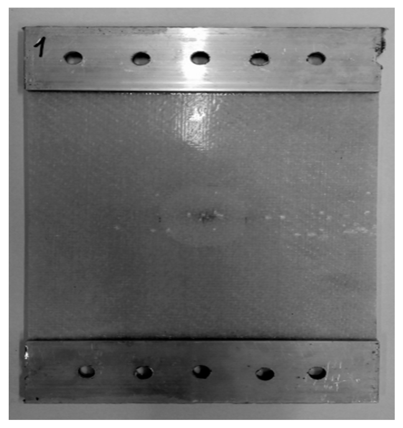
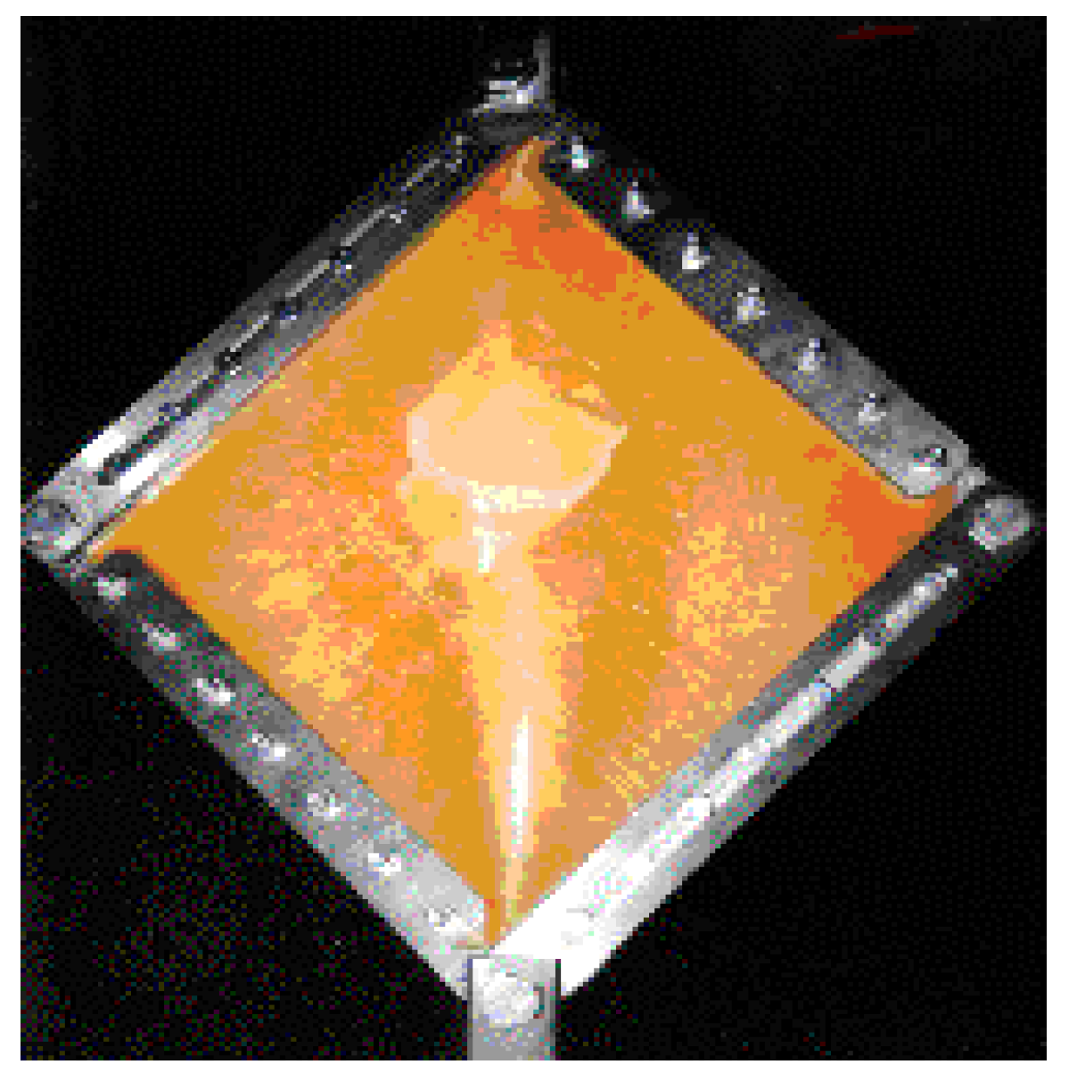
Multi-layered composite structures (laminates and those made of functionally graded materials or nanostructures) may be subject to various forms of local (matrix, fiber cracking, fiber separation, or delamination) or global (buckling or free vibration) failure. In the case of the simultaneous occurrence of global and local forms of damage, the mathematical and numerical description of the deformation and final failure of the analyzed structures is drastically changed and becomes difficult—see the experimental results shown in Figure 2 and Figure 3. They demonstrate the differences between deformations for closed and opened delaminations. The detailed description of experimental results both for static and fatigue loads is presented in Refs. [11,12]—see also Appendix A.
The delamination associated with the buckling of structures can be classified into types of strips: rectangular, circular, and elliptical. The effect of contact between separated layers (sub-laminates) is also considered. Several papers investigate the growth of cracks and delaminations in flat plates and cylindrical shells with axi-symmetric delaminations [1,2,3,4,5,6,7,8,9,10]. The problems of delamination failure are considered both under static, impact and fatigue loads. The research analysis can be divided into the following subjects:
  • For predicting the initiation of delamination failure, it is possible to apply analytical or numerical methods (finite element modeling); see, e.g., Ref. [11] combined with the formulation of appropriate strength criteria presented in Appendix A—see Refs. [12,13];
  • Buckling analysis—the length and the form of the delaminated region are prescribed in advance and then the carrying capacity of structures (mainly plates), understood in the sense of local buckling, is studied, where both single [14] and multiple [15] delaminations are considered;
  • Contact problems: during the loading or unloading process, the initially opened region of delamination can both grow and/or shrink; however, in the latter case, the strict and concise contact (even frictionless) analysis is required—see, for instance, 1D analysis, 2D analysis and 3D analysis Refs. [16,17,18,19,20,21,22,23,24,25,26,27,28,29,30];
  • Different problems in conjunction with the impact/fatigue delamination growth (laminates and FGMs) are also investigated. Several authors use the finite element method and cohesive elements approach to describe various modes of impact/fatigue loading [31,32]. Modeling of impact/fatigue problems and damage propagation in delaminated composite structures are also discussed in Refs. [33,34,35,36,37,38,39,40,41].
However, it should be pointed out that the correct and accurate solution to the above problems requires a different approach due to the existence of unilateral boundary conditions. The mathematical formulation of such problems is carried out with the use of variational inequalities; see Panagiotopoulos [42], Muc [43].
The importance and complexity of the numerical approach are underlined in different papers [44,45,46,47,48,49] where various numerical methods have been studied characterizing the application of dual methods, nonlinear programming methods, asymptotic methods, and the Bubnov–Galerkin and Rayleigh–Ritz methods.
The aim of the present paper is two-fold:
  • To demonstrate and discuss the formulation of the buckling of laminated and functionally graded structures with 1D and 2D delaminations;
  • To compare the results for composite structures made of laminates or functionally graded materials.
The analysis was conducted with the aid of 2D higher-order plate/shell theories, formulated in Ref. [50], and of 3D FE formulations. Linear fracture mechanics are adopted (the strain energy release factor GI–see Appendix A) to distinguish the form of unilateral boundary conditions.

2. Kinematic Relations

The 3D displacements are defined in the following way:
U ˜ 1 ( ξ 1 ,   ξ 2 , ξ 3 ) = u 1 ( ξ 1 ,   ξ 2 ) ( 1 + z R 1 ) + z ϕ 1 + z 2 ψ 1 + z 3 γ 1 + z 4 θ 1 U ˜ 2 ( ξ 1 ,   ξ 2 , ξ 3 ) = u 2 ( ξ 1 ,   ξ 2 ) ( 1 + z R 2 ) + z ϕ 2 + z 2 ψ 2 + z 3 γ 2 + z 4 θ 2 U ˜ 3 ( ξ 1 ,   ξ 2 , ξ 3 ) = u 3 ( ξ 1 ,   ξ 2 ) + z χ 1 + z 2 χ 2 + z 3 χ 3
The non-linear strain components are expressed as follows [51,52,53]:
ε 11 = e 11 + 1 2 [ e 11 2 + ( 1 2 e 12 + ω 2 ) 2 + ( 1 2 e 13 ω 2 ) 2 ] , ε 12 = e 12 + e 11 ( 1 2 e 12 ω 3 ) + e 22 ( 1 2 e 12 + ω 3 ) + ( 1 2 e 13 ω 2 ) ( 1 2 e 23 + ω 1 ) , e 11 = 1 H 1 ( U ˜ 1 ξ 1 + 1 H 2 H 1 ξ 2 U ˜ 2 + 1 H 3 H 1 ξ 3 U ˜ 3 ) , 2 ω 1 = 1 H 1 H 2 [ ( H 3 U ˜ 3 ) ξ 2 ( H 2 U ˜ 2 ) ξ 3 ] , e 12 = e 21 = H 2 H 1 ξ 1 ( U ˜ 2 H 2 ) + H 1 H 2 ξ 2 ( U ˜ 1 H 1 ) , H γ = A γ ( 1 + z R γ ) , H 3 = 1 , γ = 1 , 2 .
The strains ε13, ε22, ε23, and ε33 are derived by the classical cyclic permutation of the subscripts 1, 2, and 3, whereas the non-linear terms are introduced in the following way:
ε 11 n o n l = 1 2 ( u 3 A 1 ξ 1 ) 2 , ε 22 n o n l = 1 2 ( u 3 A 2 ξ 2 ) 2 , ε 12 n o n l = 2 u 3 A 1 A 2 ξ 1 ξ 2
The strain components are functions of the parameters u, v, w, ϕ1, ϕ2, χ1, χ2, χ3—see Ref. [50].
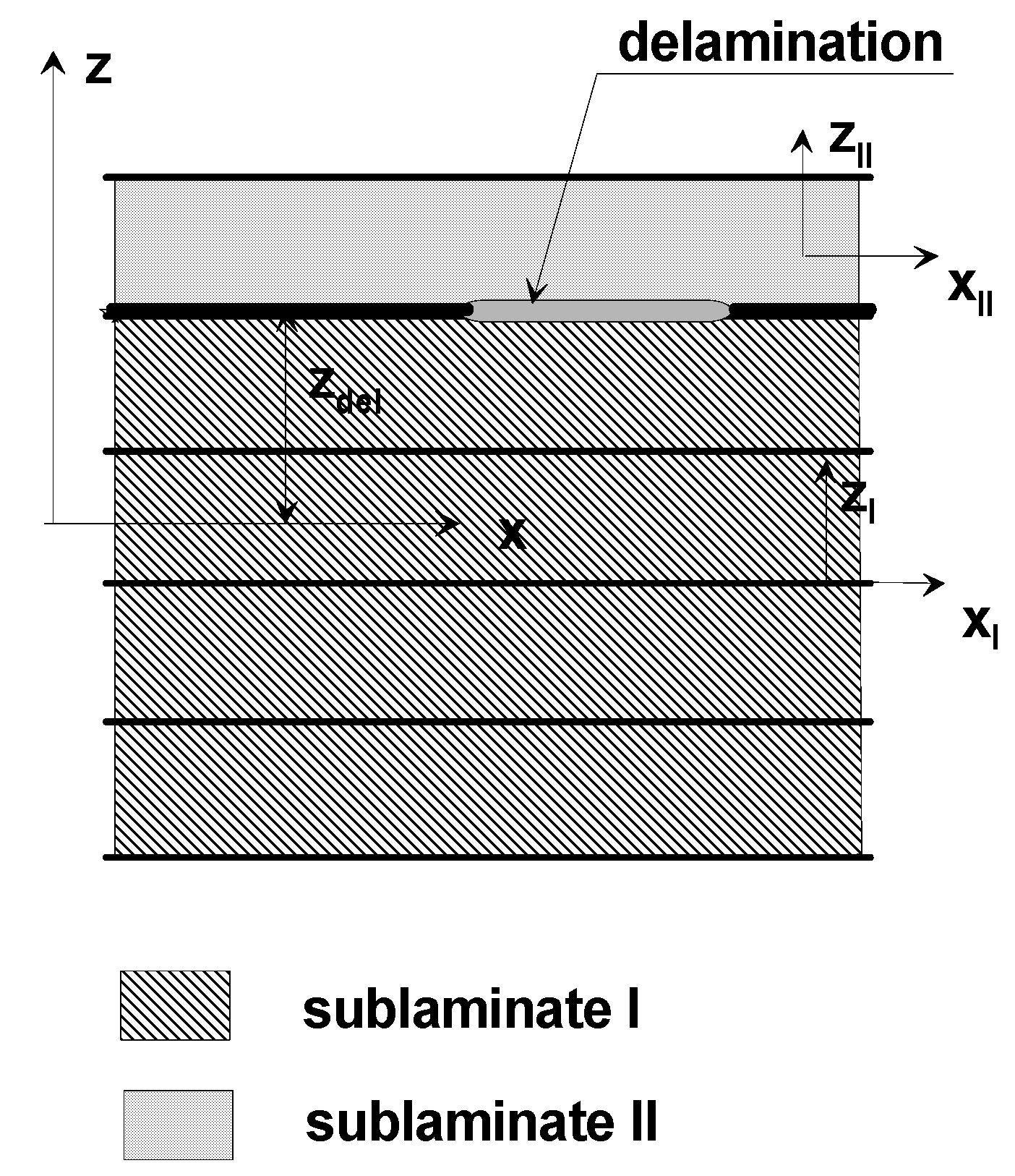
We shall consider composite structures containing an embedded delamination. The global system of coordinates is defined in the mid-surface of the structure, as illustrated in Figure 4. As is normal for laminates, the material system of coordinates coincides with the fiber direction. The applied formulation of variational principles characterized in the third section is based on the following geometrical and material assumptions: (1) the displacement discontinuities can occur in the delaminated regions only; (2) both for laminates and FGMs, material is linearly elastic—see the Section 3; (3) the geometrical nonlinearities are taken into account in the form of large deformations, as in Equation (3), and not strains; (4) the stretching of the normal is considered in the form written in Equation (1).
The description of fracture, buckling and post-buckling behaviour of composite structures with delaminations can be carried out in two general ways: (1) a 3D approach—usually the finite element method; and (2) 2D analytical approximations. In the latter case, the form and the correctness of the analysis depend mainly on the form of the prescribed 2D approximations of 3D displacements.
The model of the delamination is usually employed in the analysis of the delamination sensitivity where the imperfection is added to the normal displacements, i.e.:
U ˜ 3 ( ξ 1 ,   ξ 2 , ξ 3 ) = u 3 ( ξ 1 ,   ξ 2 ) + z χ 1 + z 2 χ 2 + z 3 χ 3 + w * ( ξ 1 , ξ 2 )
w * ( ξ 1 , ξ 2 ) represents a small deviation of the plate/shell middle plane from a flat shape. The imperfections of the structure, considering the simply supported boundary conditions, are assumed as:
w ( ξ 1 , ξ 2 ) = δ sin ( π ξ 1 / a ) sin ( π ξ 2 / b )
where the coefficient δ varies between 0 and 1, and δ represents the amplitude of the imperfection. The above representation of the delamination form is commonly used in the literature—see, e.g., [17,54,55,56].
The proposed formulation is applied to the analysis of:
One-dimensional axisymmetric spherical shells, R1 = R2 = R, where the coordinate ξ 2 variable is eliminated;
Two-dimensional flat rectangular plates, Cartesian rectangular coordinates—R1 , R2 .

3. A Brief Description of Contact Problems Associated with Local Buckling

The description of contact problems for composite structures can be divided into two classes:
  • One-dimensional contact problems; the delamination is represented by a single line that separates (or not) the sub-laminates—see Figure 5;
  • Two-dimensional contact problems; the delamination is described by a surface—see Figure 6.
The first two modes plotted in Figure 5a,b occur as the upper sub-laminate is thin and the area of the imperfection (delamination) is large. The third mode (Figure 5c) is observed as the delamination has a small area and the imperfection is located deeper in the structure. In the latter case, the delamination can be closed and its effects are connected with contact reactions between upper and lower sub-laminates—see, e.g., Refs. [57,58].
The failure mode and loads are functions of the delamination size and form— see Equation (5).
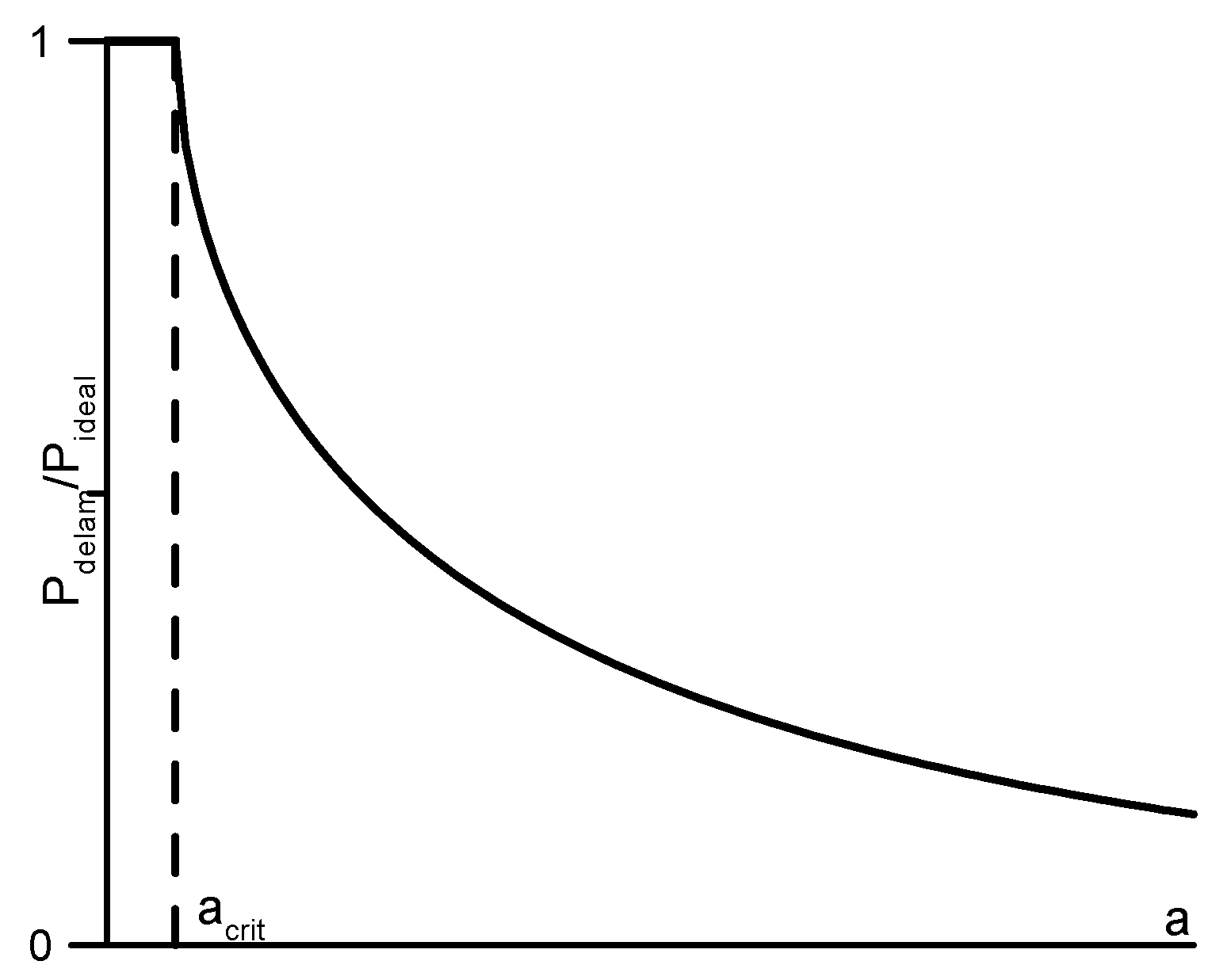
For 1D delaminations, Figure 7 shows two characteristic cases: when the delamination length a < acrit is not the critical length and does not cause local sub-laminate stability loss, and the second, when sub-laminate stability loss above the critical length occurs. Therefore, it is obvious that the construction of models characterizing the local loss of stability by the sub-laminate should allow for the determination of both the critical length of acrit delamination as a function of geometrical and material parameters, as well as the assessment (after local buckling) of the degree of decrease in the value of the critical load as a function of the length of the gap a (or the surface area A for two-dimensional delamination)—see Figure 7.
To evaluate the curve plotted in Figure 8, the imperfection sensitivity method was adopted. In Ref. [59] it is demonstrated that buckling loads can be derived with the aid of the lower bound method, where the form of the imperfection is described by Equation (5). Varying the parameters characterizing the imperfection function, it is possible to find the lower bound corresponding to the curve plotted in Figure 8.

4. Variational Formulations of Contact Problems with Local Buckling

The composite structure represents a 3D body (laminates or functionally graded material, FGM) that is a space occupied by layered structures k = 1 N V k , where Vk is a space occupied by the individual k-th layer description of the layered structures.
The functional characterizing composite structures J can be divided into three parts:
J = J e n + J b b c + J u b c
The first part, Jen, corresponds to the strain (internal) energy. The classical approaches are presented below:
Hu–Washizu
J e n ( σ , e , u ) = k = 1 N [ V ( k ) ( 1 2 [ e ( k ) ] T r [ Q ( k ) ] [ e ( k ) ] [ σ ( k ) ] T r [ e ( k ) ] + [ σ ( k ) ] T r [ e ( k ) ] T r [ [ e ( k ) ] ( u α ( k ) ) ] ) ] d V
Hellinger–Reissner
J e n ( σ , e ) = k = 1 N [ V ( k ) ( 1 2 [ σ ( k ) ] T r ( [ Q ( k ) ] 1 ) T r [ σ ( k ) ] + [ σ ( k ) ] T r [ e ( k ) ( u α ( k ) ) ] ) ] d V
Lagrange
J e n ( u ) = k = 1 N [ V ( k ) ( 1 2 [ [ e ( k ) ] ( u α ( k ) ) ] T r [ Q ( k ) ] [ e ( k ) ( u α ( k ) ) ] ) ] d V
where σ is the stress tensor, e is the strain tensor and u denotes the components of the displacements. The relation between stresses and strains is described by the linear elastic relation. For laminated composites, the traditional relation takes the classical form presented, e.g., by Jones [60]. For FGMs, the physical relation takes the following form:
[ Q ( z ) ] = E ( z ) ( 1 + ν ) [ 1 ν 1 2 ν ν 1 2 ν ν 1 2 ν 0 0 0 ν 1 2 ν 1 ν 1 2 ν ν 1 2 ν 0 0 0 ν 1 2 ν ν 1 2 ν 1 ν 1 2 ν 0 0 0 0 0 0 0.5 0 0 0 0 0 0 0.5 0 0 0 0 0 0 0.5 ]
where:
E ( z ) / E b = [ ( E t / E b 1 ) f i n d ( z ) + 1 ] f i n d ( z ) = ( z h + 1 2 ) n
The second term in the functional (6) corresponds to the bilateral boundary conditions formulated in the equality form:
σ ( α β ) ( k ) n β ( k ) = s α , u j α ( k ) = W j α   on   S , k = 1   or   k = N
They determine values of the displacement field W or the distributed external loads s.
The third component in the functional J (6) represents the unilateral boundary conditions, i.e., the kinematic boundary conditions between layers:
u α ( k ) ( x , y , z l ) = u α ( k 1 ) ( x , y , z l )
and transverse shear and normal stress continuity conditions at the contact interfaces:
σ α 3 ( k ) ( x , y , z l ) = σ α 3 ( k 1 ) ( x , y , z l ) ,   α = 1 , 2 , 3
They take the following forms:
the Hu–Washizu approach
J u b c = l = 1 N 1 ( S ( l , l + 1 ) [ u ( l ) u ( l + 1 ) ] [ σ 3 ( l , l + 1 ) ] d S )
the Hellinger–Reissner approach
J u b c = l = 1 N 1 ( S ( l , l + 1 ) [ u ( l ) u ( l + 1 ) ] [ σ 3 ( l , l + 1 ) ] d S )
the Lagrange approach
J u b c = l = 1 N 1 ( S ( l , l + 1 ) [ u ( l ) u ( l + 1 ) ] [ λ ] d S )
where λ denotes the Lagrange multiplier.

5. Computational Models

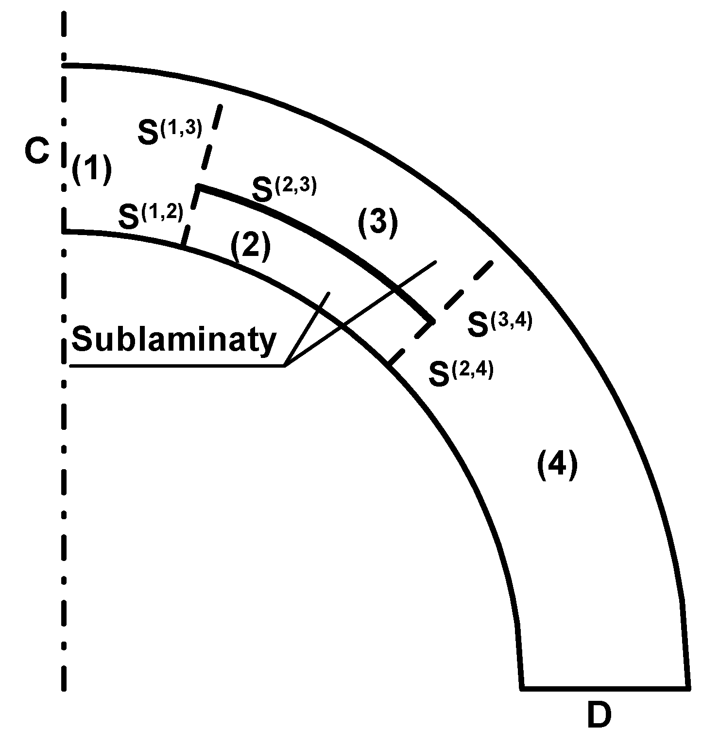
The construction of composite structures with delamination is presented in Figure 8. The total area V is divided into three (Figure 5a) or four parts (Figure 5b,c). Two of the areas (1) and (4) represent the domains without delaminations, and the domains (2) and (3) correspond to the division of the thickness along the line of the delamination (unilateral boundary condition). For each of the areas (2) and (3), the independent sets of kinematical relations is formulated, whereas in the areas (1) and (4), the global system of coordinates is used. A similar approach is introduced in Refs. [17,61].
Correct numerical modeling of the problem of development of delamination and subsequent loss of stability by sub-laminates requires taking into account the following factors in the analysis:
The application of the large displacement (or deformation) option to determine the bifurcation point;
Structure modeling using 2D or 3D elements is necessary for the analysis of the sub-laminate buckling state, because the classic FEM packages contain only shell elements based on the 3D or first-order transverse shear theory, and as stated previously, in delamination problems, the theories of higher-order shells should be used;
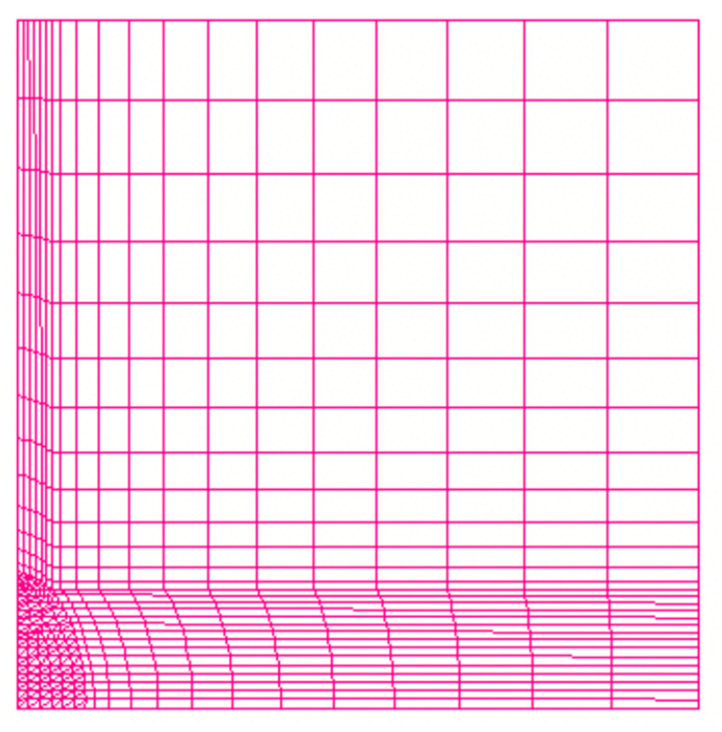
The area where delamination occurs and its surroundings should be discretized using 2D or 3D elements with a triangular base to better approximate, especially at the edge of delamination, the values of the G energy release factors;
Along the thickness of FGMs, the division should include 15 to 20 FE since the material properties vary significantly along the coordinate z—see Equation (10).
The mechanical properties of materials used in computations are written in Table 1.

6. Three Parametrical Shell Theories

The simplest Love–Kirchhoff hypothesis (the three parametrical shell theory) can be applied to observe and consider the unilateral constraint problems for 2D laminated structures. The form of the displacement distributions (1) is reduced to:
U ˜ 1 ( ξ 1 ,   ξ 2 , ξ 3 ) = u 1 ( ξ 1 ,   ξ 2 ) ( 1 + z R 1 ) + z u 3 ξ 1 U ˜ 2 ( ξ 1 ,   ξ 2 , ξ 3 ) = u 2 ( ξ 1 ,   ξ 2 ) ( 1 + z R 2 ) + z u 3 ξ 2 U ˜ 3 ( ξ 1 ,   ξ 2 , ξ 3 ) = u 3 ( ξ 1 ,   ξ 2 )
The strain and stress components can be derived from the Equations (2), (3) and (10).

6.1. The Flat Rectangular Plate with An Infinite Width

Let us analyse the simplest case of the unilateral constraint problem for the flat rectangular plate. The problem is reduced to the 1D problem as explained in Ref. [59]. In the plate shown in Figure 9, the length of the delamination is equal to a.
At the edge of the delaminated zone, one can write the continuity conditions for membrane forces N:
N(1) = N(2) + N(2)
bending moments M:
M(1) = M(2) + M(3) − 0.5 N(2)t(2) − 0.5 N(3)t(3)
and axial displacements u:
u(3)(b + a,0) − u(3)(b,0.5 t(2))= u(2)(b + a,0) − u(2)(b, − 0.5 t(3))
For the L-K hypothesis, the stress–strain relations take the following form:
M ( i ) = ( B x x A x x ) ( i ) N ( i ) ( D x x B x x 2 A x x ) ( i ) w ( i ) , x x ,   i = 1 ,   2 ,   3
A x x ( i ) = E x x ( i ) d z ( i ) , B x x ( i ) = E x x ( i ) z ( i ) d z ( i ) , D x x ( i ) = E x x ( i ) z ( i ) 2 d z ( i )
Assuming that the buckling mode takes the local buckling form (see Figure 5a) and the symmetry concerning the plate coordinate x the fundamental differential equations (in the (1), (2), (3) and (4) domains (Figure 9)) can be written in the classical way valid for 1D beams:
( N x x ( i ) ) , x = 0 , ( M x x ( i ) ) , x x = P ( i ) u 3 ( i ) , x x , ( i ) = 1 , 2 , 3 , 4
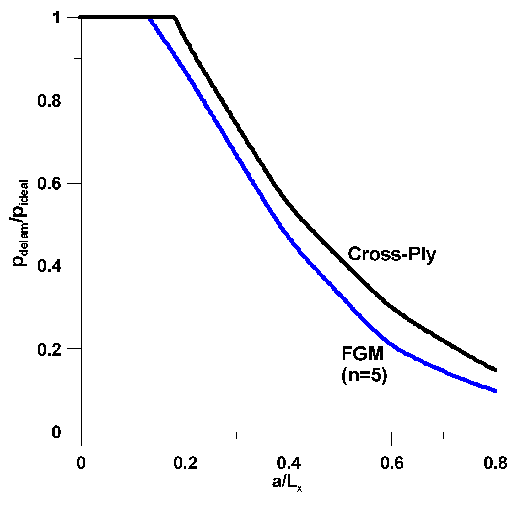
Figure 10 shows values of the critical pressure with a symmetric delamination for several delamination length parameters. The buckling load drops drastically as a is higher than the dimensionless thickness of the delaminated zone h(3)/h(1). The decrease of buckling loads is much more significant for plates made of FGMs.
For the analysed case, the strain energy release rate GI can be derived in an analytical or numerical way—see Appendix A. As may be seen in Figure 10, the small value of the strain energy release rate GI is associated with a catastrophic growth of the delamination length. For higher values of GI, the delamination zone is also unstable; however, it becomes stable for small values of the a/Lx ratio. It will be discussed later for spherical shells.

6.2. Axi-Symmetric Spherical Shells under External Pressure

The buckling of delaminated spherical shells and segments has also been studied in the literature [17,62,63,64,65,66,67,68]. The investigations deal with the analysis of shallow shells [17,62,63,64,65,66,67] or spherical shell segments [68].
The cross-section of spherical shells is presented in Figure 11. The shell geometry is characterized by the shallowness parameter ρ defined below.
ρ = 12 ( 1 ν 12 ν 21 ) 4 a R h .
For isotropic (quasi-isotropic) material properties, the dimensionless value of the external buckling pressure is described by the following relation:
p dim = 2 E q u a s i 3 ( 1 ν 2 ) ( h R ) 2
The forms of the spherical shells with delaminations are plotted in Figure 12.
For shallow shells, the fundamental relations are presented and discussed in Refs. [50,59,69].
M Δ 2 u 3 1 R Δ f 1 ξ 1 ( d f d ξ 1 n 2 ξ 1 f ) d 2 u 3 d ξ 1 2 1 ξ 1 ( d u 3 d ξ 1 n 2 ξ 1 u 3 ) d 2 f d ξ 1 2 + 2 n 2 ξ 1 2 ( d f d ξ 1 n 2 ξ 1 f ) ( d u 3 d ξ 1 n 2 ξ 1 u 3 ) p z n = 0 , M = D ˜ B ˜ 2 ( 1 ν 2 ) A ˜
1 A ˜ Δ 2 f + 1 R Δ u 3 n 2 ξ 1 2 ( d u 3 d ξ 1 1 ξ 1 u 3 ) 2 + ( d u 3 d ξ 1 n 2 ξ 1 u 3 ) d 2 u 3 d ξ 1 2 = 0
Δ is the Laplace operator, and f denotes the Airy stress function. The above relations are reduced to the eight-order differential equation with respect to the normal displacement u3(ξ1).
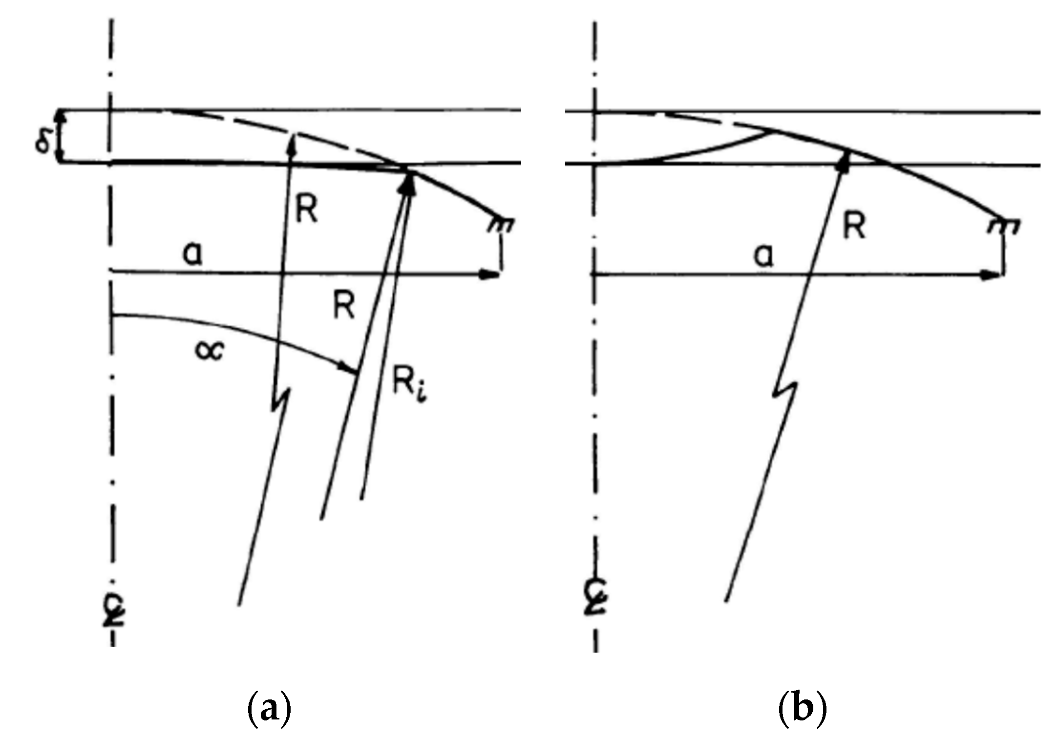
The main goal of the present section is to characterize the influence of the form of delaminations on the reduction of buckling pressures occurring for ideal/perfect spherical shells. The analysis was carried out via imperfection sensitivity analysis to determine the behaviour analogous to the curve plotted in Figure 7, i.e., to find the distributions of buckling pressures with respect to the values of parameters qk describing the shapes of geometrical imperfections plotted in Figure 13:
Min pcr(qk) k = 1, 2, …, K
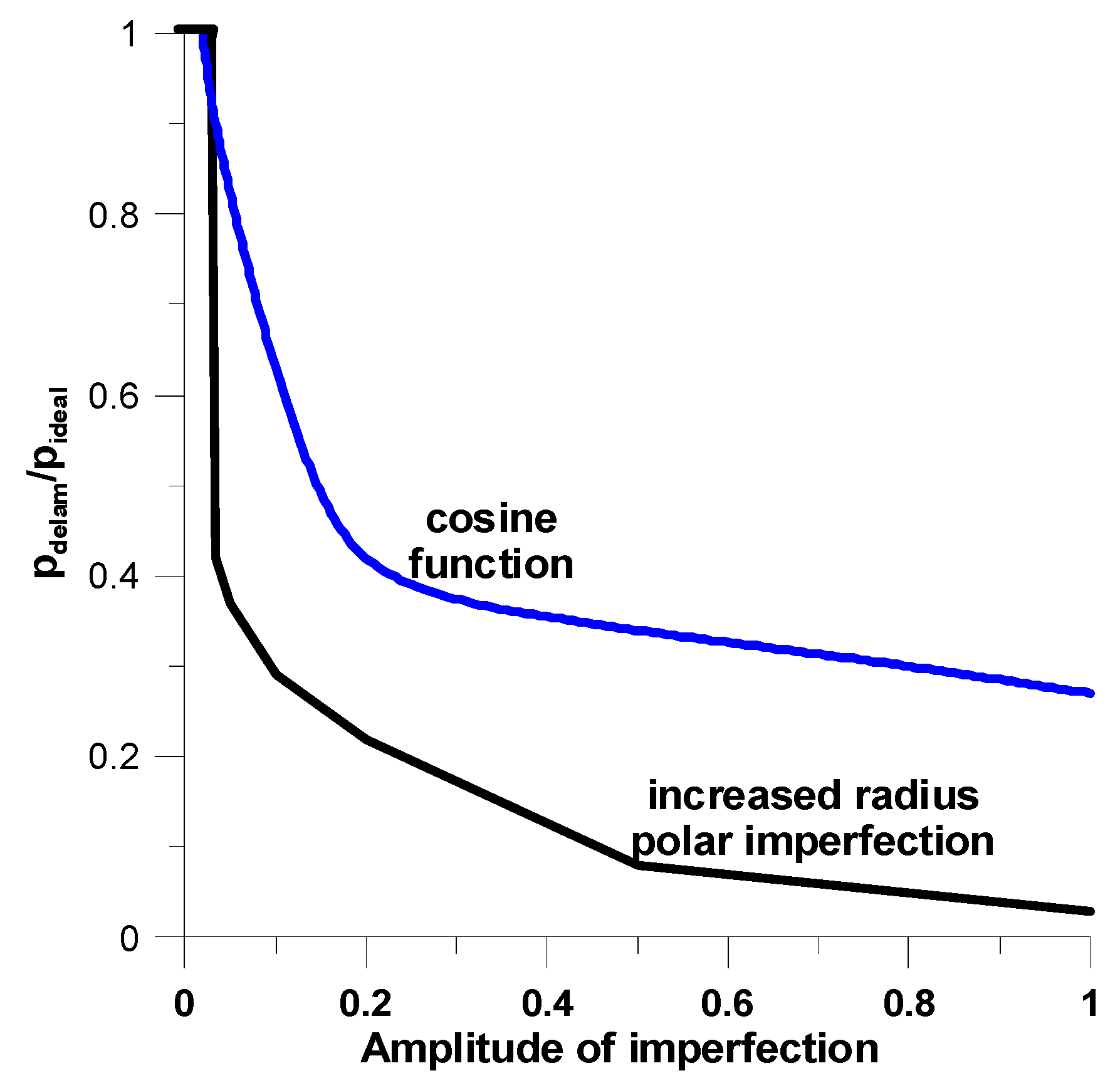
The buckling pressures of spherical shells were derived with the use of the Bubnov–Galerkin method. The detailed form of the series expansions is discussed in Refs. [59,69]. Buckling pressures are much more sensitive to increased radius polar imperfections—see Figure 14. For cross-ply and FGMs, the values of buckling loads are almost identical due to the value of thickness ratio h/R.

7. Numerical Examples for Thicker Structures; 2-D Higher-Order or 3-D Approaches

For thicker structures using the above (higher-order or 3D) formulations, it is possible to solve various issues of delaminated composite structures with local buckling. The problems shown below deal with single delamination.

7.1. Axi-Symmetric Shells under External Pressure

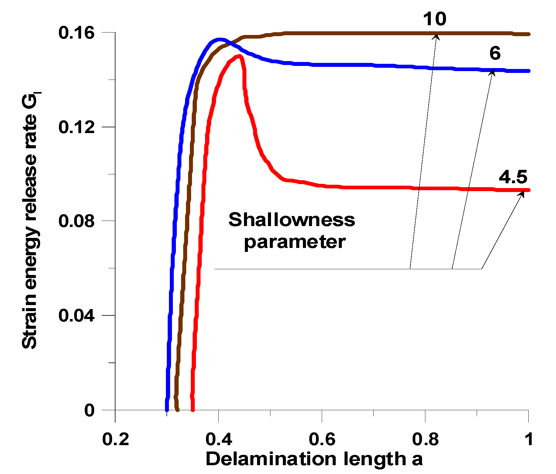
For shallow spherical shells (the small ρ), the buckling mode corresponds to the axisymmetric collapse. As the value ρ increases, the buckling mode becomes bifurcation buckling—see Refs. [50,59]. It is necessary to verify the possible buckling modes for structures subjected to unilateral constraints. We propose herein to adopt the criteria discussed in Appendix A. However, this is a complicated task due to the existing scatter of material properties characterizing failure stresses in Equation (A1) or to postulate the explicit form of the functions (A2), (A3) or (A11). Therefore, we propose to evaluate the strain energy rates with the aid of the finite element package Nisa II Endure. Since the shear effects are negligibly small (see Figure A1) only the tension component GI was computed. Figure 15 represents the variations of the strain energy release rates GI with the single delamination length a.
The distributions of the values demonstrate the influence of the shallowness parameter ρ. For small values, stable behaviour is observed, i.e., the growth and the decrease. For higher values, stable deformations are observed. Increasing the value of ρ, stable behaviour is again observed that corresponds to the state plotted in Figure 15. The analysis conducted in Ref. [17] illustrates the influence of the parameter ρ on the shell deformations.
As may be observed in Figure 16 for the cases plotted in Figure 16b,c, the unilateral boundary conditions of Equations (15)–(17) should be taken into account in the numerical analysis.
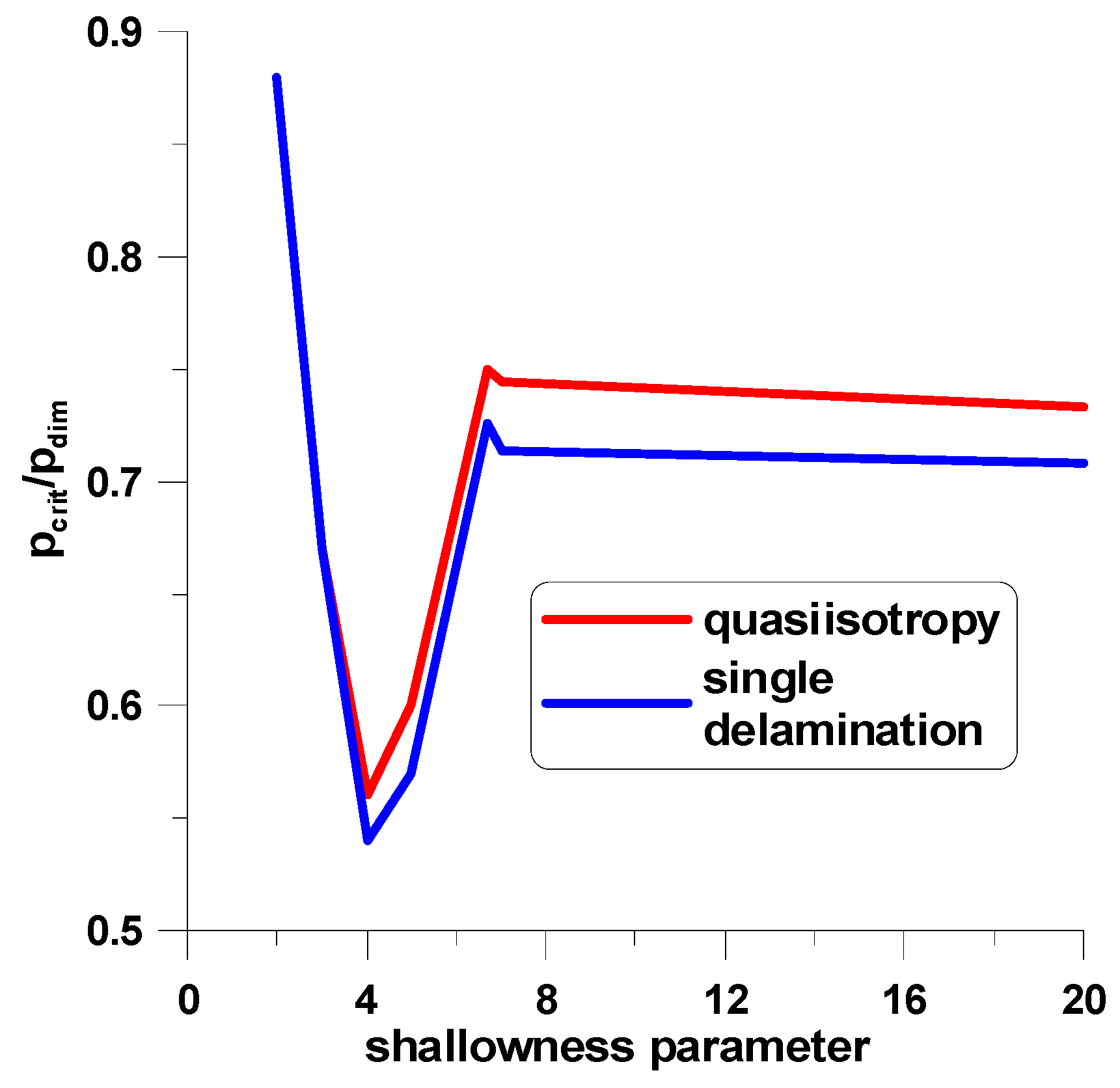
The variations of buckling pressures with the shallowness parameter are plotted in Figure 17 for laminated shells. The single delamination reduces values of buckling pressures. The buckling forms of such structures are plotted in Figure 5—see also Ref. [50].
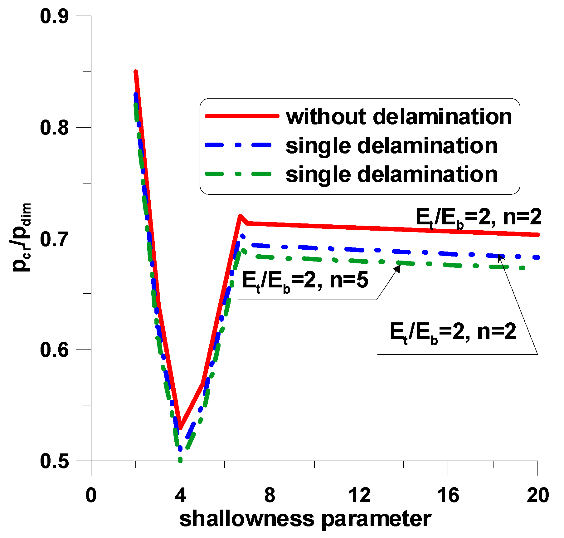
The unsymmetric properties of the FGM structures decrease buckling pressures (Figure 18), since they reduce shell-bending stiffnesses, being the most significant aspect in the evaluation of buckling loads—see Equation (19). The values of buckling pressures (Figure 18) vary with the change of the Et/Eb ratio and of the n coefficient—see Equation (10). The distributions of buckling pressures are similar for both symmetric laminates and unsymmetric configurations of structures made of functionally graded materials. The broader discussion of the results is presented in Ref. [50].

7.2. Compressed Rectangular Plates with a Single Delamination

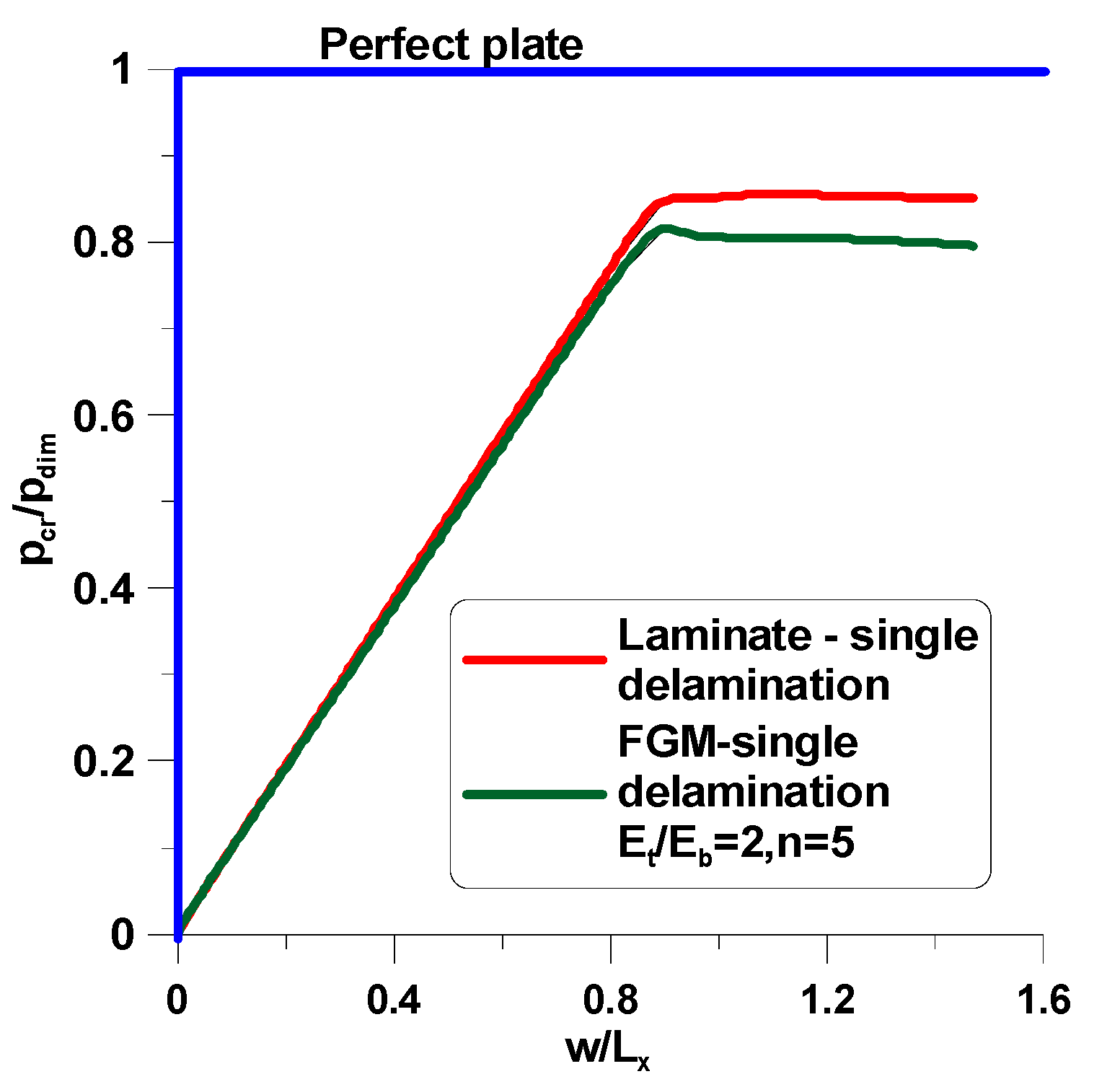
Now, let us consider the buckling problem of compressed plates with delamination with the form plotted in Figure 6. Delamination results in the both pre- and post-buckling behaviour of structures—see Figure 19. For perfect plates without delamination the rapid change between pre- and post-buckling deformations is observed. For structures with delaminations, the initiation and then the development of a delaminated area leads to nonlinear behaviour (Figure 19). Similarly, for spherical shells the effect of unsymmetry of FGM configuration is lower than for composite laminates.
The value pdim corresponds to buckling loads of compressed isotropic (quasi-isotropic) plates and is equal to:
p dim = π 2 E q u a s i 12 ( 1 ν 2 ) h 2 L x 2 ( m L x L y + L y m L x ) 2
where the symbols Lx, Ly denote the length of the plate along the x and y directions.
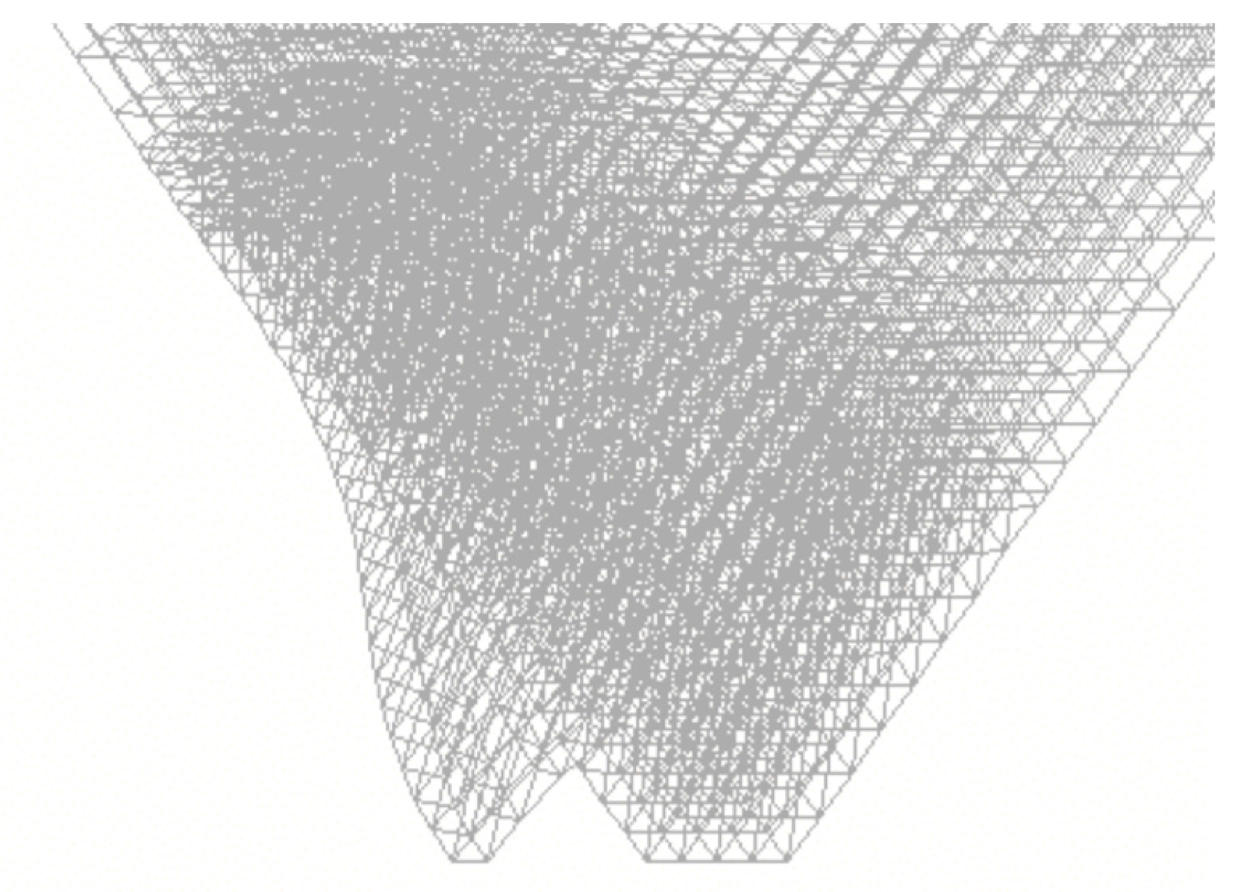
The post-buckling form of the plate is shown in Figure 19 and Figure 20. The elliptical delamination is located at z = h/3. Such a construction of the delamination is assumed to simplify computation and derivation of buckling pressures.

8. Concluding Remarks and Further Recommendations

For laminated composite constructions the detailed information concerning with the theoretical and experimental analysis of delaminated structures can be found in Refs [70,71].
In this section, primary conclusions will be made from reviewing the important results described in previous sections, and the contribution of the present study to the field of mechanics.
Recommendations for further research will also be described.
  • A 2D higher-order method of analysis based on the stretching of the normal to the shell mid-surface is presented herein for obtaining the local buckling loads of structures with unilateral constraints of rectangular plates and axisymmetric spherical shells.
  • Applying the general theory of elasticity with tensor analysis, six field equations, which consist of six displacement relations, have been derived and written.
  • The energy functionals (variational inequalities) in terms of the physical components of the displacements, Hu–Washizu, Hellinger–Reissner, and Lagrange strain energy J, have been derived.
  • Delaminations are represented in the form of geometrical imperfections added to normal displacements. They are characterized by a set of geometrical parameters. The parameters are derived as the lower bound of functions of critical load and the parameter of delaminations.
  • The numerical solutions can be obtained with the use of analytical solutions (the Rayleigh–Ritz method) or FE analysis.
  • The analysis demonstrates that buckling loads with unilateral constraints are reduced for structures made of FGM materials in comparison to laminated structures due to the reduction of bending stiffnesses.
  • With increasing computational capabilities, analysts are gradually becoming more able to deal with three-dimensional problems made of unsymmetrical laminated and FG materials.
  • The presented analysis can be extended for investigations of plated/shell structures with multiple delaminations.
  • The present analysis of buckling characteristics of structures subjected to unilateral constraints shows the necessity of further studies to define the safe lower bounds in the design of laminated and FGM-composed constructions.

Funding

This research received no external funding.

Institutional Review Board Statement

Not available.

Informed Consent Statement

Not available.

Data Availability Statement

Not available.

Conflicts of Interest

The authors declare no conflict of interest.

Nomenclature

Latin Letters
Athe length of the delamination at the ξ1 direction
Athe surface area of the delamination
Aγthe Lame coefficient; γ = 1, 2
Bthe length of the delamination at the ξ2 direction
Dthe length between the edges of spherical shells—Figure 11 and Figure 13
[e]the matrix representation of the strain components εij
Ethe Young modulus of FGMs
Fthe Airy function
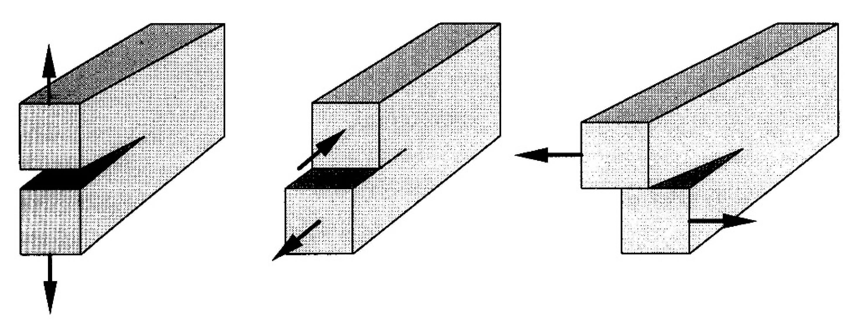
GI, GII, GIIIthe strain energy release rates—see Figure A1
Hthe thickness of the structure
Jthe functional characterizing composite structures as in Equation (6)
Jenthe functional characterizing the strain energy
Jbbcthe functional characterizing the bilateral boundary conditions
Jubcthe functional characterizing the unilateral boundary conditions
KI, KII, KIIIthe stress intensity factors
Lthe length of the plate
ppressure
qparameters describing the shapes of geometrical imperfections—see Figure 14
[Q]the matrix representation of the stiffness matrix
RJthe Rice integral
Rγthe radius of curvature; γ = 1, 2
Rthe radius of the spherical shell
RJthe Rice integral
RBdelthe parameter of the delamination growrh
U ˜ i ( ξ 1 ,   ξ 2 , ξ 3 ) the 3D displacement components; i = 1, 2, 3
ui(ξ1, ξ2)the 2D mid-surface displacement component; i = 1, 2, 3
[u]the matrix representation of the 2D displacement components ui
Vkthe space occupied by the individual k-th layer (or sublaminate)
w(ξ1, ξ2)the 2D normal displacement; it is identical to u3 (ξ1, ξ2)
w*(ξ1, ξ2)the 2D normal displacement of the imperfection (delamination)
Greek Letters
ρthe shallowness parameter (25)
δthe amplitude of the imperfection
ξγthe mid-surface shell curvilinear coordinate; γ = 1, 2
ξ3the normal coordinate to the mid-surface; it is identical to z
φγthe rotation of the normal to the mid-surface about the ξγ axe; γ = 1, 2
χithe parameter characterizing the thickness stretching; i = 1, 2, 3
εijthe 3D strain component; i,j = 1, 2, 3
σijthe 3D stress component; i,j = 1, 2, 3
[σ]the matrix representation of the stress components σij
[σ3]the matrix representation of the transverse shear stress components σi3; i = 1, 2, 3
νthe Poisson ratio of FGMs
ν12, ν21the Poisson ratio of laminates
Subscripts
i, j = 1, 2, 3
γ = 1, 2
delamthe values of delaminated structures
idealthe values of structures without delamination
critthe critical length of the delamination leading to the decrease of buckling pressures
enthe strain energy
bbcthe bilateral (equality) boundary conditions
ubcthe unilateral (inequality) boundary conditions
bthe bottom surface of FGMs
tthe top surface of FGFs
findthe function of the FGMs distribution (11)
nthe power law index
dimdimensionless
quasithe quasiisotropy
Superscripts
nonlmeans nonlinear terms
(k)the number of sublaminates as in Figure (6)—a single delamination; k = 1, 2, 3, 4
Trthe transpose matrix

Appendix A. Mean Stresses and Mechanics of Fracture Criteria

Appendix A.1. Mean Stress Criterion

The experimental results demonstrate evidently that transverse shear stress components σ13, σ23, and σ33 play the fundamental role in the description of the delamination failure process. Referring to the form of failure, the above stress components are usually called the inter-laminar stress components. The stress criterion is usually formulated as follows:
( σ ¯ 13 Z 1 ) 2 + ( σ ¯ 23 Z 2 ) 2 + ( σ ¯ 33 Z 3 ) 2 = 1 ,
where:
σ ¯ i 3 = 1 x a 0 x a σ i 3 d x , i = 1 , 2 , 3
determine the mean of the stress tensor component measured along the length, and Z1, Z2, and Z3 denote the values of allowable stresses in the respective directions. The values of permissible stresses are not high and amount to several dozen MPa.
The criterion (A1) is called the mean stress criterion and was first introduced by Whitney et al. [72]. In the area of delamination, there are singularities of the stress distribution, and FEM solutions demonstrate the increase in the value of stresses along with the density of the mesh. Thus, the determination of the stress distributions at the site of delamination formation does not provide any information about the delamination process. However, if we obtain exact stress distributions in a certain finite area around the singularity, then the criterion (A1) can be used to assess the degree of failure. In this case, however, it is necessary to estimate only by means of a numerical experiment the area characteristic for averaging the values—marked as xα in Formula (A2). Comparing the introduced criterion with the definition of the Rice integral given in Appendix A, direct analogies to the construction of the concept of mean stresses can be noticed. The only difference is in the method of determining which of the stress tensor components are relevant in a given criterion.

Appendix A.2. Mechanics of Fracture

Many researchers take the energy release factor (gap opening work) G as a characteristic parameter for determining the beginning of the process and the development of delamination (both marginal and internal). The fact of occurrence of delamination is determined by the size of the G coefficient, which is defined as the amount of energy required to create a delamination with a unit area. The value of the total G coefficient is defined as the sum of the components from individual delamination (l = 1, 2, …):
G = l = 1 L G l = l = 1 L ( G I + G I I + G I I I ) l
Each of the partial fracture opening works Gl is the sum of three components, defining three typical forms of fracture: I—due to stretching, II—shear in the direction parallel to the area of the fracture, and III—shearing in the direction perpendicular to the area of the fracture—see Figure A1. Theoretical and experimental analysis shows that there are many cases where the partial coefficients are not a sum but some unknown function of the components GI, GII, and GIII, i.e.:
Gl = Gl(GI, GII, GIII)
Figure A1. Fundamental forms of cracks.
Applsci 12 11408 g0a1
Under the linear theory of fracture mechanics, the stress field in the vicinity of the fracture tip is assessed by calculating the stress intensity factor (SIF). These values are also used as a criterion for starting the fatigue crack growth process. The values of the stress intensity factors corresponding to each of the forms of failure are determined from the following relations (Sih et al. [73]):
K I = G I R 11 , K I I = G I I R 22 , K I I I = G I I I R 33 ,
where:
R 11 = τ S 11 , R 22 = τ S 22 , R 33 = τ S 33 , τ = [ S 11 S 22 + S 12 + S 66 / 2 ] S 11 S 22 / 2 ,  
and Sij = [Cij]−1.
The theoretical determination of the G coefficient value is based on the principle of energy conservation, i.e.:
G = ( W e x t W l o s t ) a ,
where Wext is the work done by external forces and Wlost is the deformation energy lost due to fracture elongation from an initial value of a to length a + ∆a. A different definition was proposed by Irwin [74] when investigating the phenomenon of failure of an infinite plate with a slot of length a. If the surface forces described by the s vector are applied to the edges of the slot, the work needed to close the slot is equal to the value of the G coefficient and is expressed by the formula:
G = lim Δ a 0 1 2 Δ a 0 Δ a s Δ U ˜ d a .
Δ U ˜ determines the increment of the displacement vector on the crack surface.
In the case of cracks closed inside the laminate, it very often turns out that the correct size for determining the fracture growth is not its length dimension, but its surface area.
For linearly elastic bodies, the coefficient G is equivalent to Rice’s integral RJ defined as follows:
R J = Γ ( J d y T i U ˜ i , x d s ) ,
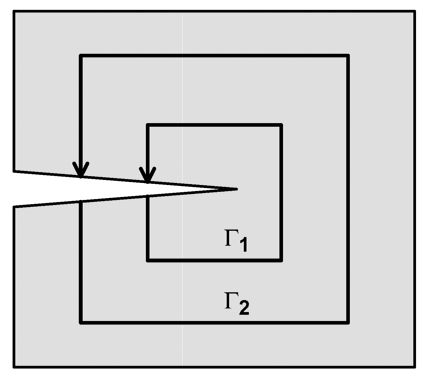
where J (see Equation (A6)) is the strain energy density, T is the force vector normal to the contour Γ, U ˜ the displacement vector, and ds is the contour length element Γ. We assume that the crack growth takes place in the direction of the x axis, and y is the direction perpendicular to x. The definition of Rice’s integral is one of the computational methods for opening the crack.
Numerical calculations are then performed for two (or more) different contours in order to assess the accuracy of the calculations—see Figure A2. Such a comparison was made in the work of Muc et al. [17,75]. The results show very good agreement with the analytical calculations—see Table A1.
Figure A2. Definition of the contour Γ.
Applsci 12 11408 g0a2
Table A1. Comparison of numerical and analytical values of Rice’s integral RJ.
Contour IContour IIAnalytical [76]
0.14374 × 10−40.15189 × 10−40.15122 × 10⁻⁴
The Rice integral concept is used by some authors (cf. Cochelin, Poitier-Ferry [29]) to derive relations for 2D structures such as beams or plates.
The G coefficient values can be determined: (i) analytically or (ii) numerically. In both cases, the starting point for the analysis is the definition in the form of equations (A8) or (A9). The methodology of solving these problems is applied to the problems of beams, plates or shells (2D), plane stress problems (understood as a simplification of 3-W problems) or spatial stress distribution tasks (3D). In numerical calculations, the problem of accuracy of solutions appears due to the peculiarities occurring in the fractures. However, this is not the subject of our considerations.

Appendix A.3. Criterion of Failure and Analysis of the Growth of Delamination

Typically, damage by delamination is associated with the occurrence of the so-called mixed form of destruction, i.e., a combination of types I, II and III—see Figure A1 and the relation (A8). Due to this fact, the following form of the criterion of destruction of composite structures was proposed (cf. Kanninen, Popelar [77]):
( G I G I c ) a + ( G I I G I I c ) b + ( G I I I G I I I c ) c = R B d e l ,
where GIc, GIIc, GIIIc define the critical values of the energy release factors for the first, second and third forms of failure. These values are determined experimentally and it is assumed that they do not depend on the width of the crack. The symbols a, b, c are fitted on the basis of experimental studies, although they are usually assumed to be equal to 1. The influence of their values on the failure curve was investigated in Muc [17,75]. RBdel is the failure index in the event of delamination, and when it is greater than one, delamination develops.
The computational procedure for analyzing the initiation and subsequent development of de-lamination can be represented as follows:
  • Determination of the displacement and stress field at each point on the boundaries of individual layers in the laminate.
  • Assumption of the existence of an inter-layer gap with a given surface area A (length a).
  • Determination of the coefficients of energy release GI, GII, GIII.
  • Calculation of the value of the failure index for the RBdel delamination—Formula (A10):
    • if RBdel < 1 then delamination is not possible;
    • if RBdel = 1, we observe the appearance of delamination at a given point;
    • if RBdel > 1, the development of delamination takes place, and it is necessary to redefine the field of displacements and stresses taking into account the increase in delamination.
It should be emphasized that the study of the development of delamination involves the simultaneous analysis of the possibility of other forms of damage, such as cracking of the first layer in the laminate, fiber damage or buckling. When analyzing the development of delamination in the case of 2D structures, it is necessary to use local wording at the sub-laminate or individual layer level. Moreover, due to the occurrence of local bending effects, both in the description of 2D and 3D, it is necessary to consider the geometrically non-linear theory—see Lee et al. [27], Kutlu, Chang [78], and Muc [36].

References

  1. Bhavar, V.; Kattire, P.; Thakare, S.; Singh, R.K. A review on functionally gradient materials (FGMs) and their applications. IOP Conf Ser Mater. Sci. Eng. 2017, 229, 012021. [Google Scholar] [CrossRef]
  2. Mohammadi, M.; Rajabi, M.; Ghadiri, M. Functionally graded materials (FGMs): A review of classifications, fabrication methods and their applications. Process. Appl. Ceram. 2021, 15, 319–343. [Google Scholar] [CrossRef]
  3. Verma, R.K.; Parnagiha, D.; Chopkar, M. A review on fabrication and characteristics of functionally graded aluminum composites fabricated by centrifugal casting method. SN Appl. Sci. 2021, 3, 1–29. [Google Scholar] [CrossRef]
  4. Miyamoto, Y.; Kaysser, W.A.; Rabin, B.H.; Kawasaki, A.; Ford, R.G. Functionally Graded Materials: Design, Processing, and Applications; Springer: Manhattan, NY, USA, 1999. [Google Scholar]
  5. MitevaMiteva, A.; Bouzekova-Penkova, A. Module for wireless communication in aerospace vehicles. Aerospece Res. Bulg. 2021, 33, 195–209. [Google Scholar] [CrossRef]
  6. Zhou, W.; Shing, A. Preparation and thermodynamic analysis of the porous ZrO2/(ZrO2+Ni) functionally graded bonds. Compos. Part B 2015, 82, 13–22. [Google Scholar] [CrossRef]
  7. Zhou, W.; Zhang, B. Load distribution in threads of porous metal-ceramic functionally graded composite joints subjected to thermomechanical loading. Compos. Struct. 2015, 134, 680–688. [Google Scholar] [CrossRef] [Green Version]
  8. Vinh, P.; Tounsi, A. Free vibration analysis of functionally graded doubly curved nanoshells using nonlocal first order shear deformation theory with variable nonlocal parameters. Thin-Walled Struct. 2022, 174, 109084. [Google Scholar] [CrossRef]
  9. Vinh, P.P.; Chinh, N.V.; Tounsi, A. Static bending and buckling analysis of bi-directional functionally graded porous plates using an improved first order shear deformation theory and FEM. Eur. J Mech./A Solids 2022, 96, 104743. [Google Scholar] [CrossRef]
  10. Muc, A. Non-local approach to free vibrations and buckling problems for cylindrical nano-structures. Comp. Struct. 2020, 250, 112541. [Google Scholar] [CrossRef]
  11. Składanowska, K.; Sanetra, I.; Muc, A. Analysis of fatigue behaviour of composite structures with circular internal delaminations. Compos. Theory Pract. 2017, 17, 121–125. [Google Scholar]
  12. Muc, A.; Kędziora, P.; Krawiec, Z. Damage analysis and monitoring of composite materials and structures under cyclic loads. Proc. Eng. 2011, 10, 1315–1320. [Google Scholar] [CrossRef]
  13. dell’Isola, F.; Della Corte, A.; Battista, A. Generalized Contact Actions. In Encyclopedia of Continuum Mechanics; Altenbach, H., Öchsner, A., Eds.; Springer: Heidelberg, Germany, 2018. [Google Scholar]
  14. Muc, A. Axisymmetric contact problems for composite pressure vessels. J. Compos. Sci. 2022, 6, 143. [Google Scholar] [CrossRef]
  15. Karihaloo, B.L.; Stang, H. Buckling-driven delamination growth in composite laminates: Guidelines for assessing the threat posed by interlaminar matrix delamination. Compos. Part B 2008, 39, 386–395. [Google Scholar] [CrossRef]
  16. Lee, S.Y.; Park, D.Y. Buckling analysis of laminated composite plates containing delaminations using the enhanced assumed strain solid element. Int. J. Solids Struct. 2007, 44, 8006–8027. [Google Scholar] [CrossRef] [Green Version]
  17. Muc, A. Interlaminar failure & buckling of doubly curved shells. Mech. Compos. Mater. 1995, 31, 330–340. [Google Scholar]
  18. Ovesy, H.R.; Kharazi, M. Compressional stability behaviour of composite plates with through-the-width and embedded delaminations by using first order shear deformation theory. Comput. Struct. 2011, 89, 1829–1839. [Google Scholar] [CrossRef]
  19. Pekbey, Y.; Sayman, O. A numerical and experimental investigation of critical buckling load of rectangular laminated composite plates with strip delamination. J. Reinf. Plast. Compos. 2006, 25, 685–697. [Google Scholar] [CrossRef]
  20. Ricci, A.; Gigliotti, M. A novel numerical delamination growth initiation approach for the preliminary design of damage tolerant composite structures. J. Compos. Mater. 2007, 41, 1939–1960. [Google Scholar] [CrossRef]
  21. Ricci, A. (Ed.) Damage Growth in Aerospace Composites; Springer: Berlin/Heidelberg, Germany, 2015. [Google Scholar]
  22. Sekine, H.; Hu, N.; Kouchakzadeh, M.A. Buckling analysis of elliptically delaminated composite laminates with consideration of partial closure of delimitation. J. Compos. Mater. 2000, 34, 551–574. [Google Scholar] [CrossRef]
  23. Davila, C.G.; Johnson, E.R. Analysis of delamination initiation in postbuckled droppedply laminates. AIAA J. 1993, 31, 721–727. [Google Scholar] [CrossRef]
  24. Soni, S.R.; Kim, R.Y. Analysis of suppression of free-edge delamination by introducing adhesive layer. In Proceedings of the the Sixth International Conference on Composite Materials and Second European Conference on Composite Materials, London, UK, 13–18 July 1987; pp. 219–230. [Google Scholar]
  25. Lagace, P.A.; Brewer, J.C. Studies of delamination growth and final failure under tension loading. In Proceedings of the Sixth International Conference on Composite Materials and Second European Conference on Composite Materials, London, UK, 13–18 July 1987; pp. 262–273. [Google Scholar]
  26. Sallam, S.; Smitses, G.J. Delamination buckling and growth of flat cross-ply laminates. Compos. Struct. 1985, 4, 361–381. [Google Scholar] [CrossRef]
  27. Lee, J.; Gürdal, Z.; Griffin, O.H. Layer-wise approach for the bifurcation problem in laminated composites with delaminations. AIAA J. 1993, 31, 331–338. [Google Scholar] [CrossRef]
  28. Chai, H.; Babcock, C.D.; Knauss, W.B. One-dimensional modelling of failure in laminated plates by delamination buckling. Int. J. Solids Struct. 1981, 17, 1069–1083. [Google Scholar] [CrossRef] [Green Version]
  29. Cochelin, B.; Potier-Ferry, M. A numerical model for buckling and growth of delaminations in composite laminates. Comput. Methods Appl. Mech. Eng. 1991, 89, 361–380. [Google Scholar] [CrossRef]
  30. Whitcomb, J.D. Analysis of a laminate with a postbuckled embedded delamination, including contact effects. J. Compos. Mater. 1992, 26, 1523–1535. [Google Scholar] [CrossRef]
  31. Harper, P.W.; Hallett, S.R. A fatigue degradation law for cohesive interface elements—Development and application to composite materials. Int. J. Fatigue 2010, 32, 1774–1787. [Google Scholar] [CrossRef] [Green Version]
  32. Roe, K.L.; Siegmund, T. An irreversible cohesive zone model for interface fatigue crack growth simulation. Eng. Fract. Mech. 2003, 70, 209–232. [Google Scholar] [CrossRef]
  33. Turon, A.; Costa, J.; Camanho, P.P.; Dávila, C.G. Simulation of delamination in composites under high-cycle fatigue. Compos. Part A Appl. Sci. Manuf. 2007, 38, 2270–2282. [Google Scholar] [CrossRef]
  34. Landry, B.; LaPlante, G. Modeling delamination growth in composites under fatigue loadings of varying amplitudes. Compos. Part B Eng. 2012, 43, 533–541. [Google Scholar] [CrossRef]
  35. Muc, A. Design of composite structures under cyclic loads. Comput. Struct. 2000, 76, 211–218. [Google Scholar] [CrossRef]
  36. Muc, A. A fuzzy set approach to interlaminar cracks simulation problems. Int. J. Fatigue 2002, 24, 419–427. [Google Scholar] [CrossRef]
  37. Nikishkov, Y.; Makeev, A.; Seon, G. Progressive fatigue damage simulation method for composites. Int. J. Fatigue 2013, 48, 266–279. [Google Scholar] [CrossRef]
  38. Nilsson, F.; Asp, L.E.; Sjögren, A. On transition of delamination growth behaviour for compression loaded composite panels. Int. J. Solids Struct. 2001, 38, 8407–8440. [Google Scholar] [CrossRef]
  39. Paris, P.C.; Gomez, M.P.; Anderson, W.E. A rational analytic theory of fatigue. Trend Eng. 1961, 13, 9–14. [Google Scholar]
  40. Wu, F.; Yao, W. A fatigue damage model of composite materials. Int. J. Fatigue 2010, 32, 134–138. [Google Scholar] [CrossRef]
  41. Talreja, R.; Varna, J. (Eds.) Modeling Damage, Fatigue and Failure of Composite Materials; Woodhead Publishing is an imprint of Elseviev: Cambridge, UK, 2016. [Google Scholar]
  42. Panagiotopoulos, P.D. Inequality Problems in Mechanics and Applications. Convex and Nonconvex Energy Functions; Birkhauser: Boston, MA, USA, 1985. [Google Scholar]
  43. Muc, A. Theoretical and numerical aspects of contact problems for shells. ZAMP 1984, 35, 890–905. [Google Scholar] [CrossRef]
  44. Studer, C. Numerics of Unilateral Contacts and Friction, Modeling and Numerical Time Integration in Non-Smooth Dynamics, Lecture. In Notes in Applied and Computational Mechanics, v. 47; Springer: Berlin/Heidelberg, Germany, 2009. [Google Scholar]
  45. Cao-Rial, M.T.; Rodríguez-Arós, Á. Asymptotic analysis of unilateral contact problems for linearly elastic cshells: Error estimates in the membrane case. Nonlinear Anal. Real World Appl. 2019, 48, 40–53. [Google Scholar] [CrossRef]
  46. Silveira, R.A.M.; Wellington, L.A.; Pereira, A.P.B. Goncalves Nonlinear analysis of structural elements under unilateral contact constraints by a Ritz type approach. Int. J. Solids Struct. 2008, 45, 2629–2650. [Google Scholar] [CrossRef] [Green Version]
  47. Hartmann, S.; Brunssen, S.; Ramm, E.; Wohlmuth, B. A primal-dual active set strategy for unilateral non-linear dynamic contact problems of thin-walled structures. In Proceedings of the III European Conference on Computational Mechanics Solids, Structures and CoupledProblems in Engineering, Lisbon, Portugal, 5–8 June 2006. [Google Scholar]
  48. Wriggers, P.; Wagner, W.; Stein, E. Algorithms for non-linear contact constraints with application to stability problems of rods and shells. Comput. Mech. 1987, 2, 215–230. [Google Scholar] [CrossRef]
  49. Han, C.-S.; Wriggers, P. On the error indication of shells in unilateral frictionless contact. Comput. Mech. 2002, 28, 169–176. [Google Scholar] [CrossRef]
  50. Muc, A.; Kubis, S.; Bratek, Ł.; Muc-Wierzgoń, M. Higher-Order Theories for the Buckling and Post-buckling Studies of Shallow Spherical Shells made of Functionally Graded Materials. Compos. Struct. 2022, 219, 11501. [Google Scholar] [CrossRef]
  51. Gol’denveizer, A.L. Theory of Elastic Thin Shells; Pergamon Press: Oxford, UK, 1959. [Google Scholar]
  52. Novozhilov, V.V. The Theory of Thin Shells; Noordhoof Ltd.: Groningen, The Netherlands, 1959. [Google Scholar]
  53. Muc, A. Mechanics of Fibrous Composites; Wyd.Akad.: Kraków, Poland, 2003. (In Polish) [Google Scholar]
  54. Akbarov, S.D.; Yahniogliu, N. Delamination buckling of a rectangular orthotropic composite plate containing a band crack. Mech. Compos. Mater. 2010, 46, 721–736. [Google Scholar] [CrossRef]
  55. Karatas, E.E. Buckling delamination of a rectangular thick orthotropic rectangular plates with an embedded rectangular crack subjected to an axial compressive force. Mech. Compos. Mater. 2019, 55, 935–950. [Google Scholar] [CrossRef]
  56. Yusuf Arman, Mehmet Zor, Sami Akham, Determination of critical delamination diameter of compressed composite laminated plates under compressed loads. Compos. Sci. Technol. 2006, 66, 2945–2953. [CrossRef]
  57. Short, G.J.; Guild, F.J.; Pavier, M.J. The effect of the delamination geometry on the compressive failure of composite laminates. Compos. Sci. Technol. 2001, 61, 2075–2086. [Google Scholar]
  58. Kollner, A. Predicting buckling driven delamination propagation in composite laminates: An analytical modeling approach. Compos. Struct. 2021, 266, 113776. [Google Scholar] [CrossRef]
  59. Muc, A. Buckling and post-buckling behaviour of imperfect laminated shallow spherical shells under external pressure. In Composite Structures; Springer: Dordrecht, The Netherlands, 1991; pp. 291–306. [Google Scholar]
  60. Jones, R.M. Mechanics of Composite Materials; Mc Graw-Hill: London, UK, 1975. [Google Scholar]
  61. Gu, H.; Chattopadhay, A. Delamination buckling and post-buckling of composite cylindrical shells. AIAA J. 1996, 34, 1279–1286. [Google Scholar] [CrossRef]
  62. Bazhenov, V.A.; Dinkevich, Y.L. Nonlinear stusdy of deformation and stability of two-layer spherical segments under external pressure with allowance for delaminatiom. Mech. Comp. Mater. 1990, 71–75. [Google Scholar] [CrossRef]
  63. Bolotin, V.V. Damage and failure of composites by delamination. Mech. Compos. Mater. 1987, 23, 424–432. [Google Scholar] [CrossRef]
  64. Bolotin, V.V. Mechanics of delaminations in laminate composite structures. Mech. Comp. Mater. 2001, 37, 387–393. [Google Scholar] [CrossRef]
  65. Kachanov, L.M. Delamination Buckling of Composite Materials; Kluwer Ac. Publ.: Amsterdam, The Netherlands, 1988; pp. 57–87. [Google Scholar]
  66. Kachanov, L.M. Delamination Buckling; Kluwer Ac. Publ.: Amsterdam, The Netherlands, 1988; pp. 19–56. [Google Scholar]
  67. Vorontsov, A.N. Delamination failure of Composite Str. Mech. Compos. Mater. 1989, 17, 723–737. [Google Scholar]
  68. Juhasz, Z. An analytical solution for buckling and vibration of delaminated composite shells. Thin-Walled Struct. 2020, 148, 106563. [Google Scholar] [CrossRef]
  69. Muc, A. Buckling and post-buckling behaviour of laminated shallow spherical shells subjected to external pressure. Int. J. Non-Linear Mech. 1992, 27, 465–476. [Google Scholar] [CrossRef]
  70. Muc, A.; Stawiarski, A. Identification of damages in compositemultilayeredcylindricalpanels with delaminations. Compos. Struct. 2012, 94, 1871–1879. [Google Scholar] [CrossRef]
  71. Muc, A. Description of delaminations in compositemultilayeredstructures - comparison of numerical and experimentalresults for compressedplates. IOP Conf Ser Mater. Sci. Eng. 2020, 744, 012003. [Google Scholar] [CrossRef]
  72. Whitney, J.M.; Nuismer, R.J. Stress fracture criteria for laminated composites containing stress concentrations. J. Compos. Mater. 1974, 8, 253–265. [Google Scholar] [CrossRef]
  73. Sih, G.C.; Paris, P.C.; Irwin, G.R. On cracks in rectilinearly anisitropic bodies. Int. J. Fract. 1965, 1, 189–203. [Google Scholar] [CrossRef]
  74. Irwin, G.R. Fracture in Handbuch der Physik; Springer: Berlin, Germany, 1958; Volume 6, pp. 551–590. [Google Scholar]
  75. Muc, A.; Kędziora, P. A fuzzy set analysis for a fatigue damage response of composite materials. Compos. Struct. 2001, 54, 283–287. [Google Scholar] [CrossRef]
  76. Broek, D. The Practical Use of Fracture Mechanics; Kluwer Academic Publishers: Dordrecht, The Netherlands, 1989. [Google Scholar]
  77. Kanninen, M.F.; Popelar, C.H. Advanced Fracture Mechanics; Oxford Engng. Sc. Series 15; Oxford University Press: Oxford, UK, 1985. [Google Scholar]
  78. Kutlu, Z.; Chang, F.-K. Modeling compression failure of laminated composites containing multiple through-the-width delamination. J. Compos. Mater. 1992, 26, 350–387. [Google Scholar] [CrossRef]
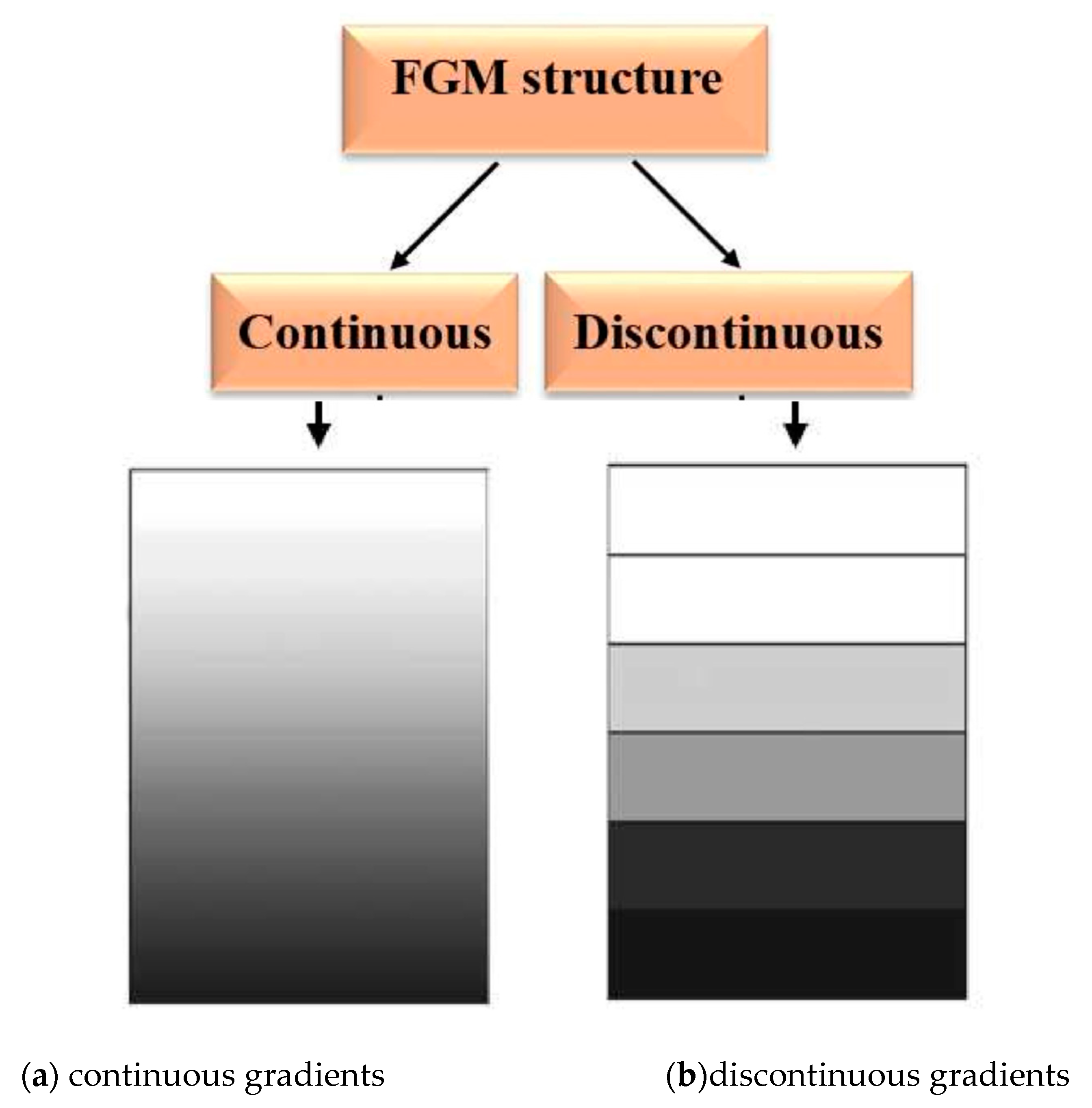
Figure 1. FGM categories.
Applsci 12 11408 g001
Figure 2. A square compressed plate with the embedded circular closed delamination a/Lx = a/Ly = 0.3, h/Lx = 0.012—Ref. [11] (not to scale).
Applsci 12 11408 g002
Figure 3. Buckling of plates (Lx/Ly = 1.0, h/Lx = 0.012) subjected to transverse shear loads for structures without initial delamination—Ref. [12] (not to scale).
Applsci 12 11408 g003
Figure 4. Geometry and location of the embedded delamination.
Applsci 12 11408 g004
Figure 5. Schematic view of delaminated plates (Arman et al. [56]) and of axisymmetric spherical shells (Muc [17]). (a) Local mode, (b) mixed mode, (c) global mode.
Applsci 12 11408 g005
Figure 6. Two-dimensional elliptical delaminations (top view).
Applsci 12 11408 g006
Figure 7. The effects of the delamination length a on the buckling pressures p.
Applsci 12 11408 g007
Figure 8. Single, axisymmetric delamination—the division of the structure into sub-laminates.
Applsci 12 11408 g008
Figure 9. The cross-section of the plate with the delamination a (u(i) = u1(i), w(i) = u3(i), x = ξ1).
Applsci 12 11408 g009
Figure 10. Effects of symmetrical delaminations on buckling loads (h(3)/h(1) = 0.5, the thickness parameter h/Lx = 0.02).
Applsci 12 11408 g010
Figure 11. Cross-section and geometry of spherical shells.
Applsci 12 11408 g011
Figure 12. Forms of the loss of stability of delaminations in spherical shells.
Applsci 12 11408 g012
Figure 13. Geometrical parameters illustrating the imperfect axi-symmetric spherical shallow shells: (a) the convex imperfection in the form of an increased radius polar radius, (b) the concave imperfection characterized by the cosine function.
Applsci 12 11408 g013
Figure 14. Variations of buckling loads for imperfect shallow spherical shells (h/R = 0.01, the shallowness parameter ρ = 5).
Applsci 12 11408 g014
Figure 15. Distributions of the strain energy release rates GI for various shallowness parameter ρ.
Applsci 12 11408 g015
Figure 16. Buckling modes of axi-symmetric spherical shell with a single delamination being the function of the shallowness parameter ρ.
Applsci 12 11408 g016
Figure 17. Distributions of buckling pressures for laminated spherical shells with and without single delamination located at the shell mid-surface.
Applsci 12 11408 g017
Figure 18. Distributions of buckling pressures for spherical shells made of FGMs with and without single delamination located at the shell mid-surface.
Applsci 12 11408 g018
Figure 19. Pre- and post-buckling deformations of compressed plates with delaminations (w is a normal deflection at the middle of the plate).
Applsci 12 11408 g019
Figure 20. Post-buckling form of compressed simply supported rectangular plate with single elliptical delamination.
Applsci 12 11408 g020
Table 1. Mechanical properties.
Unidirectional Composites—See Jones [60]FGMs—See Equations (10) and (11)
E1/E2 = E1/E3 = 20,
E1/G13 = 34,
E1/G23 = 20
ν12 = 0.28Et/Eb = 5ν = 0.3
Here, 1 corresponds to the direction parallel to fibres. n = 0 in Equation (11) characterizes isotropic (quasi-isotropic) properties.
Publisher’s Note: MDPI stays neutral with regard to jurisdictional claims in published maps and institutional affiliations.