Article

Experimental Study on the Permeability of Rare Earths with Different Particle Composition for a Novel Heap Leaching Technology

1
School of Infrastructure Engineering, Nanchang University, Nanchang 330031, China
2
Jiangxi Hydraulic Safety Engineering Technology Research Center, Jiangxi Academy of Water Science and Engineering, Nanchang 330029, China
*
Author to whom correspondence should be addressed.
Appl. Sci. 2022, 12(22), 11368; https://doi.org/10.3390/app122211368
Submission received: 12 October 2022 / Revised: 7 November 2022 / Accepted: 7 November 2022 / Published: 9 November 2022

Abstract

:
In order to solve the problem of vegetation restoration in the traditional heap leaching of rare earths, a novel heap leaching technology is proposed. In the novel technology, leaching liquid is laterally injected into the rare earth pile from the side end so that vegetation restoration can be carried out quickly on the top of the pile. In this study, a laboratory test was performed to investigate the permeability of the ion-adsorbed rare earth pile under lateral liquid injection conditions. Four rare earth samples with varied combinations of the mineral particles at different sizes were adopted in the test to emphatically discuss the influence of the particle composition on permeability. The experimental results show that the permeability of the rare earth pile under the lateral liquid injection conditions is governed by the migration of fine particles. As the hydraulic head of the leaching liquid increases, the fine particles undergo a motion process of stabilization, migration initiation, deposition, and remigration. Accordingly, the permeability coefficient of the rare earth pile exhibits a variation of stabilization, a gradual increase, a re-stabilization, and a re-increase. The fine particle migration and exudation causes the permeability of the rare earth pile to be non-uniform in space. The permeability coefficients near the liquid injection end and the liquid outlet end are much greater than those are at the middle positions of the pile. The particle composition of the rare earth has an important effect on the permeability of the pile. In the rare earth with a combination of coarse and fine particles, preferential flow paths are easy to develop as in this soil, the fine particles easily migrate and they cannot block the pore channels. By contrast, the fine particles find it difficult to migrate, and the permeability coefficient is relatively stable in the fine-medium particle rare earth. This particle composition is conducive to the heap leaching of the rare earth under lateral liquid injection conditions.

1. Introduction

Rare earth resources in China are abundant and complete in their variety. Among them, the ion-absorbed rare earth that is rich in medium and heavy rare earth elements is widely explored in Jiangxi Province, China [1]. At present, the leaching methods that extract ion-absorbed rare earth elements from mines mainly include in situ leaching and heap leaching [2,3]. In, in situ leaching, it is difficult to fully explore or predict the discontinuities and inhomogeneities of the mineral deposits. It often leads to the unforeseen loss of leaching liquid, resulting in serious environmental pollution and resource waste [4]. Compared to in situ leaching, heap leaching is a more controllable method, and can effectively reduce the environmental pollution and resource waste. In addition, heap leaching is more efficient in the extraction rate for different grades of rare earth [5]. However, in the traditional heap leaching, the leaching liquid is injected into the rare earth pile from its top. This poses a huge challenge for quickly carrying out vegetation restoration on the top of the pile as the top is covered with leaching liquid for a long time [6]. Therefore, in order to realize the efficient and green development of ion-absorbed rare earth resources, it is necessary to develop an integrated technology of rare earth leaching and vegetation restoration.
In this regard, we proposed a novel heap leaching technology that is suitable for vegetation restoration [7], as shown in Figure 1. In the novel heap leaching technology, a heap leaching site needs to be built against a natural mountain, in which a vertical impermeable bedrock is required at the starting end of the heap. A vertical concrete wall can be manually built to replace the vertical bedrock in the absence of one. In addition, the heap leaching site should be relatively flat. The rare earth ore is stacked horizontally level by level, and the leaching liquid is laterally injected into the pile from the side end. After the leaching of the current level pile is completed, the stacking and leaching of the next level pile begins. Meanwhile, the vegetation restoration can be carried out synchronously on the top of the current level pile, where it is not covered by the leaching liquid. The novel heap leaching technology that is characterized by the lateral liquid injection leaves space for the vegetation restoration on the top of the pile. In this way, rare earth leaching and vegetation restoration can be synchronized so as to reduce the environmental damage that is caused by the rare earth leaching.
For the traditional heap leaching technology and the novel heap leaching technology, the seepage of the leaching liquid in the piles can be numerically simulated by the software COMSOL, as shown in Figure 2. With regard to the traditional heap leaching, the leaching area on the cross section can reach 91.3% of the total area. The ratio is 88.5% for the novel heap leaching technology. Although the leaching efficiency of the novel heap leaching technology is slightly lower, it is more environmentally friendly. It not only meets the vegetation restoration requirements on the top of the pile, but also reduces resources waste of rare earth elements through controlling the permeability. Therefore, the novel heap leaching technology provides a promising approach to solve the major issues that hinder the healthy development of the rare earth industry such as high environmental pollution and low leaching efficiency [8,9].
It is well known that during the heap leaching of rare earth, the leaching efficiency and pile stability are highly dependent on the seepage characteristics of leaching liquid in the rare earth pile. For the zones with lower permeability, it is easy to control the leaching liquid so that it stays in front of these zones, resulting in the insufficient leaching of these zones [10]. While in the zones with higher permeability, an excessive seepage force probably causes fine mineral particles to migrate to other places, thereby forming large pore structures and preferential flow paths. This would result in insufficient leaching of the zones that are far away from the preferential flow paths [11,12]. More importantly, the preferential flow paths may cause the local collapse and instability of the rare earth pile. McBride et al. [13] numerically investigated the preferential flow behavior in unsaturated packed beds. They found that the nonuniform and adverse flow due to the preferential flow paths reduced the ore-liquid contact, and hence, this led to lower metal recoveries. Kukemilks et al. [14] and Zhang et al. [15] investigated the influence of preferential flow on hillslope stability. They suggested that a local-scale increase of the pore-water pressure due to the preferential flow reduced the slope stability. Therefore, it is of great significance to study the permeability of the ion-adsorbed rare earth pile under lateral liquid injection conditions for the efficient leaching and pile stability control of the novel heap leaching technology.
Some experimental studies have been carried out in an attempt to reveal the permeability of rare earth in, in situ leaching or in traditional heap leaching. Wang et al. [16] investigated the pore structure evolution of rare earth ore samples after the injection of ammonium sulfate solution by means of nuclear magnetic resonance (NMR) and scanning electron microscopy (SEM). It was found that the adsorption and desorption of bulk clay microparticles caused dynamic changes in the pore structure, resulting in a fluctuation of the permeability coefficient. Xie et al. [17] studied the influence mechanism of the leaching solution on the pores of ion-absorbed rare earth ore by a column leaching experiment. The results show that the fine particle migration that was caused by the flow of leaching solution is the main reason for the change of the ore body permeability. Liu et al. [18] performed column leaching experiments to study the influences of particle size distribution and particle migration on the permeability coefficient of rare earth ore in the process of in situ leaching. They found that during the leaching, the content of the fine particles that were smaller than 0.075 mm decreased most significantly. When the proportion of the fine particles that were smaller than 0.075 mm was less than 30%, the migration of the fine particles and the permeability coefficient gradually declined during the leaching process. Wang et al. [19] demonstrated that it was the ion exchange that caused the fine particle migration and recombination during the leaching. He et al. [20] and Chen et al. [21] studied the effects of the concentration and the pH of the leaching liquid on the seepage characteristics of the rare earth, and they suggested that ammonium sulfate with a concentration of 0.2 mol/L and a pH of 4–8 was optimal for high permeability. Zhang et al. [22] investigated the effects of salt on the swelling and permeability of clay minerals, and the results showed that adding salt solution could inhibit the swelling and permeability processes. In addition, Yin et al. [23] experimentally studied the permeability of ion-absorbed rare earth under various particle gradations. They deemed that the rare earth particles with smaller void ratios had a greater viscosity to the flow of the leaching liquid, and the permeability increased significantly with an increase in the void ratio. In an experiment of extracting rare earth elements from new sources such as bauxite residue and silicate-based ore, the acid leaching generated silica gels, thereby reducing the extraction rate. Botelho Junior et al. [24] demonstrated that its synthesis could be avoided using hydrogen peroxide. In addition, Botelho Junior et al. [25] compared the effects of the direct leaching and the acid baking process on the extraction of rare earth elements from the silicate-based ore. For the baking experiments, the results were better than the direct leaching ones were for the rare earth elements, by over 85%. The solid–liquid ratio had almost no effect on the extraction of the rare earth elements.
However, the current experimental research on the permeability of rare earths mainly focuses on vertical liquid injection conditions. There are few studies which have reported on the permeability of rare earths under lateral liquid injection conditions. Therefore, the previous experimental studies are incapable of guiding the design of the novel heap leaching structure. Furthermore, when the rare earth ores are leached with the heap leaching method, the ore particles with different sizes may be separated and recombined during the stacking process due to the segregation effects. The particle gradation of the rare earth ores after stacking is not exactly the same as that in situ. It has been demonstrated that the particle gradation has an important effect on the permeability of rare earth ores [26]. Therefore, in this study, the permeability of the ion-absorbed rare earth with various particle gradations under lateral liquid injection conditions is investigated by laboratory tests in an attempt to provide a reference for the efficient leaching and stability control of the novel heap leaching technology.
The paper is organized as follows: Section 2 introduces the model test procedure for the heap leaching of the ion-absorbed rare earth under lateral liquid injection conditions, which includes information about the test devices, the rare earth samples, and the test methods. Section 3 presents the test results, and the effects of the particle composition on the permeability of the rare earth pile under the lateral liquid injection conditions are discussed. Section 4 focuses on discussing the particle gradation change after the leaching. Section 5 concludes and summarizes the manuscript.

2. Model Test of Heap Leaching under Lateral Liquid Injection

2.1. Test Device

A self-designed and manufactured device was utilized to carry out the model test of the rare earth heap leaching under the lateral liquid injection conditions. The test device consisted of a model tank, a liquid injection device and a data acquisition system, as shown in Figure 3. The model tank was made of transparent acrylic sheets, and it was divided into three zones by using porous plates with a pore diameter of 0.4 cm. The left zone is a buffer zone, in which glass marbles were placed to provide a buffering effect for the leaching liquid to flow into the rare earth pile. A liquid inlet with a diameter of 0.8 cm was set at the left end of the buffer zone. At its top, an exhaust valve was installed to discharge the air within the buffer tank when the buffer tank was not fully filled with the leaching liquid. Once the buffer tank was completely filled, the exhaust valve was closed. The middle zone of the model tank was used for stacking the rare earth samples. This zone has a length of 25 cm, a width of 10 cm, and a height of 15 cm. In the real heap leaching of rare earths, the bottom of the pile would be inclined with a slope of 1–3% so that the leaching liquid can be drained freely from the bottom. In order to reproduce the reality, the bottom of the middle zone was set to be sloping with a gradient of 2%. On the side of the middle zone, four circular holes with intervals of 5 cm were reserved for connecting the sensors that are placed within the rare earth pile and the data acquisition instrument outside the model tank. The right zone of the model tank is a collection tank that was used to collect the exuded leaching liquid and mineral particles. The liquid injection device was composed of a support frame and a liquid supply box with a valve. The liquid supply box was connected with the model tank through a rubber tube. The data acquisition system contained pore water pressure sensors, a data acquisition instrument, and a computer. In the tests, the ammonium sulfate solution with a concentration of 2% was used as the leaching liquid. The distance from the model tank bottom to the free surface of the leaching liquid in the liquid supply box is defined as the hydraulic head of the leaching liquid, which is denoted by the symbol H.

2.2. Preparation of Rare Earth Samples

The soil samples for testing were taken from the Lingbei ion-absorbed rare earth mine in Dingnan County, Jiangxi Province, China. The main minerals in the soil samples were kaolin clay (15–40%), quartz (40–45%), potassium feldspar (10–25%), and mica (5%). The chemical composition of the minerals were mainly composed of SiO2 (67–78%) and Al2O3 (5–19%). The other chemical concentrations were K2O (0.3–6%), which was followed by Na2O (0.1–5%) and Fe2O3 (0.7–2.5%). In particular, the contents of Fe3O4, MgO, CaO, Na2O, and K2O were lower, accounting for only 8% of the total.
The ion-absorbed rare earth was first dried, and then, it was screened and divided into seven groups according to the particle size: particles that were smaller than 0.15 mm, particles that were within 0.15–0.25 mm, particles that were within 0.25–0.60 mm, particles within that were 0.60–1.18 mm, particles that were within 1.18–2.35 mm, particles that were within 2.35–5.00 mm, and particles that were larger than 5 mm. To facilitate their expression, the particles that were smaller than 0.25 mm were classified as fine particles, the particles that were within 0.25–2.35 mm were classified as medium particles, and the particles that were larger than 2.35 mm were classified as coarse particles. Based on the seven groups of particles, the rare earth samples for testing were configured, as shown in Figure 4. The rare earth sample that has the same particle gradation as the in situ rare earth is called the standard soil sample S1. The fine particles and medium particles were combined and configured as the soil sample S2. The combination of the medium particles and coarse particles is the soil sample S3, and the combination of the coarse particles and fine particles is soil sample S4. The mass percentages of each particle grade for the four soil samples are listed in Table 1.

2.3. Test Method

The configured rare earth samples were filled uniformly in the middle zone of the model tank layer by layer. Each layer had a height of 2 cm. In order to avoid the interfaces between the layers during the filling, planing was carried out between the adjacent layers. During the tests, the hydraulic head H first remained at a constant smaller value. After the rare earth samples were completely saturated, the hydraulic head H was increased gradually, and the variations of the pore water pressure and seepage flow with H were observed and recorded. Four monitoring points A–D were chosen for the observation and recording, as shown in Figure 5. The four monitoring points were located at the same elevation, 7.5 cm away from the top of the rare earth pile. The interval between the adjacent observation points was 5 cm, and the observation points at both ends were also 5 cm away from the ends of the pile. The pore water pressure at the observation points was collected every 1 min by the data acquisition system. When the collected data for five consecutive timepoints remained almost the same, it was considered that the seepage inside the rare earth pile reached a stable state under the current hydraulic head. Then, the pore water pressure and seepage flow at this time were recorded for the current hydraulic head of the leaching liquid. Subsequently, the hydraulic head was increased by 2 cm, and the testing procedures that are described above were repeated until the seepage flow increased significantly and a large amount of mud seeped out. Finally, the exuded mud was settled, dried, and weighed. The standard soil sample S1, the fine-medium particle soil sample S2, the medium-coarse particle soil sample S3, and the coarse-fine particle soil sample S4 were tested in sequence.

3. Permeability of the Rare Earth Pile under Lateral Liquid Injection

3.1. Variation of the Permeability Coefficient with Hydraulic Head

According to Darcy’s law, the permeability coefficient of the rare earth pile in the model tests was determined by:
K = Q L / A Δ h
where K denotes the permeability coefficient, Q denotes the seepage flow, L is the distance between the adjacent observation points, A denotes the cross-sectional area, and Δh denotes the difference of the hydraulic head between the adjacent observation points.
The permeability coefficients between the adjacent observation points of the rare earth pile are expressed as KAB, KBC, and KCD, respectively. The variations of these permeability coefficients with the increasing hydraulic head for the four soil samples are shown in Figure 6. With an increase in the hydraulic head of leaching liquid, the permeability coefficients show a trend of increase on the whole, and especially, the permeability coefficient KAB near the liquid injection end varies most significantly. The variation of KAB with the hydraulic head is clearly divided into four stages. In the first stage, namely, the curve e–f in Figure 6, the permeability coefficient is small and remains almost constant. This indicates that the seepage of the leaching liquid within the rare earth pile is in a stable state when the hydraulic head is small. In the second stage (see the curve f–g), the permeability coefficient increases slowly with the hydraulic head. This is because as the hydraulic head increases, the fine particles start to move in the pores of the soil samples due to the increasing seepage force. This enhances the connectivity between the pores, and accordingly, the permeability is increased. This stage is also the startup stage of the fine particle migration. In the third stage (see the curve g–h), the permeability coefficient tends to stabilize again. In the process of increasing the hydraulic head, more and more particles with various sizes participate in the migration. The co-migration of the particles of different sizes can easily cause the blockage of the pores, thereby preventing the connectivity of the pores and the increase of the permeability in the rare earth pile. In the fourth stage (see the curve h–i), the permeability coefficient increases substantially. This is because when the hydraulic head of leaching liquid is increased to a certain level, the particles that block the pores are driven to migrate again by the greater seepage force, and the connectivity of the pores is further increased. This stage is the development stage of preferential flow paths.
For the coarse-fine particle soil sample S4, the particle size varies widely between the coarse particles and the fine particles. The fine particles are not large enough to block the pores between the coarse particles during the migration. Once the migration of the fine particles is initiated, the permeability coefficient increases continuously. Therefore, the variations of the permeability coefficients for the soil sample S4 have no secondary stable stage, i.e., the stage of the curve g–h. Furthermore, the hydraulic head corresponding to the fine particle migration initiation for the soil sample S4 is the smallest among the four soil samples. This indicates that under the lateral liquid injection conditions, the absence of medium particles makes it easier for the fine particles to migrate and they cannot block the pore channels. In this case, it is easy to form preferential flow paths for the leaching liquid. In our previous publication [7], we have experimentally and numerically studied the formation of the preferential flow paths and its influences on the leaching efficiency of the rare earth under lateral liquid injection conditions. It is found that the preferential flow paths mainly develop in the lower part of the rare earth pile. This causes the leaching liquid to flow intensively to the lower part of the pile, and this results in a blind zone of leaching at the top of the pile, thereby reducing the leaching rate of the entire pile. With regard to the fine-medium particle soil sample S2, the permeability coefficients at different observation locations change relatively slowly with the increasing hydraulic head. This means that in the fine-medium particle soil sample, the degree of the fine particle migration is lower. During the heap leaching of rare earths, the stable permeation is conducive to the leaching of rare earth ions [27].
For the soil samples S1, S2, and S3, the permeability coefficient between the observation points B and C, namely KBC, grows the least with the increase of the hydraulic head H. This is because the fine particles migrated from the liquid injection end to settle down in the BC section, thus hindering the formation of connected pores at this location. In addition, the adsorption of the leaching liquid ions on the surfaces of the deposited fine particles will form an electric double layer. The action of the electric double layer reduces the cross-sectional area of the leaching liquid flow between the pores, which further hinders the seepage of the leaching liquid [28]. With regard to the coarse-fine particle soil sample S4, the fine particles are also deposited during the leaching process. However, the deposition state is difficult to maintain in the pore structure that uses the coarse particles as the skeleton. Consequently, when the hydraulic head is increased from 24 to 26 cm, the permeability coefficient KBC of the soil sample S4 increases suddenly.
Compared with the permeability coefficient KBC, the permeability coefficient KCD between the observation points C and D varies more significantly with the increasing hydraulic head H. This is because the observation section at CD is close to the liquid outlet end, and the exudation of the fine particles from the liquid outlet end leads to an increase in the pore connectivity and the permeability coefficient. In comparison with the standard soil sample S1 and the fine-medium particle soil sample S2, the gap between the particles is larger and the pore connectivity is better for the medium-coarse particle soil sample S3. Therefore, the permeability coefficient KCD of the soil sample S3 changes more significantly with the increase of the hydraulic head.
Figure 7 presents the permeability coefficients at different locations under the hydraulic head H = 30 cm for the soil samples S1, S2, and S3. It is clearly seen that under the lateral liquid injection conditions, the permeability coefficient of the rare earth pile exhibits a non-uniform distribution in space. Specifically, the permeability coefficients at both ends are greater than those in the middle part of the pile. For the standard soil sample S1, the permeability coefficient at the liquid injection end is greater by 89.3% than that at the middle location. The relative differences are 74.6% and 89.2%, respectively, for the fine-medium particle soil sample S2 and the medium-coarse particle soil sample S3. The spatial distribution of the permeability is more inhomogeneous for the standard soil sample S1 and the medium-coarse particle soil sample S3.

3.2. Variation of the Leachate with Hydraulic Head

During the tests, when the hydraulic head of leaching liquid reaches a certain level, the leachate that is exuded from the outlet end becomes turbid, especially for the coarse-fine particle soil sample S4, as shown in Figure 8. After the leaching test of each soil sample was completed, the leachate was left for the sediment. Then, the mineral particles were separated from the mixed leachate and dried for a particle gradation analysis. Figure 9 gives the gradation curves of the exuded rare earth particles for the four testing soil samples. For the standard soil sample S1, the coarse particles that were larger than 2.35 mm do not exude during the leaching. The exuded mineral particles were mainly the fine particles that were smaller than 0.15 mm, whose weight accounts for 64.7% of the total weight of the exuded particles. With regard to the fine-medium particle soil sample S2, the exuded particles were all of the fine particles that were smaller than 0.15 mm. When the medium-coarse particle soil sample S3 was tested, the exudates were mainly the medium particles with sizes of 0.25–0.60 mm, and their mass accounted for 57.1% of the total. Actually, these are also the finer particle components in this soil sample. Among the exuded particles of the coarse-fine particle soil sample S4, the fine particles that were smaller than 0.15 mm accounted for 78.8% of the weight. The proportion of the coarse particles is larger than 2.35 mm, they account for only 8.8% of the total. Clearly, for any of the four soil samples, the exuded rare earth particles during the leaching tests are mainly the finer particle components of the soil samples.
The rare earth particle exudation from the outlet end is clearly adverse to the pile stability, and furthermore, the faster the particles exude, then the worse the pile stability is. Figure 10 shows the variations of the particle exudation rate with the increasing hydraulic head for the four soil samples. The hydraulic head at which the rare earth particles begin to exude is defined as the critical hydraulic head of particle exudation Hc. It is seen from Figure 10 that the relationship of the critical hydraulic head between the four soil samples is Hc(S4) < Hc(S2) = Hc(S1) < Hc(S3). For the soil sample S4, because the sizes of the fine and coarse particles vary widely, the fine particles easily migrate within the pores between the coarse particles and exude from the rare earth pile. Therefore, it is critical that the hydraulic head of particle exudation is the smallest among the four soil samples. In the medium-coarse particle soil sample S3, driving the medium particles to exude from the outlet end requires a greater seepage force. Hence, the critical hydraulic head of particle exudation in this soil sample is the highest. In the soil sample S2 that lacks coarse particles, its critical hydraulic head of particle exudation is 32 cm, and it is the same as that in the standard soil sample S1. This means that the coarse particles have little constraint on the migration of the fine particles, and the medium particles play a major role in the constraint of this. In comparison with the soil samples S1 and S4, the soil samples S2 and S3 have a relatively gentle change in the particle exudation rate as the hydraulic head increases. It is consistent with the gentle variation of the permeability coefficient KCD in the soil samples S2 and S3. This shows in the fine-medium particle soil sample S2 and the medium-coarse particle soil sample S3, the particle migration degree near the outlet end is lower.
The liquid composition of the exudates was measured by volume to analyze the seepage flow of the rare earth pile under the lateral liquid injection conditions. Figure 11 shows the seepage flow through the outlet end under various hydraulic heads for the four testing soil samples. It is seen that when the hydraulic head of leaching liquid is lower than 22 cm, the seepage flow is small and relatively stable. Then, the seepage flow increases slowly, stabilizes again, and finally, it increases again. This process is consistent with the variation of the permeability coefficient that was described earlier, and it is related to the fine particle migration, pore blockage, and particle remigration. For the standard soil sample S1, the seepage flow increases suddenly at the hydraulic head H = 32 cm. With regard to the coarse-fine particle soil sample S4, the seepage flow surge occurs at H = 26 cm. In comparison, the seepage flow increases in the fine-medium particle soil sample S2 and the medium-coarse particle soil sample S3 are much more moderate. This indicates that the increase in the content of the medium particles can have a buffer effect on the seepage. On the one hand, it prevents a large number of fine particles from migrating when the hydraulic head is small, which occurs in the coarse-fine particle soil sample S4. On the other hand, it alleviates the remigration of those fine particles that are blocking the pores when the hydraulic head is greater, which occurs in the standard soil sample S1. Overall, the seepage flow variation in the fine-medium particle soil sample S2 is the smoothest among the four soil samples. This demonstrates again that the combination of fine and medium mineral particles is conducive to the heap leaching of rare earths under lateral liquid injection conditions.

4. Particle Gradation Change after Leaching

When the leaching of each rare earth sample was completed, a quantity of rare earth particles around the observation points A–D was taken out from the model tank by using a ring knife. After drying these particles, screen tests were carried out to acquire the particle gradation of the rare earth after the leaching. Through comparing the particle masses before and after the leaching, the rate of the mass change for each particle grade can be obtained as follows:
η = M a M b M b × 100 %
where η denotes the change rate of the particle mass, Ma is the particle mass after leaching, and Mb is the particle mass before leaching.
Figure 12 shows the change rate of the particle mass for each particle grade in the four soil samples. It is clearly seen that after the leaching, the mass of each particle grade changed at different degrees at various observation points. This indicates that the migration of rare earth particles occurs in the entire pile during the leaching. In the standard soil sample S1 (see Figure 12a), the mass change rate of the fine particles that were smaller than 0.15 mm increases monotonically from the observation point A to the observation point D. This means that under the lateral liquid injection conditions, the fine particles migrated from the liquid injection end to the liquid outlet end, and eventually, they settled down near the outlet end. Notably, in the vicinity of the liquid injection end, when the fine particles migrated out, there were no fine particles to replenish it. As a result, the soil near the liquid injection end was dominated by coarse and medium particles. This is also the reason why the permeability coefficient near the liquid injection end KAB is greater than that at other locations.
Among the four soil samples, the change rate of the particle mass for the fine-medium particle soil sample S2 is the smallest (see Figure 12b). This shows that in this soil sample, the gap between the rare earth particles is smaller, and the fine particles cannot migrate as easily. It corresponds to the slower change of the permeability coefficient in the soil sample S2, as described in Figure 6. In comparison, the particle mass of the medium-coarse particle soil sample S3 changed significantly before and after the leaching (see Figure 12c). Similar to the soil sample S1, the mass change rate of the medium particles within 0.25–0.60 mm increases monotonically from the liquid injection end to the liquid outlet end. It is demonstrated that in this soil sample, the medium particles (also the finer particle component) easily migrate under the lateral liquid injection conditions due to the larger gap between the particles. Consequently, the permeability coefficient in the soil sample S3 is more sensitive to the increasing hydraulic head of the leaching liquid than that in the soil sample S2.
For the coarse-fine particle soil sample S4 (see Figure 12d), the relative change of the fine particle mass after the leaching was not significant, although its permeability coefficient varied most noticeably among the four soil samples. This because the soil sample S4 has the largest mass of fine particles before the leaching. Unlike the other soil samples, in the soil sample S4, the mass change rate of the fine particles that were smaller than 0.15 mm first increases from the point A to the point C, and then, it decreases from the point C to the point D. This is because in this soil sample, a large number of fine particles exude from the outlet end during the leaching (see Figure 10), resulting in a slump in the fine particle content near the outlet end. From the above analysis, it can be seen that the particle gradation change after the leaching can adequately explain the permeability variation of the rare earth pile during the lateral liquid injection. It is demonstrated that the permeability of the rare earth pile is governed by the migration of fine particles. In the fine-medium particle soil, the fine particles find it difficult to migrate, and the permeability coefficient is relatively stable, which is conducive to the leaching of rare earth ions.
In this study, the focus is on the permeability of the rare earth pile under lateral liquid injection conditions. The relationship between the permeability and the leaching of rare earth elements is beyond the scope of this paper, and it is not considered in this study. Notwithstanding its limitations, it can still provide guidance for the implementation of the novel heap leaching technology.

5. Conclusions

In this paper, in order to provide a foundation for the novel heap leaching technology that is suitable for vegetation restoration, the permeability of the ion-adsorbed rare earth under the lateral liquid injection conditions was investigated by running a model test. The influence of the mineral particle composition on the permeability was highlighted. According to the above research, the main conclusions were obtained as follows:
(1)
Under lateral liquid injection conditions, the permeability of the ion-adsorbed rare earth pile is governed by the migration of fine mineral particles. As the hydraulic head of leaching liquid increases, the motion of the fine particles is divided into four stages, stabilization, migration initiation, deposition, and remigration. Accordingly, the permeability coefficient exhibits a varying process of stabilization, gradual increase, re-stabilization, and re-increase.
(2)
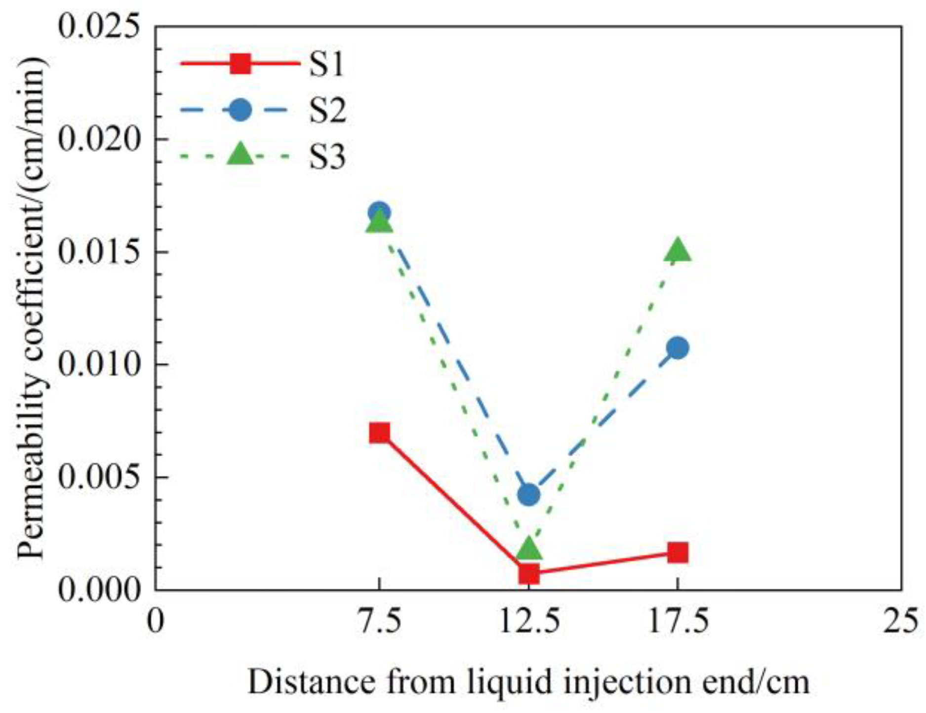
The permeability of the rare earth pile under the lateral liquid injection conditions is non-uniform in space. The permeability coefficients near the liquid injection end and the liquid outlet end are significantly larger than those at the middle positions of the pile. This non-uniformity is caused by the fine particle migration without replenishment near the liquid injection end and the fine particle exudation from the liquid outlet end.
(3)
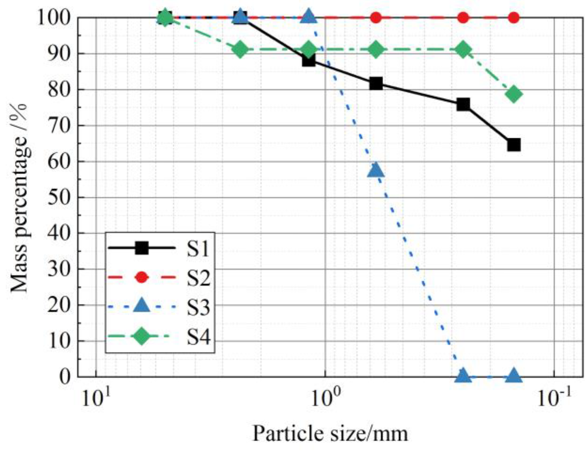
The particle composition of the rare earth has an important effect on the permeability of the rare earth pile under the lateral liquid injection conditions. For the coarse-fine particle soil, the fine particles easily migrate, and they cannot easily block the pore channels. In this case, preferential flow paths are likely to develop in the lower part of the rare earth pile, resulting in a blind zone of leaching at the top of the pile. For the fine-medium particle soil, the fine particles cannot easily within the pore channels and thereby, the permeability coefficient is relatively stable. This particle composition is conducive to the heap leaching of the rare earth under lateral liquid injection conditions.

Author Contributions

Conceptualization, W.J.; methodology, W.J. and J.Y.; investigation, W.J. and J.Y.; validation, J.Y.; formal analysis, W.J. and J.Y.; data curation, W.J.; writing—original draft preparation, W.J.; writing—review and editing, J.Y., C.Y. and X.Z.; visualization, W.J.; supervision, Z.Y.; project administration, D.L.; funding acquisition, J.Y., C.Y. and X.Z. All authors have read and agreed to the published version of the manuscript.

Funding

This research was funded by the National Key Research and Development Program of China (2019YFC0605005 and 2019YFC0605001) and the National Natural Science Foundation of China (52179102 and 51969015).

Institutional Review Board Statement

Not applicable.

Informed Consent Statement

Not applicable.

Data Availability Statement

Not applicable.

Conflicts of Interest

The authors declare no conflict of interest.

References

  1. Dutta, T.; Kim, K.H.; Uchimiya, M.; Kwon, E.E.; Jeon, B.H.; Deep, A.; Yun, S.T. Global demand for rare earth resources and strategies for green mining. Environ. Res. 2016, 150, 182–190. [Google Scholar] [CrossRef] [PubMed]
  2. Huang, X.W.; Long, Z.Q.; Wang, L.S.; Feng, Z.Y. Technology development for rare earth cleaner hydrometallurgy in China. Rare Met. 2015, 34, 215–222. [Google Scholar] [CrossRef]
  3. Ilankoon, I.M.S.K.; Tang, Y.; Ghorbani, Y.; Northey, S.; Yellishetty, M.; Deng, X.; McBride, D. The current state and future directions of percolation leaching in the Chinese mining industry: Challenges and opportunities. Miner. Eng. 2018, 125, 206–222. [Google Scholar] [CrossRef] [Green Version]
  4. Guo, Z.; Jin, J.; Zhao, K.; Wang, X.; Chen, G. Status of leaching technology and theory of ion adsorption type rare earth ores. Chin. Rare Earths 2018, 39, 132–141. [Google Scholar]
  5. Nie, W.; Zhang, R.; He, Z.; Zhou, J.; Wu, M.; Xu, Z.; Chi, R.; Yang, H. Research progress on leaching technology and theory of weathered crust elution-deposited rare earth ore. Hydrometallurgy 2020, 193, 105295. [Google Scholar] [CrossRef]
  6. Xu, L.G.; Xu, M.J. Research on the negative externalities evaluation for the development of weathered crust elution-deposited rare earth ores. Adv. Mater. Sci. Eng. 2020, 2020, 8130196. [Google Scholar]
  7. Ju, W.; Yang, J.; Wang, Z.; Yao, C.; Zhang, X. Formation mechanism of preferential flow paths and seepage characteristics of a novel growable pile for heap leaching of rare earth. Adv. Mater. Sci. Eng. 2021, 2021, 3010859. [Google Scholar] [CrossRef]
  8. Lee, J.C.K.; Wen, Z. Pathways for greening the supply of rare earth elements in China. Nat. Sustain. 2018, 1, 598–605. [Google Scholar] [CrossRef]
  9. Chai, S.; Zhang, Z.; Ge, J. Evolution of environmental policy for China’s rare earths: Comparing central and local government policies. Resour. Policy 2020, 68, 101786. [Google Scholar] [CrossRef]
  10. Hou, X.; Xu, Q.H.; Sun, Y.Y.; Wang, Y.; Li, J.; Zhou, X.M.; Li, Y.X. Distribution of residual rare earth and ammonium in the tailing of ion adsorption rare earth deposit after in-situ leaching and the significance. Chin. Rare Earths 2016, 37, 1–9. [Google Scholar]
  11. Cui, C.; Li, K.; Yang, Y.; Huang, Y.; Cao, Q. Identification and quantitative description of large pore path in unconsolidated sandstone reservoir during the ultra-high water-cut stage. J. Petrol. Sci. Eng. 2014, 122, 10–17. [Google Scholar]
  12. Yang, J.; Yin, Z.Y.; Laouafa, F.; Hicher, P.Y. Modeling coupled erosion and filtration of fine particles in granular media. Acta Geotech. 2019, 14, 1615–1627. [Google Scholar] [CrossRef]
  13. McBride, D.; Ilankoon, I.M.S.K.; Neethling, S.J.; Gebhardt, J.E.; Cross, M. Preferential flow behaviour in unsaturated packed beds and heaps: Incorporating into a CFD model. Hydrometallurgy 2017, 171, 402–411. [Google Scholar] [CrossRef] [Green Version]
  14. Kukemilks, K.; Wagner, J.F.; Saks, T.; Brunner, P. Conceptualization of preferential flow for hillslope stability assessment. Hydrogeol. J. 2018, 26, 439–450. [Google Scholar] [CrossRef]
  15. Zhang, J.; Luo, Y.; Zhou, Z.; Chong, L.; Victor, C.; Zhang, Y. Effects of preferential flow induced by desiccation cracks on slope stability. Eng. Geol. 2021, 288, 106164. [Google Scholar] [CrossRef]
  16. Wang, X.; Wang, H.; Sui, C.; Zhou, L.; Feng, X.; Huang, C.; Zhao, K.; Zhong, W.; Hu, K. Permeability and adsorption-desorption behavior of rare earth in laboratory leaching tests. Minerals 2020, 10, 889. [Google Scholar] [CrossRef]
  17. Xie, F.; Yin, S.; Yuan, C.; Qi, Y.; Liang, J.; Zhu, Z.; Li, G. Study on the influence mechanism of leaching solution on pore of ionic rare earth ore. Chin. Rare Earths 2018, 39, 48–56. [Google Scholar]
  18. Liu, D.; Zhang, Z.; Chi, R. Seepage mechanism during in-situ leaching process of weathered crust elution-deposited rare earth ores with magnesium salt. Physicochem. Probl. Miner. Process. 2020, 56, 350–362. [Google Scholar] [CrossRef]
  19. Wang, X.; Zhuo, Y.; Deng, S.; Li, Y.; Zhong, W.; Zhao, K. Experimental research on the impact of ion exchange and infiltration on the microstructure of rare earth orebody. Adv. Mater. Sci. Eng. 2017, 2017, 1–8. [Google Scholar] [CrossRef] [Green Version]
  20. He, Z.; Zhang, Z.; Yu, J.; Xu, Z.; Chi, R. Process optimization of rare earth and aluminum leaching from weathered crust elution-deposited rare earth ore with compound ammonium salts. J. Rare Earths 2016, 34, 413–419. [Google Scholar] [CrossRef]
  21. Chen, Z.; Zhang, Z.; He, Z.; Chi, R. Mass transfer process of leaching weathered crust elution-deposited rare earth ore with magnesium salts. Physicochem. Probl. Miner. Process. 2018, 54, 1004–1013. [Google Scholar]
  22. Zhang, Z.Y.; He, Z.Y.; Zhou, F.; Zhong, C.B.; Sun, N.J.; Chi, R.A. Swelling of clay minerals in ammonium leaching of weathered crust elution-deposited rare earth ores. Rare Met. 2018, 37, 72–78. [Google Scholar] [CrossRef]
  23. Yin, S.H.; Qi, Y.; Xie, F.F.; Chen, X.; Wang, L.M. Permeability characteristic of weathered crust elution-deposited rare earth ores under different pore structures. Chin. J. Nonferr. Met. 2018, 28, 1043–1049. [Google Scholar]
  24. Botelho Junior, A.B.; Espinosa, D.C.R.; Tenório, J.A.S. Extraction of scandium from critical elements-bearing mining waste: Silica gel avoiding in leaching reaction of bauxite residue. J. Sustain. Metall. 2021, 7, 1627–1642. [Google Scholar] [CrossRef]
  25. Botelho Junior, A.B.; Espinosa, D.C.R.; Vaughan, J.; Tenório, J.A.S. Extraction of rare-earth elements from silicate-based ore through hydrometallurgical route. Metals 2022, 12, 1133. [Google Scholar] [CrossRef]
  26. Wu, A.; Yin, S.; Qin, W.; Liu, J.; Qiu, G. The effect of preferential flow on extraction and surface morphology of copper sulphides during heap leaching. Hydrometallurgy 2009, 95, 76–81. [Google Scholar] [CrossRef]
  27. Luo, S.; Luo, T.; Wang, G.; Liu, J.; Hu, S.; Zhu, D. Effect of heterogeneity of leaching solution on leaching rate in ionic rare earth ore body. Soils 2018, 50, 421–427. [Google Scholar]
  28. Zuo, H.; Wang, Y.; Jiang, H.; Chen, X. Seepage properties of leaching solution in ion-absorbed rare earth deposits under effect of electric field. J. Chin. Rare Earth Soc. 2007, 25, 80–84. [Google Scholar]
Figure 1. Pile structure of the novel heap leaching technology suitable for vegetation restoration.
Applsci 12 11368 g001
Figure 2. Seepage of leaching liquid for the different heap leaching technologies: (a) the traditional heap leaching technology; (b) the novel heap leaching technology.
Applsci 12 11368 g002
Figure 3. Model test devices of the rare earth heap leaching under lateral liquid injection.
Applsci 12 11368 g003
Figure 4. Preparation of the rare earth samples for testing.
Applsci 12 11368 g004
Figure 5. Arrangements of the observation points within the rare earth pile (unit: cm).
Applsci 12 11368 g005
Figure 6. Variations of the permeability coefficients with the hydraulic head of leaching liquid: (a) soil sample S1; (b) soil sample S2; (c) soil sample S3; (d) soil sample S4.
Applsci 12 11368 g006
Figure 7. Permeability coefficients at different locations under the hydraulic head H = 30 cm.
Applsci 12 11368 g007
Figure 8. Collection of the leachate exuded from the outlet end.
Applsci 12 11368 g008
Figure 9. Gradation curves of the exuded rare earth particles.
Applsci 12 11368 g009
Figure 10. Variations of the particle exudation rate with the hydraulic head of leaching liquid.
Applsci 12 11368 g010
Figure 11. Variations of the seepage flow with the hydraulic head of leaching liquid.
Applsci 12 11368 g011
Figure 12. Change rate of the particle mass for each grade at different observation points: (a) soil sample S1; (b) soil sample S2; (c) soil sample S3; (d) soil sample S4.
Applsci 12 11368 g012aApplsci 12 11368 g012b
Table 1. Mass percentages of each particle grade for the rare earth samples for testing.
Particle GradeParticle Size (mm)Mass Percentage (%)
Sample S1Sample S2Sample S3Sample S4
Fine particles<0.1537.7050.54050.73
0.15–0.2511.2115.04015.08
Medium particles0.25–0.6011.1314.9221.790
0.60–1.188.1110.8715.870
1.18–2.356.448.6312.610
Coarse particles2.35–5.0022.72044.4730.57
>5.002.6905.273.62
Publisher’s Note: MDPI stays neutral with regard to jurisdictional claims in published maps and institutional affiliations.

