Abstract
This article presents a reconfigurable antenna using digitally tuneable capacitors (DTCs). Mounted on a 120 × 200 mm ground plane, the radiating element has very compact dimensions of 0.06 × 0.016 × 0.0016 (with being the wavelength at 585 MHz). The proposed structure could be operated in the white-space frequency band from 470 to 700 MHz. The antenna system is composed of two radiated elements that are placed at the corner of the board. The active components were soldered onto the antennas and controlled by an embedded microcontroller via the I2C interface. Antenna impedances were simulated and evaluated by measurement with an impedance-matching bandwidth of 39.32% (470–700 MHz) for an S11 less than −6 dB. Furthermore, the numerical results show a realized maximal gain ranging from −2.2 dBi at 470 MHz to 1.87 dBi at 700 MHz. Lastly, the diversity gains based on the radiation pattern of two resonators were calculated. The results show envelope correlation coefficient (ECC) values lower than 0.5 for the different configurations.
1. Introduction
TV white space (TVWS) is defined as the inactive and unused frequency band in the UHF spectrum. Depending on the region, the bandwidth is determined with different frequency ranges, such as 470–790 MHz in the EU and 512–698 MHz in the US. Generally, the signal at these frequencies has excellent propagation properties and a deep penetration into buildings for long-distance communication. Furthermore, with a wide relative bandwidth (approximately 50.8% in the EU and 30.7% in the US), TVWS is a good candidate for mobile multimedia technologies and services [1,2,3,4]. However, there are some limitations to the design of broadband antennas with compact dimensions and acceptable radiation performance. Thus, the reconfigurable frequency structure could be an efficient solution to this standard. By adding the active, the antenna could change the resonant frequency to cover sub-GHz broadbands while maintaining a compact size [5].
In general, there are abundant studies on reconfigurable antennas in the UHF band that use active components [6,7,8,9,10]. A switching matching network was integrated with the RF transceiver to adjust the operating frequency reported in [11]. Using an SP4T component, the four matching networks could be used to connect the antenna resonator to the RF transceiver. As mentioned in this article, the proposed structure can cover the 170–240 and 470–862 MHz bands. Another study presented a reconfigurable antenna design with a tuneable inductor [12]. By changing the value of this component, the effective length of the square spiral monopole could be varied and covered the 600–800 MHz band.
RF MEMS switch is also an active component enabling reconfigurable antenna. In [13], a patch antenna with the top load of multiple ring resonators was presented. Three RF MEMS switches were soldered onto these rings to provide reconfigurable frequency schemes. In [14], the authors proposed a band-reject structure to minimize signal interference for ultrawideband (UWB) applications.
The components used in previous studies provide a discrete sweep in frequency. To obtain continuous variation, the varactor diode can be used in a reconfigurable antenna [15,16,17,18,19]. By controlling the DC bias voltage, the capacitance of the varactor could be changed. However, the high control voltage (up to 20 V) and low input power handling limit varactor diode application to the receiving mode. To go beyond these limitations, the digitally tuneable capacitor (DTC) is a promising solution. In [20], a reconfigurable frequency antenna was reported on the basis of a folded IFA concept. A DTC was used to connect the end of the radiating element to the ground plane. With different DTC capacitances, the antenna could cover the 600–900 MHz band. The authors in [21] used only four states of DTC. Due to this proposal, this antenna could be operated for the four frequency bands of 868 and 915 MHz, and 1.8 and 2.1 GHz.
In this paper, multiple reconfigurable antennas using a DTC component are studied and presented in five sections. First, Section 1 is the introduction and the literature review. Section 2 presents the antenna design, with the structure proposed in the first subsection, while the description of the DTC is presented in the second subsection. Then, Section 3 reports the simulation results. In Section 4, antenna measurements are discussed. Lastly, a brief conclusion is given in Section 5.
2. Antenna Design
2.1. Antenna Structure
The proposed antenna design is based on the folded monopole structure with dimensions of 27 × 8 × 2 mm, which is suitable for a tablet device. The radiating element was placed in a compact area of 30 × 8 mm at the corner of the printed circuit board. Furthermore, an open stub was added to improve the antenna impedance matching, as shown in Figure 1. The digitally tuneable capacitor was soldered onto the monopole. To bias and control this component, five strip lines were designed to connect the DTC to the control unit. RF block inductors were used to reduce the influence of DC and I2C signals on antenna performance.
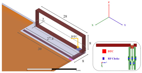
Figure 1.
Antenna geometry.
The equivalent circuit of the antenna is shown in Figure 2. The proposed antenna generally consists of three main parts: the matching circuit, the radiating element, and the DTC model. First, the matching circuit was designed as an open stub at the antenna input. Changing the length or width of this element allows for the antenna impedance to be matched for different values of the DTC capacitor. The open stub dimensions were chosen so that the antenna impedance was optimal at the intermediate values of the DTC, and less good for the higher and lower capacitance values. Due to this concept, antenna coverage could be ensured for all frequencies when the DTC was reconfigured. Second, the radiating element is described by a group of RLC components. These components’ values are characterized on the basis of the antenna shape and dimensions. Third, the DTC element was modeled as a capacitor in series with a parasitic resistor. Capacitance varied from 0.38 to 4.32 pF on the basis of the characteristics of the DTC component announced in the data sheet. According to the equivalent circuit structure, the resonance frequency of the antenna decreases if the capacitance value of DTC increases and vice versa.
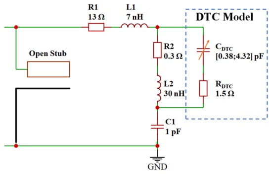
Figure 2.
Equivalent circuit of the antenna.
Two similar antennas were simulated using ANSYS EM high-frequency structure synthesizer software. The structure was designed on a 0.8 mm thick FR4 substrate with = 4.4, tan = 0.02, and a 35 m-copper thickness. Both antennas had the same dimensions, as shown in Figure 3. To obtain tuneability at the resonance frequency, a DTC was positioned at the top of the monopole.
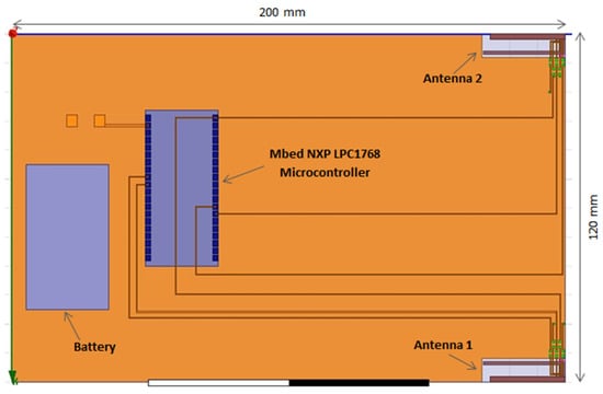
Figure 3.
Top view of the proposed antenna.
2.2. Digitally Tunable Capacitor
A digitally tuneable capacitor is an active component manufactured by the pSemi-Murata company (Figure 4). The item is compatible with the reconfigurable frequency antenna due to the RF power handling capability of up to 34 dBm while maintaining a low current consumption of 30 A. The DTC also offers the highest quality factor and a wide power supply range of 2.3–3.6 V.
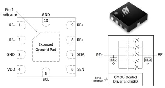
Figure 4.
DTC structure and its pinout.
Unlike a conventional varactor, DTC is quite simple to control thanks to the serial interface. Instead of regulating with the complex tuning voltage circuit, the DTC uses I2C signals to allow for the capacitance to be changed digitally among the 32 states. Depending on the configuration, the capacitance of the DTC varies from 0.38 to 4.32 pF for series connections, and from 0.9 to 4.6 pF for shunt connections. In this proposal, the configuration shunt was used with the radiating element that was connected to the DTC via RF + and RF−. By using the evaluation kit of DTC, the capacitance values were measured in the white-space frequency band in different states. The specifications provided by the manufacturer, and the measurement results are shown in the Table 1. In general, these values were quite similar.

Table 1.
Digitally tuneable capacitor values.
3. Simulation Results
To verify the reconfigurable scheme, the proposed antenna performance was analyzed and optimized using ANSYS EM software. The simulated antenna reflection coefficients are shown in Figure 5, with S11 lower than −6 dB in the white-space frequency band. According to the result, instead of using all the states of the DTC, only States 4 to 21 were applied.
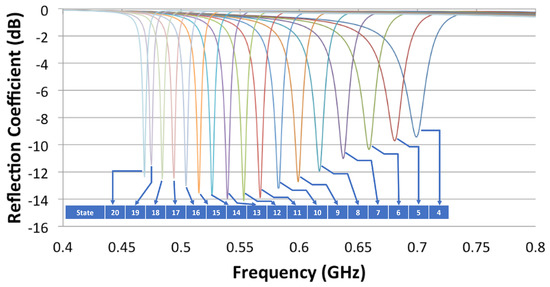
Figure 5.
Simulated antenna reflection coefficient.
To verify the performance of multiple resonances, these antennas were set to operate at different frequencies. In addition to checking the reflection coefficients, isolation between ports should be considered. Thus, three configurations were simulated with the specifications shown in Table 2.
Table 2.
Configuration of multiple resonances.
The simulated results of the S parameter are reported in Figure 6, Figure 7 and Figure 8 for Configurations 1–3, respectively. According to the figures, the antennas were matched with a reflection coefficient lower than −6 dB for all cases. In Configurations 1 and 2, the isolation values at 470 and 700 MHz were about −27 and −18.5 dB, respectively. These results confirm that the influence between antennas could be reduced. However, in Configuration 3, the isolation was −6.5 dB, which is an acceptable value while the distance between two antennas is relatively close (0.188 of wavelength at 470 MHz).
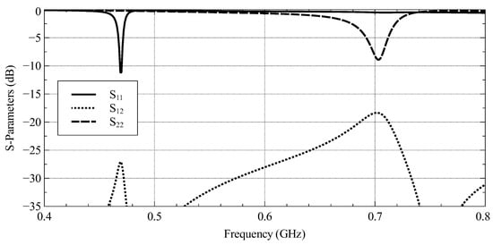
Figure 6.
Simulated S-parameters of antennas with Configuration 1.
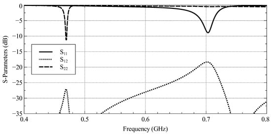
Figure 7.
Simulated S-Parameters of antennas with Configuration 2.
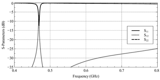
Figure 8.
Simulated S-Parameters of antennas with Configuration 3.
In terms of far-field radiation properties, the realized gain of the antennas is reported in Figure 9, Figure 10 and Figure 11 for Configurations 1–3, respectively. In general, the radiation patterns were omnidirectional, and the principal radiated planes were different. These depend on the radiated antenna and the resonant frequency. According to the results, the realized gains of the antennas were −2.2 dBi and 1.87 dBi at frequencies of 470 and 700 MHz, respectively.
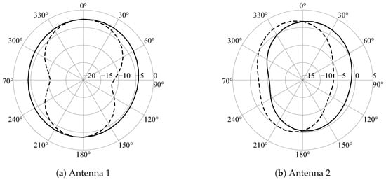
Figure 9.
Realized gain of the antennas with (solid line) and (dashed line) for Configuration 1.
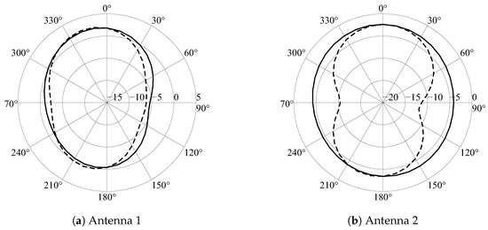
Figure 10.
Realized gain of the antennas with (solid line) and (dashed line) for Configuration 2.
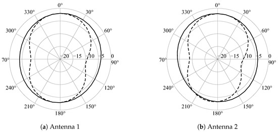
Figure 11.
Realized gain of the antennas with (solid line) and (dashed line) for Configuration 3.
According to the results shown in Figure 9, Figure 10 and Figure 11, the proposed antennas had a quasiomnidirectional pattern for the different configurations. Furthermore, despite the antenna operating at the same frequency, there were differences in the antenna radiation patterns, which shows the independence of the antenna performance, and contributed to reducing the ECC value. This can be explained by the effects of the ground plane on antennas when their positions were placed at the board corners.
4. Measurement Results
The antenna prototype was manufactured using the FR4 epoxy board shown in Figure 12. The antenna radiating elements were the bending metal plates soldered on the strip lines at the corners. The DTC components were also placed on these strip lines. Each DTC was connected to the control unit via five metal lines: VCC, GND for the power supply and SDA, SCL, ADDR for the serial interface. By adding RF choke inductors, the control signals could be isolated to the RF path. There was a large unused area in the prototype. In general, this place is reserved for the electronic circuit, battery, and display part of the real device. An Mbed NXP LPC1768 board was soldered onto this zone to program the DTC.
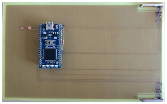
Figure 12.
Top view of the proposed antenna prototype.
By loading the embedded code, the capacitance value could be varied. Then, the antenna resonance was switched from 0.47 to 0.7 GHz to cover all white-space frequency bands. The prototype was measured using the N55227A PNA network analyzer and is reported in Figure 13. According to the results, the proposed structure needed only 19 states to cover all required bands with a reflection coefficient lower than −6 dB. Moreover, the continuity coverage scheme was obtained while using a discrete variable capacitor type thanks to the wide bandwidth at each DTC state.
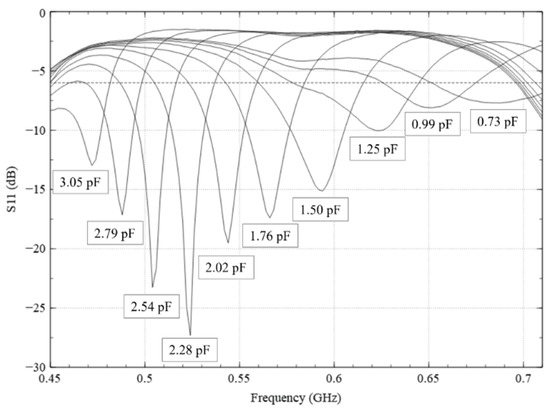
Figure 13.
Measured reflection coefficient of proposed antenna.
5. Antenna Diversity System
By applying antenna diversity techniques, the performance of mobile communication systems could be greatly enhanced. The envelope correlation coefficient (ECC) is the main parameter that characterizes the effect of correlation between two antennas. On the basis of [22], the ECC was determined using the far-field pattern data as shown in (1).
where and are the radiation patterns in the far field of Antennas 1 and 2 at different angles of and . This ECC value was calculated using the Scilab code, and the results are shown in Table 3. The value obtained at 700 MHz was relatively small, about 0.0481, while at 470 MHz, it was more significant, about 0.475. It can be explained by the fact that the wavelength at 470 MHz is longer than that of 700 MHz; therefore, the coupling between antennas at low frequencies is greater than that at high frequencies. Therefore, the mutual influence increases more. However, all of these values were less than 0.5; hence, a reduction in signal fading and a higher level of diversity gain could be achieved.
Table 3.
Envelope correlation coefficient.
6. Conclusions
This paper presented a reconfigurable antenna that operates at the white-space frequency band. By integrating the DTC components, the proposed structure could sweep the resonant frequency from 470 to 700 MHz. The S-parameter results show good agreement between the simulation and measurement. According to Table 4, the proposed structure has compact dimensions and is suitable for a portable device with a small clearance zone. With a high-loss, low-cost, and common material, this design is easy to use in real appliances. Furthermore, the relative bandwidth of 39.32% is comparable to that of related works. In addition, the antenna radiation properties were discussed with the realized gain of −2.2 dB at 470 MHz and 1.87 dB at 700 MHz. Due to its performance, the antenna could be a good candidate for a white-space application antenna.
Table 4.
Performance comparison with related works.
Author Contributions
Conceptualization, L.-H.T.; Data curation, L.-H.T.; Methodology, L.-H.T.; Software, L.-H.T. and F.F.; Supervision, F.F.; Validation, L.-H.T.; Writing—original draft, L.-H.T.; Writing—review & editing, L.-H.T. and F.F. All authors have read and agreed to the published version of the manuscript.
Funding
This research is funded by Vietnam National University HoChiMinh City (VNU-HCM) under grant number C2021-26-05.
Conflicts of Interest
The authors declare no conflict of interest.
References
- Zhou, H.; Zhang, N.; Bi, Y.; Yu, Q.; Shen, X.S.; Shan, D.; Bai, F. TV White Space Enabled Connected Vehicle Networks: Challenges and Solutions. IEEE Netw. 2017, 31, 6–13. [Google Scholar] [CrossRef]
- Song, M.; Zheng, M. Ecology-based coexistence scheme for heterogeneous cognitive radio networks over TV white space. IET Commun. 2018, 12, 620–626. [Google Scholar] [CrossRef]
- Zhang, W.; Yang, J.; Zhang, G.; Yang, L.; Kiat Yeo, C. TV white space and its applications in future wireless networks and communications: A survey. IET Commun. 2018, 12, 2521–2532. [Google Scholar] [CrossRef]
- Rahman, M.; Ismail, D.; Modekurthy, V.P.; Saifullah, A. LPWAN in the TV White Spaces: A Practical Implementation and Deployment Experiences. ACM Trans. Embed. Comput. Syst. 2021, 20, 1–26. [Google Scholar] [CrossRef]
- Petosa, A. An Overview of Tuning Techniques for Frequency-Agile Antennas. IEEE Antennas Propag. Mag. 2012, 54, 271–296. [Google Scholar] [CrossRef]
- Srivastava, S.; Singh, V.; Gupta, S.K. Reconfigurable Antenna for Cognitive Radio System. In Next-Generation Antennas, 1st ed.; Ranjan, P., Jhariya, D.K., Gupta, M., Kumar, K., Kumar, P., Eds.; Wiley: New York, NY, USA, 2021; pp. 143–154. [Google Scholar] [CrossRef]
- Kumar, S.; Rayavarapu, N. A unique frequency reconfigurable monopole antenna for TV white space applications. Frequenz 2022, 76, 361–366. [Google Scholar] [CrossRef]
- Bhole, S.; Rathod, A.; Doddipalli, S.; Kannaiyan, S.; Kothari, A. A Compact Planar Antenna with Meander lines for TV White Space Applications. In Proceedings of the 2018 IEEE International Students’ Conference on Electrical, Electronics and Computer Science (SCEECS), Bhopal, India, 24–25 February 2018; pp. 1–4. [Google Scholar] [CrossRef]
- Bouyedda, A.; Barelaud, B.; Gineste, L. Design and Realization of an UHF Frequency Reconfigurable Antenna for Hybrid Connectivity LPWAN and LEO Satellite Networks. Sensors 2021, 21, 5466. [Google Scholar] [CrossRef] [PubMed]
- Qin, P.Y.; Weily, A.R.; Guo, Y.J.; Bird, T.S.; Liang, C.H. Frequency Reconfigurable Quasi-Yagi Folded Dipole Antenna. IEEE Trans. Antennas Propag. 2010, 58, 2742–2747. [Google Scholar] [CrossRef]
- Liao, W.J.; Chou, S.H.; Chen, Y.A.; Lee, Y.; Ho, M.C.; Wu, P.Y. Frequency reconfigurable antenna for VHF/UHF digital TV reception on portable devices using switching matching networks. Microw. Opt. Technol. Lett. 2017, 59, 2800–2806. [Google Scholar] [CrossRef]
- Abou Shahine, M.Y.; Al-Husseini, M.; Nasser, Y.; Kabalan, K.Y.; El-Hajj, A. A reconfigurable miniaturized spiral monopole antenna for TV white spaces. In Proceedings of the Progress in Electromagnetic Research Symposium, Stockholm, Sweden, 12 August 2013. [Google Scholar]
- Patel, S.K.; Argyropoulos, C.; Kosta, Y.P. Pattern controlled and frequency tunable microstrip antenna loaded with multiple split ring resonators. IET Microw. Antennas Propag. 2018, 12, 390–394. [Google Scholar] [CrossRef]
- Anagnostou, D.E.; Chryssomallis, M.T.; Braaten, B.D.; Ebel, J.L.; Sepulveda, N. Reconfigurable UWB Antenna with RF-MEMS for On-Demand WLAN Rejection. IEEE Trans. Antennas Propag. 2014, 62, 602–608. [Google Scholar] [CrossRef]
- Huitema, L.; Reveyrand, T.; Mattei, J.L.; Arnaud, E.; Decroze, C.; Monediere, T. Frequency Tunable Antenna Using a Magneto-Dielectric Material for DVB-H Application. IEEE Trans. Antennas Propag. 2013, 61, 4456–4466. [Google Scholar] [CrossRef]
- Chiu, S.C.; Yang, L.Y.O.; Lai, C.P.; Chen, S.Y. Compact CRLH Asymmetric-CPS Resonant Antenna with Frequency Agility. IEEE Trans. Antennas Propag. 2014, 62, 527–534. [Google Scholar] [CrossRef]
- Liu, L.; Rigelsford, J.; Langley, R. Tunable Multiband Handset Antenna Operating at VHF and UHF Bands. IEEE Trans. Antennas Propag. 2013, 61, 3790–3796. [Google Scholar] [CrossRef]
- Hussain, R.; Alhuwaimel, S.I.; Algarni, A.M.; Aljaloud, K.; Hussain, N. A Compact Sub-GHz Wide Tunable Antenna Design for IoT Applications. Electronics 2022, 11, 1074. [Google Scholar] [CrossRef]
- Tang, S.C.; Wang, X.Y.; Zheng, S.Y.; Pan, Y.M.; Chen, J.X. Frequency-Reconfigurable Dielectric Patch Antenna with Bandwidth Enhancement. IEEE Trans. Antennas Propag. 2022, 70, 2510–2519. [Google Scholar] [CrossRef]
- Houret, T.; Lizzi, L.; Ferrero, F.; Danchesi, C.; Boudaud, S. DTC-Enabled Frequency-Tunable Inverted-F Antenna for IoT Applications. IEEE Antennas Wirel. Propag. Lett. 2020, 19, 307–311. [Google Scholar] [CrossRef]
- Asadallah, F.; Shehadeh, G.; Costantine, J.; Tawk, Y.; Eid, A.; Tentzeris, M.M. A Digitally Tuned Flexible Reconfigurable Antenna for IoT Devices. In Proceedings of the 2020 IEEE International Symposium on Antennas and Propagation and North American Radio Science Meeting, Montreal, QC, Canada, 5–10 July 2020; pp. 1803–1804. [Google Scholar] [CrossRef]
- Kildal, P.S. Foundations of Antenna Engineering: A Unified Approach for Line-of-Sight and Multipath; Artech House: Norwood, MA, USA, 2015. [Google Scholar]


Publisher’s Note: MDPI stays neutral with regard to jurisdictional claims in published maps and institutional affiliations. |
© 2022 by the authors. Licensee MDPI, Basel, Switzerland. This article is an open access article distributed under the terms and conditions of the Creative Commons Attribution (CC BY) license (https://creativecommons.org/licenses/by/4.0/).