Abstract
This paper proposes a robotic system that automatically identifies and removes spatters generated while removing the back-bead left after the electric resistance welding of the outer and inner surfaces during pipe production. Traditionally, to remove internal spatters on the front and rear of small pipes with diameters of 18–25 cm and lengths of up to 12 m, first, the spatter locations (direction and length) are determined using a camera that is inserted into the pipe, and then a manual grinder is introduced up to the point where spatters were detected. To optimize this process, the proposed robotic system automatically detects spatters by analyzing the images from a front camera and removes them, using a grinder module, based on the spatter location and the circumferential coordinates provided by the detection step. The proposed robot can save work time by reducing the required manual work from two points (the front and back of the pipe) to a single point. Image recognition enables the detection of spatters with sizes between 0.1 and 10 cm with 94% accuracy. The internal average roughness, Ra, of the pipe was confirmed to be 1 µm or less after the spatters were finally removed.
1. Introduction
Various automation and robotic systems have been implemented to improve the efficiency of pipe production. This study focuses on the manufacturing of small electric-resistance-welded (ERW) pipes with thicknesses of 10–20 mm and outer diameters of 10–60 cm. Owing to the nature of the process, spatters occur during ERW due to changes in the current and material composition. Thus, residual beads and weld seams generated by ERW exist inside pipes and must be removed by inserting a tool [1,2]. During the removal process, the roller of the tool presses the spatters against the inner surface of the pipe, causing them to adhere. After a subsequent tube expansion process, such as the one performed in a stretch-reducing mill, eye-shaped tears or eye-ball defects may occur.
Ge et al. [3] utilized a KUKA robot to perform weld seam tracking and polishing on the outside of pipes using a polishing machine and laser vision equipment. Pan-diyan et al. [4] performed grinding through a robotic abrasive belt to remove weld seams. These can remove weld seams on the outer surface of a pipe using a manipulator and have relatively no restriction on space. However, in the case of the insides of pipes, the space is narrow, and a small robot must be fused with its own driving force, grinding equipment, and vision systems. Zi-Li et al. [5] developed a wheel-drive-based polishing robot to polish weld beads inside medium-sized pipes (550–714 mm).
To remove spatters at the production site, workers attach a camera to a long rod and use it to inspect the inside of the pipe on a monitor. After visually checking the spatters and marking the corresponding distance on the rod, they move a manual grinder up to the marked distance and operate it to remove the spatters. Because the maximum length of the pipe is 12 m, the operator must inspect up to 6 m from either the front or rear ends before finishing production.
A method that is adaptable to multiple pipe diameters has been suggested for robotic systems that inspect and clean the insides of pipes [5,6,7,8], especially in the case of actual industrial sites, where various obstacles, such as horizontal, vertical, and branching obstacles, appear in the piping configuration, urging a solution to interconnect multiple modules and overcome the obstacles [9].
In this paper, a spiral mechanism for the configuration of the driving wheel and a slider crank with a spring link that can adjust to the internal diameters of small pipes with diameters of 18–25 cm were proposed. The mechanisms were designed as part of a structure that can control speed and torque. Image recognition technology was applied to detect spatters inside a pipe. The proposed robot automatically grinds spatters after checking their distance and circumferential position inside the pipe.
Spatters are granules are generated when the combination of current and voltage is not appropriate during welding or when the molten metal in the welding rod or wire is not fused to the base material of the welding part. This is typically due to poor contact with the earth or to the melting and adherence of the granules around the weld. Spatters must be removed because they can cause defects.
This study presents a spatter-grinding robot (SGR) that automatically detects spatters in a small pipe while moving inside it, records the detected position in a database, moves to the end of the pipe, and then moves back to automatically grind the detected spatters.
2. SGR Design
The design elements, hardware configuration, and control systems required for the SGR design must be accurately analyzed. The main requirements for the SGR are as follows [10,11]:
- It should be able to operate within small pipes with diameters of 15–25 cm;
- It should have the ability to drive, detect spatters, and grind them in a narrow space;
- Driving errors should be minimized when slip occurs inside a steel pipe;
- The spatter position should be accurately recorded to prevent damage to the base material during grinding.
The design of the pipe robot for driving, inspection, and grinding work inside the pipe comprises a link structure that can maintain the center of the robot in the center of the pipe according to the required diameter via a driving wheel. In the case of a pipe robot with a large diameter, a system that transmits traction force directly by configuring a motor and a reducer on the driving wheel unit can be configured, but a pipe robot with a small diameter causes a space problem in the design of the driving wheel. Therefore, in the concept design of the pipe robot, the work head was configured on the front side and fixed, and a link was applied to the main driving module. A system is proposed that can control the driving speed by configuring a passive wheel on a spring-loaded rod in close contact with the pole and varying the pitch and rotational speed according to the spiral angle through the spiral rotation and steering of the passive wheel.
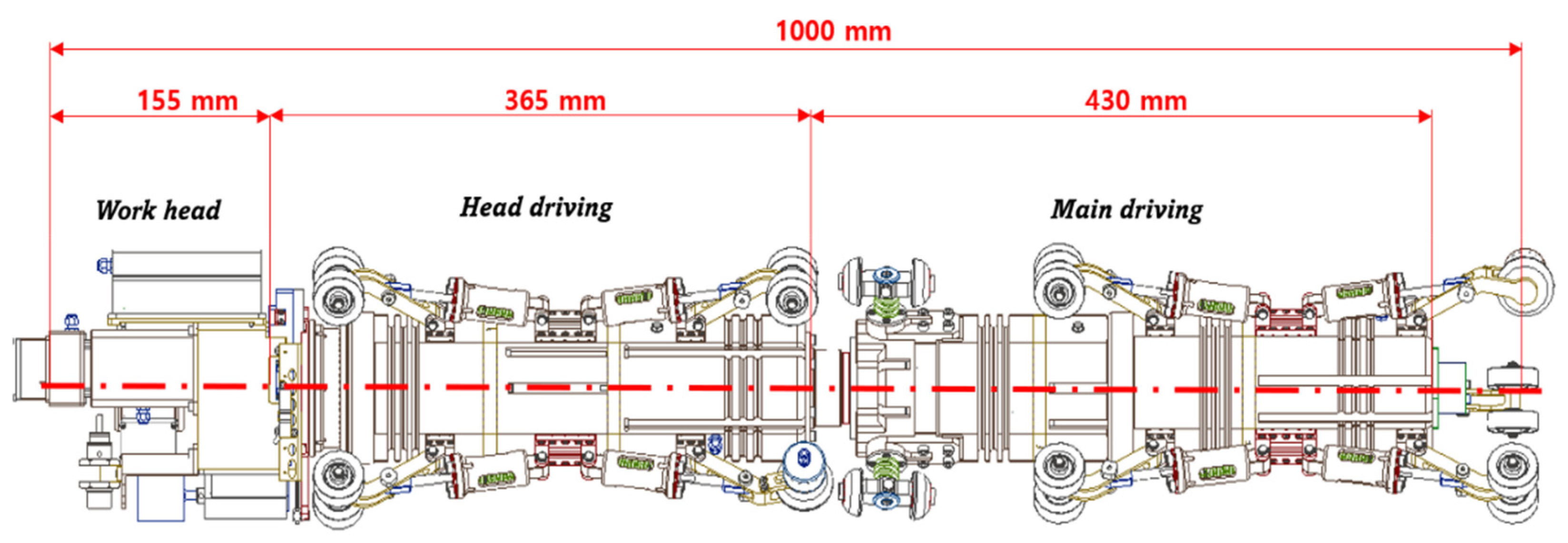
As shown in Figure 1, the proposed robot, which satisfies these conditions, comprises a work-head module with roll motion support for spatter detection and grinding, a head-driving module responsible for controlling the elevation drive, and a main driving module for spiral driving in the pipe.
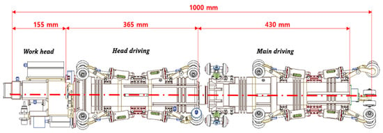
Figure 1.
Pipe spatter detection and grinding robot.
Because the robot must perform spatter detection, grinding, and driving inside pipes with diameters as low as 18 cm, if the diameter of the robot exceeds 4 in, it would be difficult to secure enough space to work and move inside the pipe. This results in a minimum design requirement that the various components, such as the motor, reducer, controller, sensor, and camera, must be able to be installed inside an SGR with a maximum size of 4 in. Furthermore, it is important to design an optimal expansion link, motor, and reducer for horizontal and vertical driving within a pipe.
Driving inside a pipe can be largely divided into two types, wheel or caterpillar, depending, respectively, on whether a motor and reducer are applied directly to the driving wheels or the power is transmitted through a belt structure. There are limits to the overall mechanical size of the structure that constrain the design of many mechanical elements, motors, and reducers to transmit power as well as design limits for the optimization of the driving mechanism suitable for small pipes. Therefore, in this paper, a spiral-type driving mechanism was proposed and designed, and a passive-type link structure was selected to enable adjustment to different pipe diameters [12,13,14,15,16].
Figure 1 shows the proposed robot platform, which can detect and grind spatters inside pipes. It was designed to run horizontally and vertically inside a pipe. Detailed specifications are listed in Table 1.

Table 1.
Robot specifications.
2.1. Work-Head Module
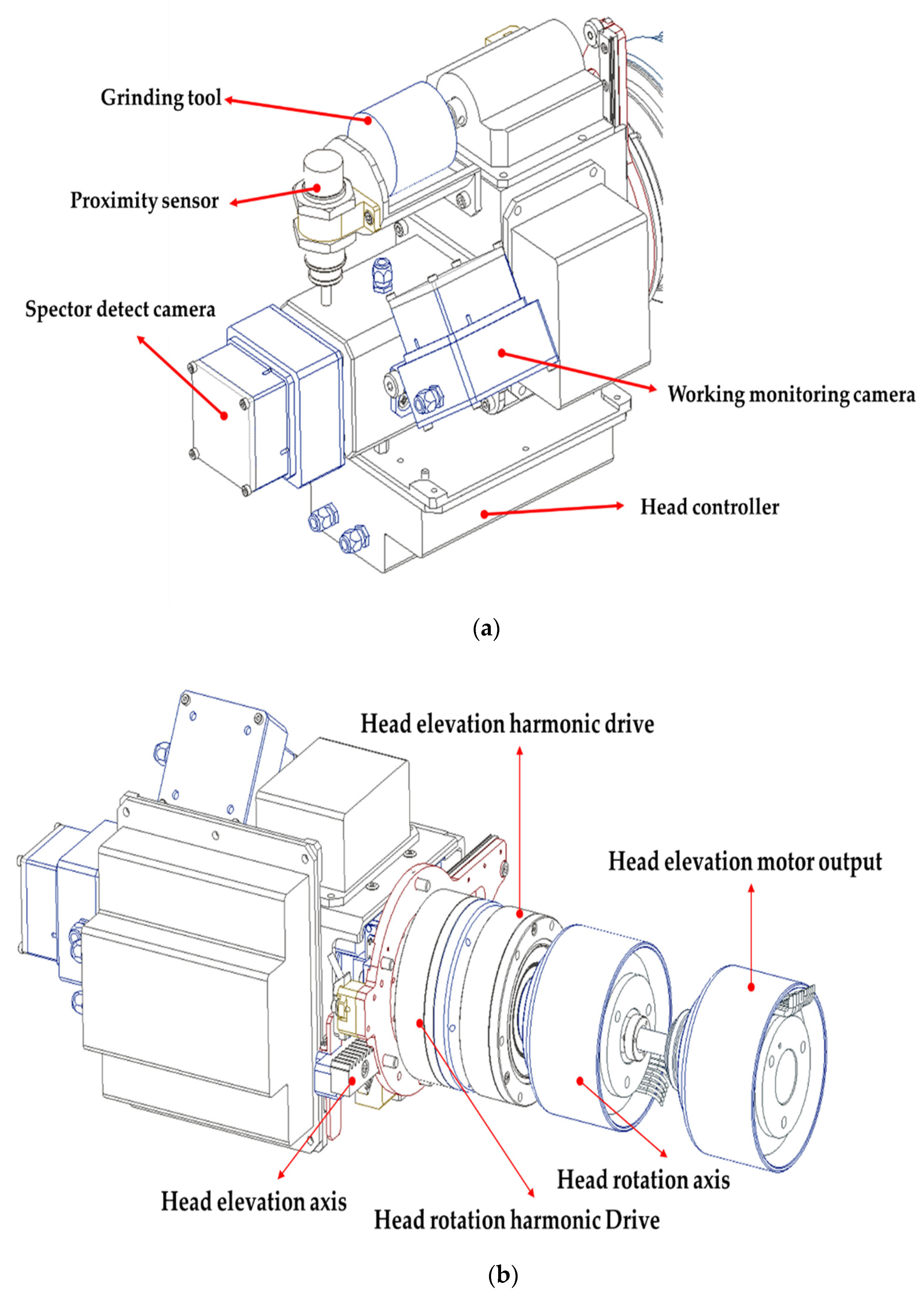
Figure 2a shows the configuration of the work-head module, which contains a vision camera for spatter detection through image recognition, a grinding tool for spatter removal, a proximity sensor for accurate absolute positioning of the spatters, a controller in charge of the grinding tool’s rpm and head-elevation control, and a monitoring camera for estimating the final quality after grinding.
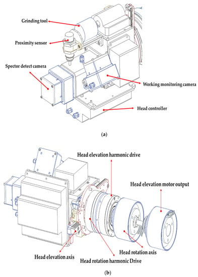
Figure 2.
Components and structure of the work-head module mechanism. (a) Work-head module components, (b) Grinding tool driving mechanism.
Because spatter detection through image recognition operates in dark conditions inside a small pipe, a high-resolution five-megapixel camera with a screen resolution of 2592 × 1944@15 fps was used. The captured images were processed by an image recognition algorithm, and spatter recognition and positioning were performed. The results of the image recognition include information on the direction and location of the spatters in terms of circumferential coordinates. The head is rotated to the corresponding coordinates to check the accuracy of the height information transmitted to the spatter-grinding tool. The correct height can be confirmed if the head elevation is lowered until the detection is completed by the proximity sensor. This removes spatters only during the grinding process and helps protect the base material on the pipe surface.
The components of the working head-driving mechanism are shown in Figure 2b. The working tool was designed to rotate because spatters may be attached to the inner surface of the pipe in the circumferential direction. The work-head module rotation axis serves to rotate the grinding tool based on the detected position and direction of the spatters. Moreover, the head-elevation axis was designed with a rack and pinion structure to move the grinding tool to the detected spatter position. Because rotation and elevation must be simultaneously performed during grinding, the head-elevation motor output and head-rotation axis were designed as an integrated structure using bearings on the same axis.
2.2. Head-Driving Module
The driving module comprises the head-driving and main driving modules, as shown in Figure 1. The head-driving module consists of a passive mechanism provided with passive wheels, links, and springs appropriate for small pipe diameters. The links for supporting the center of the robot inside the pipe were placed at intervals of 120°. When the link is pressed by the pipe, the spring rod inside the suspension is pulled, and the spring between the spring rod and stopper is compressed. Furthermore, the module was manufactured in a structure that fits within the diameter of the pipe, thanks to the force that the link exerts in trying to expand in the radial direction.
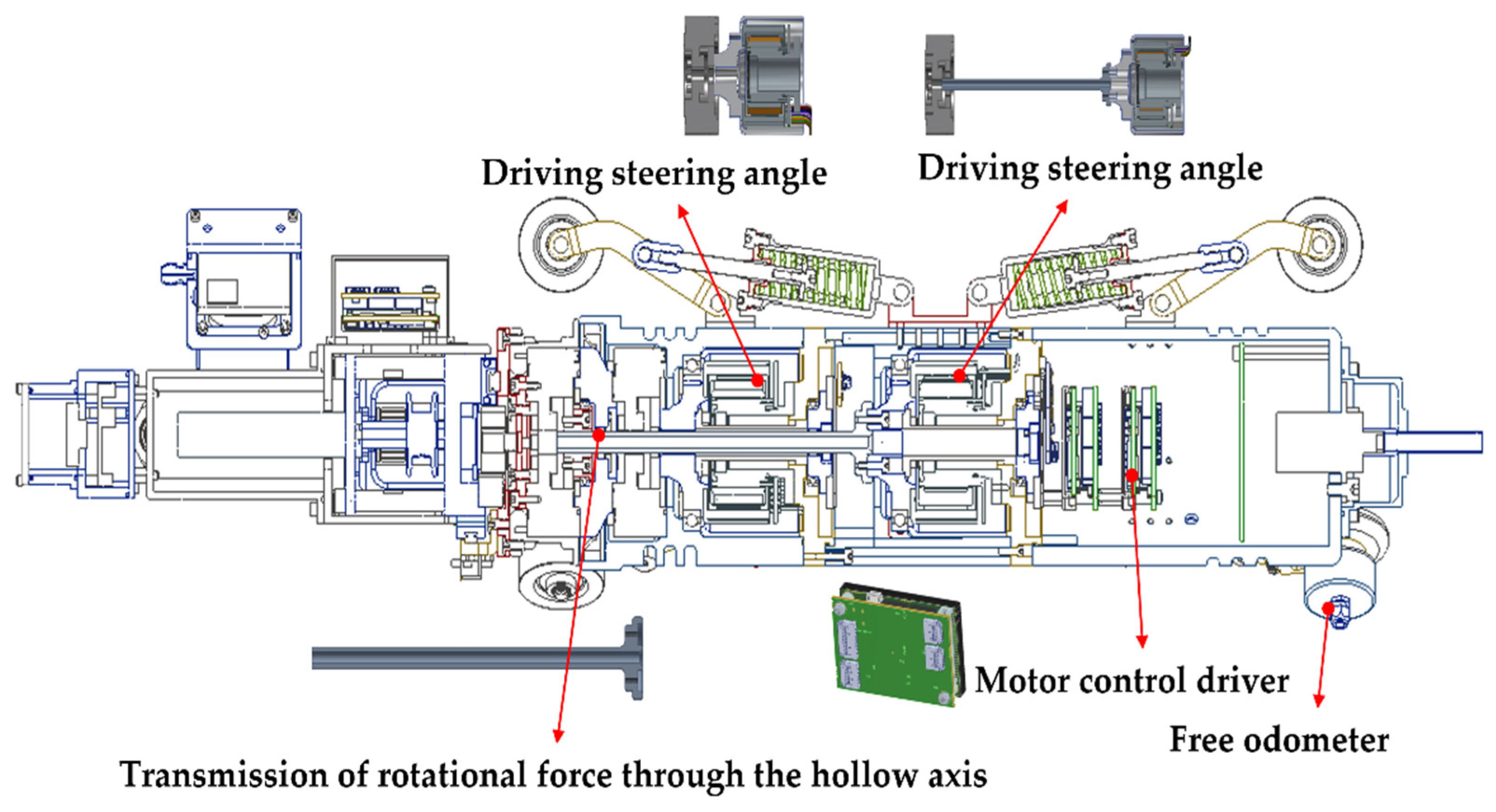
The mechanical configuration required for the head-driving module to support the operation of the work-head module is shown in Figure 3. It includes a motor, a reducer, and a controller for the rotation and elevation of the work head. The motor output torque is transmitted to the elevation shaft using a hollow shaft, and a free odometer was installed to monitor the exact robot position. Because there may be errors in the position of the robot due to slipping of the driving wheels in the pipe or other reasons, the design includes the capability to check the current position of the robot and the exact position of the spatter using a free odometer.
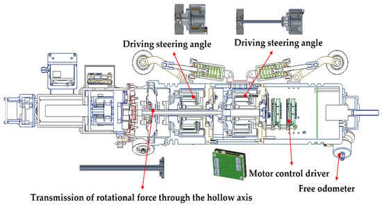
Figure 3.
Head-driving module design.
2.3. Main Driving Module
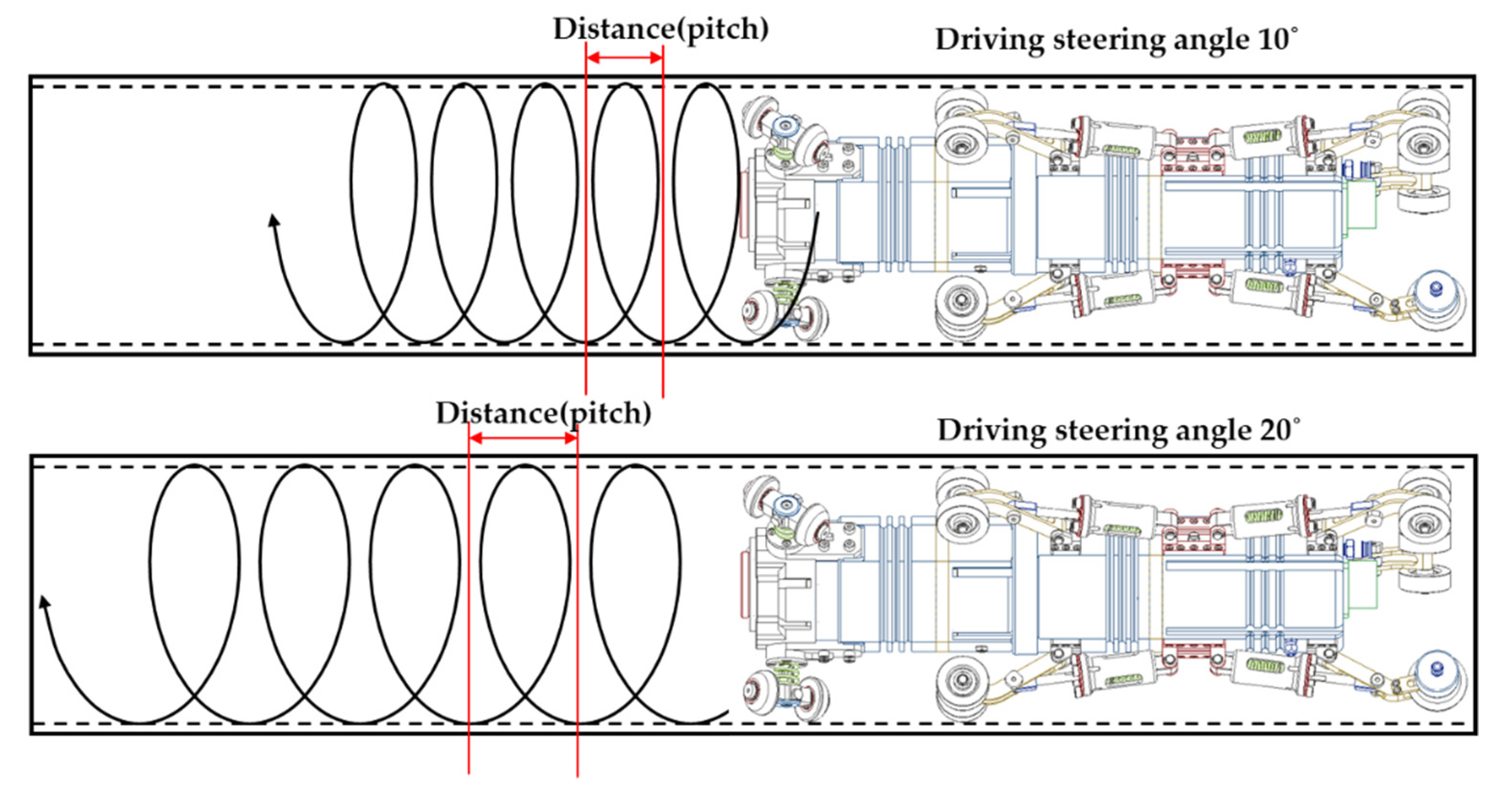
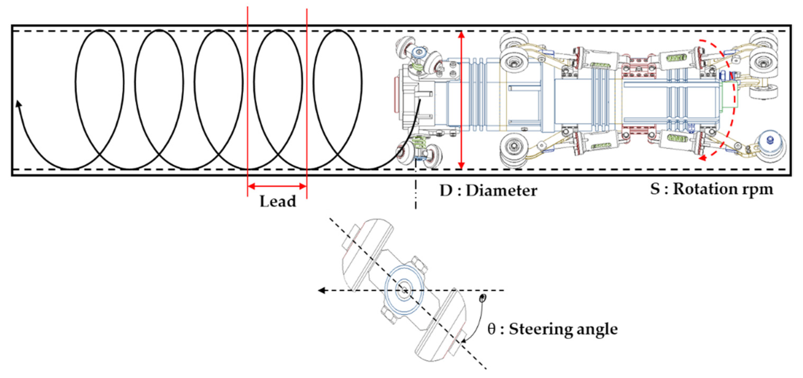
The main driving module is responsible for driving the robot. In this study, a method was devised to drive the robot in a spiral fashion inside the target pipes. The driving distance (pitch) and speed increase or decrease according to the inclination of the driving wheel, as shown in Figure 4.
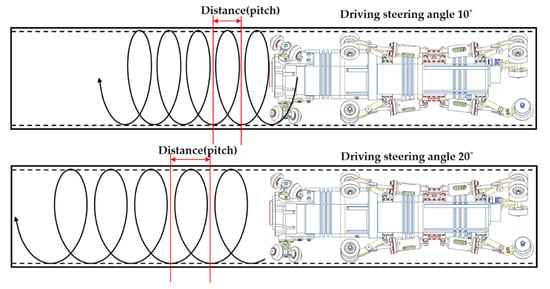
Figure 4.
Driving-distance control based on wheel inclination.
Since the driving distance changes according to the steering angle of the driving wheel, the driving distance can be confirmed by determining the driving steering angle, as shown in Figure 4. Furthermore, since the speed of the robot is proportional to the distance, the driving steering angle affects the speed of the robot as well. If the driving-rotation speed is adjusted according to the change in the driving distance, the robot’s driving speed can be controlled, allowing for effective driving in a small pipe. However, compared to the conventional method, with the proposed design, torque can be distributed equally to all wheels grounded inside the pipe because rotation is generated and driven inside the module.
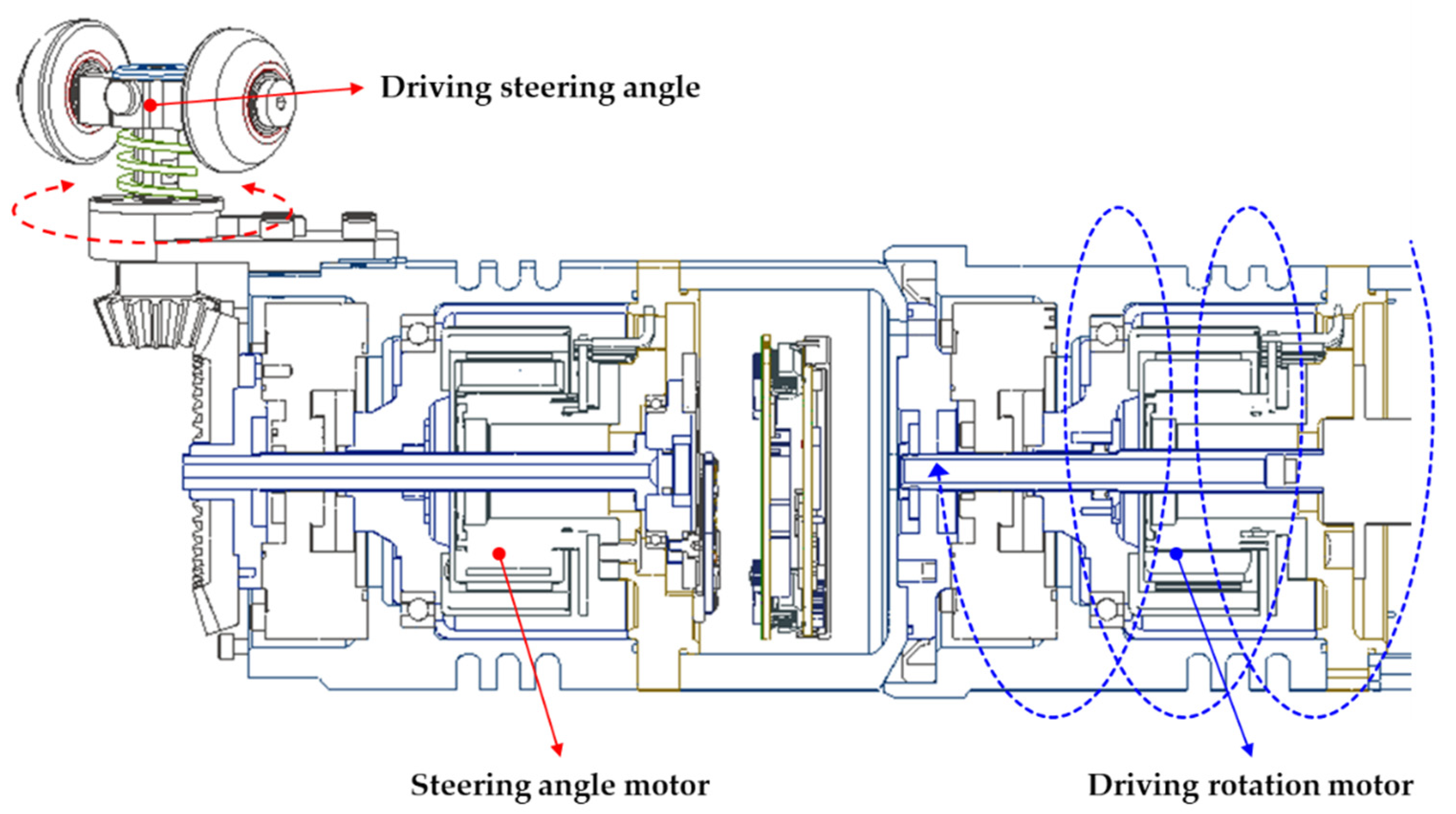
Figure 5 shows the steering-angle and driving-rotation motors in the main driving module. The power and speed when moving forward and backward inside the pipe can be controlled using the steering angle and driving rotation.
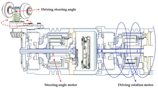
Figure 5.
Driving rotation and steering design.
3. Spatter Image Recognition
The spatters generated by welding are shaped like droplets and are also known in the field as eye balls because they exhibit the shape of a human eye. An image recognition method based on the consideration of this geometry was applied.
The image processing captures real-time stream image input with the IP camera through ethernet cables connected to the robot and integrates with user programs via the user task teaching pendant to a C#-based algorithm to store coordinate values through image processing in DB.
As shown in Figure 6, the images captured by the robot’s front camera undergo various steps: image acquisition, preprocessing, region-of-interest (ROI) setting, and spatter detection. The input is quantized by the image sensor and transformed into a two-dimensional pixel array and a three-channel RGB additive mixture. Color-based algorithms cannot be used because the colors inside the pipes vary depending on the pipe material. Therefore, a one-channel gray conversion is performed on the input image to improve efficiency and processing speed [16,17,18]. Various gray-conversion algorithms are used for this purpose. However, because the inside of the pipe is dark, when the robot approaches the pipe outlet, light-altered pixels appear in the input image in the areas corresponding to the pipe opening and the edges of the picture. Therefore, in the gray-conversion process, the following gray-level transformation function was applied to improve spatter detection and convert the image into a one-channel gray image:
where M and H are the gray levels before and after conversion, respectively; represent the start and end points of each conversion section, respectively; is the conversion constant; R and C are the sizes of the input image; and and are the pixel indices.

Figure 6.
Flowchart of the spatter detection algorithm.
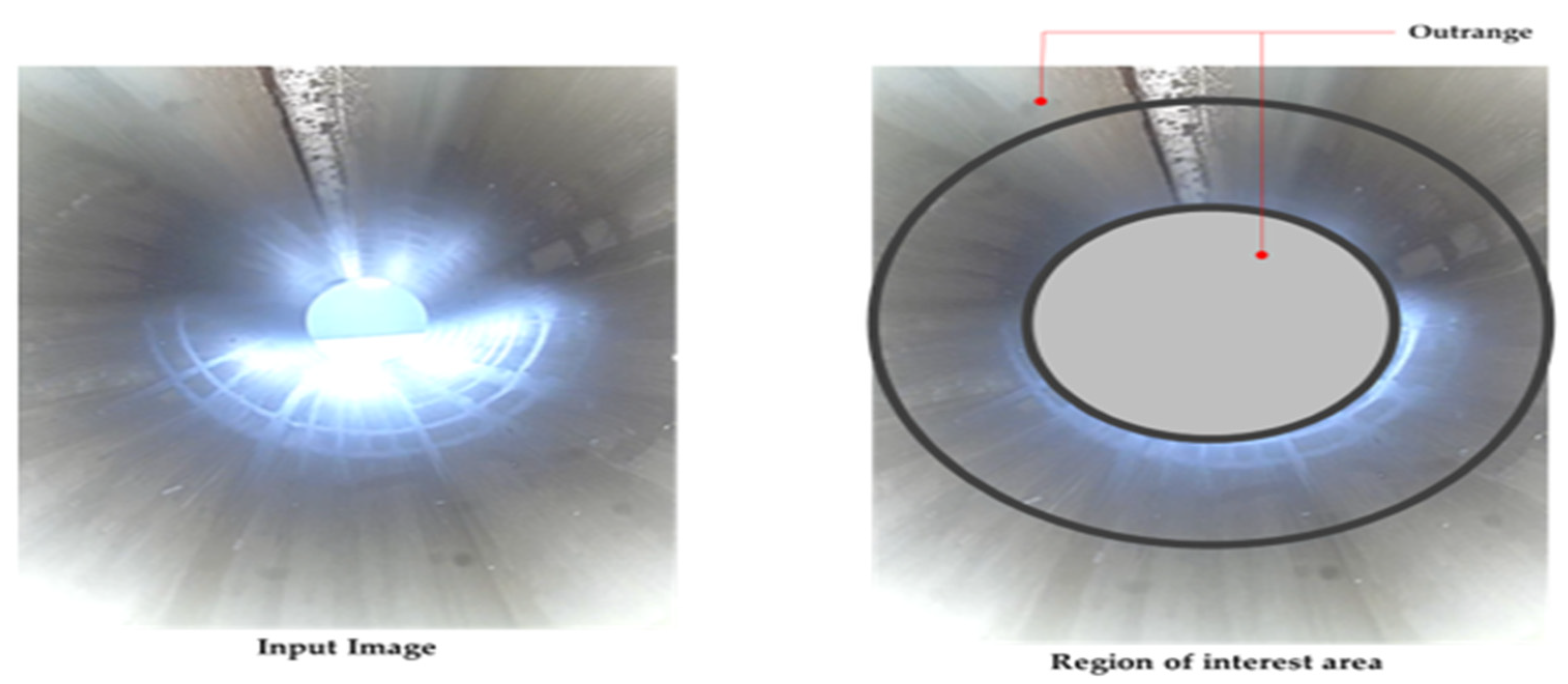
Inside the pipe, pixels that are affected by robot lighting and changes in illuminance that occur near the pipe exit appear in the input images, as shown in Figure 7. To mitigate this problem, the central part of the input image corresponding to the pipe outlet and the surrounding edges, which are affected by the lighting problem, are masked. Then, the remaining region is designated as the ROI. This method is advantageous in designating the ROI because the inner diameter of the pipe is known in advance, so the detection algorithm can be performed only on the designated area. In addition, because not all the pixels are processed using this ROI-limiting technique, the processing speed is improved by at least 20%.
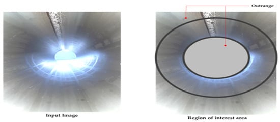
Figure 7.
Masked image with ROI.
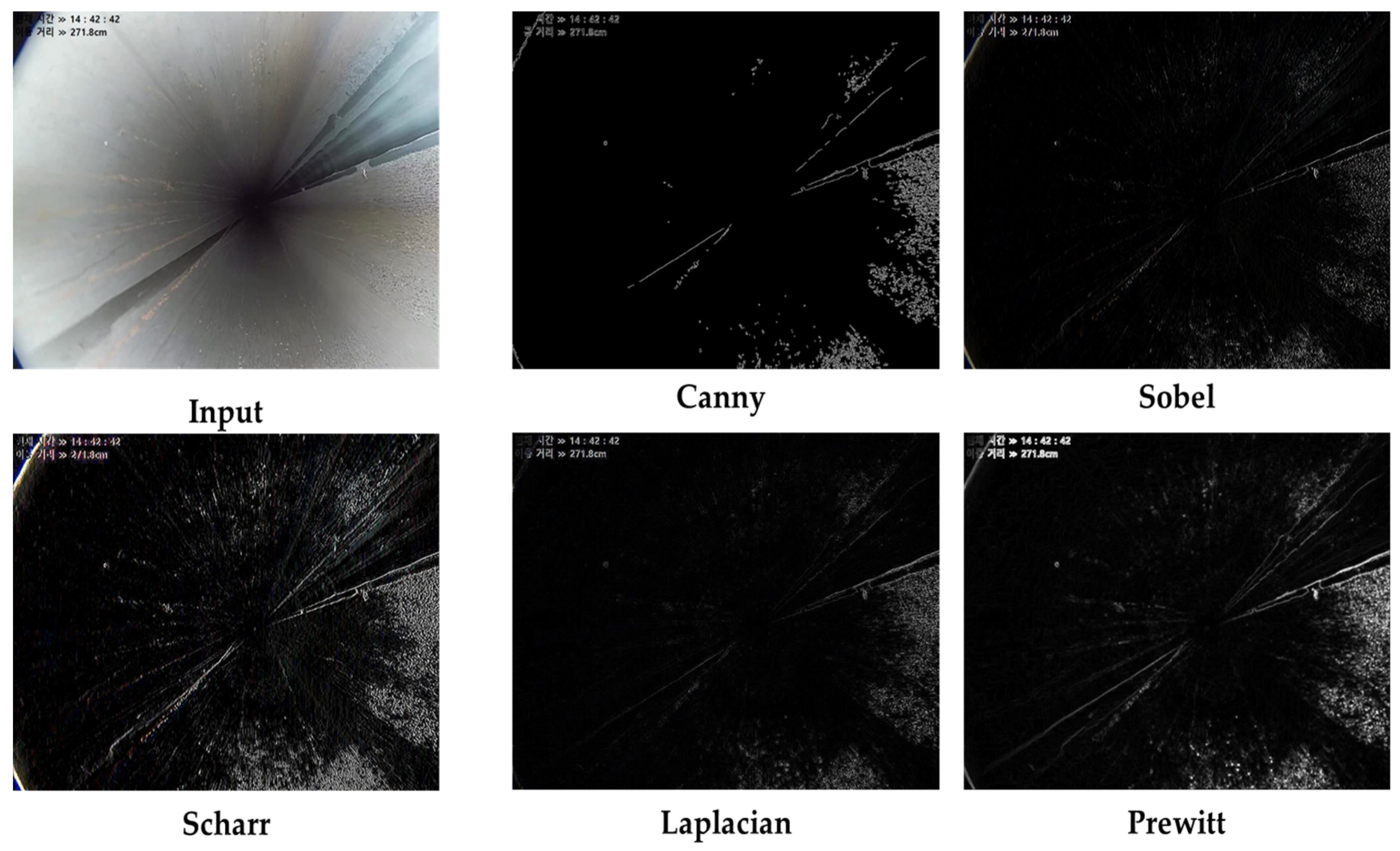
Finally, an algorithm is utilized to detect spatters via edge detection on the binarized image [19]. Various algorithms have been used for edge detection; in this study, the Canny [20], Sobel [21], Scharr [22], Laplacian [23], and Prewitt [24] models were analyzed and compared, as shown in Figure 8 and Table 2. The image quality of the results was evaluated based on the mean squared error (MSE) to select one of the compared models.
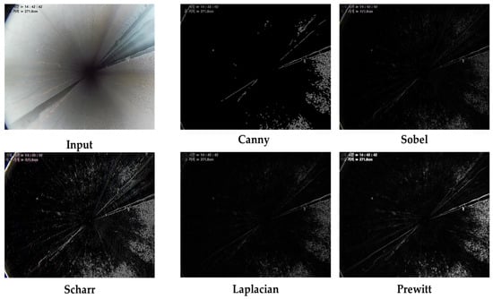
Figure 8.
Comparison of edge-detection models.

Table 2.
Comparison of models based on MSE.
Various edge-detection models were tested to determine which of them provides the fastest arithmetic processing for removing noise from the input image and minimizing the candidate group to be analyzed because it is necessary to rapidly detect spatters while moving through the pipe.
In the final preprocessed image, spatter detection is confirmed using the spatter-model-based image algorithm. Then, the position and circumferential angle for the spatters are calculated and returned to the robot database. These images are saved as a file only for future result confirmation and user convenience because the actual robot only converts and utilizes information, such as the current position, through the free odometer, and the angle in the circumferential direction at the spatter position, into the form of a structure.
4. Velocity Control
4.1. Velocity Control Method
Transmitting the rotational force of the motor directly and indirectly to the driving wheels to configure the SGR driving mechanism is limited. Instead, a spiral driving method is proposed in this study. As explained in Section 2, the robot’s acceleration/deceleration and driving speed can be controlled by adjusting the steering angle and driving-rotation motor. The motor specifications used in this study are summarized in Table 3.

Table 3.
Motor parameters (steering and driving).
To calculate the driving speed of the SGR, it is necessary to understand spiral driving. As shown in Figure 9, the driving speed is based on the steering angle and changes according to the lead.
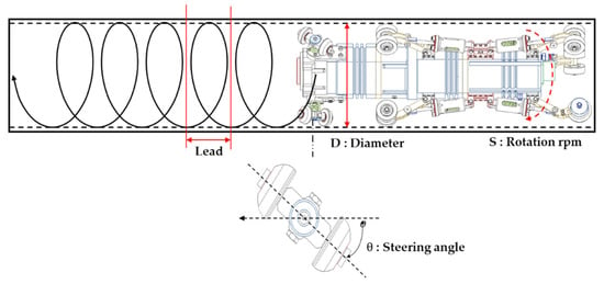
Figure 9.
Relationship between steering angle and rotation speed (rpm).
Thus, the robot’s driving velocity, according to the steering angle and rotation speed of the target pipe, can be expressed as follows:
where θ is the steering angle of the driving wheel, the lead is the spiral travel interval according to θ, D is the inner diameter of the pipe, and S is the rotation speed.
Table 4 exemplifies the spiral driving control method. For large pipe diameters, a high driving speed is possible with a small steering rotation. The torque of the steering-angle rotation motor has a proportional relationship with the pipe diameter; therefore, it is necessary to select a motor considering the required torque according to the pipe diameter.

Table 4.
Relation between driving angle and speed for different pipe diameters.
4.2. Dimensionless PID Control
When controlling the speed inside the pipe, there is a difference between the speed expected from the control input and the one that is actually achieved by the robot. This occurs because the link used to run the robot inside the pipe is grounded to the pipe surface by means of a strong force, which significantly affects the driving torque, thereby causing the mentioned difference between the input and actual speeds. Considering this, a closed-loop control algorithm is used to control the error by feeding back the current speed in real time [25,26].
However, there are other disturbances that may impact speed, such as mechanical errors and environmental factors inside the pipe. When such disturbances exist, controller design becomes difficult, and the design must consider various environments. Moreover, it is necessary to set the optimal gain through extensive time and experimentation. The driving characteristics of the proposed SGR require speed control based on a large external force and torque during spiral driving. Consequently, we adopted a standard proportional–integral–differential (PID) controller, assuming a primary time-delay system control target, as follows:
where is the normal gain, is the time constant, and is the time delay.
The performance of Equation (4) can improve if a higher-order model is used, which is currently a widely used option in industrial sites, and it can be approximated to a higher-order processor by appropriately adjusting its three parameters ().
For ease of analysis, the time delay can be defined as a dimensionless parameter ( by dividing the time, T, by the time constant, . When this parameter is replaced by the Laplace transformation , the relationship holds in the frequency domain. Hence, by setting , the dimensionless transfer function of the PID controller and the control object can be defined as follows:
Equation (5) represents the PID controller, and Equation (6) can be expressed in the time domain by the inverse Laplace transform on the control target as follows:
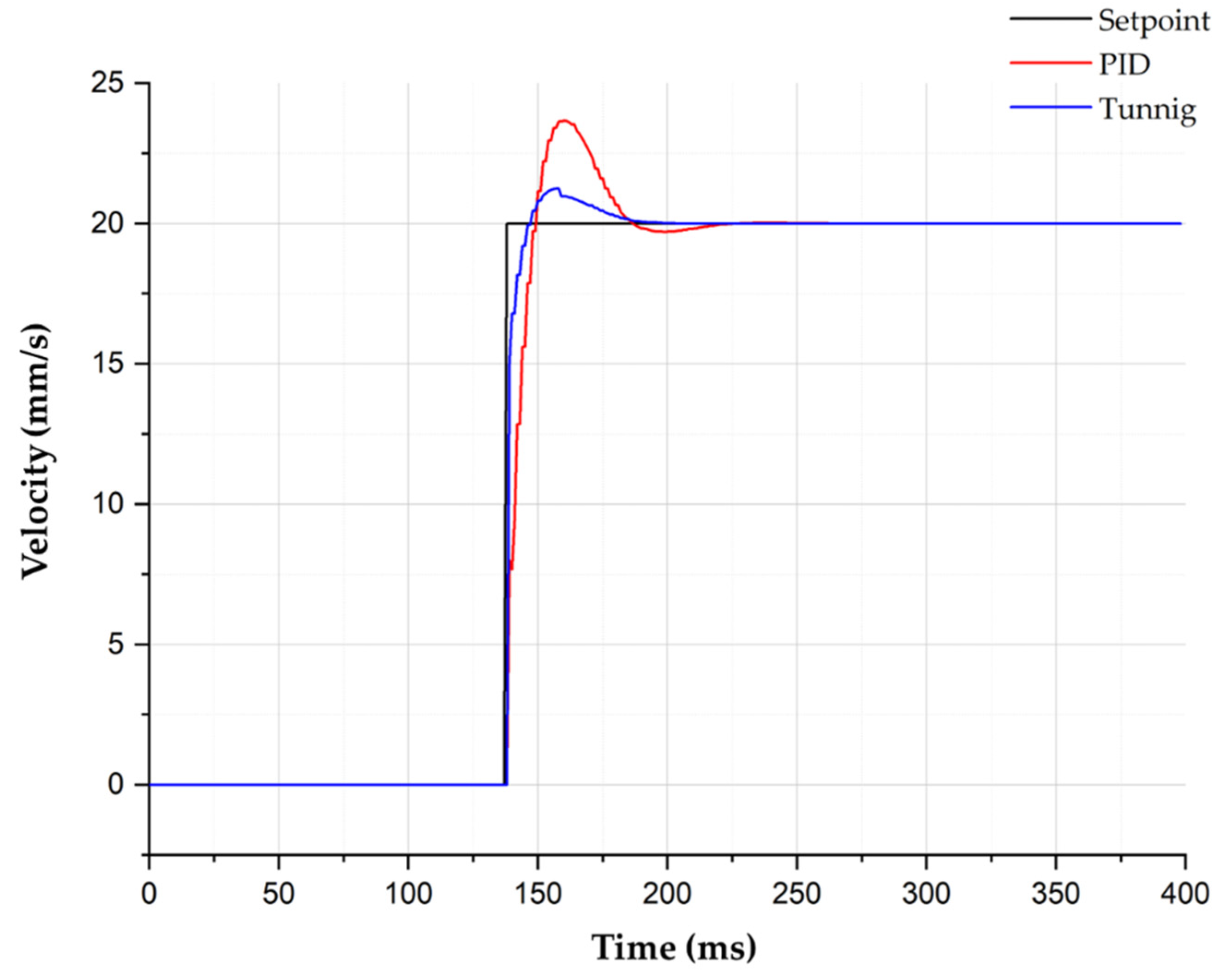
The block diagram of the final PID design is shown in Figure 10, where the transfer function is given by Equation (9). The Ziegler–Nichols method was applied to the selected model to set the current PID gain and optimal gain values of the robot controller. After setting the initial values of I and D while increasing the P gain, an appropriate gain value was derived using a table based on the frequency response through the critical gain in the critical state and the critical period. As shown in Figure 11, compared to the case before applying the optimal gain, the result quickly and stably follows the target value [10].

Figure 10.
Block diagram of the PID control system.
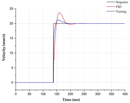
Figure 11.
Tuning of the speed control PID gain.
5. Robotic System Verification
Pipes, each with a diameter of 15 cm and a length of 8 m, which are typically used for industrial applications, were selected to verify the capacity of the proposed robot to drive inside pipes. Additionally, transparent acrylic pipes with diameters and lengths of 15 cm in and 2 m, respectively, were used to monitor the robot driving status and work-head control. Furthermore, the actual detection of spatters inside a steel pipe was verified in real time. In the acrylic pipe, the driving velocity was varied by adjusting the steering angle to evaluate the spiral driving feature. To verify the grinding performance, the robot was inserted into the acrylic pipe, a spatter on a flat plate at the end of the pipe was polished, and the surface roughness was measured after grinding.
5.1. Verification of Spatter Detection in Real Pipes
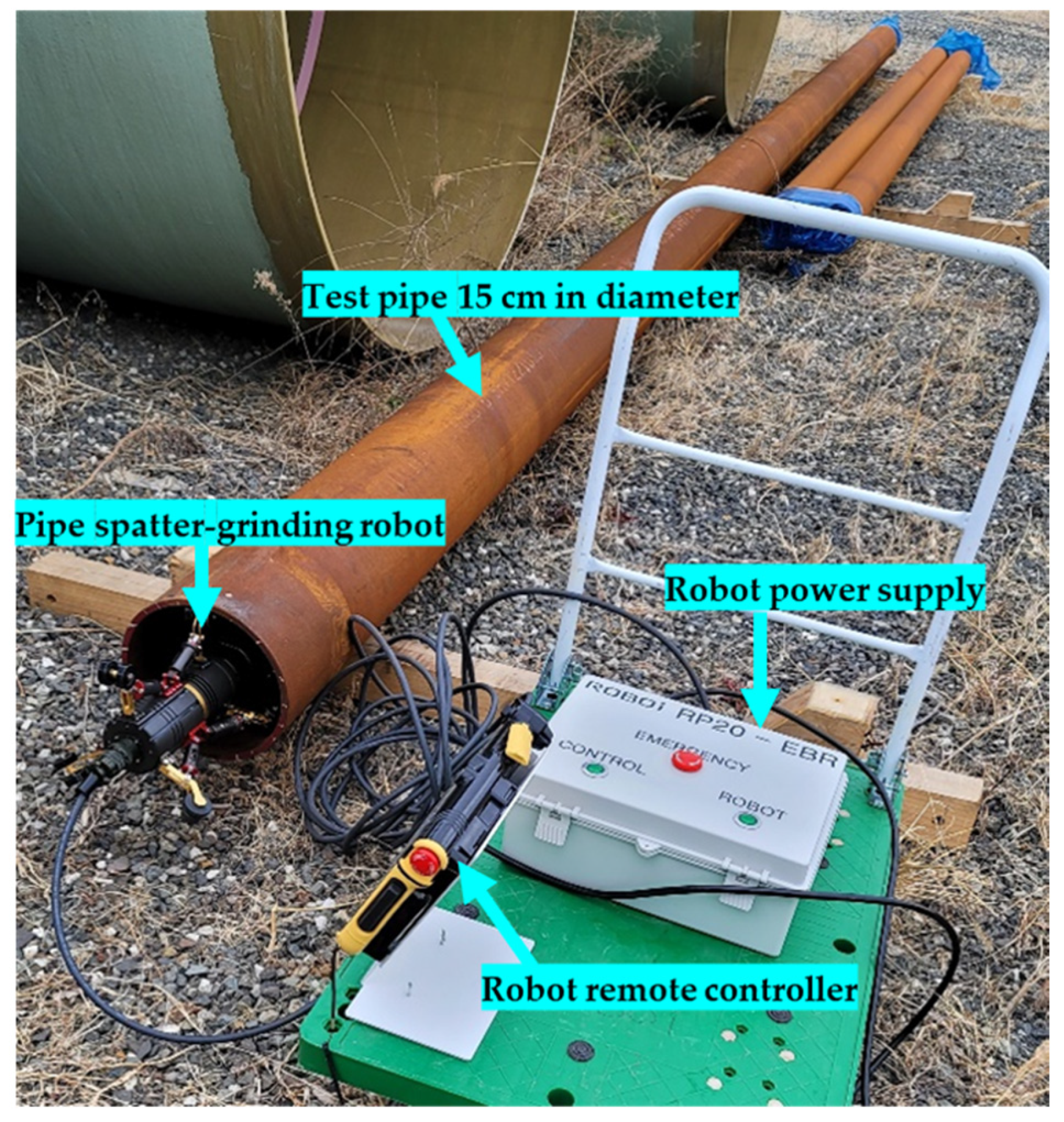
Pipes produced at the actual production site were supplied and tested. Figure 12 shows the manufactured SGR prototype, where for user workability the status of the front and grinding operations mounted on the robot could be checked through the teaching pendant. The operator did not manually remove spatters from the pipe, and the test was conducted on a pipe with a lot of spatters inside it. Figure 13 shows one of the provided pipes with a 15 cm diameter. The following equipment was used in the test: a power supply for the robot and for general work, a manipulator that could remotely control and monitor the robot, and a prototype of the proposed spatter detection and grinding robot that was designed and manufactured.

Figure 12.
SGR prototype.
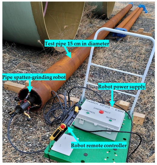
Figure 13.
Pipe spatter detection test.
As shown in Figure 14, the robot was inserted into the actual pipe, driving at a speed of 0.3 m/min, and the input image was analyzed in real time. A graphical user interface was designed so that the operator could intuitively check the location and information of the spatters identified using the proposed detection algorithm.

Figure 14.
Real-time spatter detection inside a test pipe.
Table 5 summarizes the image processing test results obtained for four pipes with 15 cm diameters with spatters, including the locations of the spatters in the pipe. The recalls and errors were computed based on the actual distance output, according to the actual image processing result. The total recall was 87.5%, and the error ranged from 0.1 to 10 cm. The main sources of error were confirmed to be mathematical rounding and the conversion from pixels to actual distance.

Table 5.
Image processing test results.
5.2. Verification of PID Gain Tuning
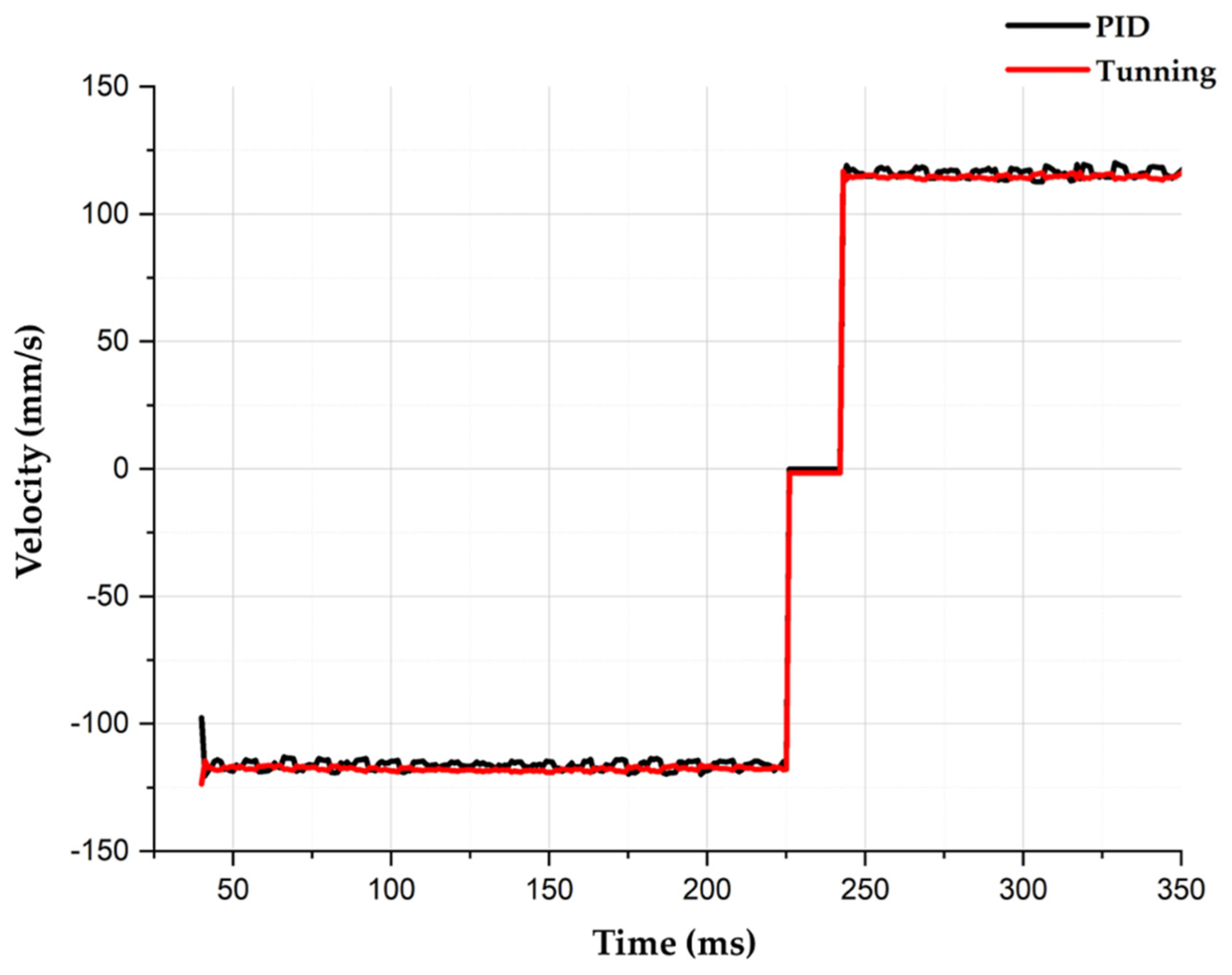
Because it is difficult to observe the robot’s driving pattern inside one of the produced steel pipes, the steering-angle change in the spiral driving wheel as well as the spiral driving method and speed were tested using acrylic pipes. The change in the angle of the spiral driving wheel was confirmed based on the driving speed inside the pipe. An experiment was conducted in the acrylic pipe to investigate the change in speed according to the previously applied gain and the optimal gain using the Ziegler–Nichols method while varying the driving speed from 280 to 1200 mm/sec. Considering the change in velocity, it was confirmed that the optimized gain enabled approximately twice the precision in velocity control compared to the existing PID gain. Table 6 shows the RMS of the feedback for each speed value in a pipe with a diameter of 20 cm.

Table 6.
RMS comparison between original and tuned PID.
Figure 15 shows the velocity profiles for the forward and reverse directions based on the original and optimized gains during spiral driving with a 20° steering angle in an acrylic pipe with a diameter of 20 cm. The optimized gain exhibited a control speed that was most similar to the target speed.
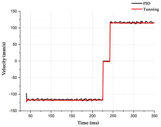
Figure 15.
Velocity profile based on gain.
5.3. Verification of Spatter Removal
It was not possible to confirm the grinding work inside the steel pipes with spatters used in the tests. Thus, an acrylic specimen of the same type was prepared to test the removal of a spatter at the entrance of the pipe.
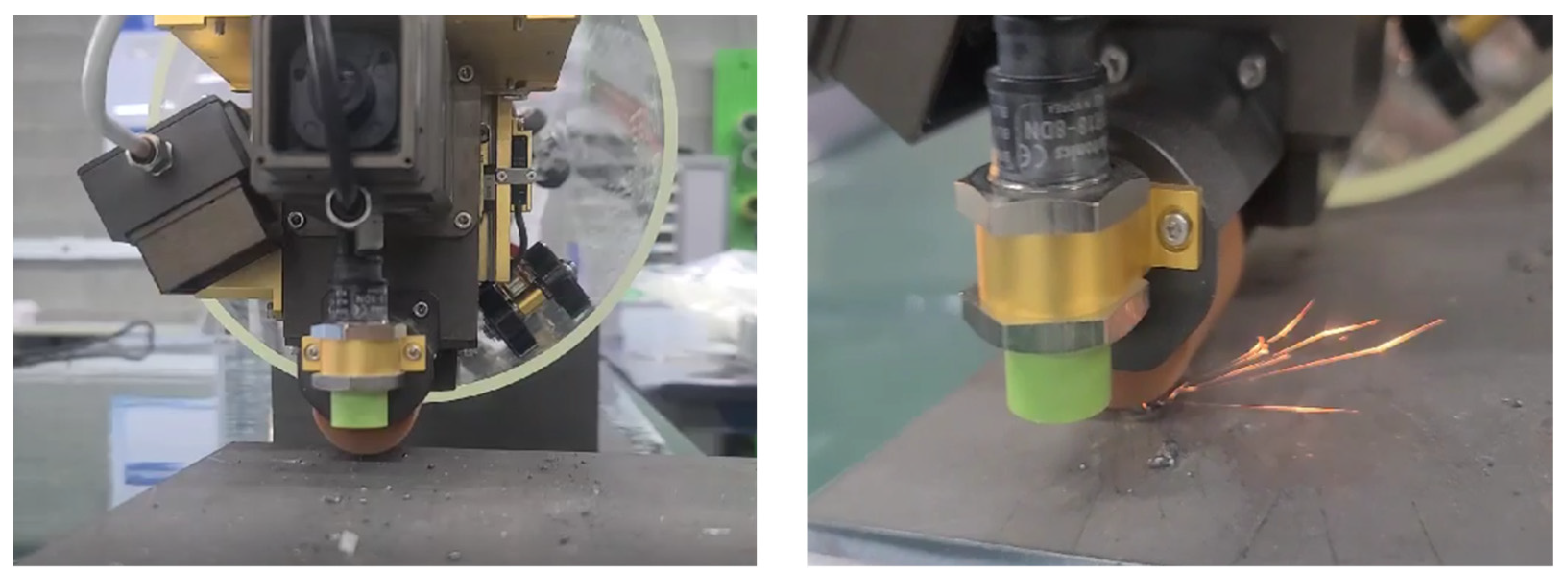
In Figure 16, a spatter was recognized by artificially processing an image the same shape and size as the spatter on the flat plate at the end of the acrylic pipe. Based on information such as the length and angle of the work head, it was possible to confirm that the work head removed the spatter using the grinding tool after checking the correct working distance through the proximity sensor.
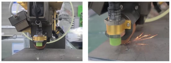
Figure 16.
Removal of spatter using the grinding tool.
The spatter detected inside the pipe was removed, and after removal, the work head should not damage the base material of the pipe. Furthermore, the surface roughness after grinding is important. The surface roughness must be 1.5 Ra (roughness average) or less to ensure the quality required for the inner coating of the pipe in the additional post-processing.
As shown in Figure 17, after detecting and grinding the spatter using the robot, the measurement obtained using the surface-roughness measuring equipment and the measurement after the operator removed the spatter were compared and evaluated to confirm the efficiency of the work performed by the robot.

Figure 17.
Measuring the surface roughness after grinding.
Using the five measurements summarized in Table 7, the average surface roughness was 0.81 Ra. This surface roughness was superior to the existing work results. This confirmed the high work efficiency of the SGR for spatter detection and grinding.

Table 7.
Results of measuring the surface roughness.
6. Conclusions
Due to the COVID-19 pandemic, the global demand for automated systems in production plants has rapidly increased since 2021. Robots are inevitably required in these automated systems. This study focused on the production of ERW pipes. In this study, it was confirmed that the process whereby workers at the piping production site visually check the internal state of the pipe and remove spatter can be automated using a robotic system. Uniform production quality may be ensured by quantitatively improving the surface roughness because of improved spatter detection by the robotic system.
Due to the complex structure that the robot system requires to enable its movement inside small pipes, it is difficult to mount its components to perform various missions inside the pipe. To overcome this issue, a spiral-pattern driving system was proposed and verified in this study. This aligned with the basic purpose of enabling the smooth movement of the SGR inside the pipe. Moreover, spatter detection and removal from inside the pipe were completed successfully.
This study investigated the detection and removal of spatters inside a pipe with a diameter of 15–25 cm. The robotic system comprises a very complex mechanical structure and control system because it is extremely difficult to design a robot that performs all missions inside a pipe with a diameter of just 15 cm or less. In the future, we plan to expand our research to add a driving module that can overcome vertical, horizontal, elbow, and T-branch obstacles in a pipe with a diameter of 15 cm or less as well as a small in-pipe robot that allows the use of detachable devices to perform various missions.
Author Contributions
Conceptualization, S.H. and J.L.; methodology, S.H. and J.B.; software, S.H. and J.B.; validation, S.H., D.S., J.B. and J.L.; formal analysis, S.H.; investigation S.H. and J.B.; resources, S.H., D.S. and J.B.; writing—original draft preparation, S.H. and J.H.; supervision, J.S.; project administration, J.L. and J.S.; funding acquisition, J.L. All authors have read and agreed to the published version of the manuscript.
Funding
This research received no external funding.
Institutional Review Board Statement
Not applicable.
Informed Consent Statement
Not applicable.
Data Availability Statement
Not applicable.
Acknowledgments
The authors would like to thank all researchers of the interactive robotics R&D division in the Korea Institute of Robotics and Technology Convergence (KIRO) and all reviewers for their very helpful comments and suggestions.
Conflicts of Interest
The authors declare no conflict of interest.
References
- Guo, W.; Zhu, Y.; He, X. A robotic grinding motion planning methodology for a novel automatic seam bead grinding robot manipulator. IEEE Access 2020, 8, 75288–75302. [Google Scholar] [CrossRef]
- Sekala, A.; Kost, G.; Banas, W.; Gwiazda, A.; Grabowik, C. Modelling and simulation of robotic production systems. J. Phys. Conf. Ser. 2022, 2198, 012065. [Google Scholar] [CrossRef]
- Ge, J.; Deng, Z.; Li, Z.; Li, W.; Lv, L.; Liu, T. Robot welding seam online grinding system based on laser vision guidance. Int. J. Adv. Manuf. Technol. 2021, 116, 1737–1749. [Google Scholar] [CrossRef]
- Pandiyan, V.; Murugan, P.; Tjahjowidodo, T.; Caesarendra, W.; Manyar, O.M.; Then, D.J.H. In-process virtual verification of weld seam removal in robotic abrasive belt grinding process using deep learning. Robot. Comput.-Integr. Manuf. 2019, 57, 477–487. [Google Scholar] [CrossRef]
- Xu, Z.-L.; Lu, S.; Yang, J.; Feng, Y.-H.; Shen, C.-T. A wheel-type in-pipe robot for grinding weld beads. Adv. Manuf. 2017, 5, 182–190. [Google Scholar] [CrossRef]
- Yabe, S.; Masuta, H.; Lim, H.O. New in-pipe robot capable of coping with various diameters. In Proceedings of the 12th International Conference on Control, Automation and Systems, Jeju, Korea, 17–21 October 2012; pp. 151–156. [Google Scholar]
- Lee, J.Y.; Hong, S.H.; Jeong, M.S.; Suh, J.H.; Chung, G.B.; Han, K.R.; Choi, I.S. Development of pipe cleaning robot for the industry pipe facility. J. Korea Robot. Soc. 2017, 12, 65–77. [Google Scholar] [CrossRef]
- Deepak, B.B.V.L.; Bahubalendruni, M.R.; Biswal, B.B. Development of in-pipe robots for inspection and cleaning tasks: Survey, classification and comparison. Int. J. Intell. Unmanned Syst. 2016, 4, 182–210. [Google Scholar] [CrossRef]
- Islas-García, E.; Ceccarelli, M.; Tapia-Herrera, R.; Torres-SanMiguel, C.R. Pipeline inspection tests using a biomimetic robot. Biomimetics 2021, 6, 17. [Google Scholar] [CrossRef]
- Jeong, B.S.; Lee, J.Y.; Hong, S.H.; Jang, M.W.; Shin, D.H.; Hahm, J.H.; Seo, K.H.; Suh, J.H. Development of the pipe construction robot for rehabilitation work process of the water pipe lines. J. Korea Robot. Soc. 2021, 16, 223–231. [Google Scholar] [CrossRef]
- Jang, M.W.; Lee, J.Y.; Jeong, M.S.; Hong, S.H.; Shin, D.H.; Seo, K.H.; Suh, J.H. Development of spiral driving type pipe inspection robot system for magnetic flux leakage. J. Korean Soc. Precis. Eng. 2022, 39, 603–613. [Google Scholar] [CrossRef]
- Liu, D.; Wang, J.; Lei, T.; Wang, S. Active suspension control with consensus strategy for dynamic posture tracking of wheel-legged robotic systems on uneven surfaces. ISA Trans. 2022; in press. [Google Scholar] [CrossRef] [PubMed]
- Durai, M.; Chi-Chuan, P.; Lan, C.-W.; Chang, H. Analysis of Leakage in a Sustainable Water Pipeline Based on a Magnetic Flux Leakage Technique. Sustainability 2022, 14, 11853. [Google Scholar] [CrossRef]
- Shiomi, D.; Takayama, T. Tapered, Twisted bundled-tube locomotive devices for stepped pipe inspection. Sensors 2022, 22, 4997. [Google Scholar] [CrossRef]
- Li, M.; Du, Z.; Ma, X.; Gao, K.; Dong, W.; Di, Y.; Gao, Y. System design and monitoring method of robot grinding for friction stir weld seam. Appl. Sci. 2020, 10, 2903. [Google Scholar] [CrossRef]
- Lee, C.Y.; Kim, N.H. A study on edge detection using gray-level transformation function. J. Korean Inst. Inf. Commun. Eng. 2015, 19, 2975–2980. [Google Scholar] [CrossRef][Green Version]
- Wu, K.; Sang, H.; Xing, Y.; Lu, Y. Design of wireless in-pipe inspection robot for image acquisition. Ind. Robot 2022. ahead of print. [Google Scholar] [CrossRef]
- Neumann, L.; Čadík, M.; Nemcsics, A. An efficient perception-based adaptive color to gray transformation. In Proceedings of the Third Eurographics Conference on Computational Aesthetics in Graphics, Visualization and Imaging, Alberta Canada, 20–22 June 2007. [Google Scholar]
- Feng, M.-L.; Tan, Y.-P. Adaptive binarization method for document image analysis. In Proceedings of the 2004 IEEE International Conference on Multimedia and Expo, Taipei, Taiwan, 27–30 June 2004; IEEE: New York, NY, USA, 2004; Volume 1. [Google Scholar]
- John, C. A computational approach to edge detection. IEEE Trans. Pattern Anal. Mach. Intell. 1986, PAMI-8, 679–698. [Google Scholar]
- Irwin, S. History and Definition of the Sobel Operator, 2014. World Wide Web 1505. Available online: https://www.scribd.com/document/271811982/History-and-Definition-of-Sobel-Operator (accessed on 4 November 2021).
- Hanno, S. Optimal filters for extended optical flow. In International Workshop on Complex Motion; Springer: Berlin/Heidelberg, Germany, 2004. [Google Scholar]
- Vliet, V.; Lucas, J.; Young, I.; Beckers, G. A nonlinear Laplace operator as edge detector in noisy images. Comput. Vis. Graph. Image Process. 1989, 45, 167–195. [Google Scholar] [CrossRef]
- Prewitt, J.M.S. Object enhancement and extraction. Pict. Process. Psychopictorics 1970, 10, 15–19. [Google Scholar]
- Kim, D.E.; Jin, G.G. Model-based tuning rules of the PID controller using real-coded genetic algorithms. J. Inst. Control. Robot. Syst. 2002, 8, 1056–1060. [Google Scholar]
- Jamali, M.R.; Arami, A.; Hosseini, B.; Moshiri, B.; Lucas, C. Real time emotional control for anti-swing and positioning control of SIMO overhead traveling crane. Int. J. Innov. Comput. Inf. Control. 2008, 4, 2333–2344. [Google Scholar]
Publisher’s Note: MDPI stays neutral with regard to jurisdictional claims in published maps and institutional affiliations. |
© 2022 by the authors. Licensee MDPI, Basel, Switzerland. This article is an open access article distributed under the terms and conditions of the Creative Commons Attribution (CC BY) license (https://creativecommons.org/licenses/by/4.0/).

