1. Introduction
In the last decade, modern roundabouts became popular design solutions for new or reconstructed intersections in urban and suburban areas around the world [
1,
2,
3]. When adequately designed, modern roundabouts provide numerous benefits compared to conventional intersections, such as improved intersection safety and capacity, better vehicle speed management, reduced maintenance costs, and reduced pollution generated by road traffic [
4,
5,
6,
7]. The modern roundabout design process usually consists of a preliminary roundabout geometry design that is followed by performance checks [
8]. These performance checks include:
Investigations of the design vehicle (the least maneuverable vehicle expected to regularly use the intersection surface) and its swept paths (envelopes swept out by the sides of the design vehicle body, or any other part of the structure of the design vehicle);
The definition of the fastest path for the passenger vehicle;
Intersection visibility analyses.
If any of the performance check requirements are not fulfilled, adjustments to the preliminary roundabout geometry are conducted. Once enough iterations have been performed to identify an optimum roundabout geometry, additional detail is added to the design, such as pedestrian and bicycle facilities, vertical design, and traffic control devices [
8]. Previous studies have shown that this time-consuming, iterative process could be replaced with a design based on the results of the design vehicle swept path analysis [
9], according to the following procedure. Firstly, the roundabout outer radius, approach alignments, and the shape of the splitter islands are defined based on the traffic requirements and landscape and space constraints. Then, the swept path analysis for the selected design vehicle is performed for the straight passages, right-turn, and circular movements. Based on the resulting swept paths and selected lateral clearances, the shape of the right carriageway edge and the diameter of the central island (with or without the truck apron) can be defined [
9].
The swept path analysis is conducted by drawing the design vehicle movement trajectories in all possible directions on an intersection blueprint. The conduction of this analysis ensures that the conditions for unobstructed vehicle movement through the intersection are achieved. Nowadays, this analysis can be conducted via the computer simulation of vehicle movement using specialized software such as AutoTURN, AutoTRACK, or Vehicle Tracking. This software can simulate any steering path geometry consisting of circular curves and tangent sections and virtually any vehicle type [
10]. The input parameter necessary for defining the swept path at roundabouts is the design vehicle steering path, i.e., front axle center point path (FACPP) [
8,
9]. FACPP can be drawn “freehand” (i.e., as a manual hand drawing) or with geometric elements such as straight lines and circular arcs. Freehand drawing results in a path that is close to real-world conditions, but it requires considerable engineering experience and skill. Paths composed of straight lines and circular arcs can be drawn by simply offsetting the roundabout outer radius, approach alignments, and the selected shape of the splitter island. The mutual relations of straight lines and circular arcs depend on the direction of the movement of the vehicle through the roundabout: the path for the right turn is composed of an entry branch (straight line) followed by a circular arc and an exit branch (straight line), while the path for the straight passage is composed of entry and exit branches and three consecutive circular arcs in the opposite direction.
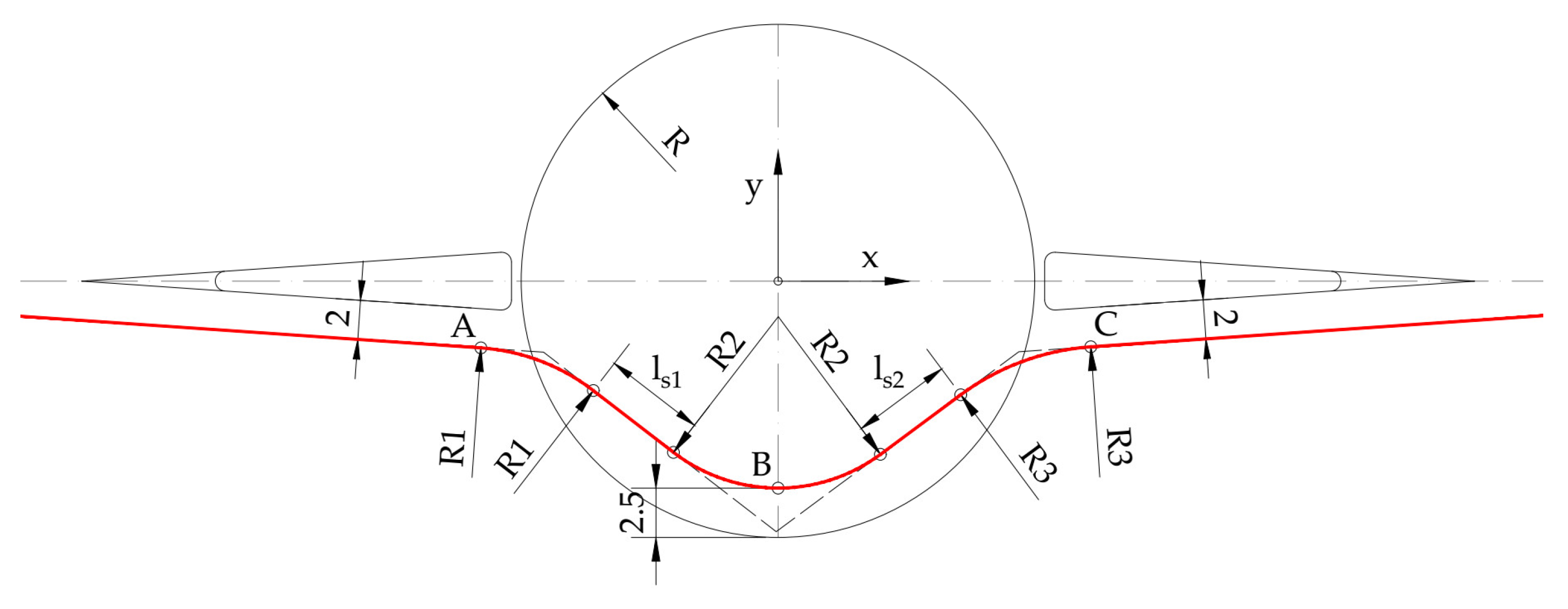
When designing a roundabout based on the results of the design vehicle swept path analysis, parameters for the construction of the design vehicle turning envelope, i.e., right carriageway edge and the width of the circulatory roadway, are not specified. Namely, control parameters for the standard roundabout design process are input parameters in the proposed design process. Therefore, FACPPs need to be constructed solely based on the roundabout outer radius, approach alignments, and the selected shape of the splitter island. Two approaches can be applied when constructing the path for the straight passage. The first approach (hereinafter referred to as A-1) implies the application of short, straight lines (5 to 10 m long) inserted between the adjacent arcs. By applying these short lines, the vehicle path is simulated in the time it takes for the driver to turn the vehicle’s steering wheel when changing the direction of movement, which results in a realistic representation of the vehicle’s movement trajectories [
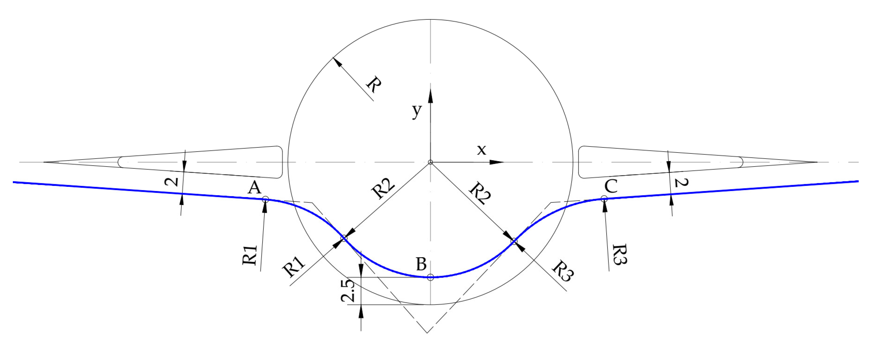
9]. The second approach to the construction of the path (hereinafter referred to as A-2) implies the application of consecutive circular arcs without straight lines inserted between them, following the principles of hairpin bend geometry [
9,
11]. This approach is simpler and faster than the A-1, as fewer geometric elements are required for the construction of the path, and it is in line with the field test results discussed in [
12], which have shown that at a low driving speed (under 20 km/h) the steering gear of long, articulated vehicles can follow a steering path lacking transitions without significant departures.
In this paper, the investigation of the FACPP deviations for paths constructed according to the two aforementioned approaches is presented. The method of the computer simulation of vehicle movement using the Autodesk Vehicle Tracking 2020 computer software was used to define the swept paths. The reliability of chosen software was evaluated and discussed in the paper [
13], where a comparison between the swept path widths determined using a vehicle movement simulation and the swept path widths determined using a precise GNSS device at the test site was given. The results of this investigation showed that from a statistical point of view, these swept path widths did not differ.
For the investigation presented in this paper, a tractor with a semi-trailer was chosen as a design vehicle. This long, articulated vehicle was selected because these types of vehicles face issues while maneuvering the roundabout due to their large turning envelope requirements [
8,
9]. The investigation was conducted on 25 single-lane roundabout schemes with different outer radii (13–25 m), created in AutoCAD software. The investigation aimed to define the applicability of approach A-2 in the design of a right carriageway edge on roundabouts because its construction is simpler and faster than the construction according to approach A-1. The results showed that the A-2 approach is applicable in the design of the right carriageway edge at single-lane roundabouts for chosen design vehicle, but the following should be noted: compared to the A-1 approach, the design vehicle body and chassis turning envelopes derived from the A-2 approach is more offset from the roundabout centers. This results in larger roundabout entry and exit widths as well as the need for larger lateral clearances for entries and exits on roundabouts where heavy pedestrian traffic on sidewalks adjacent to the roundabout is expected. Wider entrances are unfavorable in terms of traffic safety because they enable higher entry speeds [
8,
14]. At the same time, wider roundabout exits enable higher roundabout exit speeds, which could help minimize the likelihood of congestion and crashes at the exits and the potential for trailers to track over the right carriageway edge [
8]. An offset of the left-hand-side design vehicle body and chassis trajectories on the circulatory roadway could have a positive impact on the vehicle path deflection around the central island, which is favorable in terms of vehicle speed reduction [
8,
9,
15,
16].
The paper is organized as follows. Input parameters and methods used in the investigation are presented in
Section 2, and in
Section 3, the results of the investigation are given. In
Section 4, the results are discussed and interpreted from the perspective of the working hypothesis, namely, the applicability of approach A-2 in the design of a right carriageway edge on roundabouts and possible future research directions.
Section 5 concludes the paper.
2. Materials and Methods
Vehicle swept paths can be defined at the test site, by driving a real vehicle in a real traffic situation, but also by applying simulation methods that try to show the movement of the vehicle as close to the real world as possible. The advantages of the computer simulation of design vehicle movement are a simple and fast way of defining different types of vehicles of arbitrary dimensions, setting different vehicle paths, varying turning angles, as well as a fast drawing of the required swept paths [
17,
18]. In this investigation, the method of the computer simulation of vehicle movement using the Autodesk Vehicle Tracking 2020 software was used to define the swept paths. Vehicle Tracking is a third-party computer-aided design (CAD) software released for AUTODESK. It can track the swept paths of selected design vehicles with the help of its algorithm and automate the entire design process.
The applicability of approach A-2 was tested on 25 single-lane roundabout schemes designed in the Autodesk AutoCAD software. These schemes were constructed by varying the outer radius of roundabouts (R) from 13 to 25 m, with a 0.5 m increment. According to previous research given in [
9], these outer radii are commonly used for single-lane roundabouts worldwide. An increment of 0.5 m was chosen to capture the dispersity of the results and to create a sample that is representative, manageable, and easy to present at the same time. Roundabout approach leg axes on these schemes intersect in the center of the roundabout’s outer radius, as shown in
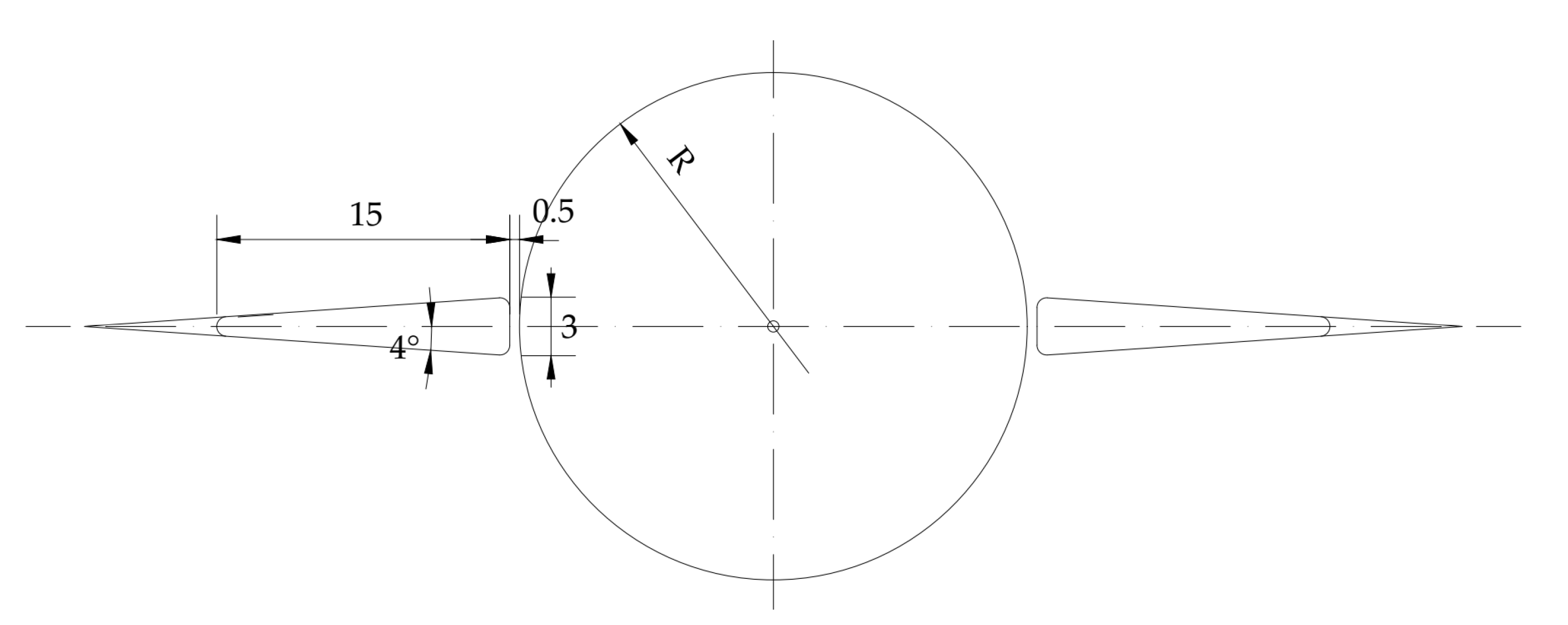
Figure 1. A triangular splitter island, 15 m long and 3 m wide, placed 0.5 m from the roundabout outer radius (R), was selected for this investigation.
Tested FACPPs (shown in
Figure 2 and
Figure 3) were constructed for straight passage through the intersection by applying the following design boundary conditions:
The entry and exit branches on the paths are parallel to the edge of the splitter island and offset by 2 m;
The positions of points A, B, and C on the paths constructed by the A-1 and A-2 approaches are the same for each outer radius, R;
Point B is offset by 2.5 m from the outer radius, R;
Radius R1 is larger or equal to R2 and smaller than R3;
Radius R2 is smaller than R3 by at least 2 m;
Radius R2 on FACPP constructed by A-2 is concentric to outer radius R;
For every FACPP, the lengths of short straight lines (ls1 and ls2) are between 5.0 and 5.5 m.
Constructed FACPP elements and the coordinates of points A, B, and C are given in
Table A1 (
Appendix A).
The type and dimensions of the design vehicle can be determined in the following ways [
9]:
Based on a statistical analysis of data on the presence of vehicles of certain dimensions (wheelbase, overhang length) on the observed section of the road, where the criterion for selecting the design vehicle is the frequency of the occurrence of a certain type of vehicle;
By adopting the design vehicle defined by the appropriate guidelines for the intersection design according to the criterion of the largest turning envelope;
Based on data from the catalog of the most represented vehicle manufacturers on the market, whereby the criterion for selecting the design vehicle is the frequency of the appearance of a certain type and the dimensions of the vehicle.
For the simulations conducted in this investigation, a custom design vehicle was created based on the dimensions given in German guidelines [
19]. German guidelines for the design vehicle lengths were selected for this analysis based on the results of the investigation conducted in [
9]. This investigation included the comparison of turning envelope requirements for the design vehicles given in Austrian, German, and Serbian guidelines and Swiss norms, as well as vehicles whose dimensions were collected from the catalogs of the most represented manufacturers on the European market. The investigation results showed that the vehicle defined in German guidelines has the widest swept path when negotiating a roundabout for a tractor with a semi-trailer. Due to this fact, this design vehicle was applied in the investigation of FACPP deviations presented in this paper, with the following customization: a width of 2.55 m (
Figure 4). The customization of the design vehicle width was made due to the following:
A width of 2.55 m is the actual width of tractors with semi-trailers on the EU road network [
9];
A width of 2.55 m is the maximum permissible width of motor and trailer vehicles prescribed by the European Union Directive [
20].
For both FACPP construction approaches, design vehicle body and chassis envelopes were simulated via Vehicle Tracking software on 25 roundabout schemes. Minimal safety lateral widths of 0.25 m were ensured along the elevated splitter islands in every roundabout scheme, according to the instructions given in [
9,
21]. At the same time, safety lateral widths of at least 0.50 m were ensured along the outer roundabout radius, according to the instructions given in [
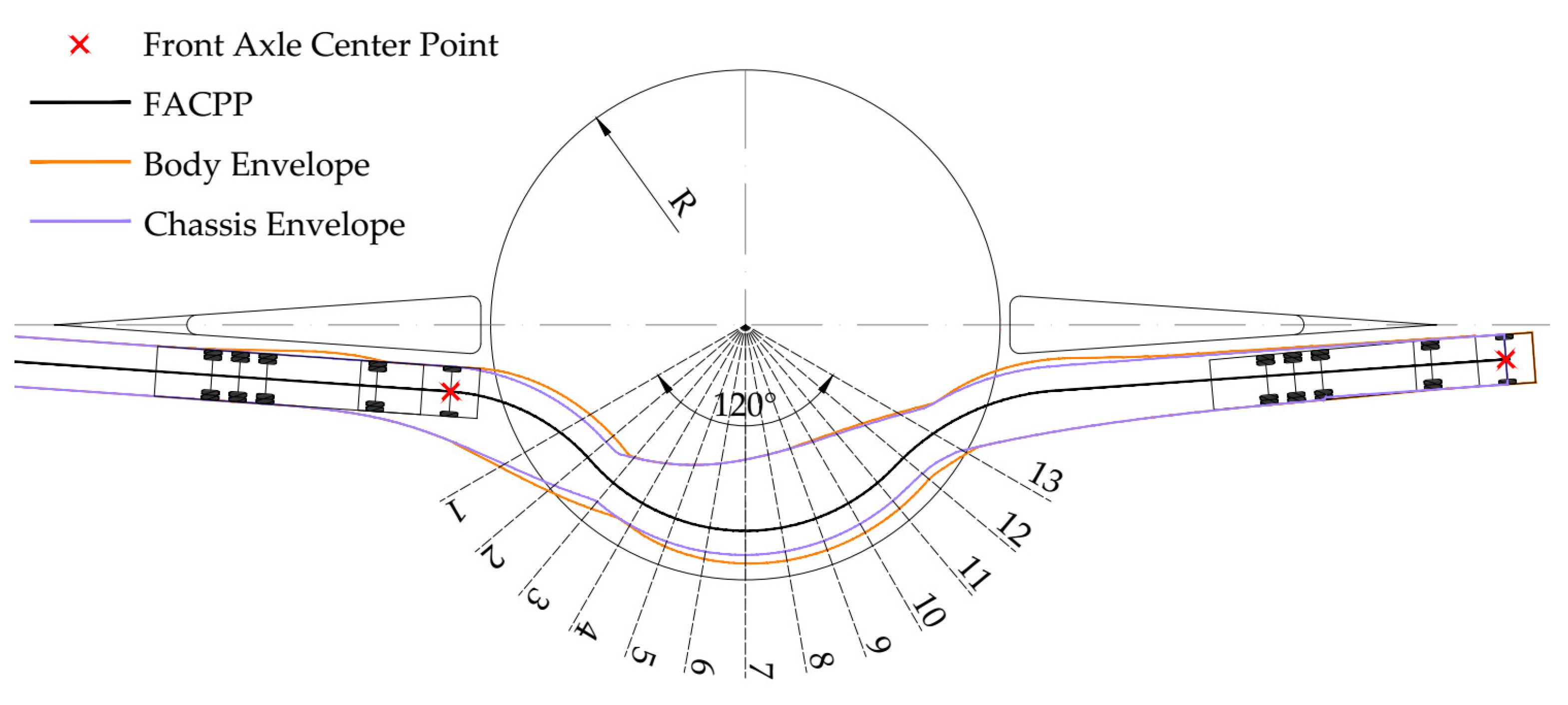
22]. Fifty simulations were conducted, and in total, 200 design vehicle body and chassis envelopes were created. For every R, 13 cross-sections were selected, whose planes intersect at the geometrical center of the roundabout, as shown in
Figure 5. Cross-sections 1–3 intersect the part of the corresponding FACPP on the entry to the circulatory roadway, cross-sections 4–10 intersect the FACPP on the circulatory roadway, and cross-sections 11–13 intersect the FACPP on the exit from the circulatory roadway. Deviations of FACPPs constructed according to the A-2 approach from FACPPs constructed according to the A-1 approach and the deviations of resulting body and chassis envelopes were measured in all 13 cross-sections. Positive deviation values represent the offset of FACPPs constructed according to the A-2 approach from FACPPs constructed according to the A-1 approach (as well as associated envelopes) in the direction from the roundabout center to the right carriageway edge on the roundabout.
Measured deviations were systematized according to roundabout outer radii, R, and cross-sections and presented on diagrams for every trajectory type (FACPP, body, and chassis envelopes). Moreover, the distribution of deviations of the right body and chassis envelopes was calculated.
3. Results
In this section, the results of the investigation, their interpretation, and the conclusions that were drawn are given. The section is divided into two subsections. In the first subsection, diagrams showing the deviations of FACPPs constructed according to the A-2 approach, design vehicle chassis trajectories, and design vehicle body trajectories are presented. In the second subsection, distributions of deviations of the right body and chassis envelopes are presented.
3.1. FACPPs and Trajectories Deviations
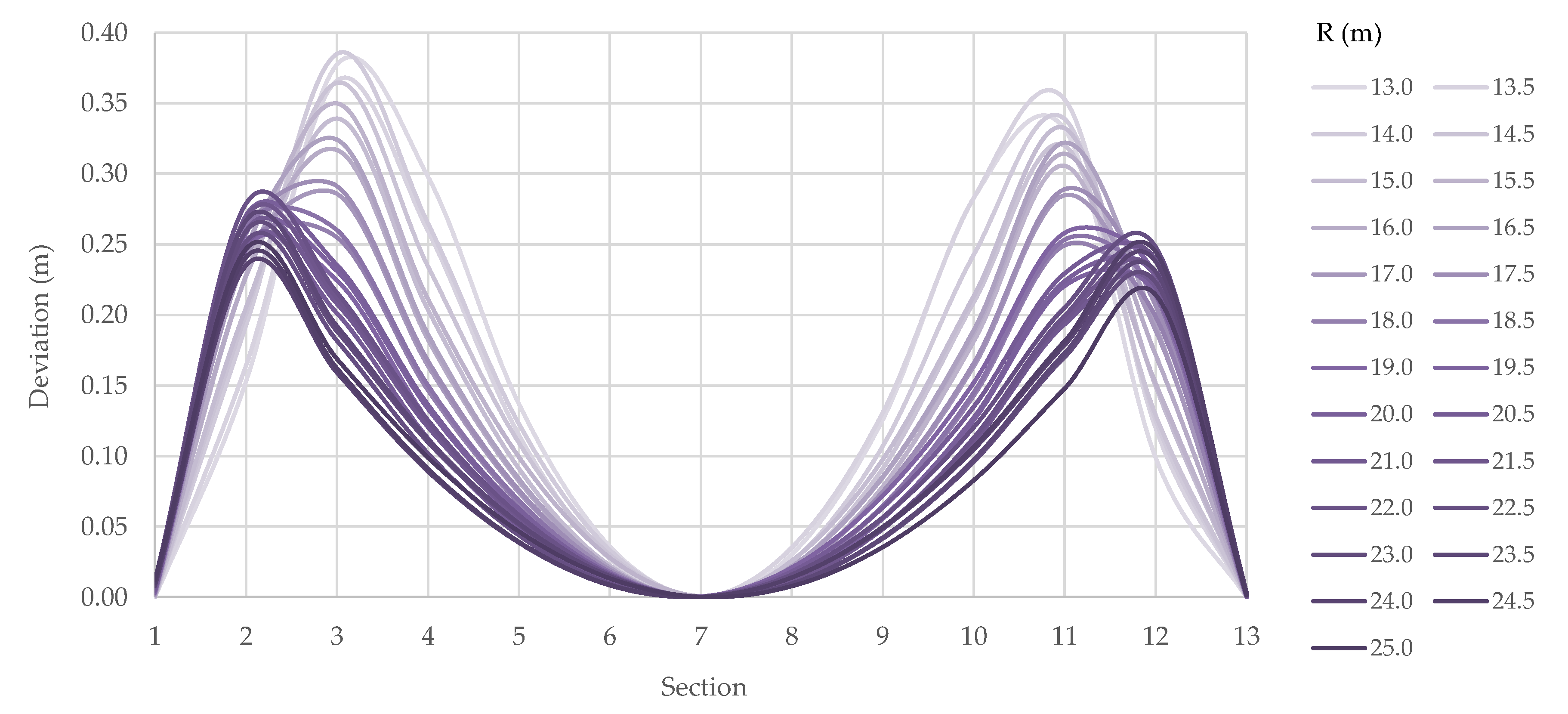
Deviations (in m) of FACPPs constructed according to the A-2 approach from FACPPs constructed according to the A-1 approach for every R and at every cross-section are shown in
Figure 6.
The largest deviations (which do not exceed 0.40 m) for roundabouts with small outer radii are noted at cross-sections 3 and 11 (
Figure 6). With an increase in R, a decrease in deviations is noted, as the cross-sections with maximum deviation become cross-sections closer to the circulatory roadway entry and exit (2 and 12). Deviations under 0.05 m are noted at cross-sections 1, 5–9, and 13. This was expected for cross-section 7 because it transverses point B, which is a common point for analyzed paths. Deviations are proportional to the outer radius R at cross-sections 1, 2, 12, and 13, and inversely proportional at cross-sections 3–11.
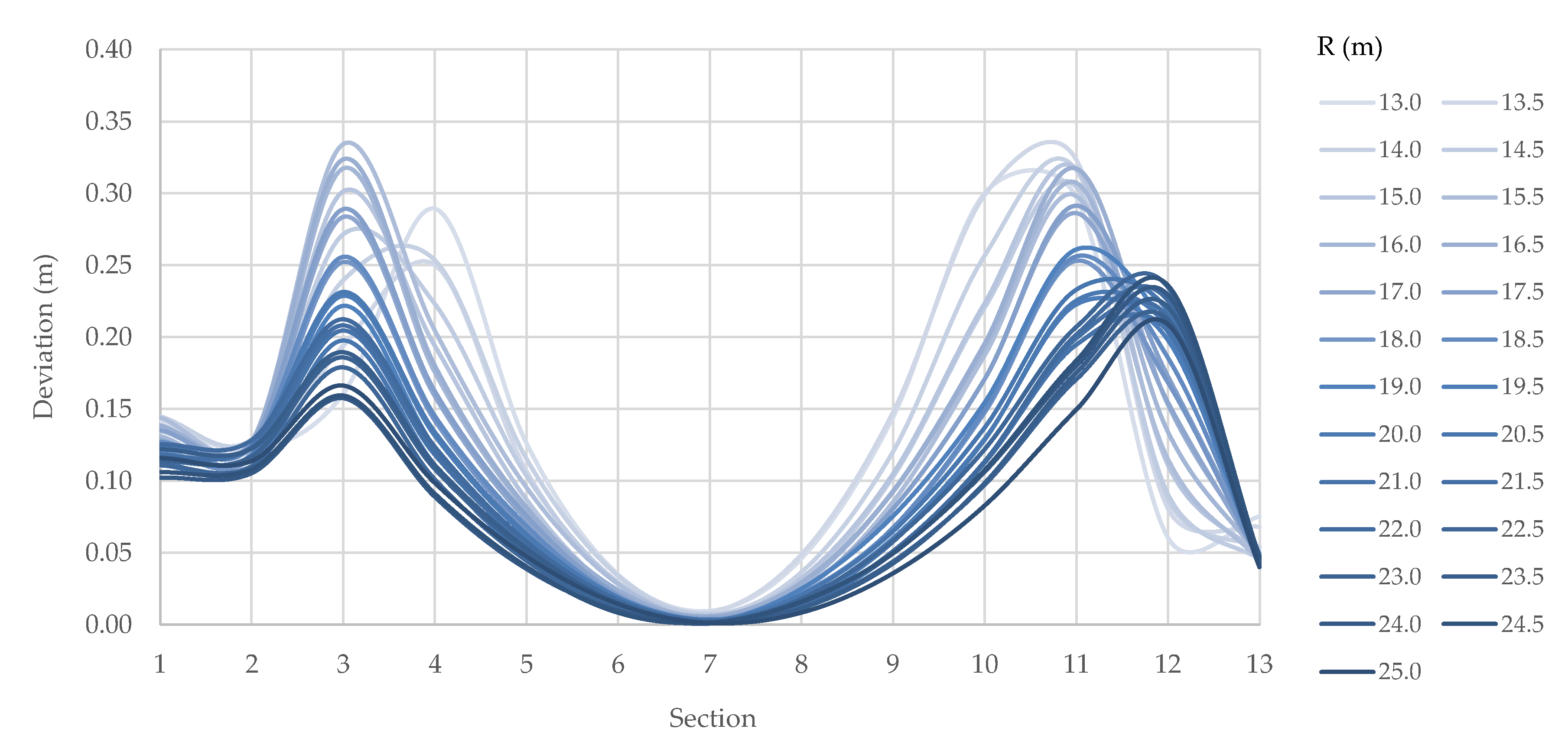
Deviations (in m) of the chassis right-hand-side trajectory for every R and at every cross-section are shown in
Figure 7.
The largest deviations (which do not exceed 0.35 m) for roundabouts with small outer radii are again noted at cross-sections 3 and 11 (
Figure 7). Meanwhile, at roundabouts with outer radii of 13.0, 13.5, and 14.0 m, larger deviations are noted at cross-section 4. With an increase in R, a decrease in deviations is noted. Cross-section 3 remains the one with maximum deviations on the circulatory roadway entry, while cross-section 12 becomes the one with maximum deviations on the circulatory roadway exit. Deviations under 0.05 m are noted at cross-sections 5–9 and 13. This was expected for cross-section 7 because it transverses point B, which is a common point for analyzed paths. Deviations are proportional to the outer radius R at cross-section 12 and inversely proportional at cross-sections 1–11 and 13.
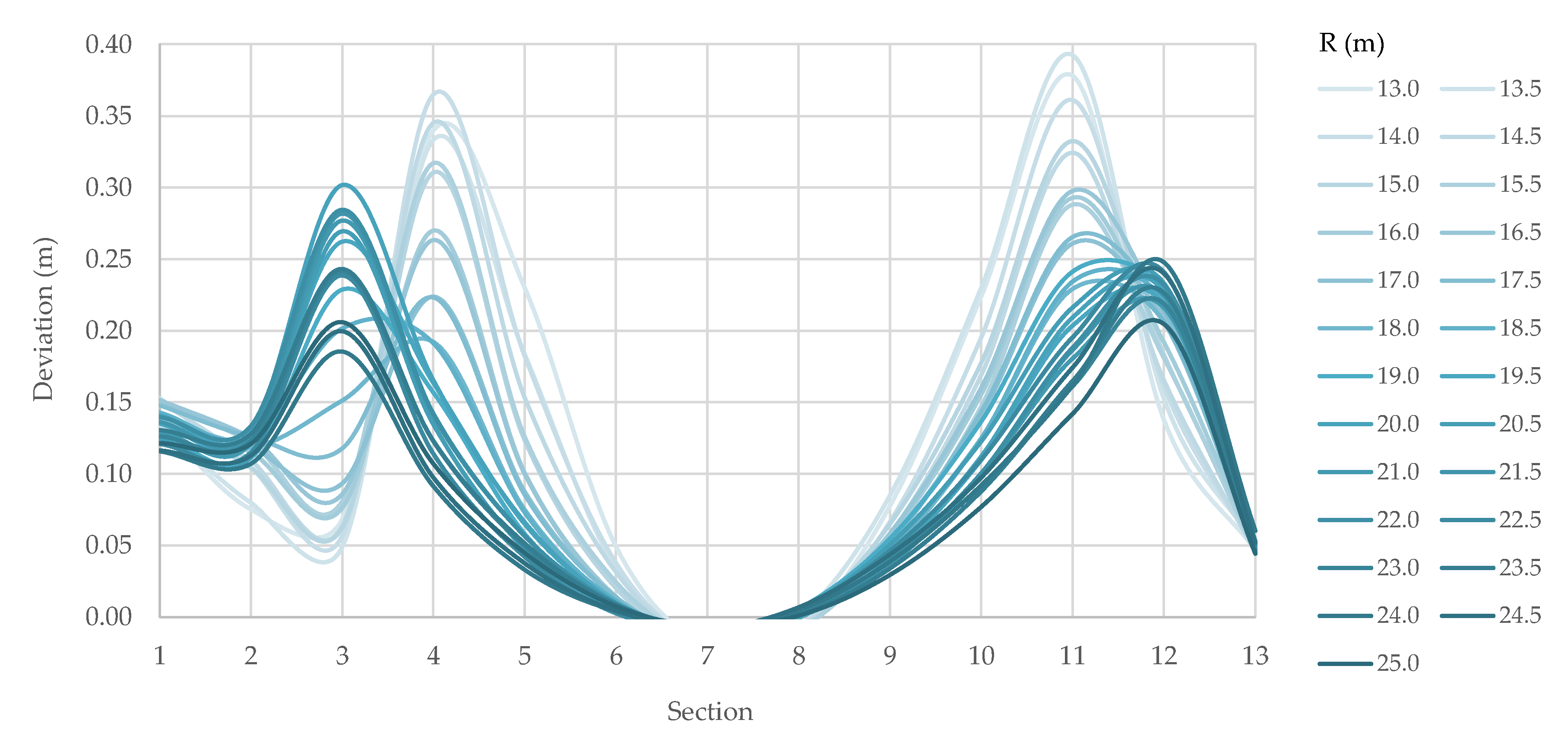
Deviations (in m) of the design vehicle body right-hand-side trajectory for every R and at every cross-section are shown in
Figure 8.
The largest deviations (which do not exceed 0.40 m) are noted at cross-sections 4 and 11 for roundabouts with small outer radii. With an increase in R, a decrease in deviations is noted, as the cross-sections with maximum deviation become cross-sections closer to the circulatory roadway entry and exit (3 and 11). Deviations under 0.05 m are noted at cross-sections 5–9 and 13. This was expected for cross-section 7 because it transverses point B, which is a common point for analyzed paths. Deviations and outer radii, R, are proportional at cross-sections 3, 12, and 13, and inversely proportional at cross-sections 1 and 4–11.
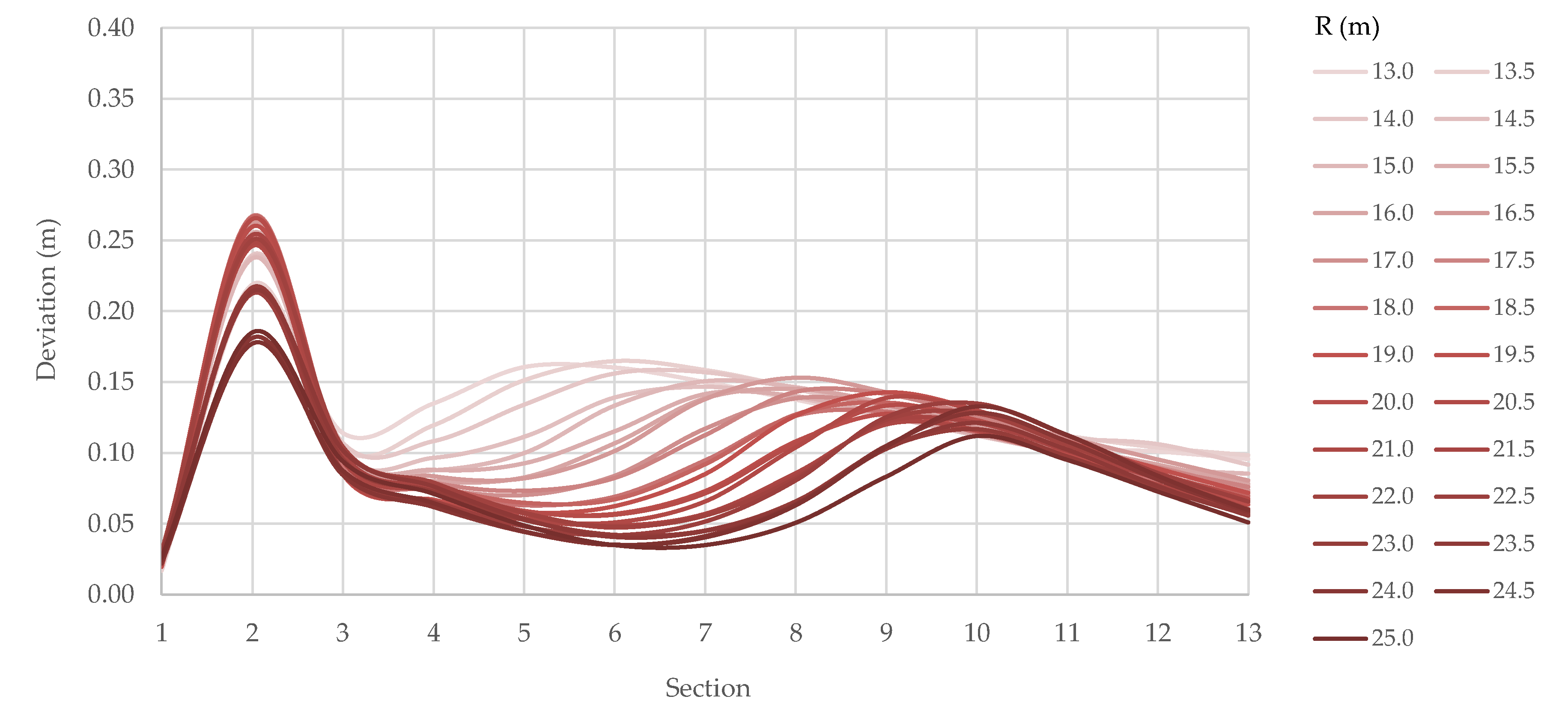
Deviations (in m) of chassis left-hand-side trajectory for every R and at every cross-section are shown in
Figure 9.
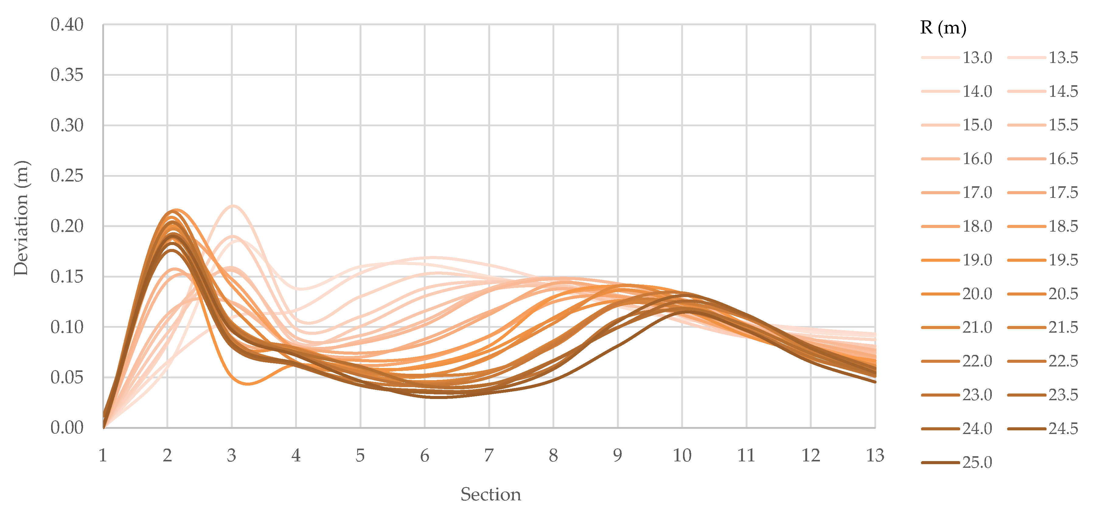
The largest deviations (which do not exceed 0.30 m) are noted at cross-section 2. With an increase in R, a decrease in deviations is noted at cross-sections 3–13. Deviations under 0.05 m are noted at cross-section 1 for all R and on cross-sections 5–7 for larger radii. The biggest influence of R on deviations is noted for cross-sections 3–9, where deviations vary from under 0.05 to over 0.15 m. At the same time, deviations are inversely proportional to the outer radius R at these cross-sections.
Deviations (in m) of the design vehicle body left-hand-side trajectory for every R and at every cross-section are shown in
Figure 10.
The largest deviations (which do not exceed 0.25 m) are noted at cross-sections 2 (for larger R) and 3 (for R between 13.0 and 14.5 m). Deviations are inversely proportional to the outer radius, R, at cross-sections 3–13. Deviations under 0.05 m are noted at cross-section 1 for all R and on cross-sections 5–7 for larger radii. The biggest influence of R on deviations is noted for cross-sections 3–9, where deviations vary from under 0.05 to over 0.15 m. At the same time, the deviations are inversely proportional to the outer radius R at these cross-sections.
Based on the presented results, the following conclusions can be drawn.
Generally, deviations are inversely proportional to the outer radius, R.
As a rule, the shape of deviation diagrams for right-hand-side trajectories follows the shape of deviation diagrams for FACPP, except at cross-sections on the circulatory roadway entry (1–3).
As a rule, the shape of deviation diagrams for left-hand-side trajectories follows the shape of deviation diagrams for FACPP only at cross-sections on the circulatory roadway entry (1–3).
Right-hand-side trajectory deviations are larger than left-hand-side trajectory deviations.
The largest deviations of the right-hand-side trajectories are noted at cross-sections on the circulatory roadway entry and exit (1–3 and 11–13).
3.2. Distribution of Deviation for Right-Hand-Side Trajectories
For results interpretation purposes, the following qualitative groups of measured deviations were formed: “small deviations” are deviations ranging from 0.00 to 0.15 m, “medium deviations” are deviations ranging from 0.15 to 0.25 m, and “large deviations” are deviations over 0.25 m. Distributions of deviations of the right-hand-side body and chassis envelopes are presented in
Figure 11,
Figure 12,
Figure 13 and
Figure 14.
When the distribution of all 650 measured deviations of right-hand-side trajectories (
Figure 11) is observed, it can be concluded that over 70% of these deviations belong to the group “small deviations”, and 20% of the measured deviations of right-hand-side trajectories belong to the group “medium deviations”. “Large deviations” were not recorded for roundabouts with an outer radius over 22.0 m, and “medium deviations” were recorded on all investigated roundabout schemes.
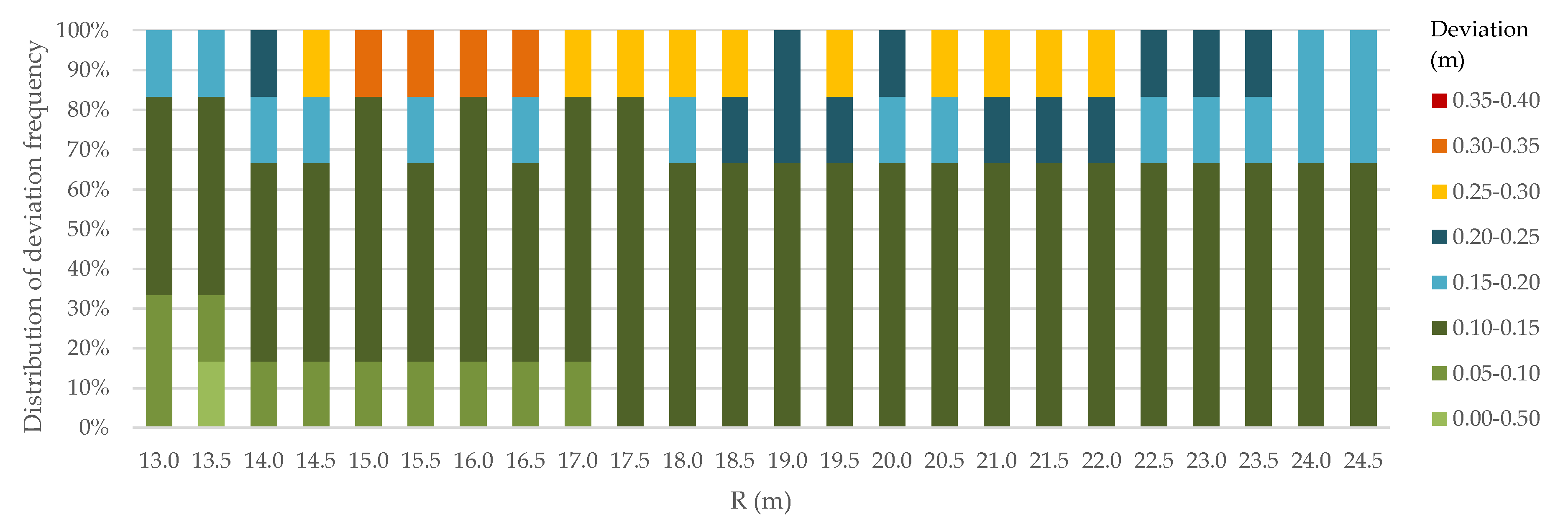
When the distribution of all 150 measured deviations of right-hand-side trajectories on cross-sections 1–3 (
Figure 12) is observed, it can be concluded that over 70% of these deviations belong to the group “small deviations” (with 63% of deviations that are in the upper third of the group range, from 0.10 to 0.15 m). Again, 20% of measured deviations of right-hand-side trajectories on cross-sections 1–3 belong to the group “medium deviations”. “Large deviations” were not recorded for roundabouts with an outer radius under 14.5 m and over 22.0 m. Deviations of up to 0.40 m were not recorded. Deviations of up to 0.35 m were recorded on roundabouts with an outer radius smaller than 17.0 m. Deviations of up to 0.30 m were recorded on roundabouts with an outer radius smaller than 22.5 m. “Medium deviations” were recorded on all investigated roundabout schemes.
When the distribution of all 350 measured deviations of right-hand-side trajectories on cross sections 4–10 (
Figure 13) is observed, it can be concluded that 85% of these deviations belong to the group “small deviations”, and 10% of the measured deviations of right-hand-side trajectories on cross-sections 4–10 belong to the group “medium deviations”. “Large deviations” were not recorded for roundabouts with an outer radius over 16.5 m. Deviations of up to 0.40 m were recorded on roundabouts with an outer radius smaller than 14.5 m. Deviations of up to 0.35 m were recorded on roundabouts with an outer radius smaller than 16.0 m. Deviations of up to 0.30 m were recorded on roundabouts with an outer radius smaller than 17.0 m. “Medium deviations” were not recorded for roundabouts with an outer radius over 20.0 m.
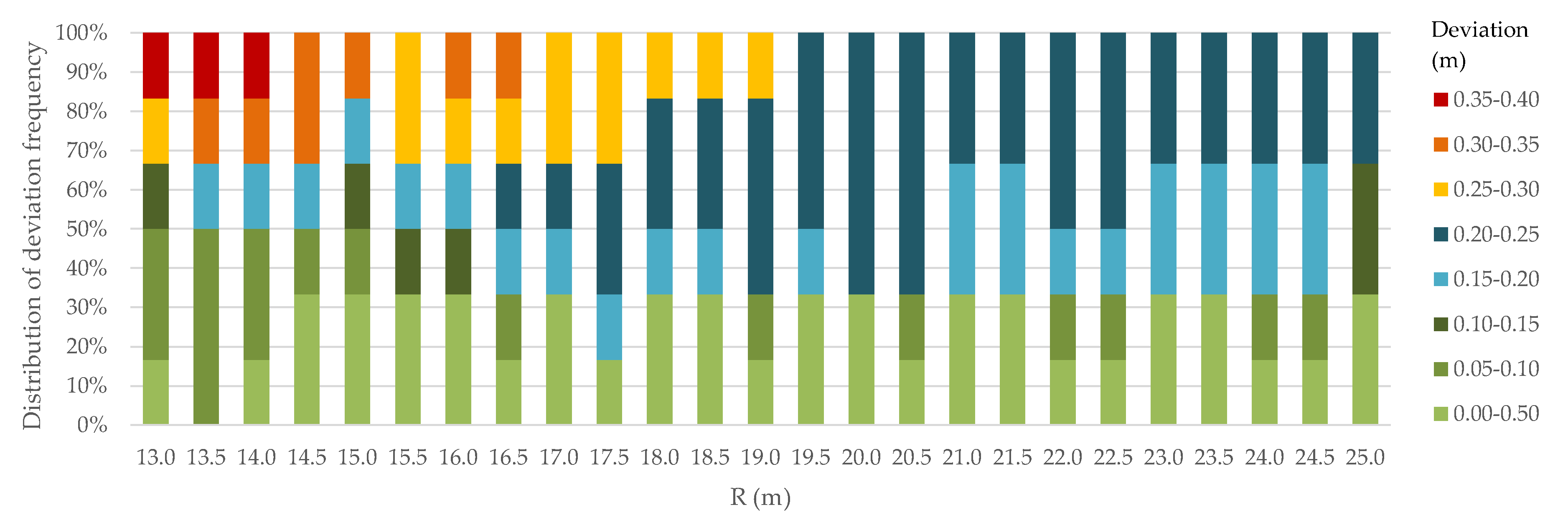
When the distribution of all 150 measured deviations of right-hand-side trajectories on cross sections 11–13 (
Figure 14) is observed, it can be concluded that 40% of these deviations belong to the group “small deviations”, and 45% of the measured deviations of right-hand-side trajectories on cross sections 11–13 belong to the group “medium deviations”. “Large deviations” were not recorded for roundabouts with an outer radius over 19.0 m. Deviations of up to 0.40 m were recorded on roundabouts with an outer radius smaller than 14.5 m. Deviations of up to 0.35 m were recorded on roundabouts with an outer radius smaller than 17.0 m. Deviations of up to 0.30 m were recorded on roundabouts with an outer radius smaller than 19.5 m. “Medium deviations” were recorded on all investigated roundabout schemes.
Based on the presented results, the following conclusions can be drawn.
The most frequent “small deviations” (85%) were recorded at cross-sections 4–10, which intersect the part of the corresponding FACPP on the roundabout circulatory roadway.
The most frequent “medium deviations” (40%) were recorded at cross-sections 11–13, which intersect the part of the corresponding FACPP on the circulatory roadway exit.
The most frequent “large deviations” (15%) were recorded at cross-sections 11–13 which intersect the part of the corresponding FACPP on the circulatory roadway exit.
“Large deviations” were not recorded at cross-sections on circulatory roadway entries (1–3) for outer radii under 14.5 m and over 22.0 m, cross-sections on the circulatory roadway (4–10) for outer radii over 16.5 m, and cross-sections on circulatory roadway exit (11–13) for outer radii over 19.0 m.
Deviations are proportional to the outer radii for cross-sections on the circulatory roadway (4–10) and circulatory roadway exit (11–13).
For cross-sections on the circulatory roadway entry, no relationship between the deviations and outer radii is noted.
Deviations larger than 0.30 m were not recorded at cross-sections 1–3 for outer radii larger than 17.0 m, cross-sections 4–10 for outer radii larger than 16.0 m, and cross-sections 11–13 for outer radii larger than 17.0 m.
4. Discussion
As kinematic and dynamic requirements lose their importance due to low driving speed on roundabouts, a prerequisite for quality roundabout design becomes the definition of the design vehicle movement geometry and its turning envelopes [
9]. According to the results of the investigation presented in this paper, the design vehicle tractor with a semi-trailer chassis turning envelopes derived from the A-2 approach were more offset from the roundabout centers when compared to the path constructed via the A-1 approach. Namely, 72% of right-hand-side path and resulting right-hand-side design vehicle body and chassis turning envelope deviations were between 0.00 and 0.15 m, 27% were over 0.15 m, and 7% were over 0.25 m. Deviation frequency for deviations over 0.25 m is inversely proportional to the outer roundabout radius. This shows that, in general, the A-2 approach results in wider entrances and exits compared to the A-1 approach. Wide entrances are unfavorable in terms of traffic safety as they enable higher entry speeds, especially for personal vehicles [
8,
14]. On the other hand, wide exits enable higher roundabout exit speeds and could help minimize the likelihood of congestion and crashes at the exits. Wide exits may also be desirable in areas with high truck volumes to provide ease of navigation for trucks and reduce the potential for trailers to track over the outside curb. However, at urban intersections, there is a need to maintain lower speeds through the pedestrian crossing on roundabout exits [
8].
The deviations of the left-hand-side design vehicle body and chassis trajectories on the circulatory roadway (cross-sections 4–10) were small, mostly between 0.05 and 0.15 m. Nevertheless, this means that approach A-2 provides an opportunity to design a central island with a larger radius than approach A-1. A central island with a larger radius could have a positive impact on traffic safety. Namely, it provides for greater vehicle path deflection, and consequently, vehicle speed reduction [
8,
16]. Speed reduction is a benefit of a well-designed roundabout that usually results in homogeneous driver behaviors and increased traffic safety [
15].
The investigation results showed that allowances larger than 0.30 m should be added for lateral clearances when utilizing the A-2 approach for roundabouts with outer radii smaller than 17.0 m. Namely, on these roundabout schemes, deviations larger than 0.30 m were noted for the design vehicle body and chassis envelopes at circulatory roadway entry and exit cross-sections. This could be of concern if approach A-2 is used for roundabouts in locations where heavy pedestrian traffic on sidewalks adjacent to the roundabout is expected, i.e., for urban intersections, as pedestrians could come in conflict with passing vehicle body. In general, in urban areas, the design of roundabouts should be carefully conducted by considering the presence of these vulnerable users [
4,
16].
The limitations of this investigation are as follows. The investigation was conducted for single-lane roundabouts whose approach leg axes are placed on the straight that passes through the geometrical center of the roundabout (center of the circular island). In the real world, this ideal position of the approach leg axes is sometimes not possible to achieve due to the spatial constraints, as well as the requested number and the alignment of the approach legs. This results in different locations of points A, B, and C on the FACPPs for straight passage due to the offset of the approach leg axes from the center of the circular island and different angles between the approach legs. Furthermore, long vehicles that pose a challenge in roundabout design are not only tractors with semi-trailers, but also three-axle buses, which are not included in this investigation. Another issue that should be addressed is the influence of the approach A-2 application on personal vehicle speed. Therefore, to investigate the potential effect of these factors, future research should include the investigation of the turning envelopes of three-axle buses, the investigation of different approach alignments, and the investigation of the fastest paths for personal vehicles. As the development of CAD applications has made the construction of cubic splines (piecewise polynomials of the third degree with function values and second derivatives that agree at the nodes where they join) easier, this type of FACPP should also be investigated in future research. The spline path mimics the real-world vehicle path more faithfully than the paths constructed by approaches A-1 and A-2 [
23,
24]. At the same time, its construction does not require significant engineering experience and skill. When constructing the path by this method, nodes must result in a spline curve tangent with the prescribed minimum clearances [
25,
26].
5. Conclusions
The investigation presented in this paper focuses on one of the elementary issues in transportation engineering: whether the traffic infrastructure will provide required traffic safety, i.e., how steering path geometry impacts turning movements for long, articulated vehicles such as a tractor with a semi-trailer. Roundabouts are potentially hazardous locations due to the large turning envelopes required by long, articulated vehicles. When designing a roundabout based on the results of the design vehicle swept path analysis, the parameters for the construction of the design vehicle turning envelope are not specified. Therefore, FACPPs need to be constructed solely based on the roundabout outer radius, approach alignments, and the selected shape of the splitter island. Two approaches can be applied when constructing the path for the straight passage. The first one (A-1) implies the application of short, straight lines inserted between the adjacent arcs. The second one (A-2), which is faster and simpler to use, implies the application of the principles of hairpin bend geometry. In this paper, the investigation of the deviations for paths constructed according to these approaches was presented. The results of the investigation can help to identify an adequate vehicle path construction approach and the range and combination of path geometric elements needed for the simulation of design vehicles through movements at single-lane roundabouts with outer radii varying from 13 to 25 m.
The investigation results showed that the front axle center point paths for straight passage through the roundabout constructed following the principles of hairpin bend geometry, i.e., with consecutive circular arcs, is applicable in the design of the right carriageway edge in single-lane roundabouts for a design vehicle tractor with a semi-trailer, as only 7% of right-hand-side path and resulting right-hand-side design vehicle body and chassis turning envelope deviations exceeded 0.25 m. At the same time, the offset of left-hand-side design vehicle trajectories on the circulatory roadway (which was mostly between 0.05 and 0.15 m) could have a positive impact on the deflection around the central island. Nevertheless, the following should be remembered when utilizing this approach: when compared to the path with short, straight lines inserted between the adjacent arcs, the design vehicle body and chassis turning envelopes are more offset from the roundabout centers. This could result in the following:
Up to 0.35 m wider roundabout entrances, which is unfavorable in terms of traffic safety as it enables higher roundabout entry speed;
Up to a 0.15 m larger central island radius, resulting in larger vehicle path deflection around the central island, which is favorable in terms of speed reduction;
Up to 0.40 m wider roundabout exits, which enable higher roundabout exit speed and could help minimize the likelihood of congestion and crashes at the exits and the potential for trailers to track over the right carriageway edge;
The need for lateral clearances larger than 0.30 m on roundabout entries and exits when the roundabout outer radius is smaller than 17.0 m.
