Article

An Under-Sampling Array Signal Processing Method Based on Improved Hadamard Matrix

1
Department of Automation, Hangzhou Dianzi University, Xiasha Higher Education Zone, Hangzhou 310018, China
2
Department of Naval Architecture, Ocean and Civil Engineering, Shanghai Jiao Tong University, Shanghai 200240, China
*
Author to whom correspondence should be addressed.
Appl. Sci. 2022, 12(21), 10769; https://doi.org/10.3390/app122110769
Submission received: 24 September 2022 / Revised: 17 October 2022 / Accepted: 20 October 2022 / Published: 24 October 2022

Abstract

:
The compressive sensing method is an effective way of under-sampling array signal processing, and the measurement matrix is a key technology of compressive sensing processing, which is of decisive significance to improve the performance of under-sampling array signal processing. In this paper, an under-sampling array signal processing method based on an improved Hadamard measurement matrix was proposed. This method improved the construction of the measurement matrix by a compressing zero method capable of reducing the redundant data, enhancing the non-correlation between columns, improving the RIP condition, and improving the performance of the compressive sensing method. The performance was verified by simulation and real data from the lake, and the results showed that the method proposed in this paper has obvious performance advantages compared with the Toeplitz Circular Matrix, the m-sequence-based matrix, and the partial Hadamard matrix under the same conditions.

1. Introduction

Array signal processing [1] plays an important role in many aspects of applications such as radar, sonar, communication, and so on. Direction of arrival (DOA) estimation, as an important branch of array signal processing, has become a hot research topic. There are three main types of DOA estimation algorithms [2]: beam scanning algorithm; high-resolution methods; and sparse signal-processing algorithm. Conventional beamforming (CBF) is the most widely used beam scanning algorithm, it has high robustness against signal mismatch [3], but the resolution of the algorithm is limited by the Rayleigh limit [4], which means that it has wide beam width. Typical high-resolution methods include minimum variance distortionless response (MVDR) [5], multiple signal classification (MUSIC) [6], DOA estimation based on eigenspace (ES-DOA) [7], and estimation signal parameter via rotational invariance techniques (ESPRIT), etc. These algorithms mainly rely on the statistical characteristics of the signal received by the array to complete the estimation of the direction of arrival of the signal. Therefore, to obtain higher estimation accuracy, more hardware circuits are often required to obtain a large amount of measurement data, and a large amount of calculation time is required. Compressive sensing (CS) [8], a sparse signal-processing algorithm, can obtain all the information of the signal using less signal observation data. Its appearance improves the performance of high-resolution DOA estimation under low sampling conditions. Compressive beamforming methods have higher angular resolution than traditional high-resolution beamforming methods [9].Furthermore, the case where the number of sources is larger than the number of physical sensors has been shown to be much more difficult in the DOA estimation problems studied [10,11]. For this uncertain DOA estimation task, various sparse array structures have been proposed as possible solutions [12,13], such as the nested array [14,15] and coprime array [16] and their various extensions, for both second-order and fourth-order problems.
In recent years, CS has received widespread attention, and the measurement matrix is an important technology to implement an under-sampling array signal processing. Reference [17] proposed a compressive sampling array (CSA) using a random measurement matrix, such as the Gaussian, or Bernoulli matrix, to compress large-size array elements into small-size array elements and estimated the angle spectrum of uncorrelated sources by the CSA-MVDR method. Reference [18] proposed a novel compressive sensing beamforming (CSB) algorithm based on CSA for DOA estimation. Reference [19] investigated DOA estimation by compressive sampling array and compressive beamformer algorithm and analyzed their advantages and limitations. DOA estimation of coherent sources was addressed in reference [20] by compressing the array in the spatial domain, but the effect of estimation could be improved. Reference [21] proposed the approach of CS array DOA estimation based on eigenspace (CSA-ES-DOA), and it used a very small number of measurements to resolve the DOA estimation of the coherent signals and two closely adjacent signals. The measurement matrix plays a vital role in CSA, and the random matrix is difficult in hardware implementation, so the deterministic matrix based on m-sequence [22], the sequential partial Hadamard matrix [23], the deterministic binary block diagonal matrix [24], the Polynomial deterministic matrix [25] and Toeplitz and circulant matrices [26] were researched.
The above deterministic measurement matrix can be realized by hardware, but they have certain conditions and limitations, and the reconstruction resolution after compressing is not ideal enough, especially at a small compression ratio. Therefore, this paper proposed a new deterministic measurement matrix based on a partial Hadamard matrix and used it to sample and compress the received array signal to obtain target-bearing information through the relevant adaptive reconstruction algorithm. The method can enhance the column-to-column non-correlation in the measurement matrix and improve its processing speed and reconstruction estimation performance. The performance was verified by simulation and real data on the lake.

2. Array Signal Processing Model Based on Compressive Sensing

According to the theory of compressive sensing, the reconstruction of the sparse signal mainly includes the following three steps: the first is the sparse transformation of the signal, that is, by selecting a suitable sparse dictionary, and according to this dictionary, the coordinates of the original signal with sparsity can satisfy the sparse structure, during the processing of the space array signal, the number of signals received by the array often only accounts for a few in the entire airspace grid, so it can be considered that the target signal in the airspace grid is sparse; the second step is the structure of the observation matrix, after constructing an observation matrix that is not related to the sparse dictionary, the high-dimensional sparse signal is reduced to the low-dimensional signal that is convenient for the transmission to complete the sample of the sparse signal; and the last step is the sparse reconstruction of the transmitted signal, that is, the reconstruction of the original signal is completed by using the low-dimensional signal obtained by transmission, so as to realize the purpose of estimating the direction of arrival of the wave. This section will introduce the compressive sensing model of the array signal processing based on the above steps.

2.1. Array Received Signal and Its Sparsity

2.1.1. Narrowband Array Received Signal

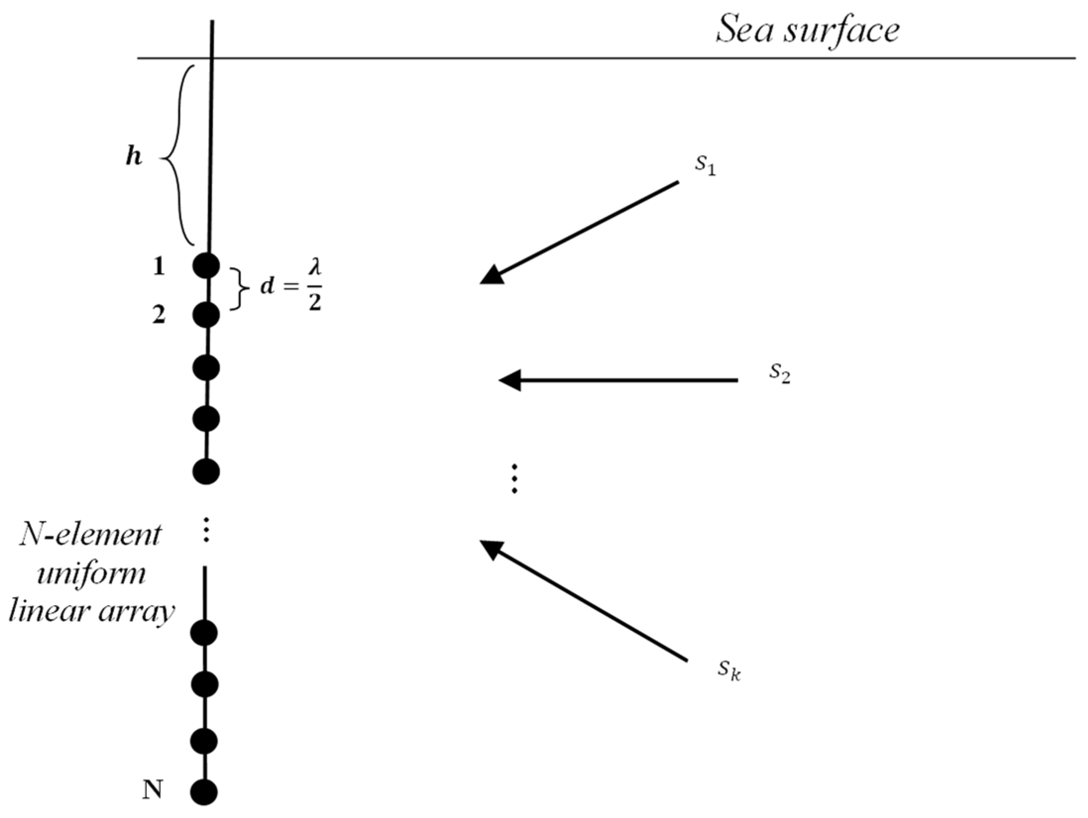
In this work, we assume there are N acoustic sensors the spacing is d in a uniform linear array (ULA) and K narrowband underwater sound sources or targets in the far field of the array, as in Figure 1. In addition, there is no mutual coupling between the array sensors, and the number of the sources or targets is less than the number of array sensors [27].
According to the above assumptions, then the array received signal of the nth sensor can be written as:
x n ( t ) = k = 1 K s k ( t ) e j 2 π f 0 d ( n 1 ) cos ( θ k ) c + v n ( t ) ,     n = 1 , 2 , , N ,
where s k ( t ) is the signal emitted by the kth source; v n ( t ) is the nth sensors receiving the environmental noise; f 0 represents the narrowband frequency; c represents the sound speed; and the t = 1 , 2 , L , where t represents the discrete sampling time.
Then we discretize the potential space so that the source is sparse in spatial [28]. The space of interest is divided as P grid points, as in Figure 2, i.e., θ [ 0 ° , 180 ° ] is divided as { θ 1 , , θ p , , θ P } with P K , every point is viewed as a potential source. Therefore, the Equation (1) can be rewritten as:
X ( t ) = A S ( t ) + v ( t ) ,
where X ( t ) is the signal data of size N × L received by the ULA; v ( t ) is the environmental noise data of size N × L received by the ULA; S ( t ) is K sparse underwater target echo signal amplitude information of size P × L ; A is the array manifold matrix of size N × P under P gridding, i.e., A = [ a ( θ 1 ) , a ( θ 2 ) , , a ( θ P ) ] , where a ( θ p ) is the steer vector and it can be written as:
( θ p ) = [ 1 , e j ( 2 π f c × d × c o s θ p ) , , e j ( 2 π f c × ( n 1 ) × d × c o s θ p ) ] T ,   p = 1 , 2 , , P .
As shown in Figure 2, the azimuth is divided into P grids by gridding, it is assumed that the P grids are sufficiently density, so that the real sources or targets can be viewed as being reasonably close to some of those grid points, where the solid circles represent the real targets, and the hollow circles represent the grid points without the real targets. The unknown vector S represents the source amplitudes at all P grid points. The pth entry of is equal to zero if there are no sources or targets at θ p , otherwise, it is non-zero. Therefore, it can be considered that S is sparse in spatial distribution.

2.1.2. Wideband Array Received Signal

The wideband underwater sound sources share the same received model for all narrowbands of different frequencies, so the wideband observation model can be treated as separated narrowband problems. We assume that they are independent and uncorrelated between different frequency bands in this paper. Therefore, the frequency domain form of the ULA received signal X ( f ) as the superposition of G narrowband signals, Equation (1) can be written as:
x n ( f ) = k = 1 K s k ( f ) e j 2 π f d ( n 1 ) cos ( θ k ) c + v n ( f ) ,   n = 1 , 2 , , N ,
We divide the frequency domain array element observation signal into G narrowband at different frequencies in the bandwidth B, therefore, the wideband observation model of the ULA received signal for the gth narrowband in the frequency domain can be expressed by Equation (2) as [29]:
X ( f g ) = A ( f g , θ ) S ( f g ) + V ( f g ) , ( g = 1 , 2 , , G ) ,
where f g represents the center frequency of the gth narrowband signal, V ( f g ) = [ V 1 ( f g ) , V 2 ( f g ) , , V N ( f g ) ] T is the jth narrowband component of the noise transformed by DFT, X ( f g ) = [ X 1 ( f g ) , X 2 ( f g ) , , X N ( f g ) ] T is the gth narrowband component of the ULA received signal transformed by DFT, S ( f g ) = [ S 1 ( f g ) , S 2 ( f g ) , , S P ( f g ) ] T is the amplitude information of targets at the gth narrowband component, A ( f g , θ ) = [ a ( f g , θ 1 ) , a ( f g , θ 2 ) , , a ( f g , θ P ) ] is the array manifold matrix at frequency f g , θ is the set of the all potential bearing of the K targets, a ( f g , θ p ) is the array response vector or bearing vector of the target which is from bearing θ p as incident frequency f g , and it can be shown as:
a ( f g , θ p ) = [ 1 , e j ( 2 π f g c × d × c o s θ p ) , , e j ( 2 π f g c × ( n 1 ) × d × c o s θ p ) ] T , ( p = 1 , 2 , , P ) .
It can be seen from the above that the target is sparse under the divided grid, and when M K l o g ( N ) is satisfied [21], the array data after compressive sampling can contain the essential information of the target signals and complete the detection estimation of K targets with high probability.

2.2. Compression of The Array Signal

We combine compressed sensing into the array signal in the following. By compressive sampling matrix Φ , the N-element linear array data X is compressed by the following formula to obtain the M-element non-uniform linear array data Y :
Y = Φ X = Φ A S + Φ v ,
where X = X ( t ) is based on the narrow signal model or X = X ( f g ) is based on the wideband signal model, and Y is the received data of the M-element non-uniform linear array after compressing sampling through the Φ .
Y = B S + V ,
{ B = Φ A V = Φ v ,
where B is the new manifold matrix, called the sensing matrix in CS, and V is the noise data received by the compressed sampling array. When we need to reconstruct S , we only need to change sparse matrix A in Equation (10) to sensing matrix B .

2.3. Reconstruction of The Array Signal and The Direction Estimation

It can be seen from the above that S = S ( t ) in Equation (2) or S = S ( f g ) in Equation (5) contains the amplitude information of targets in the time domain or frequency domain, and the direct estimation of the target can be achieved by solving S , and the targets in S are sparse under the constructed grid. Obvious, either A in Equation (2) or A ( f g , θ ) in Equation (5) is an overcomplete array manifold. Only the direction of the corresponding target is powerful in S and other bearings should be a sufficiently small value or zero, in short, S is a type of sparse representation in the spatial field. According to CS model, we can regard Φ as the measurement matrix, and A as the sparse matrix, B as the sensing matrix, S as the sparse coefficient component to be solved, V as the measurement noise.
However, for a K-sparse reconstruction S is possible by solving an optimization problem of m i n S 0 , but solving this l 0 -minimization is an NP hard problem which is not feasible for practical applications. One of the popular alternatives is to use the closest convex optimization e.g., Chen and others pointed out that it can produce equivalent solutions to solve l 1 -optimization, Thus, target signal S can be estimated by solving the following l 1 -optimization problem:
S ^ = m i n S 1 s . t .     Y = B S .
There are many methods to solve this l 1 -minimization problem, one such strategy is greedy algorithms. In this paper, we mainly use the Adaptive OMP algorithm to solve the l 1 -optimization. It selects an atom b i B firstly and then projects the observed data onto the atom, obtains the residual. These can be described as:
Y = r 1 + b p Y b p .
The algorithm selects atoms in order to make the l 2 -norm of the residual be minimal. i.e., the algorithm requires an extensive search through all possible sets of K columns of B, and selects the one that has strongest correlation with the remaining part of Y over and over, until the residuals are less than a set small value ε , the estimation of K targets is completed, and m i n S 1 subject to B S Y 2 ε provided spark(A) > 2K.
r n e w = B ^ S ^ Y 2 ε .
The following takes the reconstruction of S under the wideband signal as an example, the reconstruction result S ^ ( f g ) also is the frequency domain estimation of the gth narrowband target signal corresponding to target direction, and then average these S ( f g ) based on direction matching and save as S ( f ) , which is the frequency domain estimation of all potential targets. Ε ( g , θ ) is target direction estimation at gth narrowband, it can be shown by Equation (13):
Ε ( g , θ ) = | S ^ ( f g ) | 2 .
Thus, the total target direction estimation Ε ( θ ) can be obtained by summing the average all narrowband spatial Ε ( g , θ ) , as Equation (14):
Ε ( θ ) = 1 G g = 1 G Ε ( g , θ ) = 1 G g = 1 G | S ^ ( f g ) | 2 .

3. Improved Hadamard Matrix

The measurement matrix is a key technology in compressive sensing processing. Different measurement matrices will affect the actual reconstruction of the target estimate, it is very important to design a compressed sampling matrix. This part mainly focuses on the process of designing such a deterministic measurement matrix Φ and explains how this design can reduce redundant data introduced in the array.
There are many construction methods for the deterministic measurement matrix Φ , but the premise is that the restricted isometry property (RIP) or irrelevance needs to be satisfied as much as possible, that is, it is assumed that the array received signal conforms to a specific sparsity condition, then the original data can be recovered with a small amount of sampled data accurately or with a high probability.
The deterministic measurement matrix Φ constructed in this paper is a compression zeroing measurement matrix based on sequential partial Hadamard [23].

3.1. Hadamard Matrix

The elements of the Hadamard matrix are 1 or −1, and the construction process of the Hadamard matrix is as follows:
H 1 = [ 1 ] ,
H 2 = [ 1 1 1 1 ] ,
H 4 = [ H 2 H 2 H 2 H 2 ] = [ 1 1 1 1 1 1 1 1 1 1 1 1 1 1 1 1 ] ,
H U = H 2 u = H 2 × H 2 u 1 = [ H 2 u 1 H 2 u 1 H 2 u 1 H 2 u 1 ] = [ H U 2 H U 2 H U 2 H U 2 ] ,
It can be seen from the above construction process that this construction method firstly generates a Hadamard orthogonal matrix of size U × U , where U = 2 r , r = 1 , 2 , , . Second, based on the above Hadamard matrix, intercepting N columns of sub-matrices to obtain a partial Hadamard measurement matrix with low coherence and good partial orthogonality. However, the above Hadamard matrix is a random measurement matrix, which is difficult to achieve in the project, and when the number of matrix sizes is greater than 2, the number of matrix sizes must be multiple of 4.

3.2. Improved Hadamard Matrix

Before introducing the improved Hadamard matrix, we first propose a method of compression zeroing (CZ) by introducing the concept of sparse representation:
As shown in Equation (7), in the process of array compression sampling, the matrix expansion form under single snapshot data is as follows:
y = [ ϕ 11 ϕ 12 ϕ 21 ϕ 22 ϕ 1 N ϕ 2 N ϕ M 1 ϕ M 2 ϕ M N ] x ,
where y = [ y 1 , y 2 , , y M ] T , x = [ x 1 , x 2 , , x N ] T .
According to the measurement matrix Φ , the compressed sampling data y is obtained by the compressed sampling of the uniform line array data x .
y = x 1 [ ϕ 11 ϕ 21 ϕ M 1 ] + x 2 [ ϕ 12 ϕ 22 ϕ M 2 ] + + x N [ ϕ 1 N ϕ 2 N ϕ M N ] = x 1 ϕ 1 + x 2 ϕ 2 + + x N ϕ N ,
where ϕ n = [ ϕ 1 n , ϕ 1 n , , ϕ M n ] T .
The compressed sampling data y is also the received data of the non-uniform linear array obtained after the under-sampling. Equation (20) can be regarded as the conversion relationship between y and x . It can be seen from Equation (20) that the compressed sampling data y is the data received by each array element in ULA multiplied by the corresponding measurement matrix atom ϕ n , It means that the M array after under-sampling compression can be considered to be obtained by clearing the data corresponding to the array elements that do not exist or do not want to be sampled in the original uniform array, that is, the actual received signal data under our under-sampling.
However, in the actual array under-sampling compression process, it is not necessary to obtain the data of all the array elements, which means the elements in the atom ϕ n of the compressive sampling matrix Φ at the corresponding positions of the non-existing array elements can be set to zero, which means that the process of obtaining the M elements compressed data Y is to discard the corresponding several array elements data in the original ULA, i.e., all elements in the nth atom ϕ n corresponding to the nth non-existing sensor are set to zero, we call this particular method of zeroing as compression zeroing.
We apply the CZ method to the partial Hadamard matrices above, and the improved Hadamard matrix can be obtained by the following equation:
H U s e l e c t M   r o w N   c o l u m n [ H ¯ U ] M × N = Φ ¯ M × N ,
Φ ¯ M × N = [ 1 1 1 1 1 1 1 1 1 1 1 1 ] M × N ,
Φ = [ 1 0 1 0 1 1 1 0 1 ] M × N .
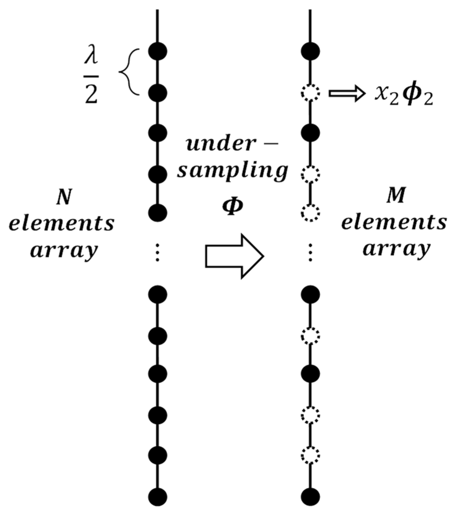
Based on the above partial Hadamard matrix construction, as shown in the above equation, the first M row and N column vectors are selected sequentially to form a new sub-matrix Φ ¯ , and finally use the CZ method to replace all elements of ϕ n where does not exist with zero, and the measurement matrix Φ is obtained, as shown in Figure 3, after under-sampling compression, the data and information received by the second array sensor that is not sampled need to use the CZ method to set all elements of ϕ 2 to zero. Therefore, we refer to this improved Hadamard matrix as the compression zeroing measurement matrix based on sequential partial Hadamard.
The improved Hadamard matrix is a deterministic measurement matrix. On the one hand, in the array signal processing, if there are several sensors error receiving or failure, we can use CZ method to zero the corresponding column vector element in the measurement matrix to remove invalid or useless data and itself interference from the array; On the other hand, in the process of compressing and under-sampling the array, as shown in Figure 3, the relationship between the array signals before and after under-sampling compression is established through the improved Hadamard matrix, the unsampled array data and redundant information are removed by the method of CZ, to accelerate the reconstruction speed and enhance the performance of target estimation.
After the above-mentioned array compression zeroing method, there is still irrelevance between the columns of the measurement matrix Φ , and when the number N is close to the number U, it can still basically satisfy the RIP.
However, the selection of U and N in the improved Hadamard matrix proposed above still has certain application conditions. The size of its construction dimension U must satisfy an integer multiple of 2, that is, s i z e ( U ) = 2 r , r = 1 , 2 , , therefore, our reconstructed N needs to be as close to U as possible. From the Hadamard matrix of U × U , and through the above introduction method, after selecting a sub-matrix of size M × N composed of M rows and N columns, which still has strong non-correlation and partial orthogonality.

4. Simulation and Experiments Analysis

4.1. Validation and Analysis Based on Simulation Signals

Before using the measured data, we compared the performance of several deterministic measurement matrices through simulation signal verification. The results show that under a high compression ratio, these deterministic measurement matrices have better reconstruction effects on known targets, but in the environment of a low compression ratio, the reconstruction effect of several measurement matrices produces the obvious difference. The relevant parameters of simulation experiments in this paper are listed in Table 1.
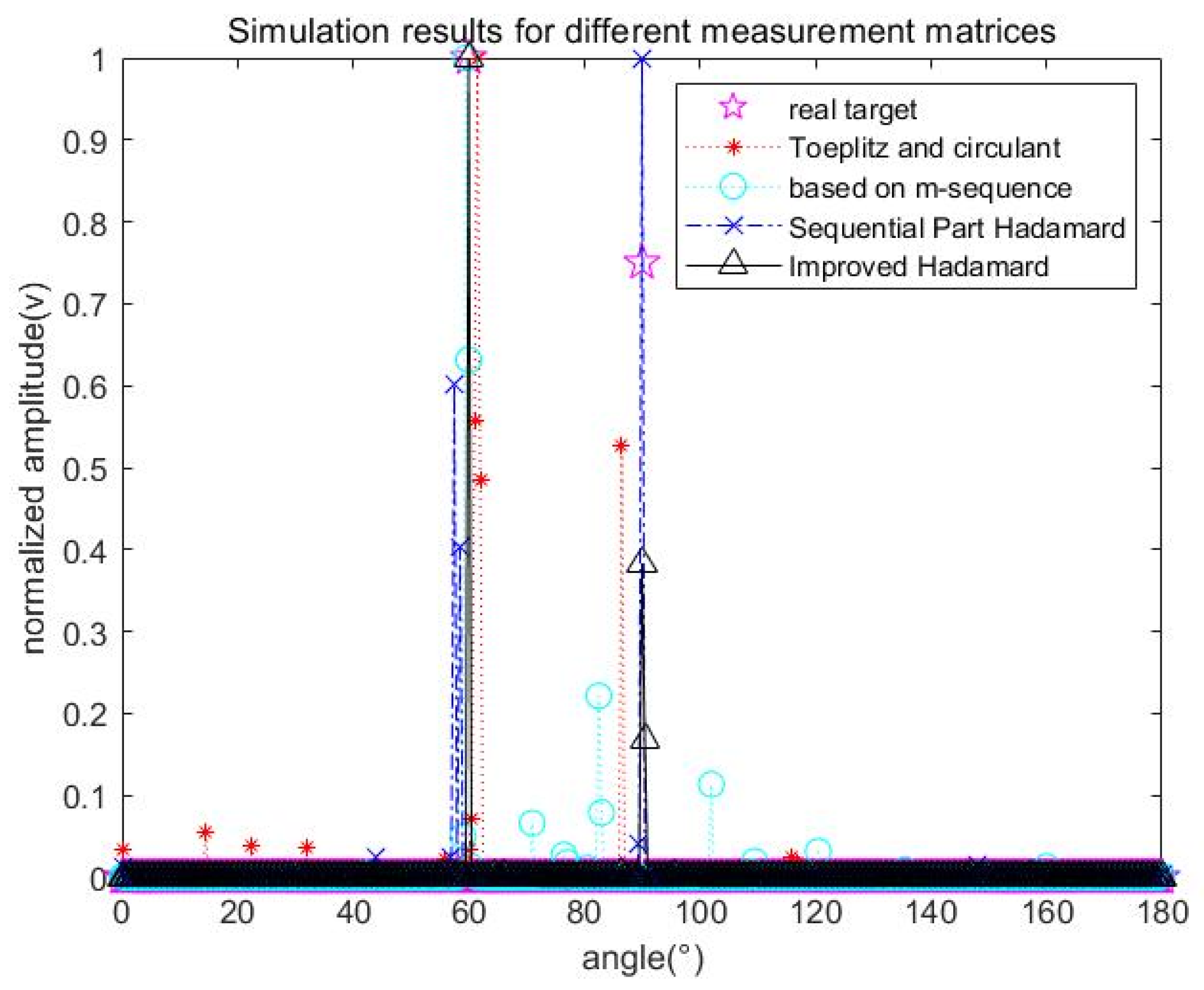
Figure 4 shows four different deterministic measurement matrices—Toeplitz and circulant. Based on m-sequence, Sequential Partial Hadamard and the Improved Hadamard measurement matrix proposed in this paper, when the compression ratio is 44%, the reconstruction effect of known target detection in simulation. It can be found that compared with other measurement matrices, the improved Hadamard matrix reconstruction effect is still significant.
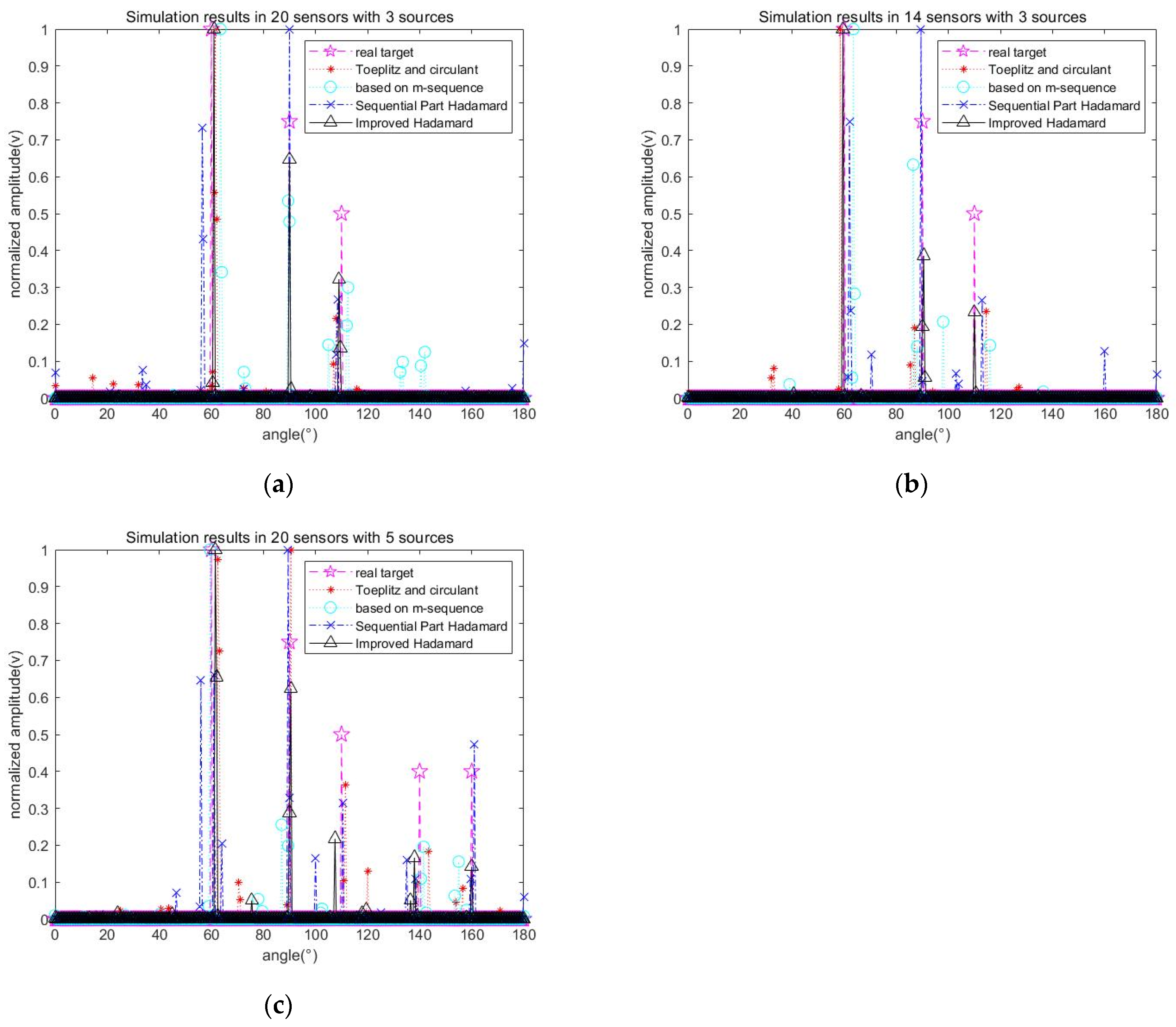
Furthermore, in order to analyze the effect in different number of sensors and sources on the performance of the improved Hadamard measurement matrix, the following simulations analysis are performed, as shown in Figure 5. To facilitate performance comparison and unified compression ratio and other variables, some simulation parameters are changed on the basis of Table 1, and the change content is shown in Table 2.
Figure 5 shows the reconstruction effect of different number of sensors and sources in known target detection simulation—2014 sensors, when the compression ratio is 50%, the target angle is [60°, 90°, 110°] or [60°, 90°, 110°, 140°, 160°], and the target amplitude is [1, 0.75, 0.5] or [1, 0.75, 0.5, 0.4, 0.4]. It can be found that compared to other measurement matrices, as the number of sensors decreases or the number of sources increases, the estimation accuracy and reconstruction amplitude will decrease, but it still has good reconstruction estimation performance, and it can reconstruct the relative correct trend for different actual amplitude sources after using the improved Hadamard matrix compression. The simulation results in 14 sensors with 5 sources were not displayed, because the resolution ability of 14 sensors for 5 sources after compression was greatly reduced, resulting in poor results.

4.2. Validation and Analysis Based on Experimental Signals

4.2.1. Test Overview

The test area is located in Moganshan Lake, and the speed of sound under the lake is about 1500 m per second, which is typical in complex lake data. As shown in Figure 6, the ULA is composed of 27 sensors, and the array element spacing is 5.48 mm, each array element of ULA sampling frequency is 1000 KHz, and the sampling time is 0.05 s. This experimental system uses linear frequency modulation (LFM) signal as the transmission signal of active sonar, and the active sonar emits an LFM signal in the range of 100–200 KHz, and the Unmanned underwater vehicle (UUV) model is the target of this experiment, the combination of active sonar and ULA is used to try to capture the trajectory of the target and to achieve the tracking and monitoring of the target.
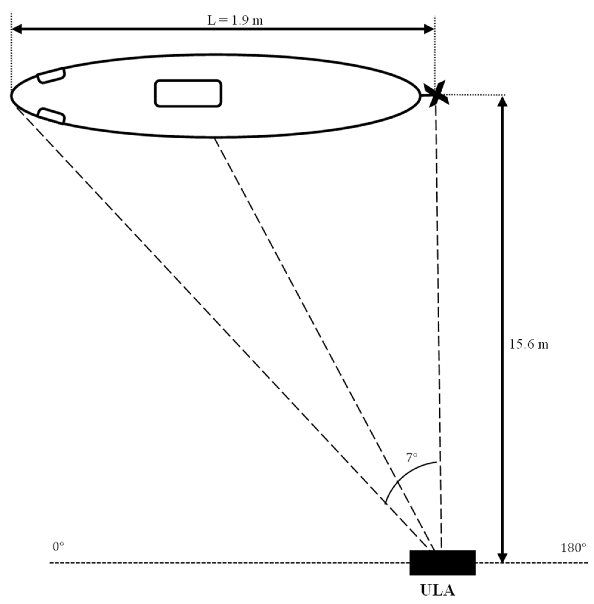
The top view of the layout of the experimental scene is shown in Figure 7, which also clearly shows the approximate layout of the UUV model and the actual array. Since the array is smaller than the UUV model in the experimental environment, we denote it with a black square in Figure 7, and we added an interference target to test the final reconstruction effect. Through the environment of the experimental arrangement, we can roughly estimate the approximate bearing of the strong target bright spots in the UUV model—the head, middle compartment, and stern part in the UUV model, such as the position pointed by the dotted line, have a stronger capture ability than other parts.
Based on the layout of the above experimental scene, we calculate the estimation of the three major reflex highlights of the UUV model. As shown in Figure 7, of course, the calculation estimate will have a certain error compared with the actual environment.

4.2.2. Results and Analysis of The Array Signal Processing

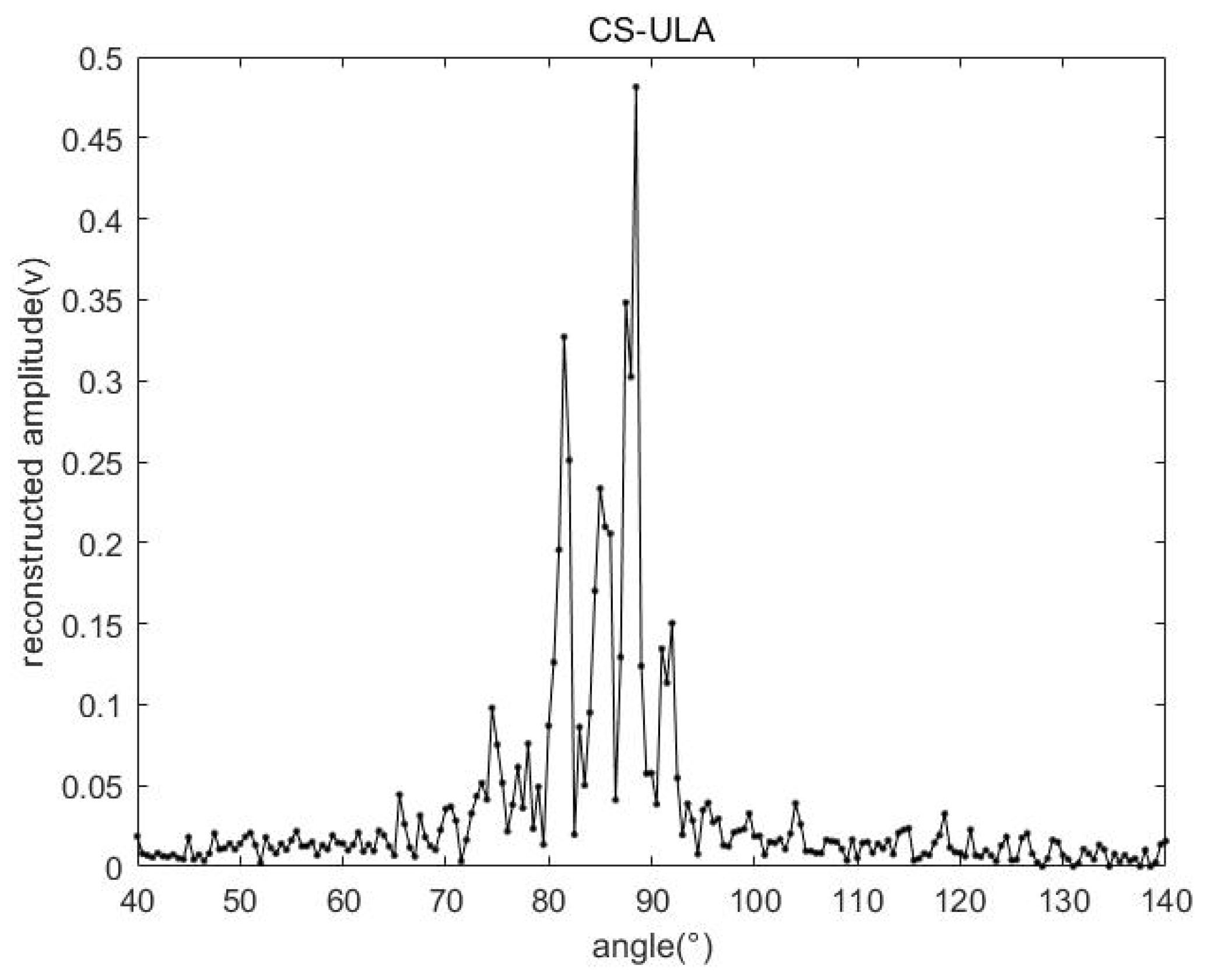
First, we compare the general wideband array signal processing method with the uncompressed spatial sparse reconstruction method proposed in this paper to process experimental data, such as the incoherent signal subspace method (ISSM) in Figure 8, and Figure 9 is the proposed method in this paper. For the uncompressed array spatial sparse reconstruction method, it can be found that the resolution of the ISSM method is not as good as the spatial sparse reconstruction method proposed in this paper, so the method proposed in this paper has obvious advantages in wideband array signal processing.
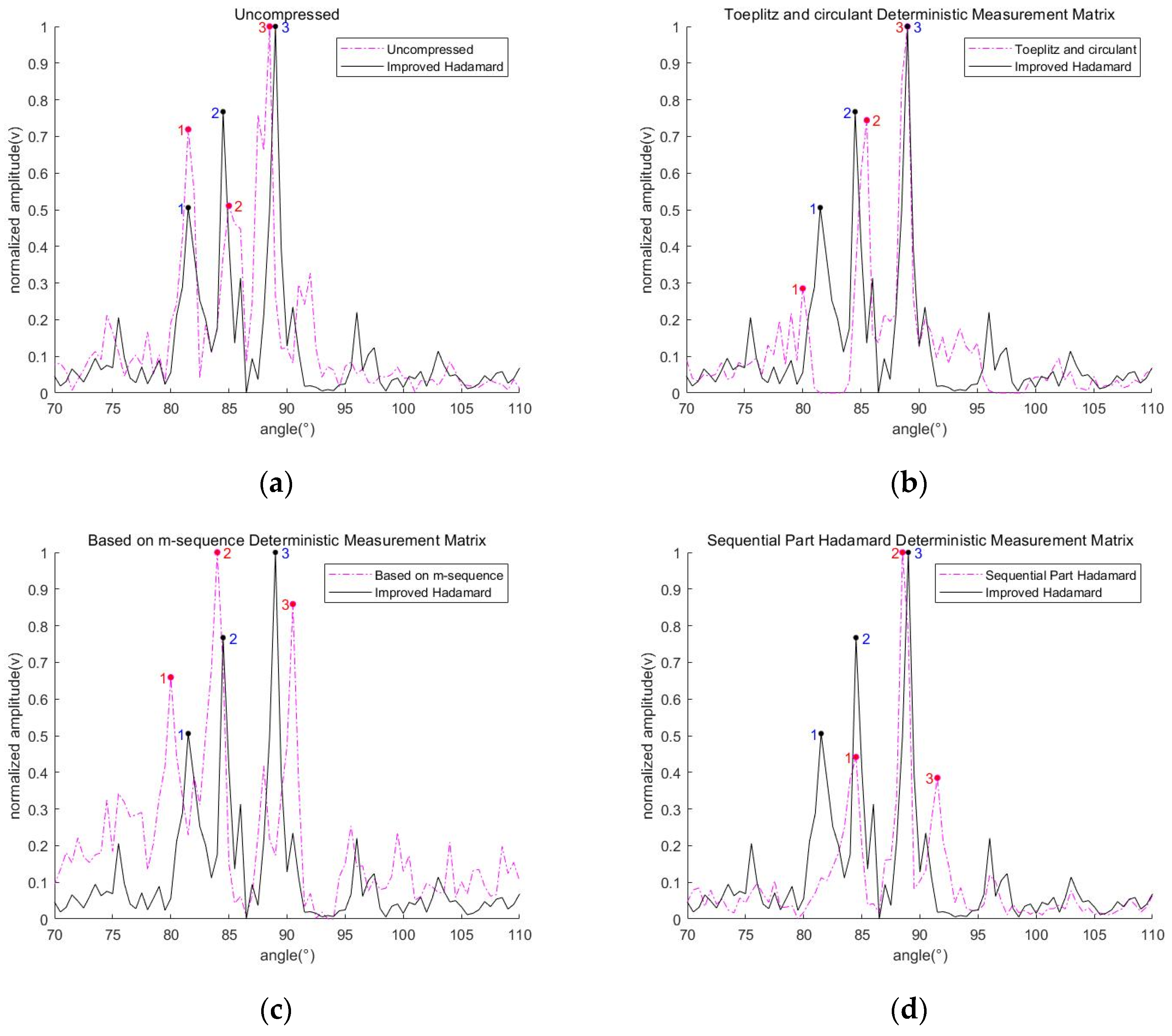
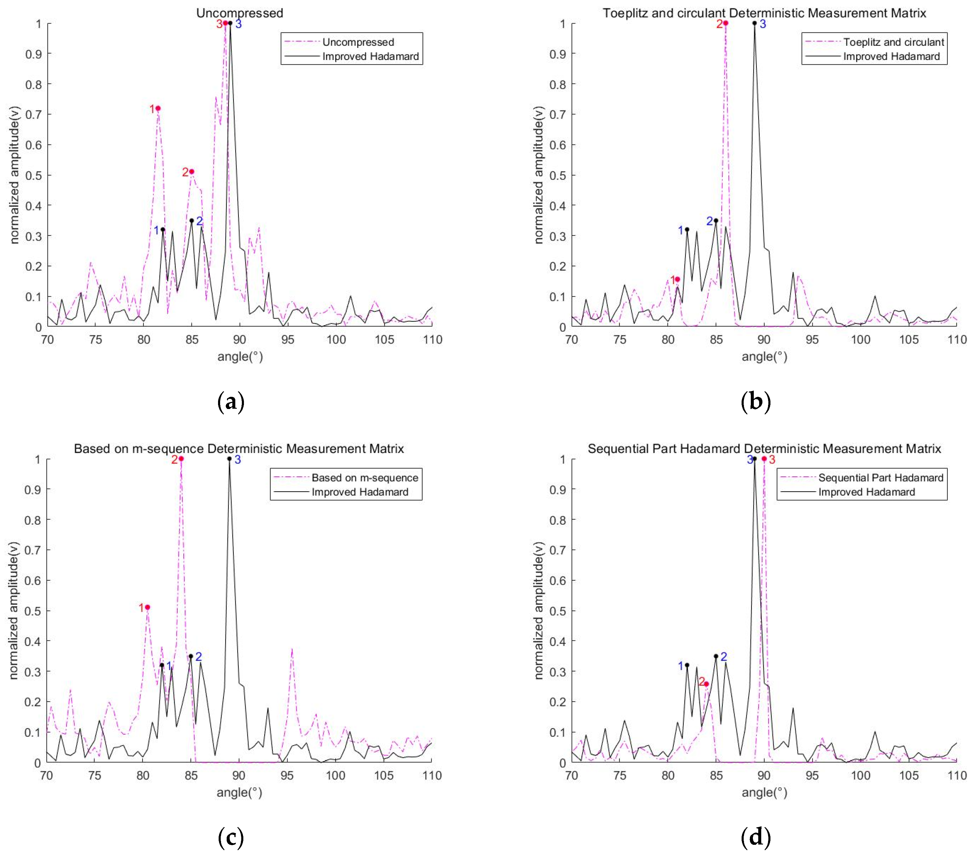
We also compare the target detection and reconstruction effects of several different measurement matrices under different compression ratios, as shown in Figure 10 and Figure 11, the reconstructed target with different measurement matrices in 70% and 44% compression ratios respectively. We normalized the final reconstruction amplitude to make the comparison between each matrix more obvious and compared the reconstruction effect before and after compression.
And the approximate position of the actual target can be known through the target azimuth estimated by each matrix at high compression ratios, or by the above reconstruction result when uncompressed, and marked as 1, 2, and 3.
It can be seen from Figure 10 and Table 3 that when in 70% compression ratio, before and after compression, the improved Hadamard matrix has a better ability to capture the three bright spots of the UUV model. It has higher resolution and smaller reconstruction error compared with the sequential partial Hadamard matrix, and it also has a certain inhibitory effect on interference.
It can be seen from Figure 11 and Table 4 that when in 44% compression ratio, except for the improved Hadamard matrix, the reconstruction performance of several other deterministic measurement matrices for the target is significantly degraded, and the reconstruction accuracy and resolution are lost. The improved Hadamard matrix can reconstruct the approximate target bright spot features although the amplitude of the reconstructed target bright spot has dropped significantly.
In addition, we also tested the limit compression ratio of the improved Hadamard matrix proposed in this paper, as shown in Figure 12 and Table 5, which are the reconstruction estimates of the improved Hadamard matrix under different compression ratios. It can be found that, as the compression ratio decreases step by step, the accuracy and resolution of the reconstruction estimation decrease, but compared with other deterministic matrices, the reconstruction effect is still considerable at low compression ratios. It was not until the compression ratio dropped to 33% that there was a relatively obvious problem of estimation error.

5. Conclusions

In this paper, we proposed a compressive sensing processing model for under-sampled array signals. Aiming at the key technology of measurement matrix, an improved Hadamard matrix based on the compression zeroing method is proposed, and the column-to-column non-correlation in the measurement matrix is enhanced, thereby improving its processing speed and reconstruction estimation performance. It can be seen from the simulation and measured data processing results that the compressive sensing processing method proposed in this paper has higher resolution, and can greatly reduce the computing time, and compared with the Toeplitz circulant matrix, m-sequence matrix, Sequential-Part Hadamard matrix, the improved Hadamard matrix proposed in this paper not only has the satisfying performance under high compression ratio, but also maintains good target orientation estimation performance at 41% compression ratio, and there is no obvious estimation error until the compression ratio is 37%. This method provides an effective way for array signal processing, especially for under-sampling array signal processing.
In addition, there are many sparse array structures that have similarities to the compression method proposed in this paper, such as the coprime array and nested array, etc., and it is also trying to use a smaller number of equivalent sensors to estimate the same number of sources or given the same number of sensors and estimate as many sources as possible. However, these sparse array structures do not have the flexibility of the method proposed in this paper. As long as a certain compression ratio is satisfied, it is not necessary to satisfy the arrangement conditions of these sparse array structures and better estimation results can be obtained.

Author Contributions

Conceptualization and methodology, T.S. and Q.G.; validation, Q.G. and M.L.; formal analysis, Y.W. and Y.G.; writing—original draft preparation, T.S. and Q.G.; writing—review and editing, Q.G.; funding acquisition, T.S. and Y.G. All authors have read and agreed to the published version of the manuscript.

Funding

This work was supported by Zhejiang Provincial Natural science foundation of China (No. LZ20F010002), and the funding from the Extension Fund from Underwater Test and Control Technology Key Laboratory (No. YS24071802).

Institutional Review Board Statement

Not applicable.

Informed Consent Statement

Not applicable.

Data Availability Statement

Data sharing not applicable.

Conflicts of Interest

The authors declare no conflict of interest.

Nomenclature

CSCompressive Sensing
DOADirection of Arrival
CBFConventional Beamforming
MVDRMinimum Variance Distortionless Response
MUSICMultiple Signal Classification
ES-DOADOA Estimation Based on Eigenspace
ESPRITEstimation Signal Parameter Via Rotational Invariance Techniques
CSACompressive Sampling Array
CSBCompressive Sensing Beamforming
CSA-ES-DOACompressive Sampling Array DOA Estimation Based on Eigenspace
ULAUniform Linear Array
CZCompression Zeroing
LFMLinear Frequency Modulation
A-OMPAdaptive Orthogonal Matching Pursuit
UUVUnmanned Underwater Vehicle
ISSMIncoherent Signal Subspace Method

References

  1. Krim, H.; Viberg, M. Two decades of array signal processing research: The parametric approach. IEEE Signal Process. Mag. 1996, 13, 67–94. [Google Scholar] [CrossRef]
  2. Sharma, A.; Mathur, S. Performance analysis of adaptive array signal processing algorithms. IETE Tech. Rev. 2016, 33, 472–491. [Google Scholar] [CrossRef]
  3. Zhai, W.Q.; Li, J.; Xie, K. Target azimuth estimation in the presence of linear array shape distortion. In Proceedings of the 2015 8th International Congress on Image and Signal Processing (CISP), Shenyang, China, 14–16 October 2015. [Google Scholar]
  4. Rehacek, J.; Paúr, M.; Stoklasa, B.; Hradil, Z.; Sánchez-Soto, L.L. Optimal measurements for resolution beyond the Rayleigh limit. Opt. Lett. 2017, 42, 231–234. [Google Scholar] [CrossRef] [PubMed]
  5. Capon, J. High-resolution frequency-wavenumber spectrum analysis. Proc. IEEE 1969, 57, 1408–1418. [Google Scholar] [CrossRef] [Green Version]
  6. Schmidt, R. Multiple emitter location and signal parameter estimation. IEEE Trans. Antennas Propag. 1986, 34, 276–280. [Google Scholar] [CrossRef] [Green Version]
  7. Zhang, X.F.; Lv, W.; Shi, Y.; Zhao, R.N.; Xu, D.Z. A novel DOA estimation algorithm based on eigen space. In Proceedings of the 2007 International Symposium on Microwave, Antenna, Propagation and EMC Technologies for Wireless Communications, Hangzhou, China, 16–17 August 2007. [Google Scholar]
  8. Donoho, D.L. Compressed sensing. IEEE Trans. Inf. Theory 2006, 52, 1289–1306. [Google Scholar] [CrossRef]
  9. Zhu, Z.; Chi, C.; Zhang, C.H. Spatial-Resampling Wideband Compressive Beamforming. In Proceedings of the OCEANS 2021: San Diego—Porto, San Diego, CA, USA, 20–23 September 2021. [Google Scholar]
  10. Hevalier, P.; Albera, L.; Férréol, A.; Comon, P. On the virtual array concept for higher order array processing. IEEE Trans. Signal Process. 2005, 53, 1254–1271. [Google Scholar] [CrossRef]
  11. Ma, W.K.; Hsieh, T.H.; Chi, C.Y. DOA Estimation of Quasi-Stationary Signals with Less Sensors Than Sources and Unknown Spatial Noise Covariance: A Khatri–Rao Subspace Approach. IEEE Trans. Signal Process. 2010, 58, 2168–2180. [Google Scholar] [CrossRef]
  12. Moffet, A. Minimum-redundancy linear arrays. IEEE Trans. Antennas Propag. 1968, 16, 172–175. [Google Scholar] [CrossRef] [Green Version]
  13. Hoctor, R.T.; Kassam, S.A. The unifying role of the coarray in aperture synthesis for coherent and incoherent imaging. Proc. IEEE 1990, 78, 735–752. [Google Scholar] [CrossRef]
  14. Pal, P.; Vaidyanathan, P.P. Nested Arrays: A Novel Approach to Array Processing with Enhanced Degrees of Freedom. IEEE Trans. Signal Process. 2010, 58, 4167–4181. [Google Scholar] [CrossRef] [Green Version]
  15. Sarangi, P.; Hücümenoğlu, M.C.; Pal, P. Single-Snapshot Nested Virtual Array Completion: Necessary and Sufficient Conditions. IEEE Signal Process. Lett. 2022, 29, 1–5. [Google Scholar] [CrossRef]
  16. Vaidyanathan, P.P.; Pal, P. Sparse Sensing with Co-Prime Samplers and Arrays. IEEE Trans. Signal Process. 2011, 59, 573–586. [Google Scholar] [CrossRef]
  17. Wang, Y.; Leus, G.; Pandharipande, A. Direction estimation using compressive sampling array processing. In Proceedings of the 2009 IEEE/SP 15th Workshop on Statistical Signal Processing(SSP), Cardiff, UK, 31 August–3 September 2009. [Google Scholar]
  18. Li, G.L.; Huang, G.M. DOA estimation based on compressive sampling array with novel beamforming. In Proceedings of the 2014 XXXIth URSI General Assembly and Scientific Symposium (URSI GASS), Beijing, China, 16–23 August 2014. [Google Scholar]
  19. Li, B.; Zou, Y.X.; Zhu, Y.S. Direction estimation under compressive sensing framework: A review and experimental results. In Proceedings of the 2011 IEEE International Conference on Information and Automation(ICIA), Shenzhen, China, 6–8 June 2011. [Google Scholar]
  20. Jouny, I. Music DOA estimation with compressive sensing and/or compressive arrays. In Proceedings of the 2011 IEEE International Symposium on Antennas and Propagation (APSURSI), Spokane, WA, USA, 3–8 July 2011. [Google Scholar]
  21. Yan, J.; Feng, N.Z.; Shen, Y. Bearing estimation of coherent signals using compressive sampling array. In Proceedings of the 2014 IEEE International Instrumentation and Measurement Technology Conference (I2MTC) Montevideo, Montevideo, Uruguay, 12–15 May 2014. [Google Scholar]
  22. Dang, K.; Ma, L.H.; Tian, Y.; Zhang, H.W.; Ru, L.; Li, X.B. Construction of the compressive sensing measurement matrix based on m sequences. J. Xidian Univ. 2015, 42, 186–192. [Google Scholar]
  23. Li, X.L.; Fan, Y.M.; Wu, L.C. Study and construction of a compressed sensing measurement matrix that is easy to implement in hardware. CAAI Trans. Intell. Syst. 2017, 12, 279–285. [Google Scholar]
  24. Ravelomanantsoa, A.; Rabah, H.; Rouane, A. Compressed Sensing: A Simple Deterministic Measurement Matrix and a Fast Recovery Algorithm. IEEE Trans. Instrum. Meas. 2015, 64, 3405–3413. [Google Scholar] [CrossRef]
  25. Li, X.B.; Zhao, R.Z.; Hu, S.H. Blocked Polynomial Deterministic Matrix for Compressed Sensing. In Proceedings of the 2010 6th International Conference on Wireless Communications Networking and Mobile Computing (WiCOM), Chengdu, China, 23–25 September 2010. [Google Scholar]
  26. Huang, T.; Fan, Y.Z.; Zhu, M. Symmetric Toeplitz-Structured Compressed Sensing Matrices. Sens. Imaging 2013, 16, 7. [Google Scholar] [CrossRef] [Green Version]
  27. Kang, C.Y.; Zhang, X.H.; Fan, W.T.; Li, J. Suppressing directional interference combining frequency domain blind source separation with beamforming. Acta Acust. 2014, 39, 565–569. [Google Scholar]
  28. Wei, J.; Yue, F.L.; Li, R.Y.; Wang, W.J.; Gao, D. A particle filter based compressive sensing method for tracking moving wideband sound sources. China Commun. 2018, 15, 197–210. [Google Scholar] [CrossRef]
  29. Kang, C.Y.; Li, Q.Y.; Jiao, Y.M.; Li, J.; Zhang, X.H. Direction of arrival estimation and signal recovery for underwater target based on compressed sensing. In Proceedings of the 2015 8th International Congress on Image and Signal Processing (CISP), Shenyang, China, 14–16 October 2015. [Google Scholar]
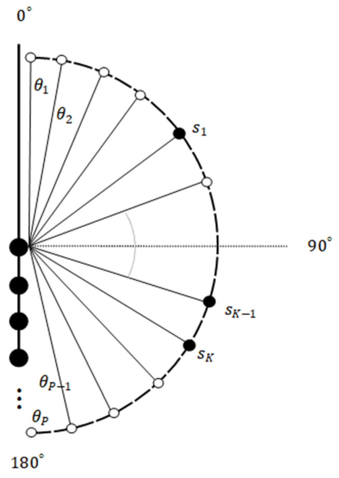
Figure 1. Received model of N-element uniform linear array.
Applsci 12 10769 g001
Figure 2. P grid points for narrowband sound sources.
Applsci 12 10769 g002
Figure 3. The process of under-sampling array.
Applsci 12 10769 g003
Figure 4. Simulation target reconstruction effect with a compression ratio of 44%.
Applsci 12 10769 g004
Figure 5. Simulation target reconstruction effect in different number of sensors and sources: (a) simulation results in 20 sensors with 3 sources; (b) simulation results in 14 sensors with 3 sources; and (c) simulation results in 20 sensors with 5 sources.
Applsci 12 10769 g005
Figure 6. View of the underwater experiment scene layout.
Applsci 12 10769 g006
Figure 7. Top view of the layout of the experimental scene.
Applsci 12 10769 g007
Figure 8. Detection effect based on incoherent signal subspace method.
Applsci 12 10769 g008
Figure 9. Reconstruction effect based on spatial sparse reconstruction method.
Applsci 12 10769 g009
Figure 10. The reconstructed targets with different measurement matrices in 70% compression ratio: (a) the reconstructed targets under uncompressed observations; (b) the reconstructed targets with Toeplitz and circulant Deterministic Measurement Matrix; (c) the reconstructed targets with based on m-sequence Deterministic Measurement Matrix; and (d) the reconstructed targets with sequential Part Hadamard Deterministic Measurement Matrix.
Applsci 12 10769 g010
Figure 11. The reconstructed targets with different measurement matrices in 44% compression ratio: (a) the reconstructed targets under uncompressed observations; (b) the reconstructed targets with Toeplitz and circulant Deterministic Measurement Matrix; (c) the reconstructed targets with based on m-sequence Deterministic Measurement Matrix; and (d) the reconstructed targets with sequential Part Hadamard Deterministic Measurement Matrix.
Applsci 12 10769 g011
Figure 12. The reconstructed targets with improved Hadamard matrix in different compression ratio: (a) the reconstructed targets with improved Hadamard matrix in 70% and 60% compression ratio; (b) the reconstructed targets with improved Hadamard matrix in 52% and 44% compression ratio; (c) the reconstructed targets with improved Hadamard matrix in 41% and 37% compression ratio; and (d) The reconstructed targets with improved Hadamard matrix in 33% compression ratio.
Applsci 12 10769 g012
Table 1. Simulation parameters.
ParameterValue
Array typeLinear array
Sensors number27
Underwater speed1500 m/s
Central frequency150 kHz
Sampling frequency1000 kHz
Element spacing0.005 m
Target angle[60°, 90°]
Target amplitude[1, 0.75]
gridding[0:0.5:180]
Number of sensors after compression11
Table 2. Simulation parameter changes.
ParameterValue
Sensors number2014
Target angle[60°, 90°, 110°, 140°, 160°]
Target amplitude[1, 0.75, 0.5, 0.4, 0.4]
compression ratio50%
Number of sensors after compression10, 7
Table 3. The angle of a mark in 70% Compression Ratio.
In 70% Compression Ratio
Mark123
Uncompressed81.5°85°88.5°
Improved Hadamard81.5°84.5°89°
Toeplitz and circulant80°85.5°89°
Based on m-sequence80°84°90.5°
Sequential-Part Hadamard84.5°88.5°91.5°
Table 4. The angle of a mark in 44% Compression Ratio.
In 44% Compression Ratio
Mark123
Uncompressed81.5°85°88.5°
Improved Hadamard82°85°89°
Toeplitz and circulant81°86°-
Based on m-sequence80.5°84°-
Sequential-Part Hadamard-84°90°
Note: the ‘-’ in the table represents that the target bright spot is not detected.
Table 5. The angle of a mark in different Compression Ratio.
Improved Hadamard
Compression Ratio123
70%81.5°85°89°
60%81.5°84.5°89°
52%82°84.5°88.5°
44%82°85°89°
41%81.5°85°89°
37%82.5°84.5°89.5°
Publisher’s Note: MDPI stays neutral with regard to jurisdictional claims in published maps and institutional affiliations.