Article

Test Stand for a Motor Vehicle Powered by Different Fuels

1
Faculty of Mechanical Engineering, Lublin University of Technology, 22-618 Lublin, Poland
2
M. S. Group Sp. z o.o., 00-193 Warszawa, Poland
3
UTH, 26-600 Radom, Poland
4
PANS, 22-100 Chełm, Poland
*
Author to whom correspondence should be addressed.
Appl. Sci. 2022, 12(20), 10683; https://doi.org/10.3390/app122010683
Submission received: 8 September 2022 / Revised: 7 October 2022 / Accepted: 18 October 2022 / Published: 21 October 2022
(This article belongs to the Section Mechanical Engineering)

Abstract

:
This article discusses current testing methods for motor vehicle engines. Traction engines have so far been tested, for example, according to WLTP (Worldwide Harmonized Light Vehicle Test Procedure) driving tests, but due to the “VW—gate” incident, these are now to be supplemented by RDE (Real Driving Emissions) tests, conducted under real road conditions. The analyses of the state of knowledge and the directions of research to date unequivocally indicate the need for the construction of a stand that allows: testing of a complete vehicle admitted to traffic; testing of a motor vehicle with the possibility of simulating real operating conditions; load setting with the possibility of its regulation; feeding the engine with various fuels; modification of the software of controllers having a direct impact on the control strategies of the engine; transmission and traction control system; reading, recording and analysis of the parameters of the operation of control systems in real time; detailed recording and analysis of the combustion process occurring directly in the combustion chamber; and the measurement of emitted toxic substances. On a bench with the above features, tests were carried out on a diesel motor vehicle, which were based on recording changes in the parameters of the combustion and injection process. The tests were conducted under static and dynamic conditions. Tests under static conditions were conducted on a chassis dynamometer. They consisted of indicating the engine for different fuel dose control maps. The vehicle equipped with the test engine was driven at a constant speed on the chassis dynamometer and loaded with a drag force of 130 Nm. Tests under dynamic conditions were conducted under real traffic conditions. They were limited to the presentation of results under static conditions. The main results of the tests are given in the conclusion and include a general summary. In particular, the presented results of the diesel tests demonstrate an attempt to adapt the engine to co-power with hydrogen.

1. Introduction

Due to increasing public pressure to reduce harmful substances emitted by internal combustion engines, real-world traffic tests have started to be conducted. During the conducted research, vehicle engines were fueled with alternative fuels (non-renewable as well as renewable fuels, e.g., based on vegetable oils). This study, due to significant limitations (the need for mobile specialized testing equipment, the lack of control of the injection process), as a rule, was limited to the measurement and analysis of toxicity and opacity of exhaust gases.
A significant part of the research was carried out on chassis dynamometers, where, in addition to analyzing exhaust gas toxicity and fuel consumption, the power and torque waveforms of the test vehicles’ engines were determined. Previous research has not taken into account the impact of other systems installed in vehicles (ABS—Anti-lock Braking System, ESP—Electronic Stability Program, automatic transmission) that have a direct or indirect effect on the control of the combustion process in real conditions. Studies of the operation of engines fueled by conventional and alternative fuels have been conducted over the years at many research centers around the world [1,2,3,4,5,6,7,8]. The oldest tests used simple diesel engines with a prechamber and an in-line fuel pump [9,10]. With the passage of years and the obvious development of automotive technology, diesel engines with direct fuel injection and rotary fuel pumps were used as test subjects [11,12]. Towards the end of the last century, diesel engines with direct injection and common rail (CR) or pump fuel system began to be used [13,14,15,16,17]. Mostly in the work carried out, stationary engine dynamometers were used, where different types of brakes were applied, viz: water brake, electro-vortex brake or friction brake. The use of stationary engine dynamometers for research had many advantages, including, first of all, the repeatability of the conducted experiment, as well as, importantly, the possibility of controlling injection parameters (in diesel engines) and injection and ignition parameters (in spark-ignition engines). The aforementioned engines (test subjects) were mounted on a dynamometer stand and connected to specialized test equipment. In this type of research, the engine parameters were mainly determined under conditions of external operating characteristics, less often under conditions of load characteristics, and the thermodynamic parameters of the combustion process were analyzed on the basis of an indicator chart, where the measurement was usually performed using a piezo-quartz pressure sensor mounted in the combustion chamber [18]. Stationary braking stands also allowed tests to be performed that would experimentally explain the specifics of the operation of an internal combustion engine in dynamic (transient) conditions and the reasons for the observed differences in the course of working processes compared to comparable static conditions [19,20,21].
Due to the stationary nature of the test stands, it was quite easy to determine the ecological parameters of the exhaust gases (CO, CO2, HC, NOx, smoke) and it was possible to measure (in a volumetric or mass way) fuel consumption (unit and hourly fuel consumption were determined) [22,23]. However, despite the significant advantages of using such test stands, they did not reflect the actual operating conditions of an internal combustion engine under which a vehicle powered by conventional or alternative fuels is operated.
Current research trends are include the use of alternative power sources for internal combustion engines and the use of hybrid or electric drives [24,25,26,27,28,29,30]. Many motor vehicle companies are struggling to meet regulatory requirements related to the emission of toxic components from vehicles equipped with internal combustion engines. The controversy involving vehicles manufactured by VW is well known. As a result, it has led to a reduction in the sale of diesel cars in Europe. Despite the above facts, there is currently no alternative to diesel engines used on a large scale in the heavy transport sectors (trucks, locomotives, agricultural tractors). An analysis of trends and conditions for the development of the fuel structure of automobiles led to the conclusion that in the 2035 perspective, further growth in the number of cars in operation will be based primarily on diesel-powered cars [31].
Modern vehicles have begun to use exhaust after-treatment systems, EGR—Exhaust Gas Recirculation, DPF—Diesel Particulate Filter, SCR—Selective Catalytic Reduction, which have a significant impact on the course of the combustion process as well as on the toxicity of exhaust gases. In addition, modern fuel injection systems (Common Rail) are used, which operate on the basis of appropriate precisely-selected control strategies stored in the ECU (Engine Control Unit). The use of alternative fuels in diesel engines, based on vegetable oils (rapeseed oil, soybean oil and others), due to significant differences in physicochemical properties (in particular, viscosity) relative to ON, is difficult [32,33,34,35,36,37,38,39,40,41,42,43]. Therefore, to counteract these problems, attempts have been made to modify the engine itself (Ellsbett technology) as well as its accessories (fuel heating systems, dual-fuel systems) [44]. The above solutions were applied by testing the engine in static conditions such as the engine dynamometer and chassis or in real conditions. Previous studies have not attempted to modify the control maps of the ECU—Engine Control Unit (maps affecting the control of injection parameters and maps controlling the turbocharger, EGR—Exhaust Gas Recirculation) of a serial (homologated) vehicle, taking into account its actual traffic conditions.
The analysis of the state-of-the-art technology and the direction of research to date clearly indicate the need to build a test bed for vehicle testing, which should allow:
Motor vehicle testing with simulated real-world traffic (WLTP—Worldwide Harmonized Light Vehicle Test Procedure, RDE—Real Driving Emissions);
  • Load setting with the possibility of its smooth adjustment;
  • Powering the engine with different fuels;
  • Modifying software that directly affects the control strategies of the injection process, transmission and traction control systems;
  • Real-time reading, recording and analysis of control system operating parameters;
  • Detailed recording and analysis of the combustion process occurring directly in the combustion chamber;
  • Measurement of emitted toxic substances.
  • The position should integrate all the functionality listed above.

2. Materials and Methods

This paper presents a test stand for testing a diesel vehicle fueled by different fuels, (Figure 1). The test stand was divided into three sections:
I—a test vehicle and a chassis dynamometer that reflects the actual movement of the vehicle;
II—a system for recording parameters of the fast-changing injection and combustion process and for recording parameters monitoring data acquired from the UCU controller through the OBD connector;
III—apparatus for reading/writing and programming ECUs and TCUs.
The first section presents the test object, which was an engine with a ZS built in the vehicle, a Fiat Qubo, which met the EURO 5 standard. The data and technical parameters of the test engine are given in Table 1. The test vehicle was coupled to a DF4FS-HLS chassis dynamometer with DynoRace control software.
The chassis dynamometer reflecting the actual movement of the vehicle in addition to the ability to determine the course of torque and power is equipped with the ability to read additional parameters of engine operation such as:
  • Intake air temperature;
  • MAP (Mass Air Pressure) intake manifold pressure;
  • AFR (Air to Fuel Ratio);
  • Engine oil temperature;
  • Speed of rotation;
  • Exhaust gas temperature.
Testing of an approved motor vehicle with simulated traffic under actual operating conditions is made possible by available tests:
  • Measurement of acceleration versus speed;
  • Measurement of acceleration versus vehicle speed;
  • Measurement at constant engine speed versus time;
  • Programmable driving cycles;
  • Manual speed control using a manually controlled load;
  • Taking into account the force of rolling resistance and elevation.
The technical parameters of the chassis dynamometer [45] are included in Table 2.
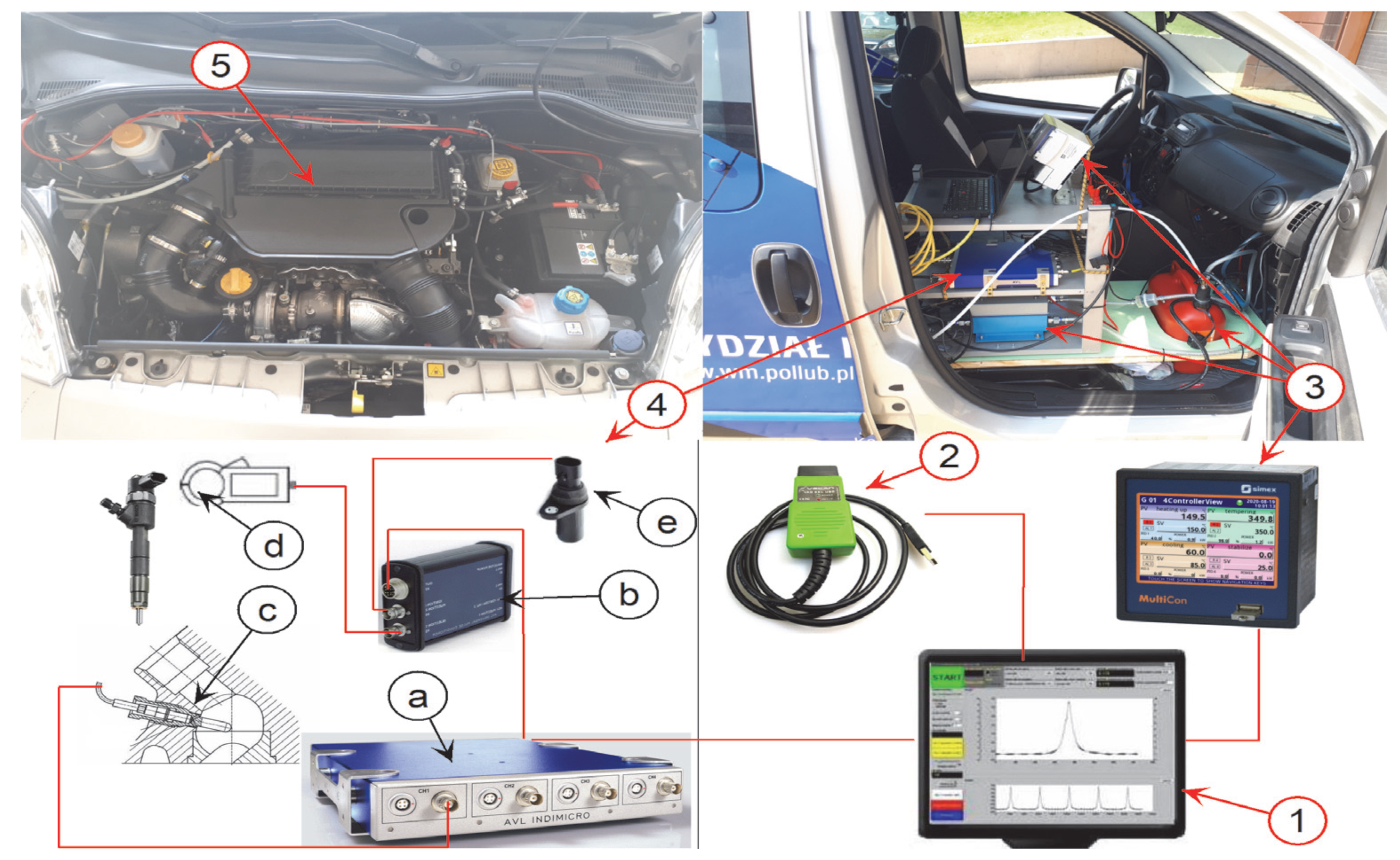
In the second section of the test stand for a vehicle fueled by different fuels, the control, measuring and recording apparatus is presented, the various components of which are shown in Figure 2. In addition, an independent fuel system is used, which allows the rapid replacement of the tested fuels and the measurement of fuel consumption.
AVL’s INDIMICRO 602 engine indicating system with an integrated signal amplifier has been built into the vehicle, working with four analog input channels and two digital inputs, allowing real-time recording of high-speed variable parameters [46,47]. Signals recorded by the AVL Indimicro system are: the course of pressure inside the cylinder, which was recorded with a piezoelectric sensor AVL GH13P mounted in the glow plug socket of the first cylinder with the help of an adapter, the signal of which was processed in the amplifier: measurement module AVL; and the engine crankshaft position signal, which informs about the position of the crankshaft, obtained from an inductive sensor cooperating with the gear flywheel via an analog-to-digital converter: AVL Universal Pulse Conditioner 389Z01; the injection parameters were analyzed on the basis of the analog control signal of the electromagnetic injector after processing into a digital signal.
A diagnostic interface designed to work with the FIAT MULTIECUSCAN program was used for registration. The system used makes it possible to:
  • Record and export diagnostic data to CSV file;
  • Read ECU identification data;
  • Read error codes;
  • Erase error codes;
  • Read parameters during engine Live Data;
  • View parameter graphs;
  • Carry out actuator tests;
  • Provide a detailed description of fault codes, parameters and actuators;
  • Reset and function programming.
The self-contained fuel system (Figure 2 item 3), which allows a quick exchange of test fuels and the measurement of fuel consumption, consists of an additional fuel tank, an additional fuel pump, additional fuel filter, a fuel unit ZPR 1B/S by Rotametr, i.e., flow meter PMZP-1A, designed for the accurate measurement of fuel consumption and a counter module: data logger MultiCon CMC-99, used for to visualize and record measurement results.
The station was also expanded to include an installation for the precise metering of fuels in the gaseous state. Thanks to the appropriate location of the dosing points of the gas used, the possibility of burning liquid fuels (diesel, rapeseed oil) in the presence of gaseous fuels (LPG, CNG, hydrogen) was obtained. The dosing installation installed gives the possibility to control the proportion between the fuels used.
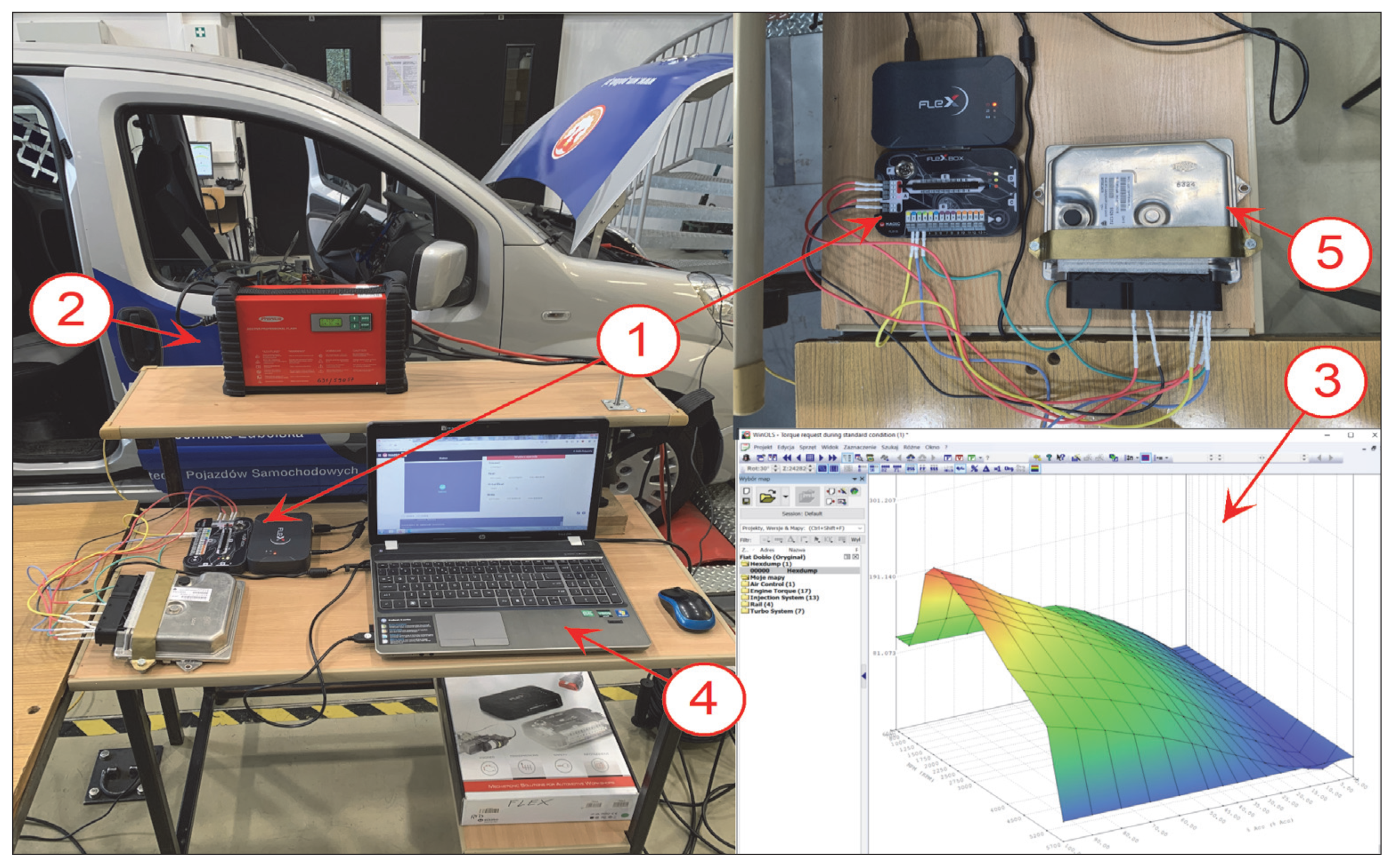
The third section of the test bed for a vehicle running on different fuels shows the apparatus used to read/write and program the ECU and TCU [48]. Figure 3 shows the various components of the system.
The FLEX device from Magicmotosport allows reading the contents of the memory of controllers through the OBD connector in vehicles using diagnostic protocols: ISO 15765:2 × CAN, ISO 99141-2 and ISO 14230: 2 × K-LINE, 1 × L-LINE, Ethernet, SAE J1850 PWM, VPW and SAE J1708.
In addition, reading in Bench and Boot mode is possible. The main function of the device is reading and writing FLASH and EEPROM memory, as well as full cloning of ECUs and TCUs. The Flex device in Master mode allows you to open the read memory areas and thus modify them independently.
To modify the controller’s read memory contents, we used WinOLS software, which has the functions:
  • Representation of raw data is in the form of 2D graphics or a hexadecimal/decimal snapshot. Automatic processor detection to distinguish between program and calibration data area;
  • Automatically search for map areas and place them in the map list;
  • Display maps in 3D/2D or as a table;
  • Automatic search for ECU and software numbers;
  • Choice of language;
  • Ability to calculate checksums;
  • Import and export of binary files;

3. Results

In order to test the test stand, a test course was established based on recording changes in the parameters of the combustion process and engine operation. Changes were made to the start correction of the first pilot injection ((+)4 deg PREinj), the main injection angle ((+)2 deg MAINinj), and the amount of injected fuel of the first pilot injection ((+)1 mm3 PREinj). Reference was made to the results of measurements of engine operating parameters at serial settings, and a reading of the contents of the engine controller’s memory was performed, after which maps affecting the operating parameters that were planned to be changed were found in the controller.

Modifying the Control Map

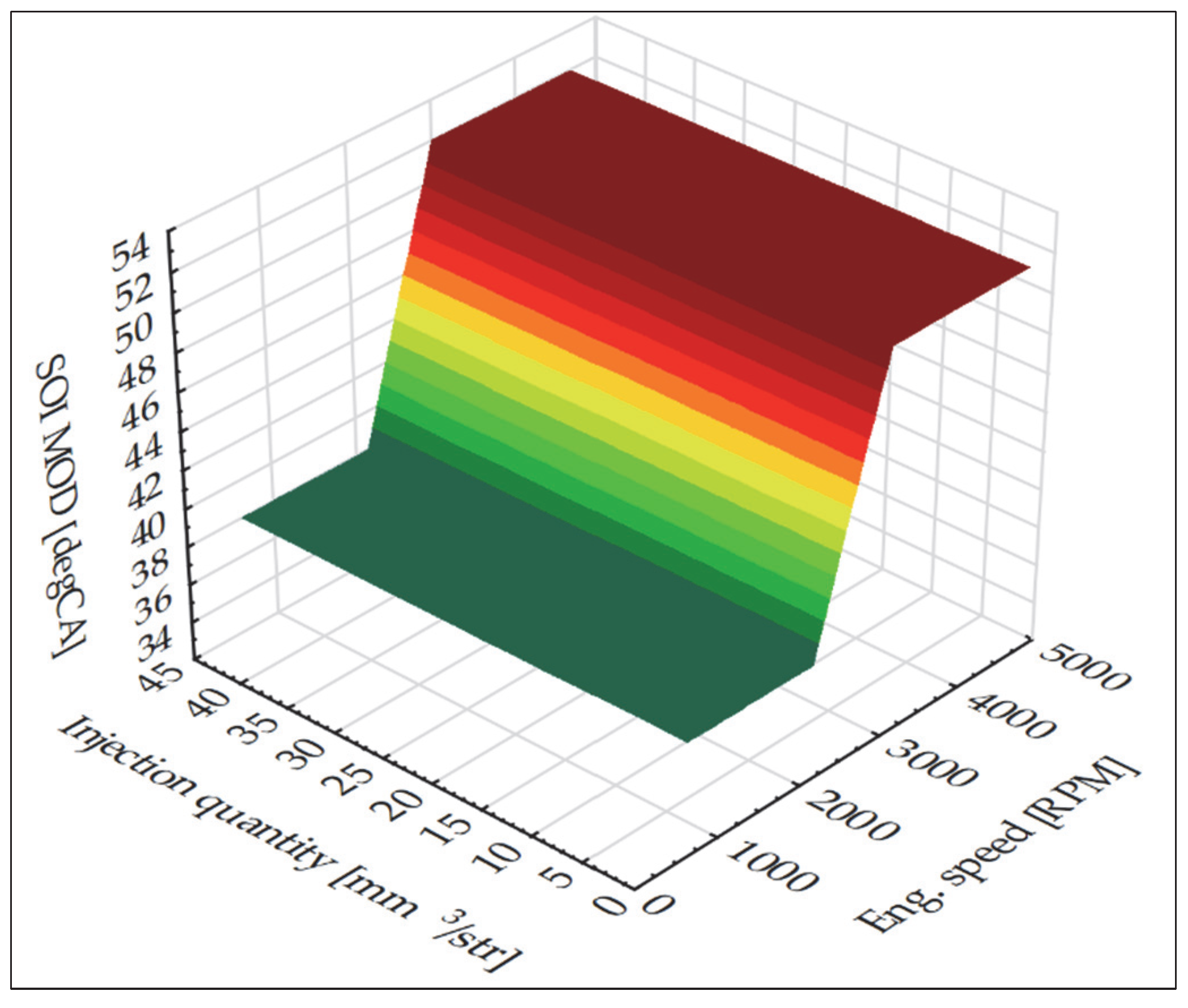
Changing the start angle of the first pre-injection by 4°. In the WinOls environment, we proceeded to modify the serial SOI [degCA] (Start of injection) control map shown in Figure 4 as a function of rotational speed [RPM] (Eng. Speed) and fuel injection quantity [mm3/str] (Injection quantity). Figure 5 shows the SOI map after modification.
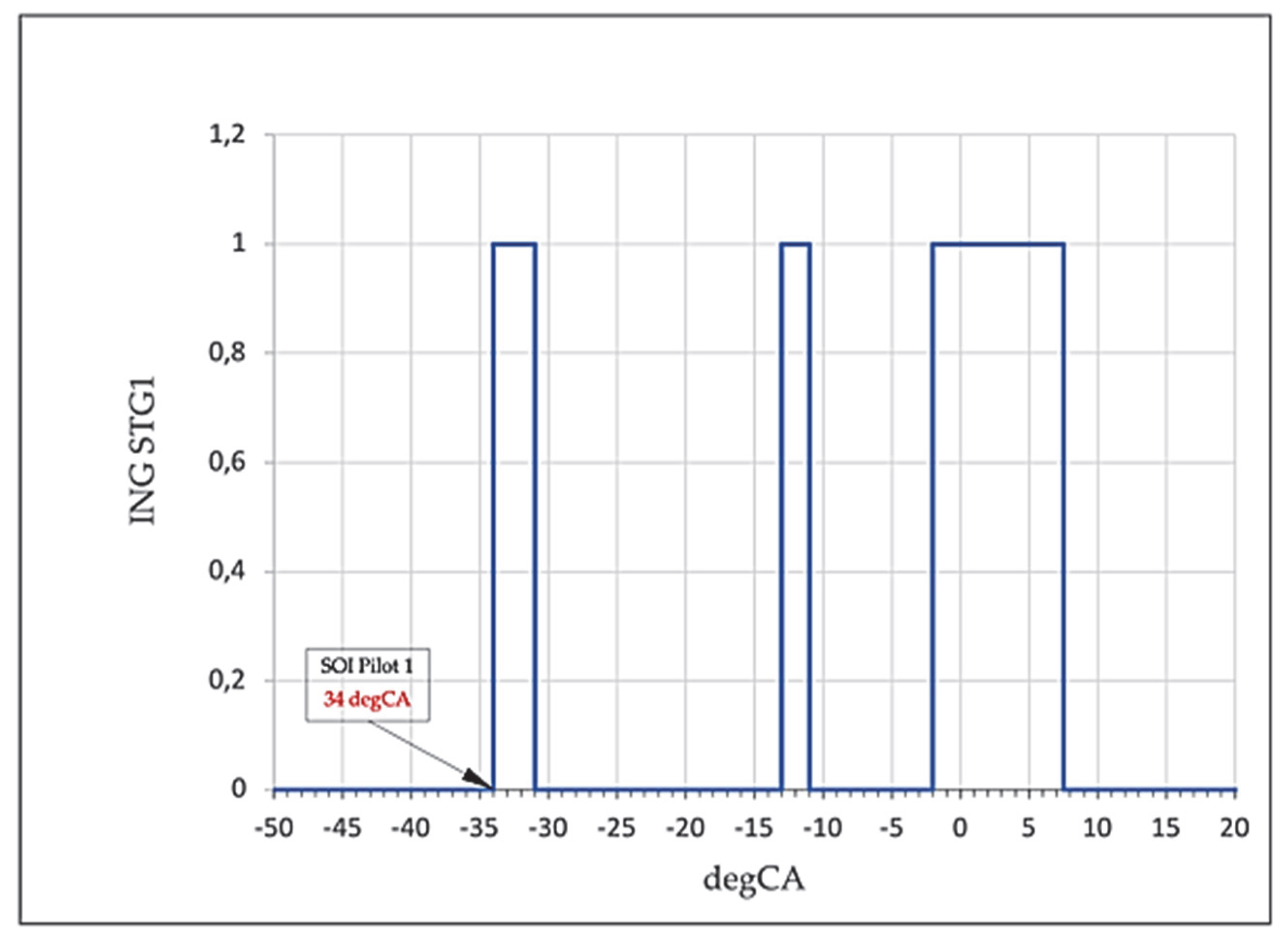
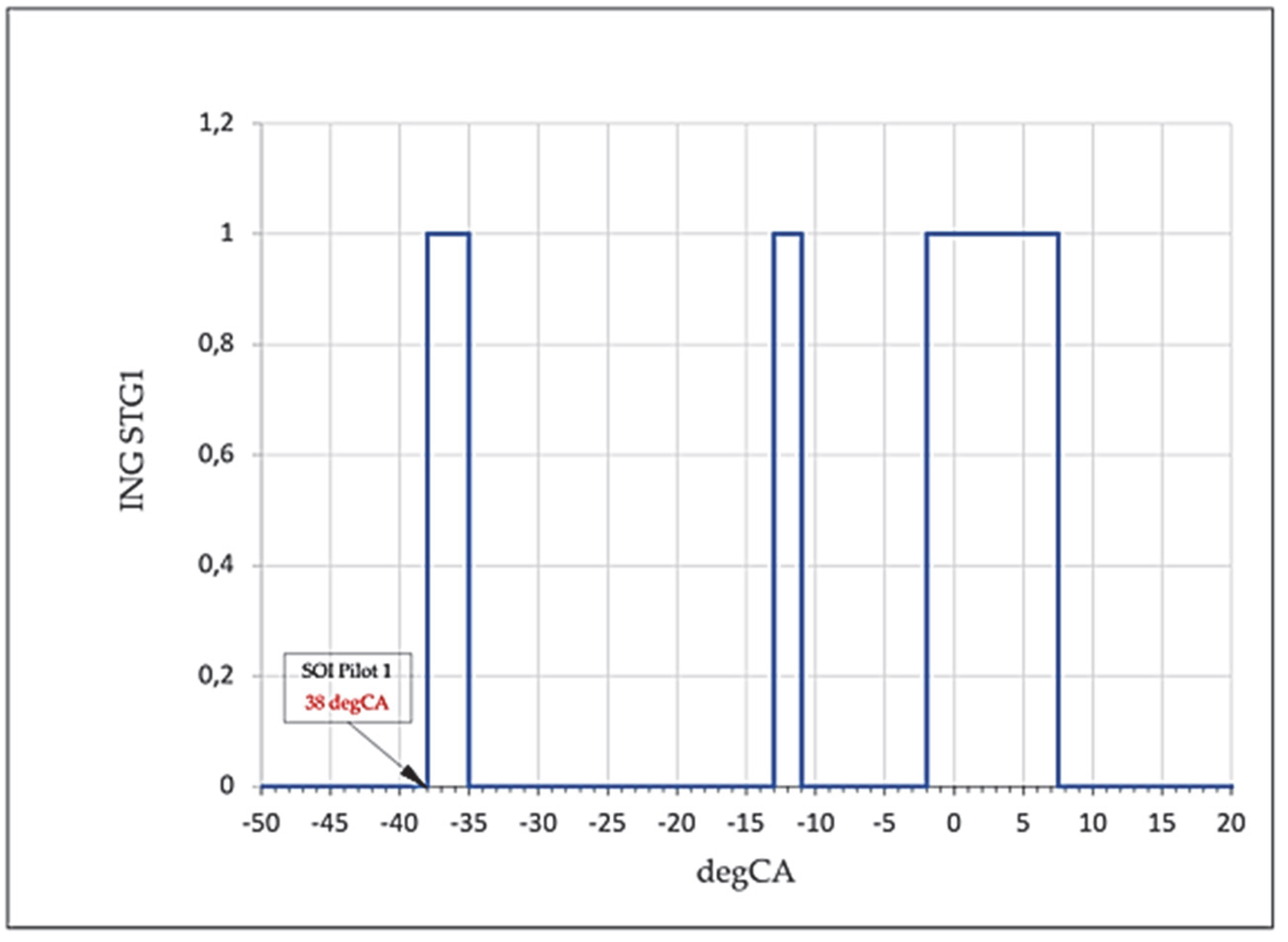
After implementing the modified memory code into the ECU (Engine Control Unit), tests were carried out to check the effect of the modification on combustion parameters, using IndiCom software. Measurements were made of the injector’s steering as a function of the crankshaft rotation angle at the factory settings, as shown in Figure 6. Modification of a selected section of the relevant control map had a direct effect on shifting the first pre-injection by the planned value, as shown in Figure 7.
Similarly, modifications were made to the main injection angle and the amount of injected fuel of the first pilot injection. The modifications carried out were performed with diesel fuel. The coolant temperature was a minimum of 90 °C. Road driving simulations on a chassis dynamometer were carried out with 3rd gear engaged, at a constant speed of 2000 RPM, and with braking force increased in steps up to 130 Nm. After the established test conditions were achieved with a constant vehicle braking force of 130Nm, measurement and recording of engine operating parameters, measurement of indexed pressure and monitoring of injection phases continued.

4. Discussion

The test results of the two modifications made to the vehicle’s ECU software are presented below. Table 3 assigns the numbers of the modifications carried out.
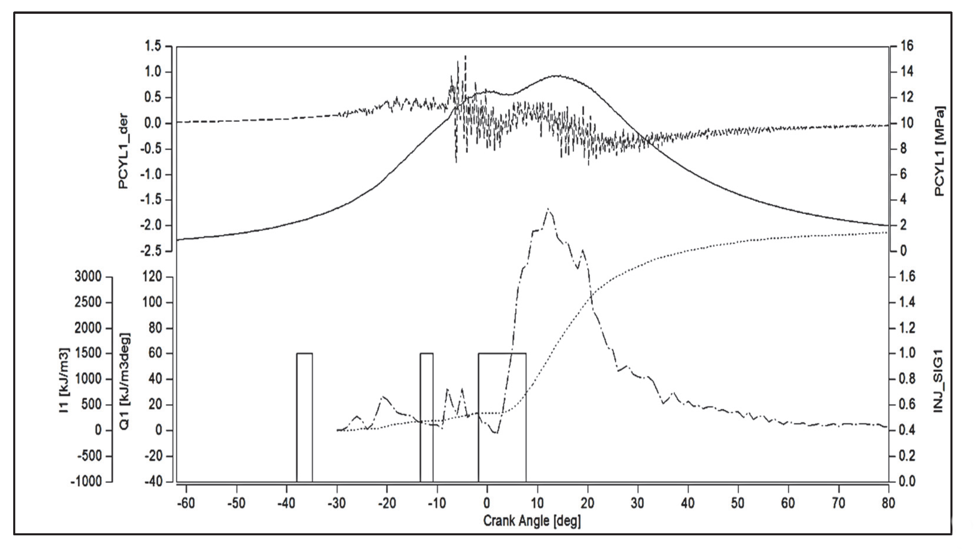
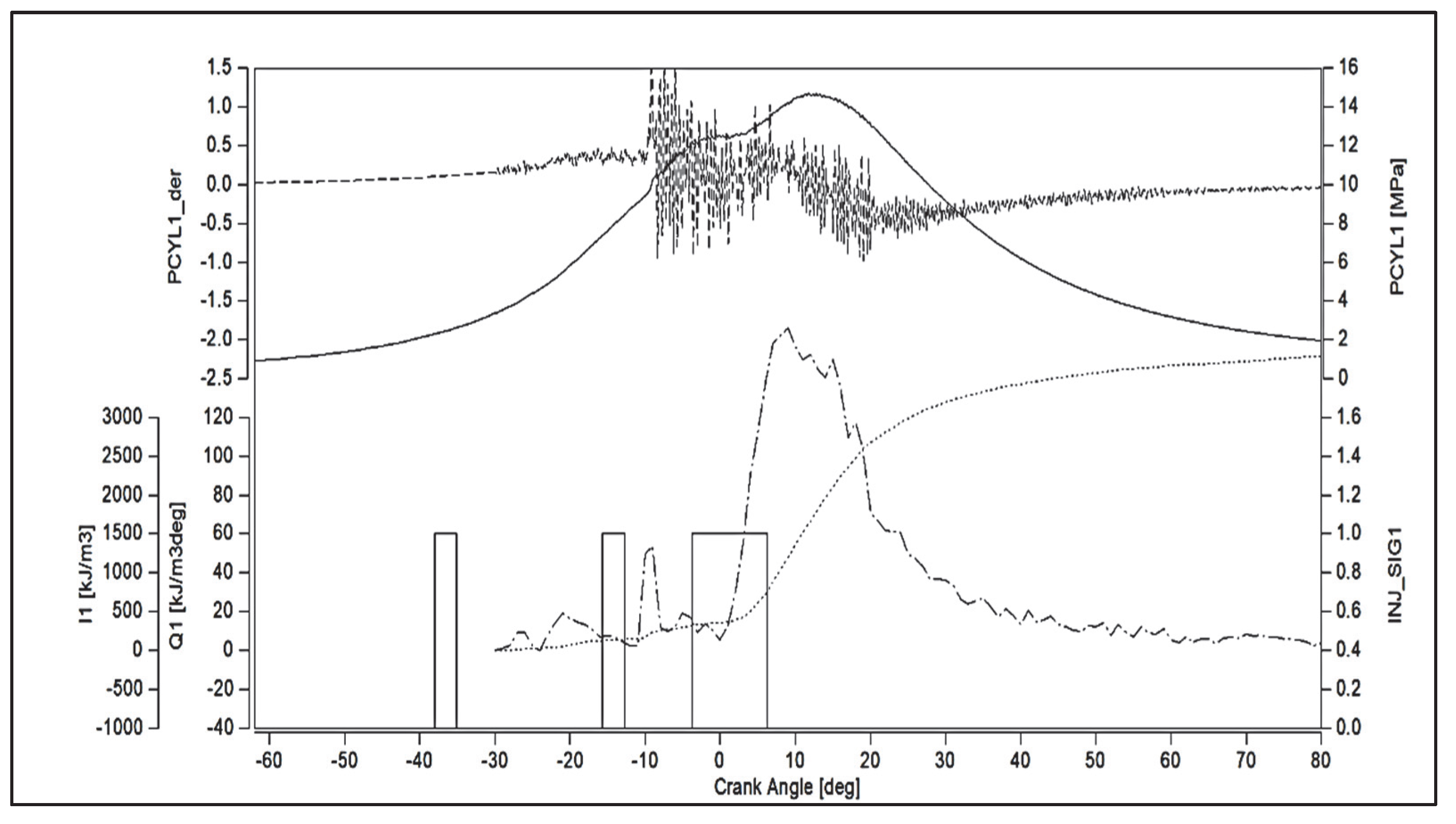
As a result of the engine indirection, the main parameters of the combustion process were determined, such as the combustion pressure PCYL1 [MPa], the maximum rate of build-up of combustion pressure PCYL1_der [MPa/deg], the average indirection pressure IMEP [MPa], as well as the waveforms of the rate of derivation of combustion heat Q1 [kJ/m3 deg] and the amount of derivation of combustion heat L1 [kJ/m3]. Figure 8 shows the recorded engine indexing waveforms and the injector control signal of the serial engine control map. Figure 9 and Figure 10 show the waveforms after modifications. Table 4 shows the results of the measurements.
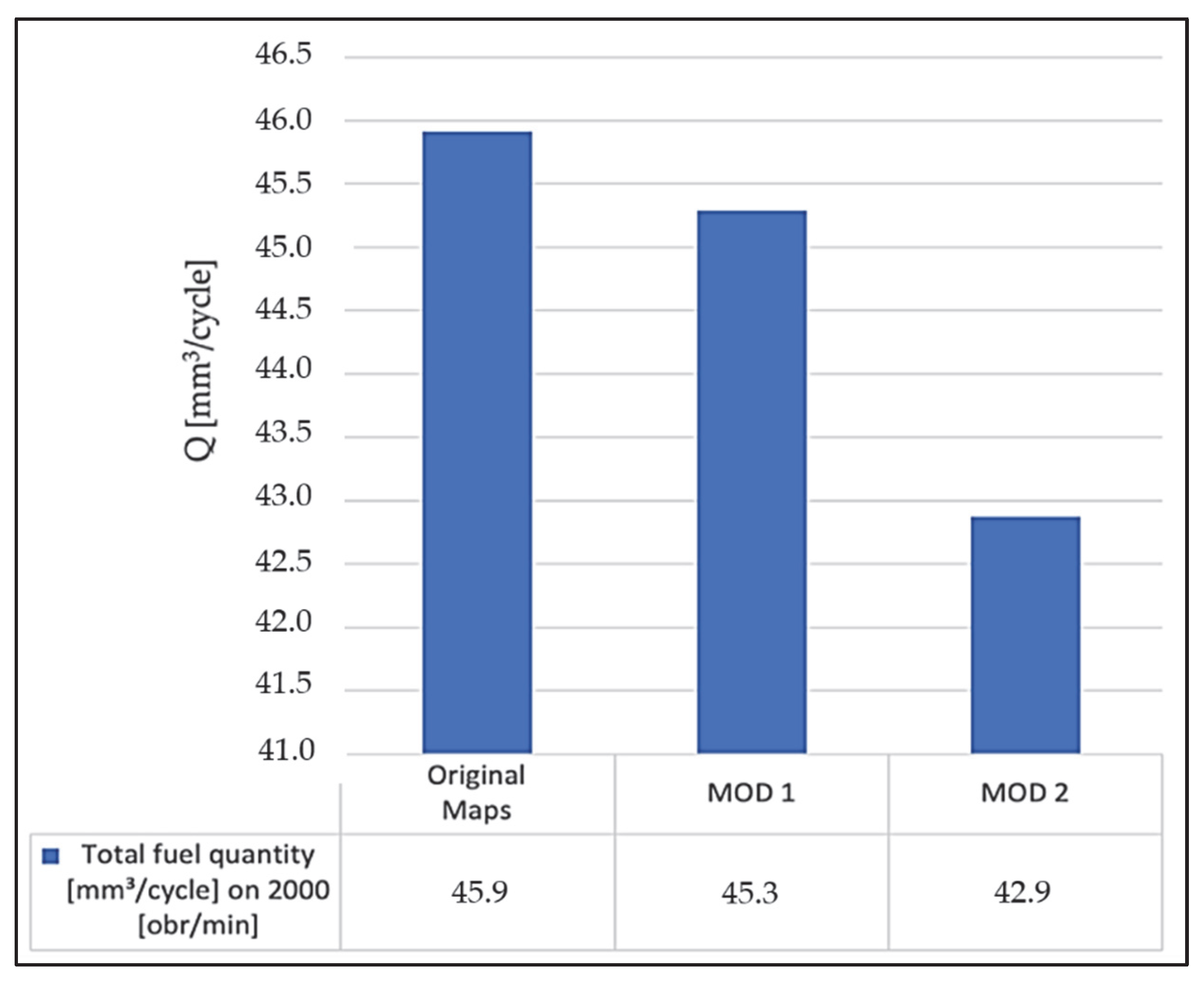
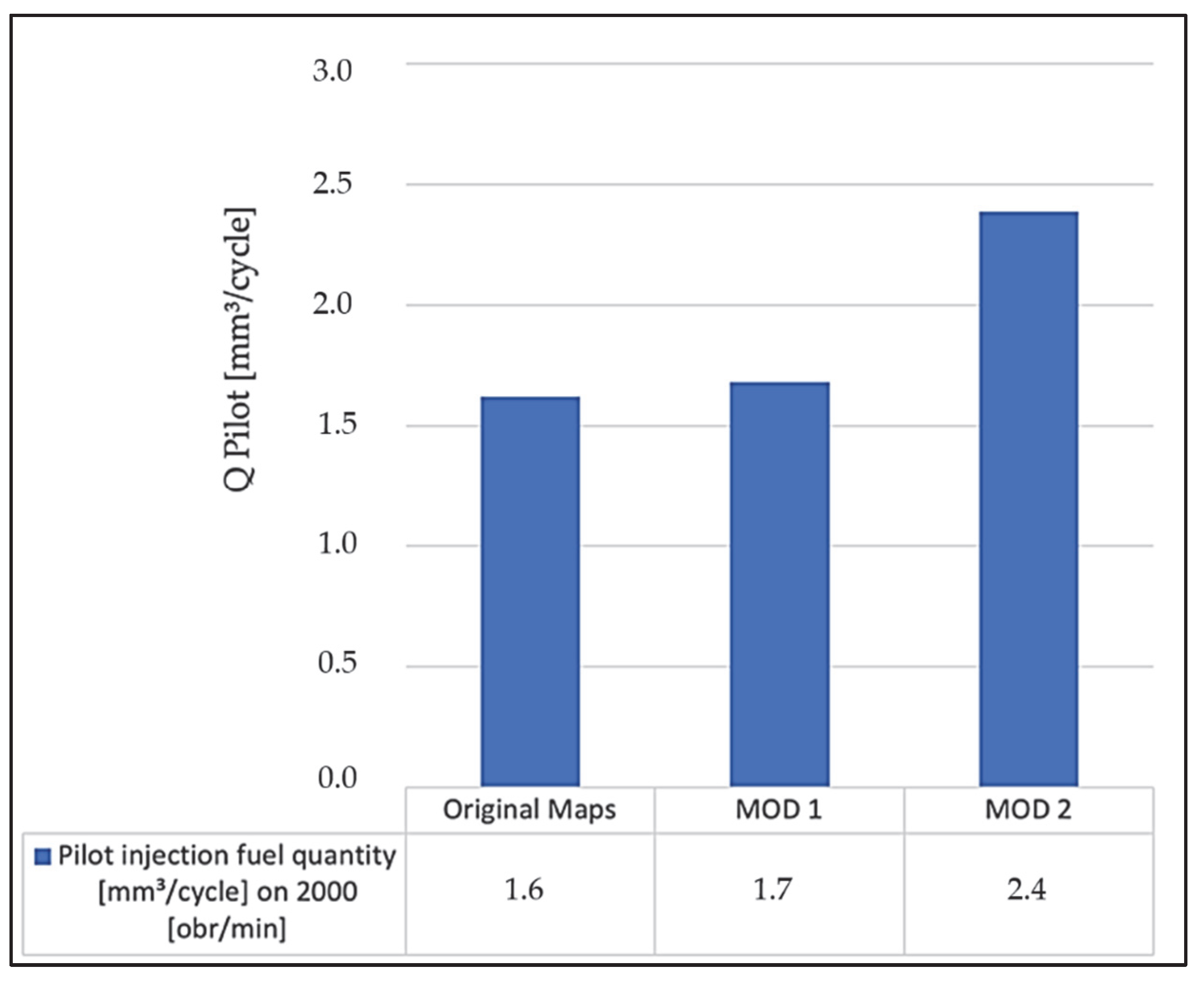
As a result of the modifications, changes in the amount of total fuel injected per engine cycle were noted, as shown in Figure 11. The lowest value of 42.9 mm3/cycle was observed after MOD2. The recorded increase in the pilot injection amount value to 2.4 mm3/cycle after MOD2 is shown in Figure 12, which represented differences of 0.8 mm3/cycle compared to the serial maps. MOD1 did not affect the amount of pilot injection.
The modifications introduced affected the increase in combustion pressure after both pilot injections. A significant change was observed in the parameters of the auto-ignition delay angle (τ) and the rate of combustion pressure build-up (Table 4). The above research confirms the wide range of possibilities for testing a vehicle fueled by different fuels, including the possibility of adapting the control software to the tested fuel.

5. Conclusions

Diesel engines are primarily built to run on diesel fuel. The ECU is tuned for this power source. Using a fuel other than diesel causes changes in the combustion process, which the controller often interprets as an error. Hence, there is a need to interfere with the ECU maps, adjusting the different areas to the fuel under test.
Accelerating the angle of onset of the first pre-injection (MOD2) by 4° from the factory setting increased the pilot injection rate to 2.4 mm3/cycle, an increase of 0.8 mm3/cycle. MOD1 did not significantly affect the pilot injection dose, the difference being 0.1 mm3/cycle. The introduced change of MOD1 and MOD2 affected the increase in combustion pressure after both pilot injections and amounted to 13.61 MPa and 14.74 MPa, respectively, which was an increase of 0.56 MPa and 0.69 MPa compared to the measurement at the factory settings. The auto-ignition delay angle (τ) increased for MOD1 28.38 deg and for MOD2 28.42 deg compared to 26.18 deg at the factory settings. Combustion pressure build-up rates for MOD1 and MOD2 were 0.619 MPa/deg and 0.766 MPa/deg, compared to 0.447 MPa/deg at nominal settings.
The presented stand allows testing a diesel engine fueled by various liquid and gaseous fuels. In addition, there is the possibility of extensive interference with the ECU, as shown in the example of injector control. Control tests of the vehicle can be performed in the conditions of a chassis dynamometer as well as in road conditions.

Author Contributions

D.T., R.L., P.S., Ł.Z., M.T., W.L. and P.L.—signed the experiments, analyzed the experimental data, made figures, and participated in the preparation of the manuscript, wrote the part of the manuscript. D.T., R.L., P.S., Ł.Z., M.T., W.L. and P.L.—conceived the concept of the studies, wrote the main part of the manuscript, and supervised the studies and participated in the manuscript preparation, signed the experiments, analyzed the experimental data, made figures. All authors have read and agreed to the published version of the manuscript.

Funding

The project/research was financed in the framework of the project Lublin University of Technology-Regional Excellence Initiative, funded by the Polish Ministry of Science and Higher Education (contract No. 030/RID/2018/19).

Acknowledgments

The authors would like to thank Magic Motorsport for its support in organizing the test bed equipment.

Conflicts of Interest

The authors declare no conflict of interest.

References

  1. Williams, A. Fundamentals of oil combustion. Prog. Energy Combust. Sci. 1976, 2, 167–179. [Google Scholar] [CrossRef]
  2. Strayer, R.C.; Blake, J.A.; Craig, W.K. Canola and high erucic rapeseed oil as substitutes for diesel fuel: Preliminary tests. J. Am. Oil Chem. Soc. 1983, 60, 1587–1592. [Google Scholar] [CrossRef]
  3. Babu, A.K.; Devaradjane, G. Vegetable oils as fuel for diesel engines: An overview. In Proceedings of the ASME International Mechanical Engineering Congress and Exposition, New Orleans, LA, USA, 17–22 November 2002; American Society of Mechanical Engineers (ASME): New York, NY, USA, 2002; Volume 3, pp. 313–318. [Google Scholar]
  4. Luise, L. Particulate Emission from Gasoline Direct Injection Engine. In Engine Exhaust Particulates; Springer: Berlin/Heidelberg, Germany, 2019; pp. 215–237. [Google Scholar]
  5. Vicentea, G.; Bautistaa, L.F.; Rodrígueza, R.; Gutiérreza, J.; Sádabaa, I.; Ruiz-Vázquezb, R.M.; Torres-Martínez, S.; Garre, V. Biodiesel production from biomass of an oleaginous fungus. Biochem. Eng. J. 2009, 48, 22–27. [Google Scholar] [CrossRef]
  6. Hamasaki, K.; Tanaka, Y.; Nakamura, T.; Takaki, T. Effects of Injection System on Performance of a Direct-Injection Diesel Engine with Emulsified Rapeseed Oil Fuels. Trans. Japan Soc. Mech. Eng. Ser. B 1995, 61, 339–343. [Google Scholar] [CrossRef]
  7. Moser, F.; Schloegl, H.; Wiesbauer, H. Traktorbetrieb mit rapsmethylester. Erdöl Erdgas Kohle/EKEP 1991, 107, 221–227. [Google Scholar]
  8. Hemmerlein, N.; Korte, V.; Richter, H.; Schröder, G. Performance, exhaust emissions and durability of modern diesel engines running on Rapeseed Oil. SAE Trans. 1991, 100, 400–415. [Google Scholar]
  9. Elsbett, K.; Elsbett, L.; Elsbett, G.; Behrens, M. New development in D.I. diesel engine technology. In Proceedings of the Society of Automotive Engineers international congress and exposition, Detroit, MI, USA, 27 February–3 March 1989. SAE Technical Papers 890134. [Google Scholar]
  10. Ziejewski, M.; Kaufman, K.R.; Schwab, A.W.; Pryde, E.H. Diesel engine evaluation of a nonionic sunflower oil-aqueous ethanol microemulsion. J. Am. Oil Chem. Soc. 1984, 61, 1620–1626. [Google Scholar] [CrossRef]
  11. Gorski, K.; Smigins, R. Impact of ether/ethanol and biodiesel blends on combustion process of compression ignition engine. In Proceedings of the Engineering for Rural Development, Jelgava, Latvia, 26–27 May 2011. [Google Scholar]
  12. Vallinayagam, R.; Vedharaj, S.; Yang, W.M.; Lee, P.S.; Chua, K.J.E.; Chou, S.K. Combustion performance and emission characteristics study of pine oil in a diesel engine. Energy 2013, 57, 344–351. [Google Scholar] [CrossRef]
  13. Lapuerta, M.; Herreros, J.M.; Lyons, L.L.; García-Contreras, R.; Briceño, Y. Effect of the alcohol type used in the production of waste cooking oil biodiesel on diesel performance and emissions. Fuel 2008, 87, 3161–3169. [Google Scholar] [CrossRef]
  14. Longwic, R.; Sander, P.; Zdziennicka, A.; Szymczyk, K.; Jańczuk, B. Combustion process of canola oil and n-hexane mixtures in dynamic diesel engine operating conditions. Appl. Sci. 2020, 10, 80. [Google Scholar] [CrossRef] [Green Version]
  15. Bortel, I.; Vávra, J.; Takáts, M. Effect of HVO fuel mixtures on emissions and performance of a passenger car size diesel engine. Renew. Energy 2019, 140, 680–691. [Google Scholar] [CrossRef]
  16. Fuć, P.; Merkisz, J.; Lijewski, P.; Bajerlein, M.; Ziółkowski, A.; Rymaniak, Ł.D. Badania emisji spalin w teście NEDC wykonane na dynamicznym silnikowym stanowisku hamulcowym. Combust. Engines 2013, 52, 701–707. [Google Scholar]
  17. Hetmańczyk, I.; Hepner, W.; Halicki, R. Modyfikacja charakterystyki zewnętrznej silnika o zapłonie samoczynnym poprzez zmianę parametrów wtrysku paliwa. Inżynieria Rol. 2013, 17, 79–89. [Google Scholar]
  18. Longwic, R.; Sen, A.K.; Górski, K.; Lotko, W.; Litak, G. Cycle-to-cycle variation of the combustion process in a diesel engine powered by different fuels. J. Vibroeng. 2011, 13, 120–127. [Google Scholar]
  19. Rakopoulos, C.D.; Giakoumis, E.G. Diesel Engine Transient Operation: Principles of Operation and Simulation Analysis; Springer: Berlin/Heidelberg, Germany, 2009. [Google Scholar]
  20. Rakopoulos, C.D.; Giakoumis, E.G. Review of thermodynamic diesel engine simulations under transient operating conditions. SAE Trans. 2006, 115, 467–504. [Google Scholar]
  21. Bazari, Z. Diesel exhaust emissions prediction under transient operating conditions. SAE Trans. 1994, 100, 1004–1019. [Google Scholar]
  22. Rajak, U.; Nashine, P.; Verma, T.N. Effect of spirulina microalgae biodiesel enriched with diesel fuel on performance and emission characteristics of CI engine. Fuel 2020, 268, 117305. [Google Scholar] [CrossRef]
  23. Nag, S.; Sharma, P.; Gupta, A.; Dhar, A. Experimental study of engine performance and emissions for hydrogen diesel dual fuel engine with exhaust gas recirculation. Int. J. Hydrog. Energy 2019, 44, 12163–12175. [Google Scholar] [CrossRef]
  24. Dey, S.; Reang, N.M.; Majumder, A.; Deb, M.; Das, P.K. A hybrid ANN-Fuzzy approach for optimization of engine operating parameters of a CI engine fueled with diesel-palm biodiesel-ethanol blend. Energy 2020, 202, 117813. [Google Scholar] [CrossRef]
  25. Hassan, A.A.; Elwardany, A.E.; Ookawara, S.; Ahmed, M.; El-Sharkawy, I.I. Integrated adsorption-based multigeneration systems: A critical review and future trends. Int. J. Refrig. 2020, 116, 129–145. [Google Scholar] [CrossRef]
  26. Das, B.; Pai, A.; Kini, C.R. Oxy-hydrogen hybrid diesel engine. ARPN J. Eng. Appl. Sci. 2020, 15, 1063–1068. [Google Scholar]
  27. Ibrahim, H.; Younès, R.; Basbous, T.; Ilinca, A.; Dimitrova, M. Optimization of diesel engine performances for a hybrid wind-diesel system with compressed air energy storage. Energy 2011, 36, 3079–3091. [Google Scholar] [CrossRef]
  28. Zhang, S.; Wu, Y.; Hu, J.; Huang, R.; Zhou, Y.; Bao, X.; Fu, L.; Hao, J. Can Euro V heavy-duty diesel engines, diesel hybrid and alternative fuel technologies mitigate NOX emissions? New evidence from on-road tests of buses in China. Appl. Energy 2014, 132, 118–126. [Google Scholar] [CrossRef]
  29. Valverde, V.; Mora, B.A.; Clairotte, M.; Pavlovic, J.; Suarez-Bertoa, R.; Giechaskiel, B.; Astor, C.; Fontaras, G. Emission factors derived from 13 Euro 6b light-duty vehicles based on laboratory and on-road measurements. Atmosphere 2019, 10, 243. [Google Scholar] [CrossRef] [Green Version]
  30. Longwic, R.; Sander, P. The course of combustion process under real conditions of work of a traction diesel engine supplied by mixtures of canola oil containing n-hexane. In Proceedings of the IOP Conference Series: Materials Science and Engineering, Nanjing, China, 17–19 August 2018; Volume 421. [Google Scholar]
  31. European Automobile Manufacture Association; Polski Związek Przemysłu Motoryzacyjnego. W Kierunku Zeroemisyjnej Mobilności. In Czynniki Determinujące Rozwój Napędów Alternatywnych w Samochdoach Osobowych i Dostawczych w Uni Europejskiej; ACEA: Brussels, Belgium, 2020. [Google Scholar]
  32. Lotko, W.; Longwic, R.; Swat, M. The Effect of Rape Oil—Diesel Oil Mixture Composition on Particulate Matter Emission Level in Diesel Engine; SAE Technical Paper 2001-01-3388; SAE International: Warrendale, PA, USA, 2001. [Google Scholar] [CrossRef]
  33. Górski, K.; Smigins, R.; Longwic, R. Research on physico-chemical properties of diethyl ether/linseed oil blends for the use as fuel in diesel engines. Energie 2020, 13, 6564. [Google Scholar] [CrossRef]
  34. Longwic, R.; Nieoczym, A.; Kordos, P. Evaluation of the combustion process in a spark-ignition engine based on the unrepeatability of the maximum pressure. In IOP Conference Series: Materials Science and Engineering; IOP Publishing: Bristol, UK, 2018. [Google Scholar]
  35. Sonachalam, M.; Manieniyan, V. Optimization of critical angle, distance and flow rate of secondary fuel injection in DI diesel engine using computational fluid dynamics. SN Appl. Sci. 2021, 3, 126. [Google Scholar] [CrossRef]
  36. Sonachalam, M.; Manieniyan, V. Comparative experimental analysis on dual fuel with biodiesel-acetylene in reactivity controlled compression ignition engine. Int. J. Ambient. Energy 2022. [Google Scholar] [CrossRef]
  37. Manieniyan, V.; Sukumar, V.; Senthilkumar, R.; Sivaprakasam, S. Emission reduction using biodiesel blends with nano-additives and reformed exhaust gas recirculation (REGR) in DI diesel engine. Int. J. Ambient. Energy 2019, 43, 641–647. [Google Scholar] [CrossRef]
  38. Manieniyan, V.; Senthilkumar, R.; Sukumar, V. Study on diesel engine characteristics using multi-walled carbon nanotubes blended thermal cracked vegetable oil refining waste, Materials today. Proceedings 2021, 37, 3665–3672. [Google Scholar]
  39. Sonachalam, M.; Paul Pandian, P.; Manieniyan, V. Emission reduction in diesel engine with acetylene gas and biodiesel using inlet manifold injection. Clean Technol. Environ. Policy 2020, 22, 2177–2191. [Google Scholar] [CrossRef]
  40. Sander, P.; Longwic, R.; Zdziennicka, A.; Jańczuk, B.; Szymczak, K. The Use of Canola Oil, n-Hexane, and Ethanol Mixtures in a Diesel Engine. SAE Int. J. Fuels Lubr. 2021, 14, 123–138. [Google Scholar] [CrossRef]
  41. Longwic, R.; Sander, P.; Tatarynow, D. Ecological aspects of using mixtures of canola oil with n-hexane in diesel engine. Combust. Engines 2022, 61, 3. [Google Scholar] [CrossRef]
  42. Dziubiński, M.; Siemionek, E.; Drozd, A.; Żur, P.; Ścierka, T.; Tatarynow, D. Analysis of the impact of damage to the injection system on the emission of toxic substances in a spark-ignition internal combustion engine. Combust. Engines. 2019, 58, 112–118. [Google Scholar] [CrossRef]
  43. Longwic, R.; Sander, P.; Zdziennicka, A.; Jańczuk, B.; Szymczak, K. Modification of Canola Oil Physicochemical Properties by Hexane and Ethanol with Regards of Its Application in Diesel Engine. Energies 2021, 14, 4469. [Google Scholar] [CrossRef]
  44. Elsbett. G. Future Trends of Biofuel Engines with Elsbett-Technology; Institut Penyelidikan Minyak Kelapa Sawit Malaysia: Selangor, Malaysia, 1995. [Google Scholar]
  45. Operating Instructions for the Chassis Dynamometer DF4FS-HLS. Available online: https://www.dimsport.it/en/dyno/dynorace-4wd-hls/ (accessed on 1 September 2022).
  46. Available online: https://diglib.tugraz.at/download.php?id=576a771744992&location=browse (accessed on 1 September 2022).
  47. Available online: https://www.avl.com/?avlregion=GLOBAL&groupId=10138&lang=en_US (accessed on 1 September 2022).
  48. Available online: https://www.evc.de/ftp/winols/WinOLS%20HelpEn.pdf (accessed on 1 September 2022).
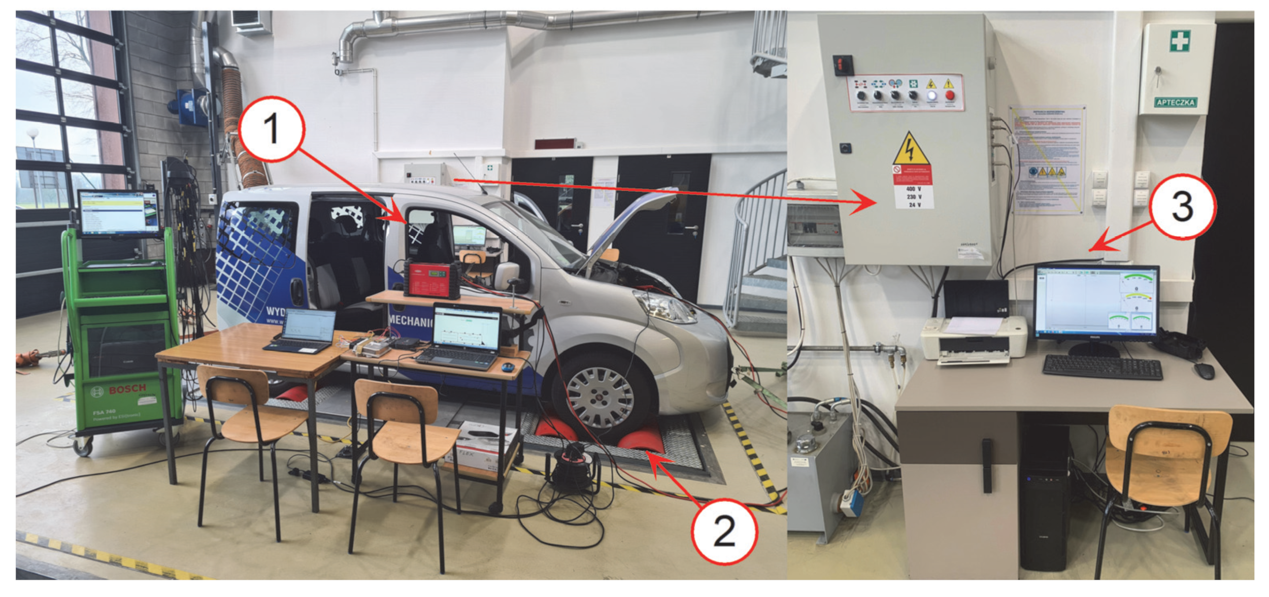
Figure 1. Test stand for testing a vehicle powered by different fuels. 1. Fiat Qubo vehicle under test. 2. DF4FS-HLS chassis dynamometer. 3. Computer with DynoRace software installed along with control cabinet and sensor accessories.
Applsci 12 10683 g001
Figure 2. Control, measuring and recording apparatus: 1. mobile computer with IndiCom software from AVL, V.07 flow meter, FIAT Multiecuscan, 2. Multiecuscan diagnostic interface, 3. Auxiliary fuel system tank with meter from Rotameter company with Multicon CMC-99 Simex module, 4. Engine indexing system and components: (a) AVL IndiMicro 602 measuring module, (b) AVL Universal Pulse Conditioner 389Z01 transducer, (c) AVLGH13P piezoelectric sensor in I cylinder glow plug socket, (d) Current clamps connected to I cylinder injector, (e) Induction engine speed sensor, 5. Diesel engine meeting EURO 5 exhaust gas standards.
Applsci 12 10683 g002
Figure 3. Read-write-programming apparatus consisting of 1. FLEX MASTER from Magic Motorsport, 2. Fronius Acctiva Professional Flash 70A power supply, 3. WinOLS Version 4.51 software, 4. Mobile computer with Flex and WinOLS software installed. 5. a copy of the ECU controller from the Fiat Qubo.
Applsci 12 10683 g003
Figure 4. Series map SOI.
Applsci 12 10683 g004
Figure 5. Modified map SOI.
Applsci 12 10683 g005
Figure 6. Injection control series.
Applsci 12 10683 g006
Figure 7. Injection control after modifications.
Applsci 12 10683 g007
Figure 8. The waveform of the main injection and combustion parameters (Original maps), i.e., the rate of heat of combustion (Q1), the amount of heat of combustion (L1), the combustion pressure (PCYL1), the rate of combustion pressure buildup (PCYL1_der) and the injector control signal (INJ_SIG1)—under established engine operating conditions, engine speed 2000 [rpm] and load 130 [Nm].
Applsci 12 10683 g008
Figure 9. The waveform of the main injection and combustion parameters (MOD1), i.e., the rate of heat of combustion (Q1), the amount of heat of combustion (L1), the combustion pressure (PCYL1), the rate of combustion pressure build-up (PCYL1_der) and the injector control signal (INJ_SIG1)—under the established engine operating conditions, engine speed 2000 [rpm] and load 130 [Nm].
Applsci 12 10683 g009
Figure 10. The waveform of the main injection and combustion parameters (MOD2), i.e., the rate of heat of combustion (Q1), the amount of heat of combustion (L1), the combustion pressure (PCYL1), the rate of combustion pressure build-up (PCYL1_der) and the injector control signal (INJ_SIG1)—under the established engine operating conditions, engine speed 2000 [rpm] and load 130 [Nm].
Applsci 12 10683 g010
Figure 11. Total fuel quantity on 2000 RPM and 130 Nm.
Applsci 12 10683 g011
Figure 12. Pilot injection fuel quantity on 2000 RPM and 130 Nm.
Applsci 12 10683 g012
Table 1. Main characteristics of Fiat Qubo vehicle used for the tests.
ParameterCharacteristics
NameFiat Qubo
Production year2015
Engine capacity1248 cm3
Cylinder number and arrangement4, in line
Cylinder diameter69.6 mm
Piston stroke82 mm
Compression ratio16.8: 1
Max power55 kW CEE/75 KM CEE
Max torque190 Nm CEE/kgm CEE
Idle speed850 ± 20 RPM
Rotational speed at maximum torque1500 RPM
Injection system/fuel supplyCommon Rail/diesel
Exhaust gas cleaning systemsEGR, DPF
Table 2. Technical data of the roller dynamometer DF4FS-HLS.
ParameterCharacteristics
Maximum axle load2500 kg
Maximum speed300 km/h
Maximum power on accelerated axle400 kW
Maximum power on continuously loaded axle300 kW
Tractive force7500 N
Measurement accuracy+/−2%
Table 3. Numbering of the changes carried out.
Modification NumberChange Parameters
ORIOriginal maps
MOD1(+)4 deg PREinj (+)2 deg MAINinj
MOD2(+)4 deg PREinj (+)2 deg MAINinj (+)1 mm3 PREinj
Table 4. Parameters for 2000RPM and 130Nm.
Modification NumberParameters for 2000 [rpm] and 130 [Nm]
SOISOCτIMEPPCYL1MAXPCYL1_der
[deg][deg][deg][MPa][MPa]MPa/deg
Original−34−7.8526.181.8813.050.447
MOD1−38−9.5528.422.013.740.619
MOD2−38−9.6028.381.9914.610.766
Publisher’s Note: MDPI stays neutral with regard to jurisdictional claims in published maps and institutional affiliations.