Article

Conceptual Design of a Compact Divertor Heat Load Simulation Device: HIT-PSI

1
School of Physics, Harbin Institute of Technology, Harbin 150001, China
2
School of Electrical Engineering and Automation, Harbin Institute of Technology, Harbin 150001, China
3
Laboratory for Space Environment and Physical Sciences, Harbin Institute of Technology, Harbin 150001, China
*
Author to whom correspondence should be addressed.
Appl. Sci. 2022, 12(20), 10501; https://doi.org/10.3390/app122010501
Submission received: 21 September 2022 / Revised: 2 October 2022 / Accepted: 11 October 2022 / Published: 18 October 2022
(This article belongs to the Special Issue Plasma Technology and Its Applications)

Abstract

:
Linear plasma devices have been increasingly applied in investigating plasma–surface interaction (PSI) processes and divertor/scraped-off-layer (D/SOL) physics because of their economy, flexibility, and expandability. However, only a few existing linear plasma devices are able to obtain high heat and particle fluxes. In this work, we report a compact superconducting linear device, with its scientific goals and specific design methods, at Harbin Institute of Technology (HIT), HIT-PSI, capable of implementing an extreme plasma environment with beams of a long discharge pulse, as well as high heat and particle fluxes in the future fusion reactor regime of ITER/CFETR-like parameters. A five-coil integrated superconducting magnet is designed to generate a >2.0 Tesla steady-state magnetic field for confining a long pulse plasma beam with a density of >1020 m−3 produced by a cascaded arc plasma source. With a pump set of 2500 L/s and a water-cooled target system with bias voltage, it is expected to obtain high-density and low-temperature plasma beams with a heat flux of over 10 MW/m2. Subsystems of the platform, including the plasma source, superconducting magnets, vacuum system, and target holder system, are described in detail. In addition, the function and performance of the platform are numerically simulated and represented by SOLPS-ITER code to predict the laboratory simulation results.

1. Introduction

In tokamak operations, plasma–surface interaction (PSI) processes under extreme conditions have profound impacts on operational safety, performance metrics, and economical efficiency of fusion reactors, and have become one of the primary foci of fusion studies [1,2,3]. High heat and particle fluxes reaching plasma-facing components (PFCs) will cause erosion and tritium retention of materials [4]. Therefore, understanding and exploring the PSI mechanism is crucial to the realization of controlled nuclear fusion.
However, divertors in future fusion reactors such as ITER and CFETR are subject to extreme long-pulse high heat/particle fluxes, far beyond the parameters of existing tokamaks [5,6]. The performance of PFCs under such high-parameter plasma bombardments is thus an unknown territory. Various lab simulation devices for divertor plasmas have been developed for studying PSIs. Among them, linear plasma devices are the most widely adopted worldwide due to their economy, flexibility, and expandability, as well as their advantages as diagnostic test platforms. For example, a steady-state linear plasma device of PISCES-B is capable of testing radioactive and toxic materials such as Be [7,8]; another divertor simulator facility, NAGDIS-II, is applied in high-density plasma detachment studies [9]; and a device at Sichuan University with similar functions, SCU-PSI, is applied in PSI investigations of liquid materials [10,11]. The above-mentioned and many more established linear plasma devices have greatly advanced PSI research, along with diagnostic techniques, plasma sources, and plasma physics of low-temperature plasma [12,13,14,15,16,17]. There are nevertheless only a few devices, including Magnum-PSI and MPEX, reported to be capable of simulating the divertor heat load in ITER-like steady-state operations. Magnum-PSI is an integrated linear plasma device with the most comprehensive performance in the world, where a steady-state particle flux of up to 1025 m2s−1 and a steady-state heat flux of up to 50 MW/m2 [18,19,20] can be achieved. MPEX [21] is, on the other hand, designed for performing neutron-related materials testing experiments.
To experimentally simulate the extreme divertor plasma environment with a heat flux exceeding 10 MW/m2 and a particle flux over 1024 m−2s−1 in steady-state, a linear divertor plasma simulator for PSI, namely HIT-PSI, is designed and constructed at Harbin Institute of Technology. In this paper, the conceptual design of this low-cost and compact linear plasma device is reported, with numerical validation of its planned functions and performance prediction.
The layout of the paper is as follows. After the Introduction, Section 2 goes into the details of the design and its scientific goals, as well as displaying the specifics of each component of the device. The expected parameters, functions, and performances of the device are predicted with numerical simulation in Section 3. The work ends with a summary in Section 4.

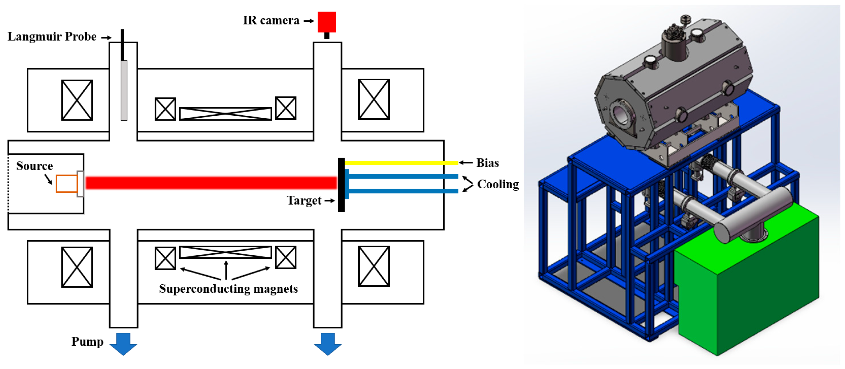
2. Designs of the Device and Its Sub-Systems

2.1. Scientific Objectives

HIT-PSI is designed and constructed for experimentally simulating the extreme plasma environment with an intensive heat flux over 10 MW/m2, and a high-density particle flux over 1024 m−2s−1 in steady-state, for divertor physics studies, particularly with detached mode plasma parameters in ITER-like future fusion reactors, such as CFETR [5,22]. The major scientific objectives of the device are listed as follows:
  • To investigate strongly coupled PSI regimes under high fluxes close to extreme first-wall plasma conditions similar to that of ITER-like reactors;
  • To examine the effects of chemistry and atomic physics in such boundary plasmas with high densities and low temperatures;
  • To explore low-temperature plasma diagnostic technologies under the D-SOL plasma and magnetic field conditions;
  • To develop high-parameter plasma source technologies in a strong magnetic field environment.
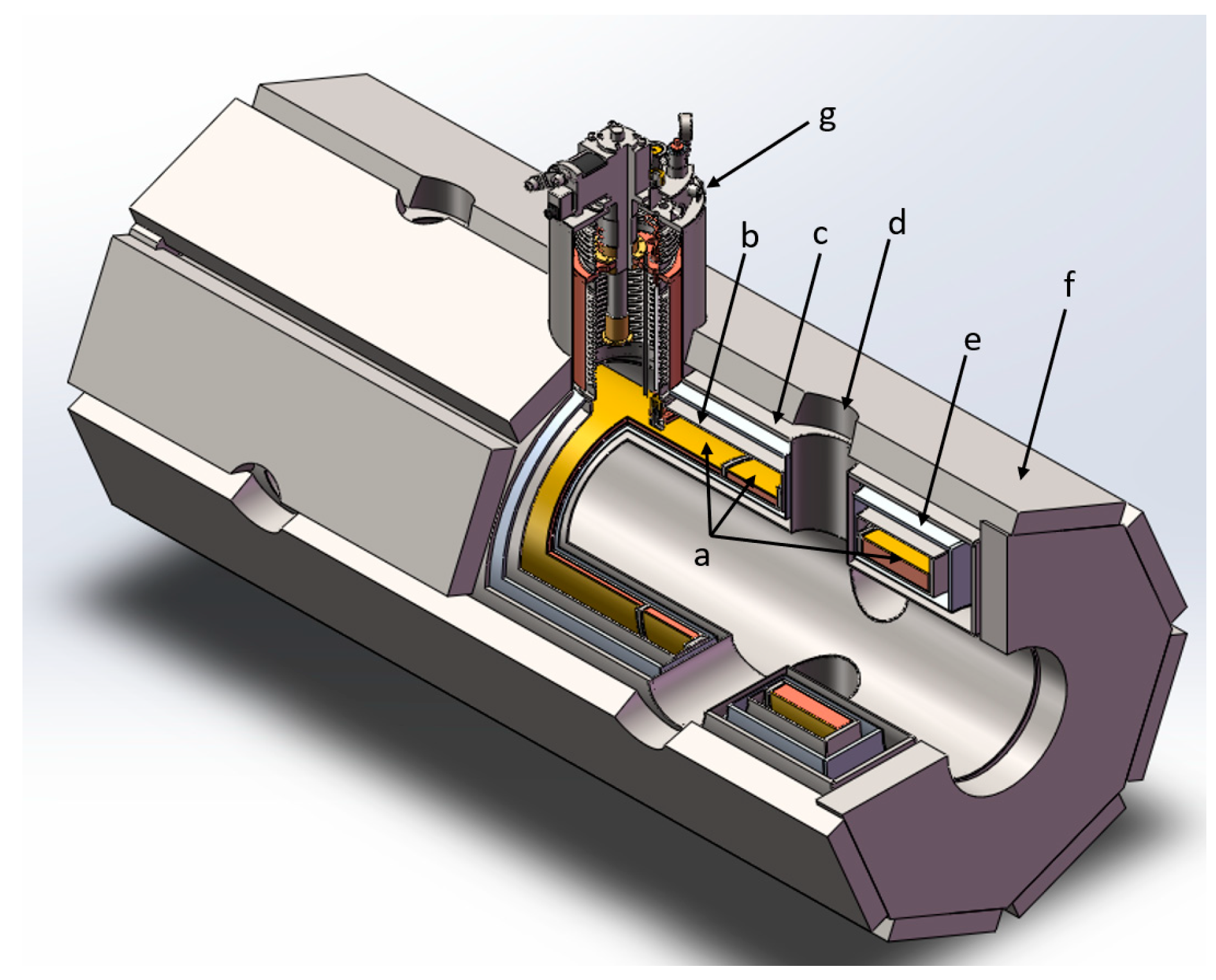
HIT-PSI is schematically depicted in Figure 1. It mainly consists of a cascaded arc plasma source, a superconducting magnet, a target holder, as well as a vacuum, and other related auxiliary subsystems. The design specifications of HIT-PSI are listed in Table 1, where plasma parameters of serval typical linear plasma simulator devices and the ITER-like divertor are also represented for comparison.

2.2. Plasma Source

Both RF and cascaded arc sources have been experimentally demonstrated to satisfy the demand for the plasma source of a linear plasma device with ITER-like high heat flux by MPEX and Magnum-PSI [20,21]. However, the RF sources are typically of a lower density, and thus other assisting heating means are necessary to achieve a high plasma temperature. It is then a great technical challenge with notable cost. By contrast, cascaded arc sources are more advantageous since they can generate higher-density plasmas with a temperature of up to several eVs without extra heating. Consequently, we applied cascaded arc sources in HIT-PSI.
The cascaded arc plasma source was invented in the 1960s by Maecker [25] and first constructed and optimized with three channels in 2009 [26] at Eindhoven University of Technology. It has also been experimentally explored at Harbin Institute of Technology for years [27]. The three-channel cascaded arc plasma source and its anode flange are shown in Figure 2. Three to five cascade plates made of pure copper are sandwiched between the anode flange and separated by Boron nitride gaskets, with water cooling. Molybdenum rings are inserted into the cascade plates to face the plasma. Three cathode pins made of tungsten are put on top. For argon gas discharge with no magnetic field, each current channel can reach 160 A, and the plasma density may exceed 1019 m−3.
Multiple channels of the cascaded arc plasma cannot increase the plasma beam density, especially when a strong magnetic field exists to limit the mix of separated channel beams, resulting in an uneven plasma density. Therefore, either a single-channel or a three-channel cascaded arc plasma source has been applied to meet the requirement of various features of the plasma beam in different operation scenarios.
The water-cooling architecture of cascade plates is a key factor for the long-term steady-state operation of the arc source. An optimized waterway designed by COMSOL Multiphysics is shown in Figure 3, which is efficient in terms of heat dissipation and water pressure reduction. Complex waterway designs can be achieved to maximize water cooling efficiency by diffusion welding.

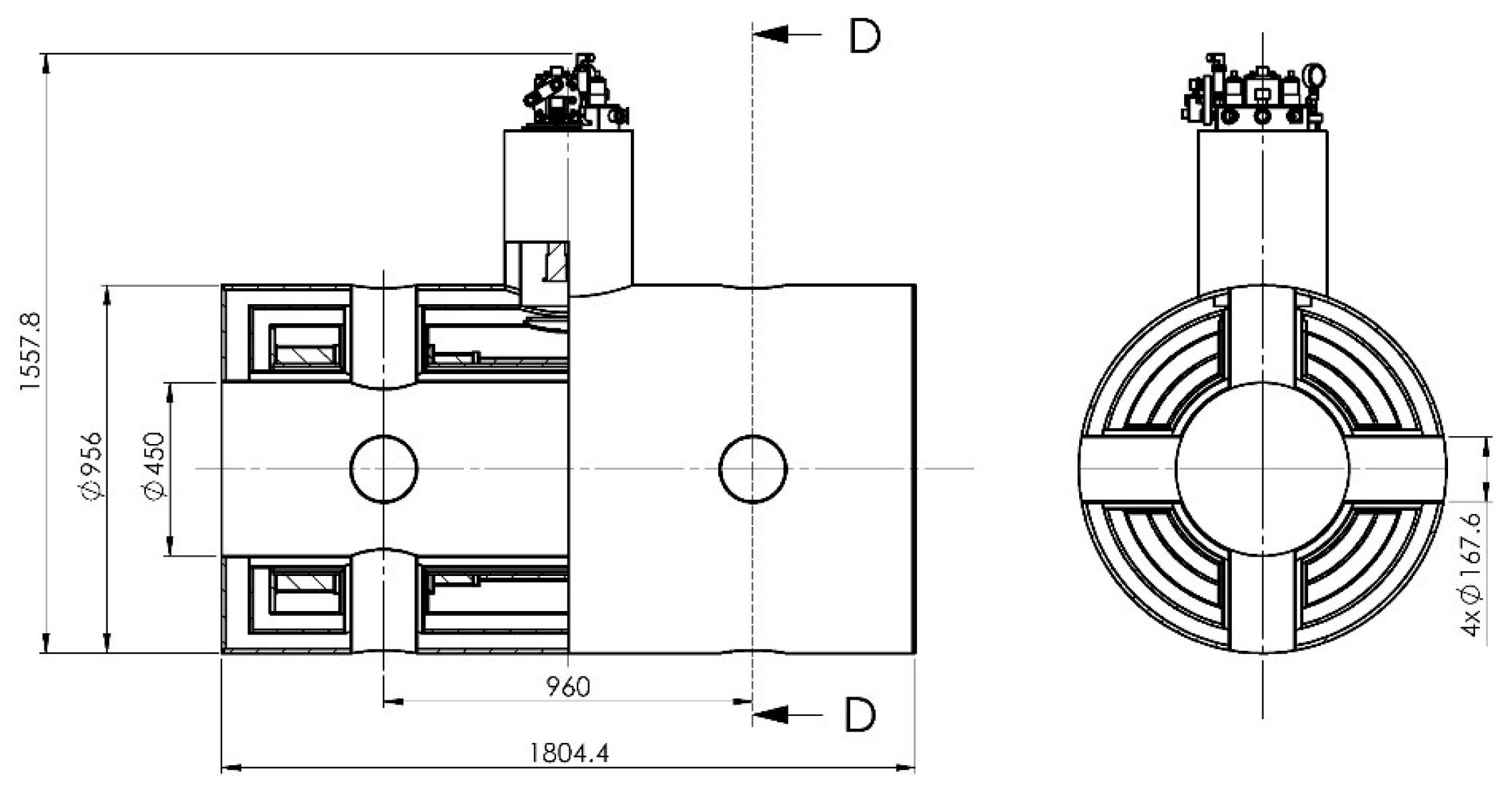
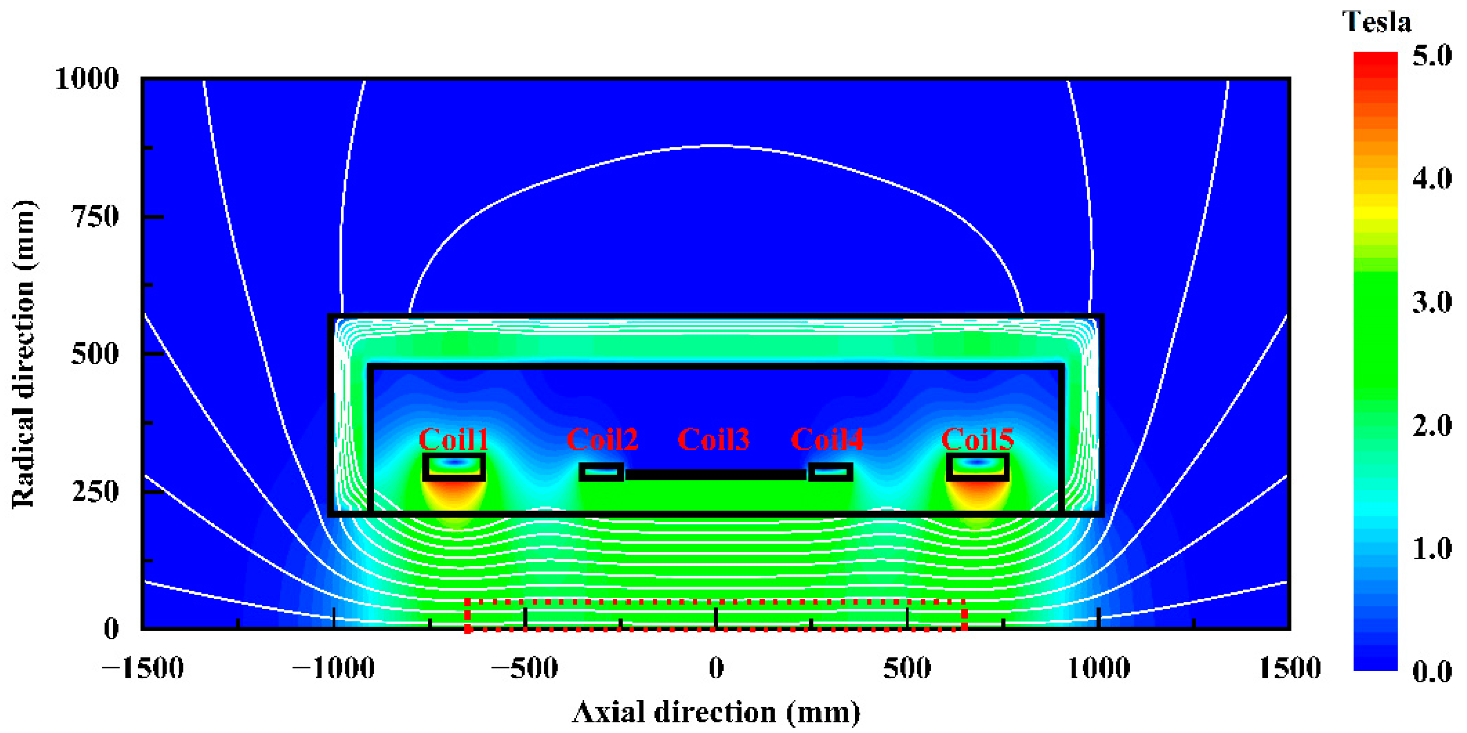
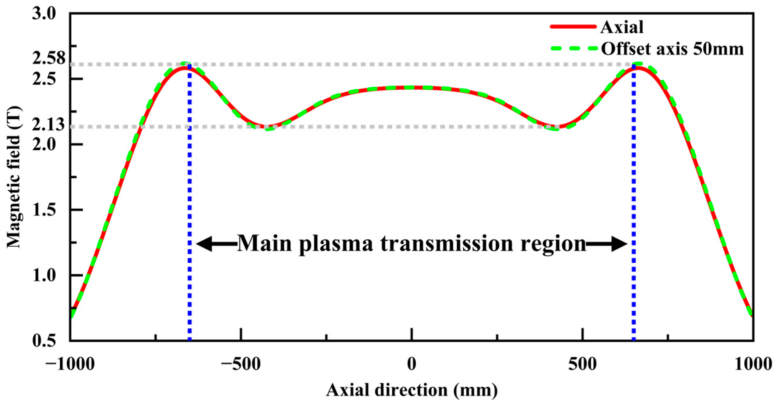
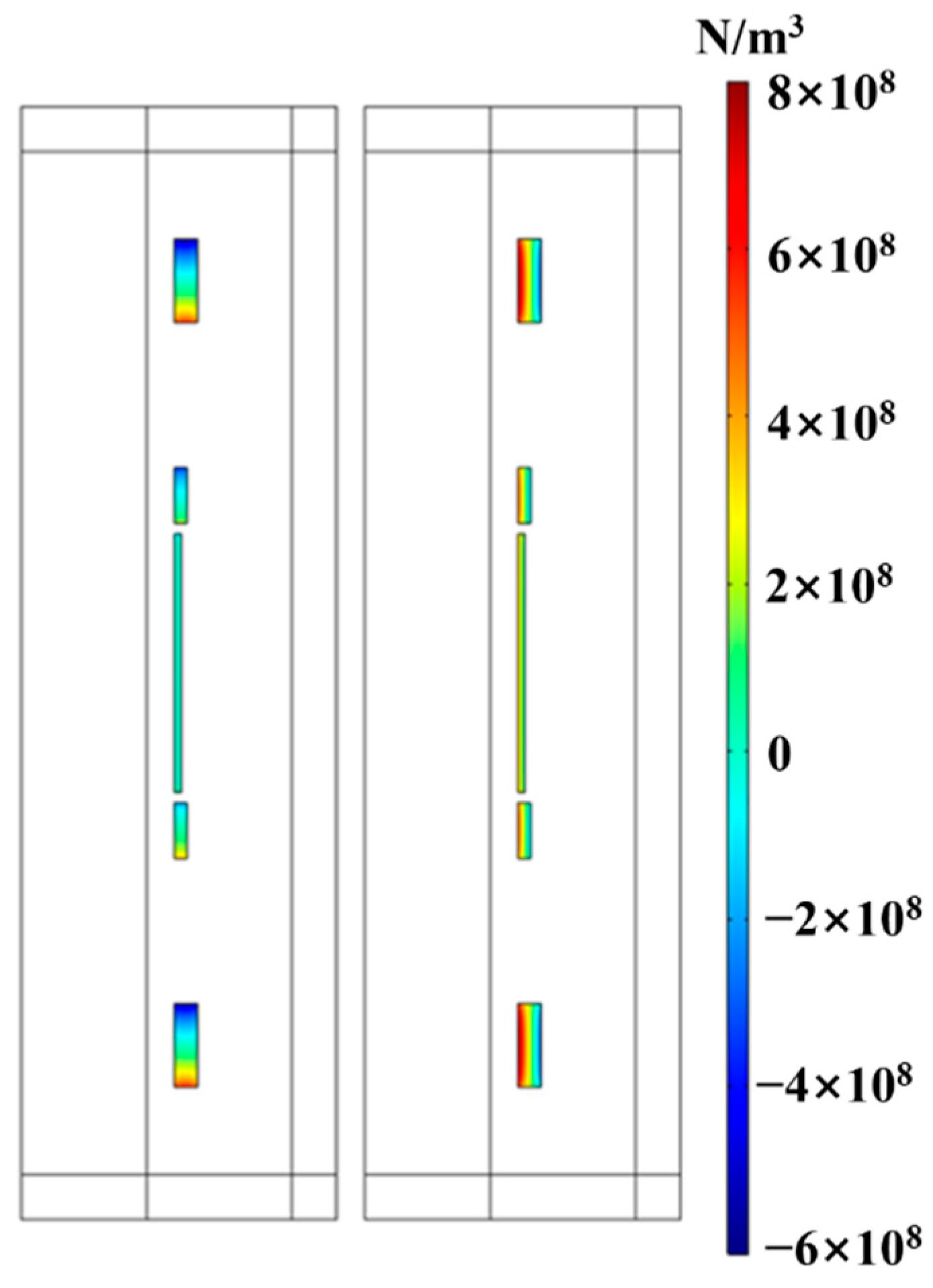
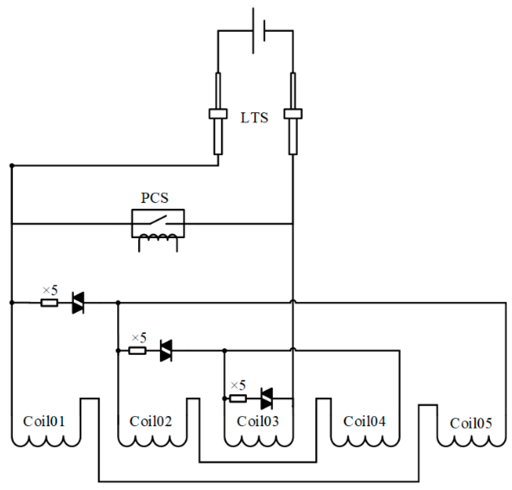
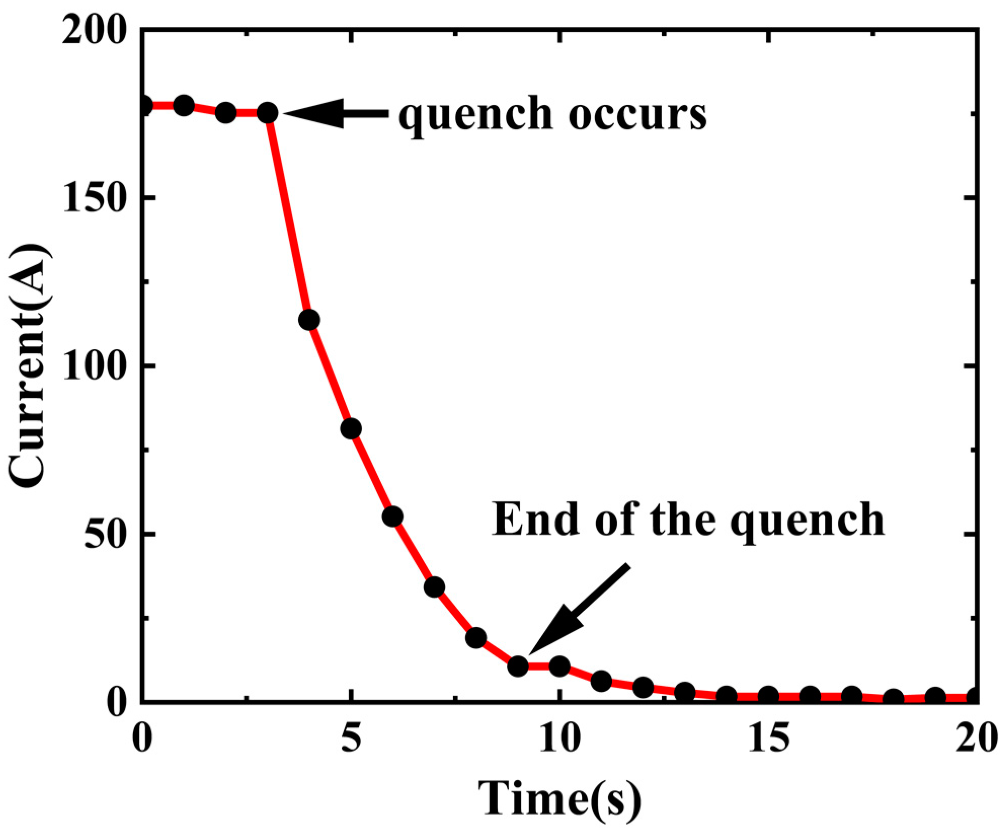
2.3. Superconducting Magnets

In a linear plasma device for PSI research, the role of the magnetic field is to confine the radial diffusion of the plasma beam and to limit the radius of the sputtered particle rotation to smaller than the re-deposited material sample. Meanwhile, previous experimental results of Magnum-PSI showed that the application of a strong magnetic field could improve the performance of the arc plasma source, where a higher ionization rate and a more effective rise of the plasma density and temperature approaching the target plate can be achieved [23,28]. When the confinement magnetic field of the source reaches a ~Tesla level, the heat flux can reach ~10 MW/m2. Thus, a superconducting magnet subsystem to generate a steady-state strong magnetic field is essential.
The construction of superconducting magnets may take a major share of the budget. Therefore, the design should be well balanced among physical needs, engineering challenges, operating costs, and budget allowed. The design parameters then have to mostly meet the following needs:
  • Safety, which always comes first, including personnel and operational safety needs;
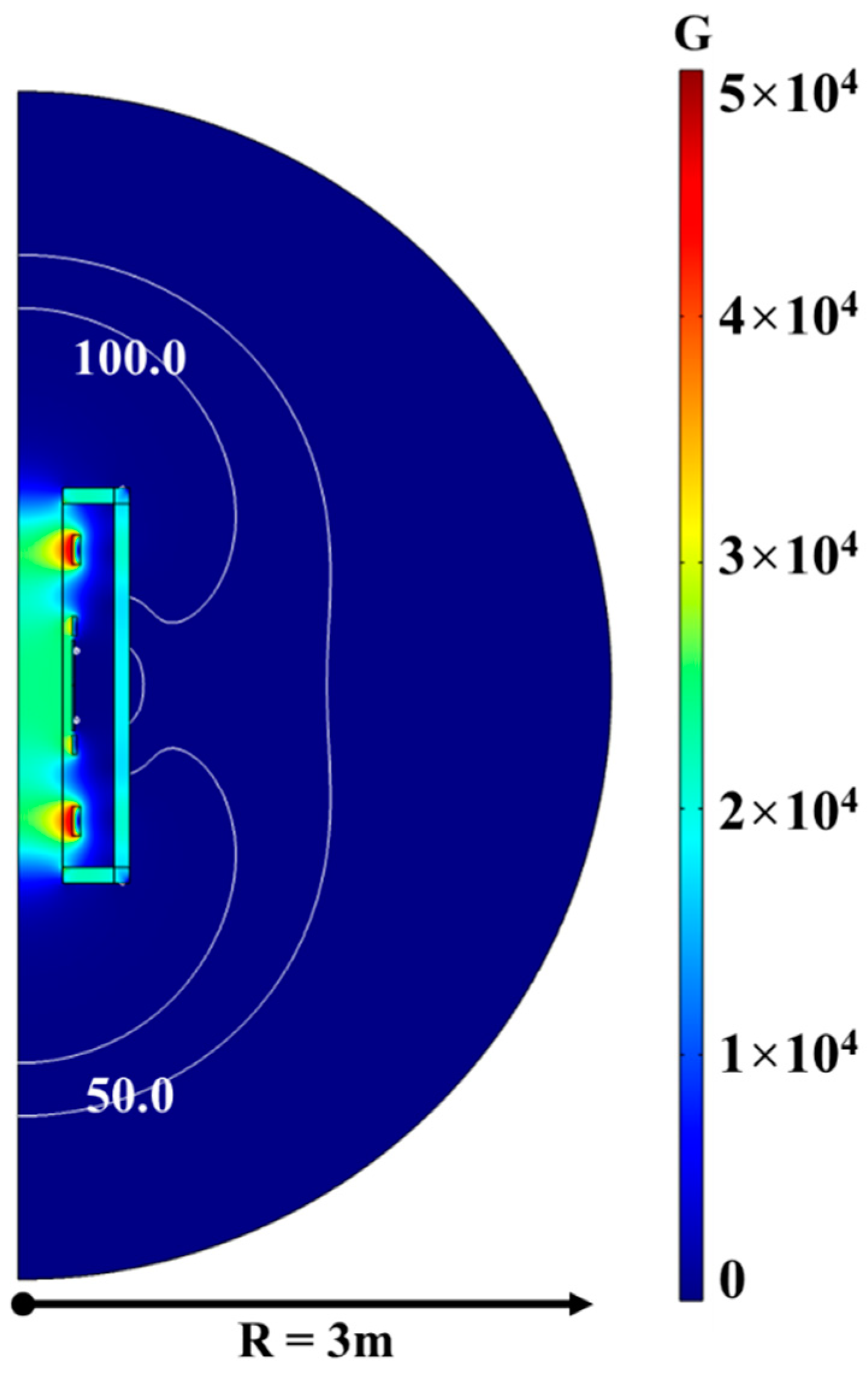
  • An axial magnetic field of >2.0 T with great homogeneity;
  • More than 1000 mm axial distance of beam transmission, for future experimental research with a radial size as large as possible, enough for the vacuum chamber to accommodate the beam;
  • Radial windows left for pumping and diagnostic needs;
  • A fast excitation for experimental flexibility;
  • Also, a low cost for operation, maintenance, and construction.
Taking the above factors into consideration, the superconducting magnet design, shown in Figure 4, adopts an integrated system immersed in a closed cryostat containing liquid helium and directly cooled by a cryocooler to form a zero-boil-off system. Only a tiny amount of liquid helium is needed to keep the steady-state operation of the magnets. The main body of a superconducting magnet is shown in Figure 5, with an inner diameter of 450 mm, a total length of 1804.4 mm, and a total weight of 348.7 kg. In addition, eight radially distributed room temperature ports with a diameter of 167.6 mm for each are reserved for diagnostics and vacuum pump connection.
The major parameters of the superconducting magnet subsystem are listed in Table 2. A total of five solenoid coils are utilized in the superconducting magnet subsystem to ensure the preferred axial homogeneity of the magnetic field with a possibility of flexible modification.
Table 3 is for the coil parameters. The magnetic field distribution generated by the maximum operating current of 275 A is shown in Figure 6 by Comsol 2D axisymmetric modeling. Coils 1 and 5, symmetrically distributed on both sides of Coil 3, have the same parameters. So do Coils 2 and 4. Copper stabilized (Cu/Sc:4) NbTi conductor lines of totally 23.77 km, with an insulated rectangular cross-section of 1.65 × 1.0 mm2 and an insulating layer of 0.04 mm, are adopted. Due to the space left for room temperature bores between Coil Pairs 2/4 and 1/5, Coils 1 and 5 have more layers to improve homogeneity. Both the source and the target are placed near room temperature bores for easy observation and diagnosis. The plasma density of the beam generated by the cascaded arc plasma source exhibits a Gaussian distribution, and the radial full width at the half maximum (FWHM) of the plasma density is less than 50 mm due to the confinement of the strong magnetic field [19]. Moreover, the magnetic field distribution in the main plasma transmission region (enclosed in Figure 6 by red dots), with a length of 1300 mm along the axis and a radius of 50 mm, is illustrated in Figure 7. The average magnetic intensity in this region is 2.33 T, with a field uniformity of ±9.7%.
Furthermore, Table 4 lists the inductance matrix of five coils. To obtain better experimental adaptability, the ramp time of the coil current needs to be minimized. For the excitation voltage distribution of 30.4%/8.1%/20.0%/8.1%/30.4%, the ramp-up time of 32.7 min at 5 volts and 54.5 min at 3 volts is aimed to reduce impacts while still meeting adequate technical standards.
The cryogenic cooling arrangements, including current leads, cryocooler, gas supplement valves, liquid helium injection ports, auxiliary helium interfaces, pressure measurement interfaces, bursting membranes, exhaust valves, and coil protection circuit accessories, are all integrated into the service tower (Figure 4g) located in the upper middle part of the magnet. Current leads are made of REBCO materials. The cryocooler uses an SRDK-415D Sumitomo Gifford-McMahon one with a first-stage cooling capacity of 42 W at 50 K and a second-stage capacity of 1.8 W at 4.2 K, while the estimated heat loss is 1.5 W at 4.2 K.
This superconducting magnet subsystem with a lot of radial windows is a new challenge for design and construction. Extra attention to its stability and safety is particularly necessary. The first and most needed task is to control the occurrence of quench. There are many possible causes for quench, and for this integrated design of a multi-coil superconducting magnet, an enormous electromagnetic force exists between the coils. The force may cause coil movements, resulting in asymmetrical twists to symmetrically designed coils, and thus result in catastrophic repercussions. The axial and radial Lorentz force distributions between different coils are shown in Figure 8. The resultant force of Coils 2/4, Coils 1/5, and Coil 3 are 247.4 kN, 128.8 kN, and 16.4 kN, respectively. To increase the rigidity of the magnet, coils are all wound on the same specifically designed reinforced cylindrical coil carrier with a wall thickness of 8 mm.
There are 15 resistors placed outside the heat-insulating theater in three groups to provide quench protection. The quench protection circuit diagram is depicted in Figure 9. As quench occurs, the energy is lost to resistance, converting to heat and releasing immediately. As seen in Figure 10, the current drops rapidly within 6 s after the quench occurs. More detailed information on quench protection simulation and experimental test results will be presented in future works.
The magnetic stray field is shielded by external iron walls. The 5.5 cm-thick iron walls are constructed outside the superconducting magnet. Following the shielding layer installation, the interior and exterior magnetic fields are shown in Figure 11. The stray magnetic field of less than 50 Gauss is detected at 2.3 m away from the magnet, which can meet the safety limits required [29].

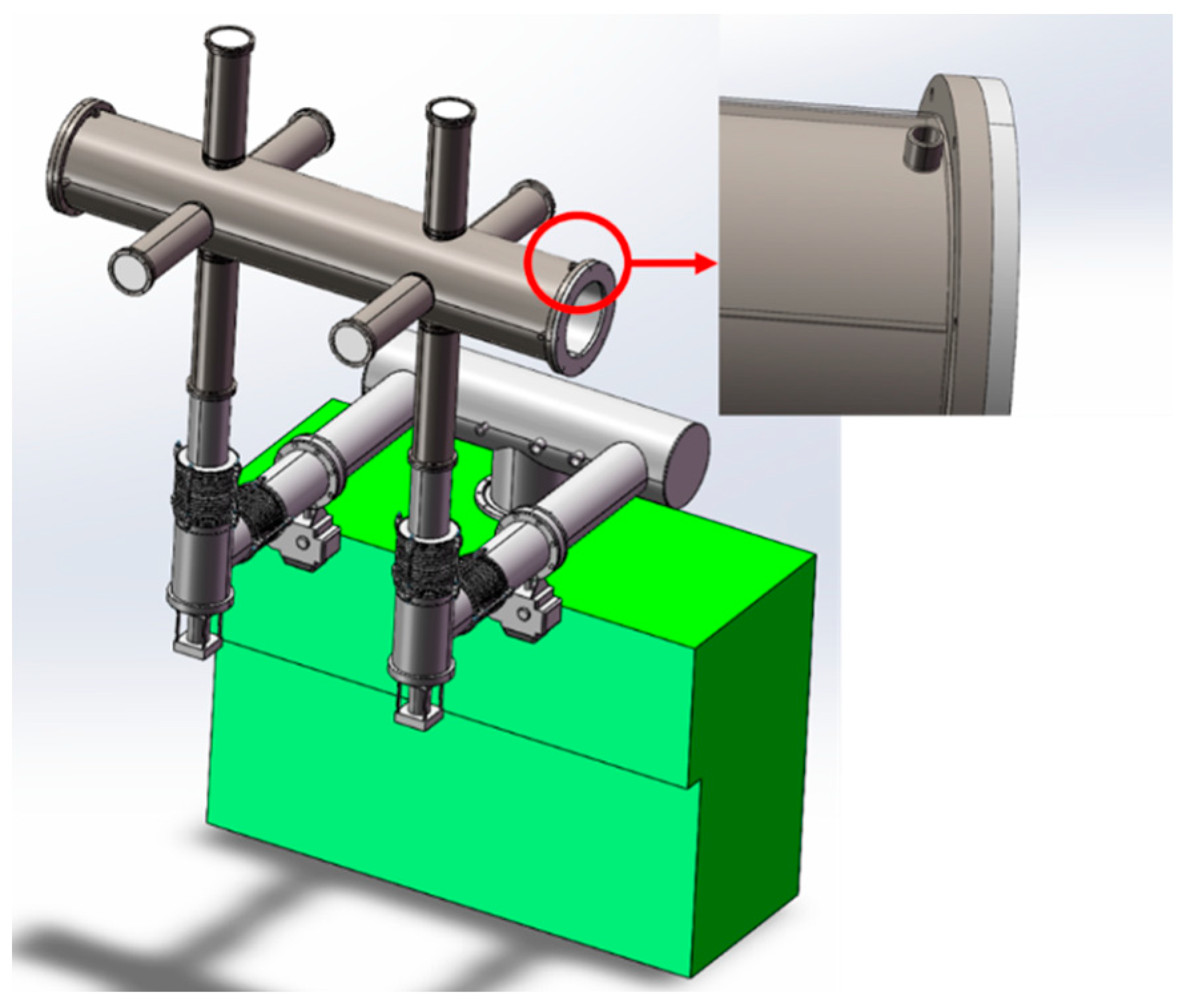
2.4. Vacuum Subsystem

The diagram of the vacuum subsystem is isometrically given in Figure 12. The chamber and associated pipelines for vacuum and diagnosis are strictly constrained by the superconducting magnet. The inner diameter of the vacuum chamber is 350 mm. It features a water-cooled interlayer divided into four independent zones to protect the chamber from plasma bombardment and ensure no heat conduction to the magnet. In addition, 8 pipes are distributed radially with an inner diameter of 150 mm.
Since the cascaded arc plasma source has a low ionization rate, most inlet gas enters the vacuum chamber as neutral particles. As a result, it is desirable to lower the neutral pressure because too much neutral gas may cause inelastic collisions, such as ionization and recombination, which directly reduces heat and particle fluxes of the beam. Therefore, a set of a screw pump of 150 L/s and two Roots pumps of 300 L/s and 2500 L/s is applied. With a 3 L/min argon inflow, the neutral pressure of the chamber can be controlled below 10 Pa. Meanwhile, two butterfly valves with adjustable opening and closing angles are installed to allow flexible adjustment of the pumping rate for the front and back parts of the chamber, respectively.

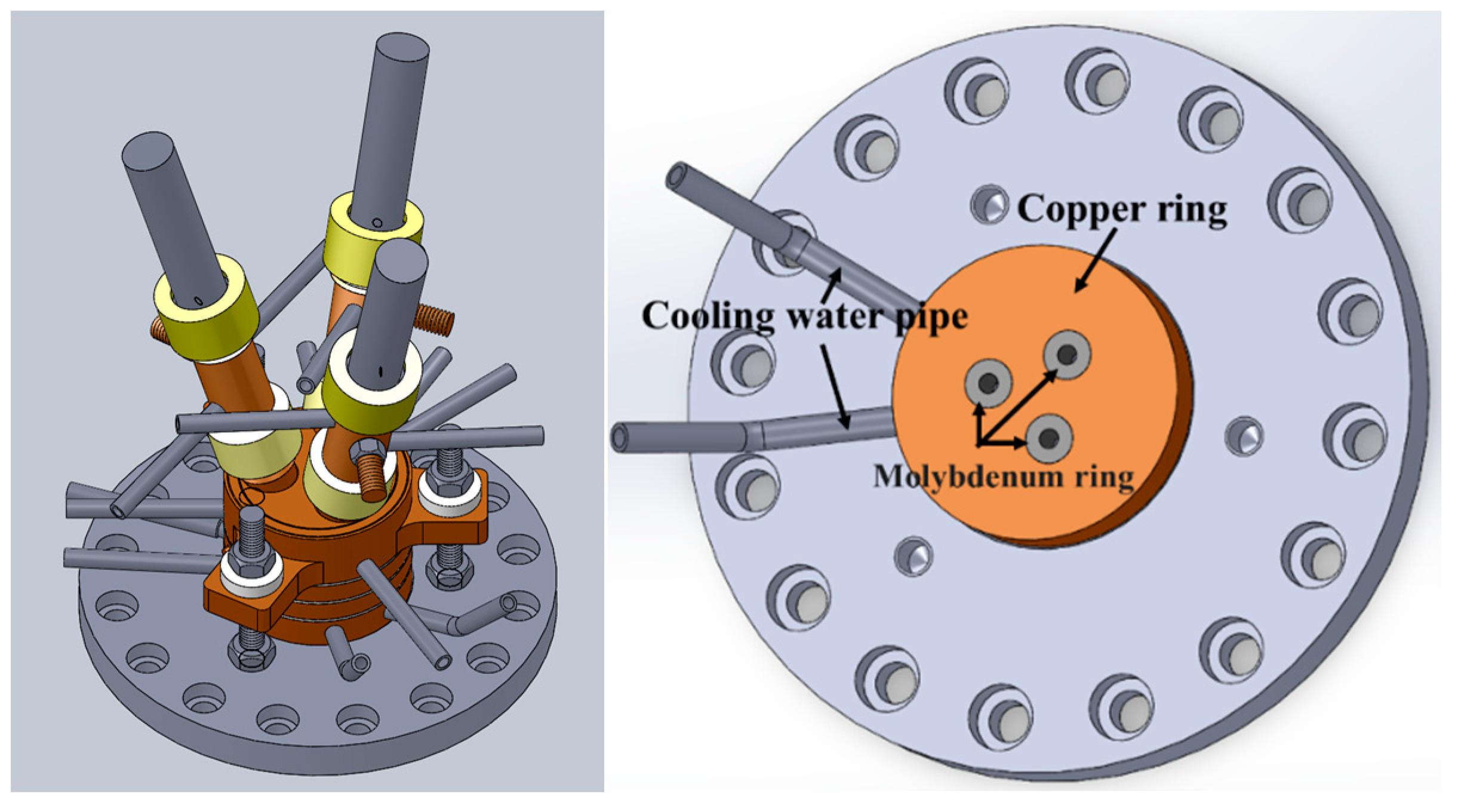
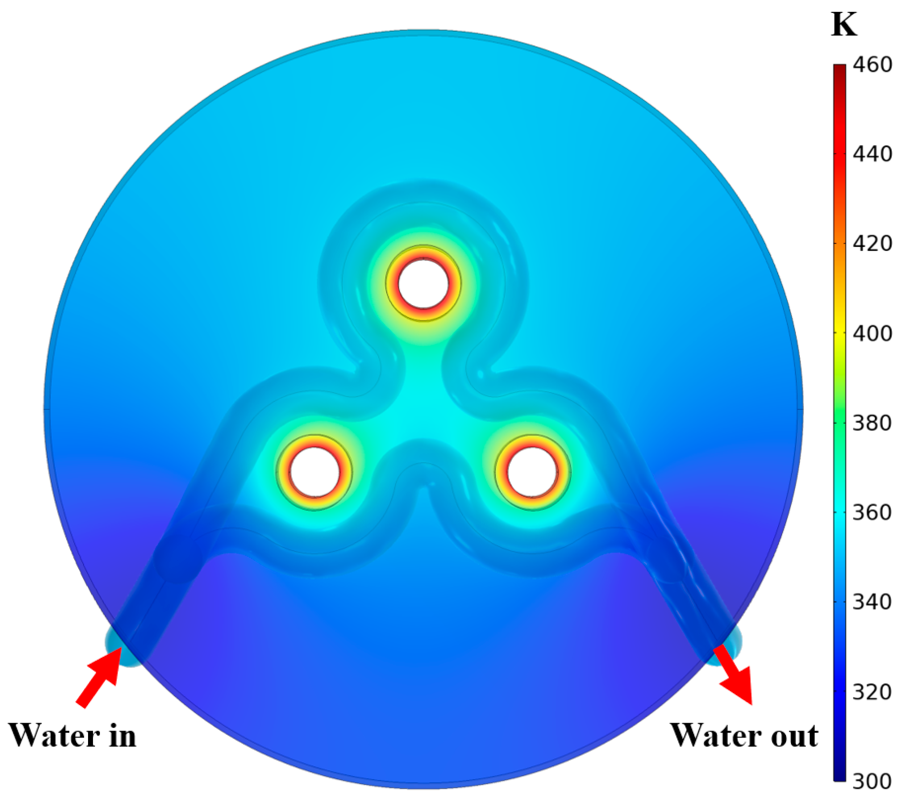
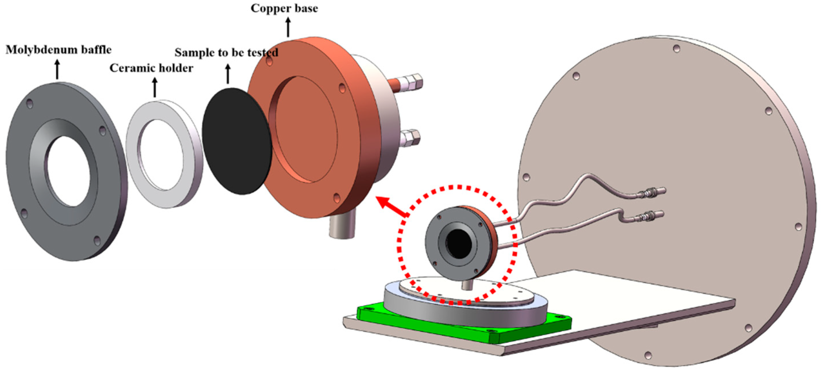
2.5. Target Holder Subsystem

The target subsystem is designed to accomplish the following goals:
  • To be combined with the target probe design for measurements of the heat load flux;
  • To complete tests for different sizes and shapes of materials;
  • To apply proper voltage to the sample for various incident ion energy regulations;
  • To realize plasma-material interaction experiments with different beam incident angles;
  • To achieve effective heat dissipation for long-duration experimental tests;
A schematic diagram of the target holder is shown in Figure 13. The front of the target is a molybdenum baffle attached to a copper cooling plate with ceramic screws. The hole in the center is for the sample exposure or target probe placement. The sample to be analyzed is placed behind the molybdenum baffle. Both the ceramic holder and the molybdenum baffle may be replaced to accommodate the varying sizes and shapes of the samples. These components are mounted on a copper base with water cooling. The copper base is isolated from the rear flange and front molybdenum baffle to allow it to link to a DC power source for bias, along with the sample.
Sensors are installed between the molybdenum baffle and the sample to measure the temperature of the sample. The inlet and outlet water-cooling pipes are also with thermometers and flow meters, and the combination of the two can give the heat load density. The entire target part can be rotated to realize material testing with different incident angles.

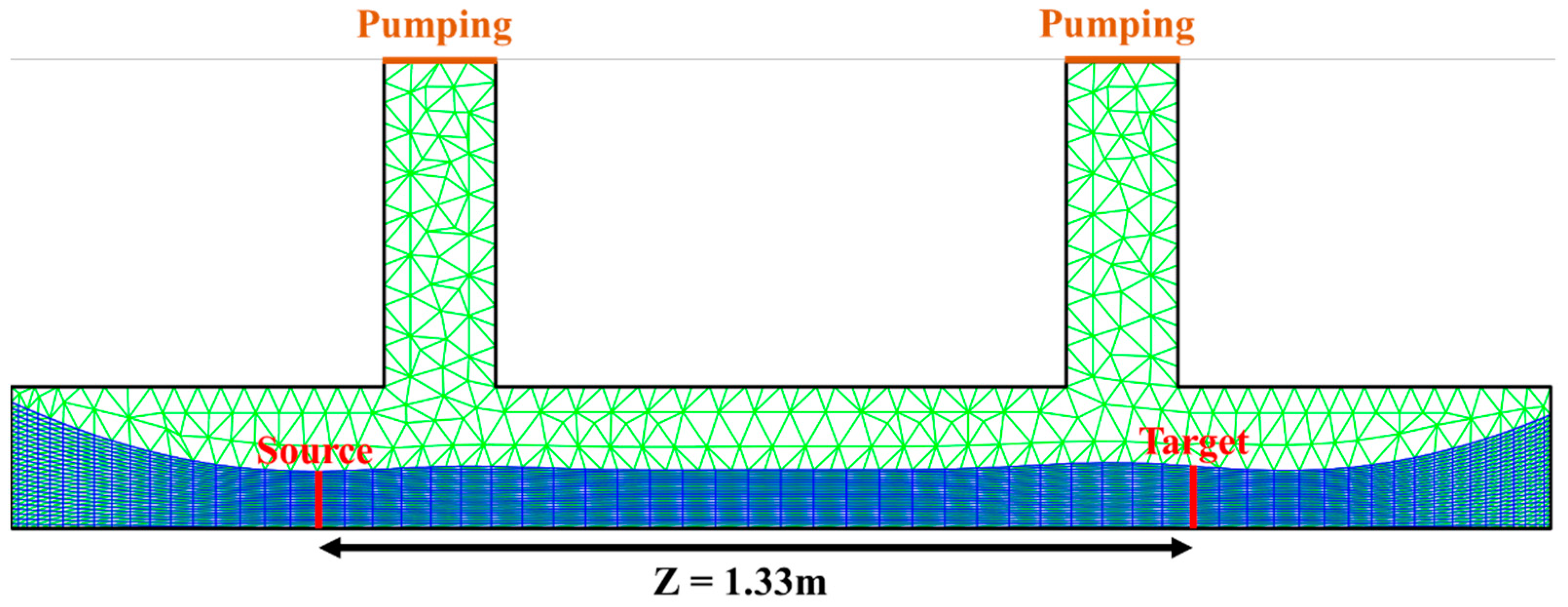
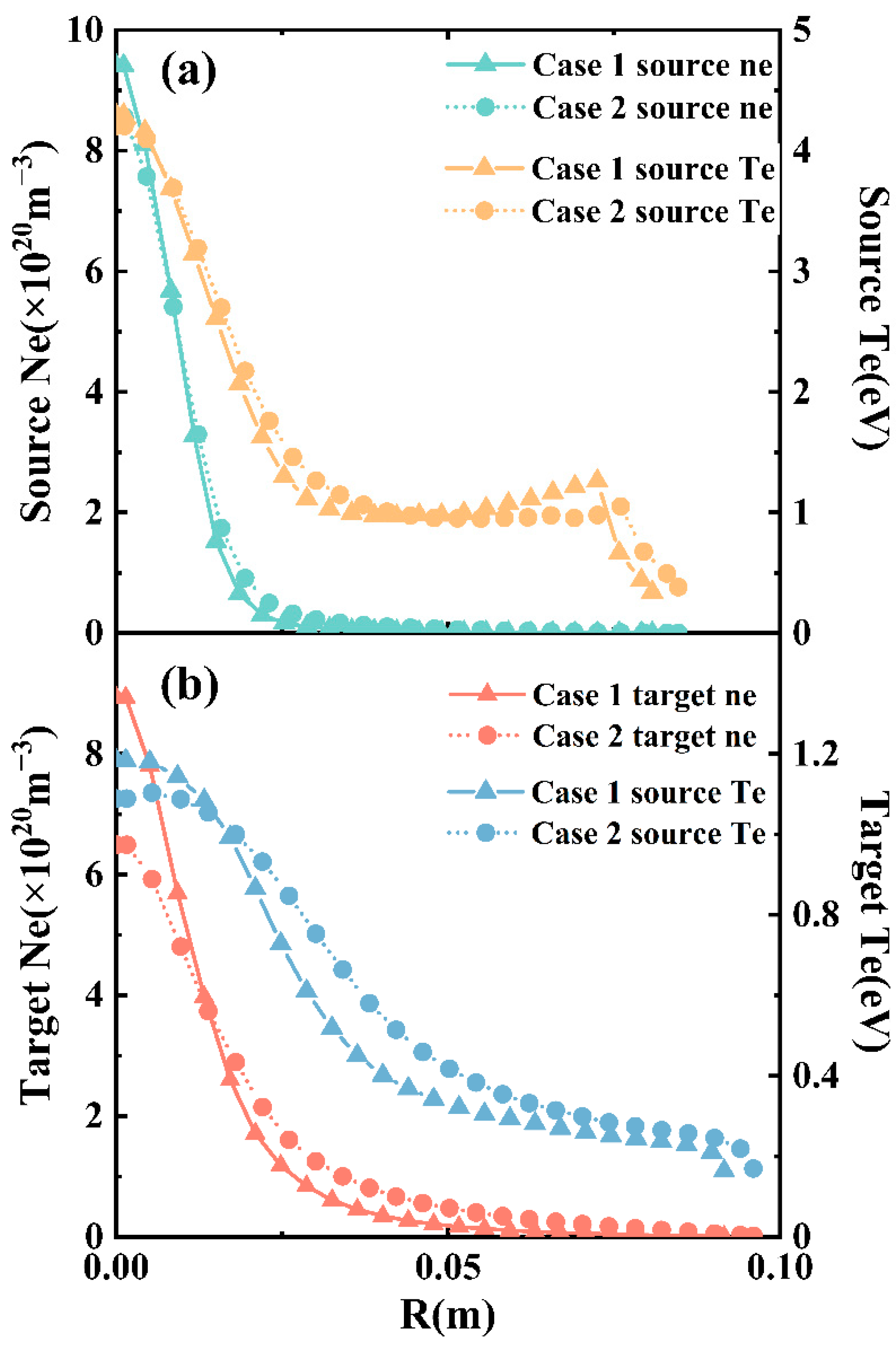
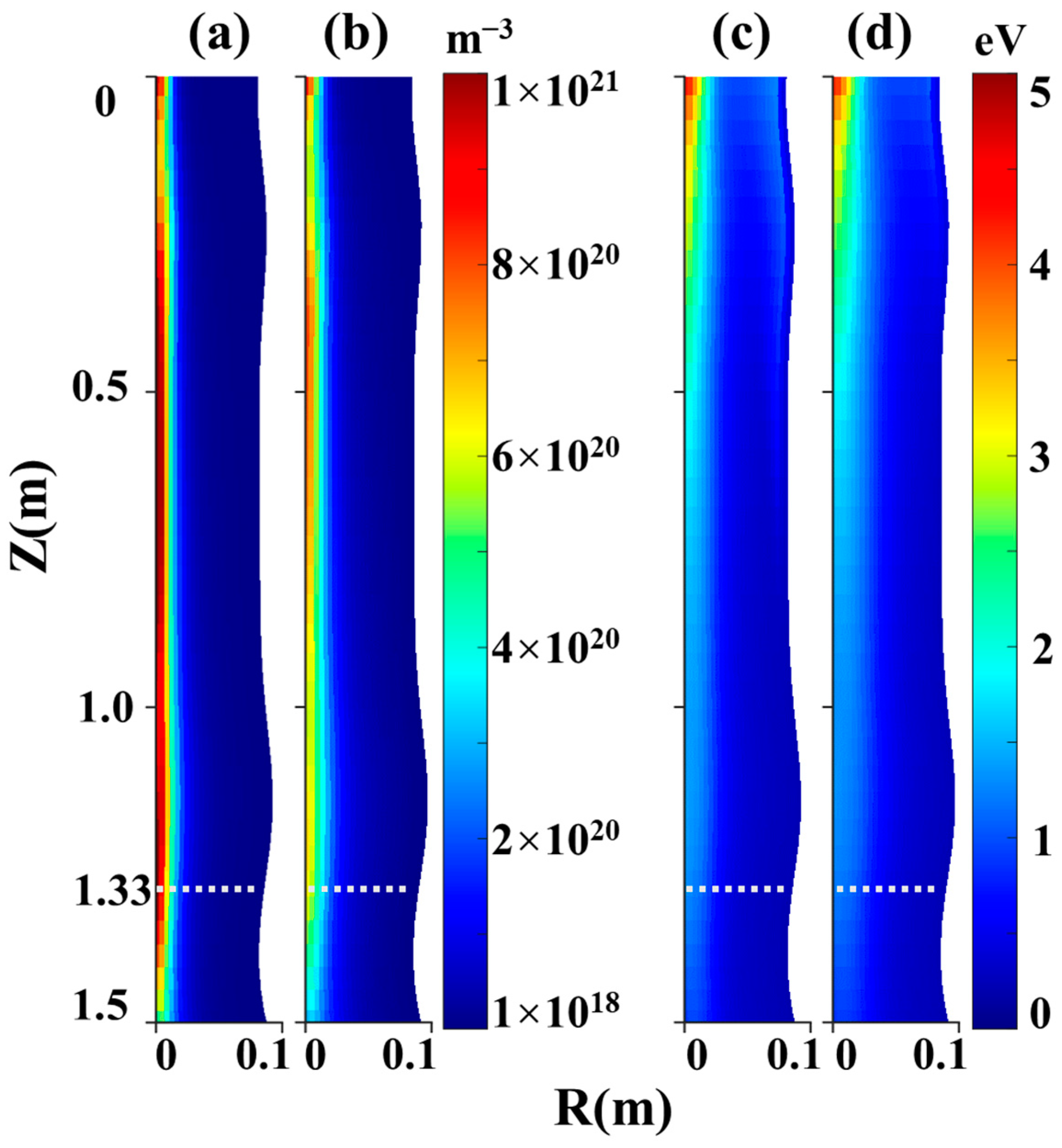
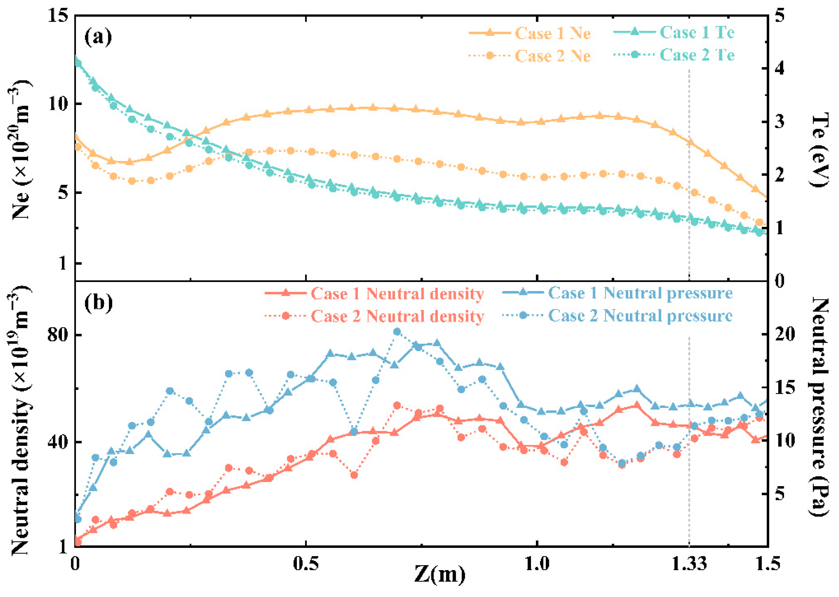
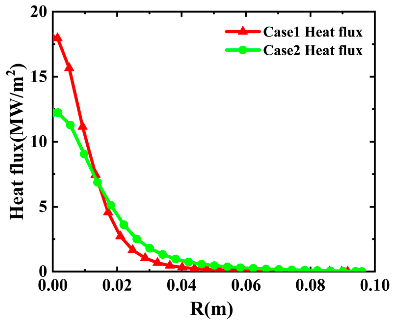
3. Numerical Simulation Device Capability with SOLPS

The capacity of the device is simulated by SOLPS-ITER [30], which has been widely used in linear plasma device simulation [31,32,33,34]. SOLPS-ITER is a code package for tokamak edge plasmas simulations with two main parts, B2.5 for solving multi-fluid simulation with Braginskii equations and EIRENE for neutral particles and molecular ions transport simulation by Monte Carlo methods.
In our simulation, we applied a 2D cylindrical coordinate system (R, Z) with axial symmetry, and the corresponding mesh grid is shown in Figure 14. The lower line is the symmetry axis in a symmetrical boundary condition with zero particle density flux. The quasi-orthogonal mesh region with a high resolution denotes plasma, with grids determined by magnetic field lines axially (in blue). The boundary condition on the outermost line has a decay range of 0.5 cm. The front and rear end in the axial direction are the Bohm boundaries, and energy transmission factors for electrons and ions are 1.0 and 1.5, respectively. The green triangular mesh of a lower resolution is for the EIRENE, where the recycling rate at the two pumping surfaces (bold red lines) is 0.95, and the rest are wall boundaries. There is an open boundary at the target end (assuming Z = 0 at the source, here Z = 1.33 m). The drift effect is ignored, and Braginskii equations are solved only along the direction of the magnetic field. Two sets of anomalous transport coefficients: D = 0.3   m 2 / s , χ e , i = 0.9   m 2 / s (Case 1) and D = 1.0   m 2 / s , χ e , i = 2.0   m 2 / s (Case 2) are adopted, corresponding to strong and weak magnetic fields, respectively. Plasma parameters at the source location are shown in Figure 15a, which are obtained by adjusting the external particle source applied heating power to the source surface (Z = 0). Slight differences in the two cases are due to various grids corresponding to the magnetic fields generated by 275 A and 75 A coil currents.
Figure 15b, Figure 16 and Figure 17 show the simulation results of the two cases. It can be seen that the general features of the two cases are basically the same, with very similar radial distributions of the electron temperature at the target end. The plasma density drops faster after leaving the source surface in Case 2 than that in Case 1, due to the more significant radial diffusion coefficient in a weaker field. In addition, one can find that when Z < 1.1 m, the electron temperature drops from 4 eV to 1 eV, accompanied by a gentle electron density bump. This region is called the ‘recombination front [29]’, where the temperature is between 1 eV to 5 eV, causing ionization to dominate and leading to an electron density increase, but then electron density starts to decrease due to energy relaxation between ions and electrons. When Z > 1.1 m, the electron temperature drops to ~1 eV, and thus recombination is dominant, resulting in a significant electron density drop. In addition, due to the existence of the pumping surface, the neutral particle pressure does not increase obviously along the axial direction.
The heat flux of the plasma beam can be calculated by [20]:
q = 0.5 n e ( 1 + γ ) k T e m [ Υ s h k T e + e E i ]
where T e = T i assumed, Υ is the polytropic exponent (in the adiabatic approximation), m is the ion mass, Υ s h is the sheath heat transmission coefficient, and E i (n eV) is the deuterium ionization potential. Intercepting radial plasma parameters at Z = 1.33 m, the heat flux can be calculated, as shown in Figure 18. It can be observed that more intensive heat flux on the target can be achieved with a stronger magnetic field (Case 1). The major contribution to the heat flux rise comes from the electron density at the target due to the weaker perpendicular transport reduced by the magnetic confinement. Note that though the heat flux calculated provides a reasonable reference, it is numerically simulated by the upstream plasma parameters only without the target boundary setting yet.

4. Summary

The specific design of a new platform, HIT-PSI, at Harbin Institute of Technology for PSI experiments is presented. The device is to simulate the specific plasma environment equivalent to that in divertors of future fusion reactors such as ITER/CFETR and to study plasma–material interactions under high heat and high-density plasma beams, as well as low-temperature plasma processes in the scrape-off layer.
The platform utilizes a five-coil superconducting magnet subsystem with eight room-temperature holes to generate a magnetic field of 2.0 T or beyond to confine high-density plasma of >1020 m−3 generated by a cascaded arc source. All parts of the platform have been processed, and the discharge for the first plasma will be carried out soon. Preliminary simulation results by SOLPS-ITER show that HIT-PSI can reach a heat flux of > 10 MW/m2, capable of experimentally simulating the divertor environment in the future fusion reactor regime.

Author Contributions

Conceptualization, Q.N.; methodology, X.W.; software, M.W. and F.X.; validation, Q.N., F.X., and X.W.; formal analysis, T.H.; investigation, T.H.; resources, Q.N.; writing—original draft preparation, T.H.; writing—review and editing, Q.N.; supervision, X.W. All authors have read and agreed to the published version of the manuscript.

Funding

This work was funded by the National MCF Energy R&D Program of China No. 2018YFE0303105.

Conflicts of Interest

The authors declare no conflict of interest.

References

  1. McCracken, G.M.; Stott, P.E. Plasma-Surface Interactions in Tokamaks. Nucl. Fusion 1979, 19, 889–981. [Google Scholar] [CrossRef]
  2. Linke, J.; Du, J.; Loewenhoff, T.; Pintsuk, G.; Spilker, B.; Steudel, I.; Wirtz, M. Challenges for Plasma-Facing Components in Nuclear Fusion. Matter Radiat. Extrem. 2019, 4, 056201. [Google Scholar] [CrossRef] [Green Version]
  3. Lipschultz, B.; Bonnin, X.; Counsell, G.; Kallenbach, A.; Kukushkin, A.; Krieger, K.; Leonard, A.; Loarte, A.; Neu, R.; Pitts, R.A.; et al. Plasma–Surface Interaction, Scrape-off Layer and Divertor Physics: Implications for ITER. Nucl. Fusion 2007, 47, 1189–1205. [Google Scholar] [CrossRef]
  4. Barabash, V.; Peacock, A.; Fabritsiev, S.; Kalinin, G.; Zinkle, S.; Rowcliffe, A.; Rensman, J.-W.; Tavassoli, A.A.; Marmy, P.; Karditsas, P.J.; et al. Materials Challenges for ITER—Current Status and Future Activities. J. Nucl. Mater. 2007, 367–370, 21–32. [Google Scholar] [CrossRef]
  5. Hirai, T.; Escourbiac, F.; Carpentier-Chouchana, S.; Fedosov, A.; Ferrand, L.; Jokinen, T.; Komarov, V.; Kukushkin, A.; Merola, M.; Mitteau, R.; et al. ITER Tungsten Divertor Design Development and Qualification Program. Fusion Eng. Des. 2013, 88, 1798–1801. [Google Scholar] [CrossRef]
  6. Wan, Y.; Li, J.; Liu, Y.; Wang, X.; Chan, V.; Chen, C.; Duan, X.; Fu, P.; Gao, X.; Feng, K.; et al. Overview of the Present Progress and Activities on the CFETR. Nucl. Fusion 2017, 57, 102009. [Google Scholar] [CrossRef]
  7. Doerner, R.P.; Baldwin, M.J.; Nishijima, D. Plasma-Induced Morphology of Beryllium Targets Exposed in PISCES-B. J. Nucl. Mater. 2014, 455, 1–4. [Google Scholar] [CrossRef]
  8. Roth, J.; Doerner, R.; Baldwin, M.; Dittmar, T.; Xu, H.; Sugiyama, K.; Reinelt, M.; Linsmeier, C.; Oberkofler, M. Oxidation of Beryllium and Exposure of Beryllium Oxide to Deuterium Plasmas in PISCES B. J. Nucl. Mater. 2013, 438, S1044–S1047. [Google Scholar] [CrossRef] [Green Version]
  9. Ohno, N.; Nishijima, D.; Takamura, S.; Uesugi, Y.; Motoyama, M.; Hattori, N.; Arakawa, H.; Ezumi, N.; Krasheninnikov, S.; Pigarov, A.; et al. Static and Dynamic Behaviour of Plasma Detachment in the Divertor Simulator Experiment NAGDIS-II. Nucl. Fusion 2001, 41, 1055. [Google Scholar] [CrossRef]
  10. de Castro, A.; Moynihan, C.; Stemmley, S.; Szott, M.; Ruzic, D.N. Lithium, a Path to Make Fusion Energy Affordable. Phys. Plasmas 2021, 28, 050901. [Google Scholar] [CrossRef]
  11. Ye, Z.-B.; Ma, X.-C.; He, P.-N.; Wang, Z.-J.; Yang, C.; Chen, B.; Chen, J.-J.; Wei, J.-J.; Zhang, K.; Gou, F.-J. Compatibility Investigation of Liquid Tin and Tungsten-Based Capillary Porous System under High-Density Plasma Environment. Tungsten 2020, 2, 94–100. [Google Scholar] [CrossRef]
  12. Shumack, A.E.; Veremiyenko, V.P.; Schram, D.C.; de Blank, H.J.; Goedheer, W.J.; van der Meiden, H.J.; Vijvers, W.A.J.; Westerhout, J.; Lopes Cardozo, N.J.; van Rooij, G.J. Rotation of a Strongly Magnetized Hydrogen Plasma Column Determined from an Asymmetric Balmer- β Spectral Line with Two Radiating Distributions. Phys. Rev. E 2008, 78, 046405. [Google Scholar] [CrossRef] [Green Version]
  13. Biewer, T.M.; Bigelow, T.S.; Caneses, J.F.; Diem, S.J.; Green, D.L.; Kafle, N.; Rapp, J. Proto-MPEX Team Observations of Electron Heating during 28 GHz Microwave Power Application in Proto-MPEX. Phys. Plasmas 2018, 25, 024501. [Google Scholar] [CrossRef]
  14. Kajita, S.; Tsujihara, T.; Aramaki, M.; van der Meiden, H.; Oshima, H.; Ohno, N.; Tanaka, H.; Yasuhara, R.; Akiyama, T.; Fujii, K.; et al. Behavior of 2 3 S Metastable State He Atoms in Low-Temperature Recombining Plasmas. Phys. Plasmas 2017, 24, 073301. [Google Scholar] [CrossRef] [Green Version]
  15. van Eden, G.G.; Reinke, M.L.; Brons, S.; van der Bijl, G.; Krijger, B.; Lavrijsen, R.; Huber, S.P.; Perillo, R.; van de Sanden, M.C.M.; Morgan, T.W. Plasma Radiation Studies in Magnum-PSI Using Resistive Bolometry. Nucl. Fusion 2018, 58, 106006. [Google Scholar] [CrossRef] [Green Version]
  16. van Harskamp, W.E.N.; Brouwer, C.M.; Schram, D.C.; van de Sanden, M.C.M.; Engeln, R. Population Inversion in a Magnetized Hydrogen Plasma Expansion as a Consequence of the Molecular Mutual Neutralization Process. Phys. Rev. E 2011, 83, 036412. [Google Scholar] [CrossRef] [Green Version]
  17. Takano, H.; Ohshima, H.; Kajita, S.; Tanaka, H.; Ohno, N. Development of Thomson Scattering Measurement System for Upstream Plasmas in the NAGDIS-II Device. Plasma Fusion Res. 2019, 14, 2405031. [Google Scholar] [CrossRef] [Green Version]
  18. Rapp, J.; Koppers, W.R.; van Eck, H.J.N.; van Rooij, G.J.; Goedheer, W.J.; de Groot, B.; Al, R.; Graswinckel, M.F.; van den Berg, M.A.; Kruyt, O.; et al. Construction of the Plasma-Wall Experiment Magnum-PSI. Fusion Eng. Des. 2010, 85, 1455–1459. [Google Scholar] [CrossRef]
  19. van de Pol, M.J.; Alonso van der Westen, S.; Aussems, D.U.B.; van den Berg, M.A.; Brons, S.; van Eck, H.J.N.; van Eden, G.G.; Genuit, H.J.W.; van der Meiden, H.J.; Morgan, T.W.; et al. Operational Characteristics of the Superconducting High Flux Plasma Generator Magnum-PSI. Fusion Eng. Des. 2018, 136, 597–601. [Google Scholar] [CrossRef] [Green Version]
  20. Van Eck, H.J.N.; Akkermans, G.R.A.; Alonso van der Westen, S.; Aussems, D.U.B.; van Berkel, M.; Brons, S.; Classen, I.G.J.; van der Meiden, H.J.; Morgan, T.W.; van de Pol, M.J.; et al. High-Fluence and High-Flux Performance Characteristics of the Superconducting Magnum-PSI Linear Plasma Facility. Fusion Eng. Des. 2019, 142, 26–32. [Google Scholar] [CrossRef]
  21. Rapp, J.; Lumsdaine, A.; Beers, C.J.; Biewer, T.M.; Bigelow, T.S.; Caneses, J.F.; Caughman, J.B.O.; Goulding, R.H.; Kafle, N.; Lau, C.H.; et al. Latest Results from Proto-MPEX and the Future Plans for MPEX. Fusion Sci. Technol. 2019, 75, 654–663. [Google Scholar] [CrossRef]
  22. Zhuang, G.; Li, G.Q.; Li, J.; Wan, Y.X.; Liu, Y.; Wang, X.L.; Song, Y.T.; Chan, V.; Yang, Q.W.; Wan, B.N.; et al. Progress of the CFETR Design. Nucl. Fusion 2019, 59, 112010. [Google Scholar] [CrossRef]
  23. Lu, G.-H.; Cheng, L.; Arshad, K.; Yuan, Y.; Wang, J.; Qin, S.; Zhang, Y.; Zhu, K.; Luo, G.-N.; Zhou, H.; et al. Development and Optimization of STEP—A Linear Plasma Device for Plasma-Material Interaction Studies. Fusion Sci. Technol. 2017, 71, 177–186. [Google Scholar] [CrossRef]
  24. Ikeda, K. Progress in the ITER Physics Basis. Nucl. Fusion 2007, 47, E01. [Google Scholar] [CrossRef]
  25. Pitts, R.A.; Carpentier, S.; Escourbiac, F.; Hirai, T.; Komarov, V.; Kukushkin, A.S.; Lisgo, S.; Loarte, A.; Merola, M.; Mitteau, R.; et al. Physics Basis and Design of the ITER Plasma-Facing Components. J. Nucl. Mater. 2011, 415, S957–S964. [Google Scholar] [CrossRef]
  26. Vijvers, W.A.J.; de Groot, B.; Al, R.S.; van den Berg, M.A.; van Eck, H.J.N.; Goedheer, W.J.; Kleyn, A.W.; Koppers, W.R.; Kruijt, O.G.; Lopes Cardozo, N.J.; et al. Multiple Discharge Channels in a Cascaded Arc to Produce Large Diameter Plasma Beams. Fusion Eng. Des. 2009, 84, 1933–1936. [Google Scholar] [CrossRef]
  27. Xu, G.-Y. Studies of the Characteristics on Cascade Arc Plasma Sources. Master’s Thesis, Harbin Institute of Technology, Harbin, China, 2020. [Google Scholar] [CrossRef]
  28. De Temmerman, G.; van den Berg, M.A.; Scholten, J.; Lof, A.; van der Meiden, H.J.; van Eck, H.J.N.; Morgan, T.W.; de Kruijf, T.M.; Zeijlmans van Emmichoven, P.A.; Zielinski, J.J. High Heat Flux Capabilities of the Magnum-PSI Linear Plasma Device. Fusion Eng. Des. 2013, 88, 483–487. [Google Scholar] [CrossRef] [Green Version]
  29. International Commission on Non-Ionizing Radiation Protection. Guidelines on Limits of Exposure to Static Magnetic Fields. Health Phys. 2009, 96, 504–514. [Google Scholar] [CrossRef]
  30. Schneider, R.; Bonnin, X.; Borrass, K.; Coster, D.P.; Kastelewicz, H.; Reiter, D.; Rozhansky, V.A.; Braams, B.J. Plasma Edge Physics with B2-Eirene. Contrib. Plasma Phys. 2006, 46, 3–191. [Google Scholar] [CrossRef]
  31. Baeva, M.; Goedheer, W.J.; Lopes Cardozo, N.J.; Reiter, D. B2-EIRENE Simulation of Plasma and Neutrals in MAGNUM-PSI. J. Nucl. Mater. 2007, 363–365, 330–334. [Google Scholar] [CrossRef]
  32. Rapp, J.; Owen, L.W.; Bonnin, X.; Caneses, J.F.; Canik, J.M.; Corr, C.; Lore, J.D. Transport Simulations of Linear Plasma Generators with the B2.5-Eirene and EMC3-Eirene Codes. J. Nucl. Mater. 2015, 463, 510–514. [Google Scholar] [CrossRef]
  33. Owen, L.W.; Caneses, J.F.; Canik, J.; Lore, J.D.; Corr, C.; Blackwell, B.; Bonnin, X.; Rapp, J. B2.5-Eirene Modeling of Radial Transport in the MAGPIE Linear Plasma Device. Plasma Sources Sci. Technol. 2017, 26, 055005. [Google Scholar] [CrossRef]
  34. Sala, M.; Tonello, E.; Uccello, A.; Bonnin, X.; Ricci, D.; Dellasega, D.; Granucci, G.; Passoni, M. Simulations of Argon Plasmas in the Linear Plasma Device GyM with the SOLPS-ITER Code. Plasma Phys. Control. Fusion 2020, 62, 055005. [Google Scholar] [CrossRef]
Figure 1. The conceptual drawing (left) and schematic design (right) of HIT-PSI.
Applsci 12 10501 g001
Figure 2. Schematic drawing of a three-channel cascaded arc plasma source and its anode flange for HIT-PSI.
Applsci 12 10501 g002
Figure 3. Temperature simulation result of an optimal design for the cooling waterway of cascade plates.
Applsci 12 10501 g003
Figure 4. The design plan of the superconducting magnet subsystem, with superconducting coils (a) wrapped with two layers of Dewar (b,c) and a layer of thermal insulation cold shield (e), and the magnets wrapped with magnetic shielding iron shield (f) with eight radially distributed room temperature ports (d), as well as a service tower (g) on the top.
Applsci 12 10501 g004
Figure 5. Sketch of superconducting magnet dimensions without external magnetic shielding.
Applsci 12 10501 g005
Figure 6. The calculated 2D magnetic field distribution. The main transmission region of the plasma beam is surrounded by red dots, with an axial length of 1300 mm and a radial radius of 50 mm. Magnetic field lines are almost flat in this region.
Applsci 12 10501 g006
Figure 7. The calculated magnetic field strength on the axis with an average of 2.31 T in the main plasma transmission region.
Applsci 12 10501 g007
Figure 8. Axial (left) and radial (right) Lorentz force distributions of the coils.
Applsci 12 10501 g008
Figure 9. Quench protection circuit diagram.
Applsci 12 10501 g009
Figure 10. Schematic diagram of the current variation measured in a quench test. The working current in the quench test was 175 A, and it took about 6 s for the current to decay.
Applsci 12 10501 g010
Figure 11. Distribution of the stray magnetic field within 3 m radius from the magnet, with 100 Gausses of the stray field at 1.9 m and 50 Gausses of the stray field at 2.3 m.
Applsci 12 10501 g011
Figure 12. Schematic drawing of the vacuum subsystem. The main vacuum chamber has a water-cooled interlayer.
Applsci 12 10501 g012
Figure 13. Schematic drawing of the rotatable angle target system and the facing plasma part.
Applsci 12 10501 g013
Figure 14. The simulation mesh grid distribution. The source and target positions are selected with a distance of 1.33 m.
Applsci 12 10501 g014
Figure 15. The electron density/temperature radial distributions at the source (a) and target (b) locations in the two cases.
Applsci 12 10501 g015
Figure 16. Simulation results of 2D distributions of electron density of Case 1 (a) and Case 2 (b), and electron temperature of Case 1 (c) and Case 2 (d). The source position in Figure 14 corresponds to Z = 0.
Applsci 12 10501 g016
Figure 17. The axial distributions of plasma (a) and neutral parameters (b) in the two cases. The target position parameters are taken from those in Z = 1.33 m.
Applsci 12 10501 g017
Figure 18. Radial heat flux distribution calculated by plasma parameters at Z = 1.33 m.
Applsci 12 10501 g018
Table 1. Parameters of ITER required and existing/designed devices.
FacilitySourceTe
(eV)
Ne
(m−3)
Particle Flux
(m−2s−1)
B (T)Heat Flux (MW/m2)Ref.
PISCES-BRF~2010191022–10230.2-[7,8]
NAGDIS-IIRF~2010191022–10230.4-[9]
STEPLaB6~2010191022–10230.4-[23]
Magnum -PSICascaded arc<10≥1021>10242.5>10[20]
MPEXRF~4010191022–10235.0>10[21]
HIT-PSI (designed)Cascaded arc<5≥1021>10242.0>10
ITER Divertor-1–101021>10245.0>10[24]
Table 2. Parameters of superconducting magnet subsystem.
ParameterValue
Number of coils5
Outer diameter956 mm
Inner diameter450 mm
Axial length1804.4 mm
Maximum operating current275 A
Mean strength of the axial magnetic field >2.0 T
Magnetic inductance35.66 H
Total stored energy1.348 MJ
Table 3. Coil Parameters of superconducting magnet subsystem.
ParameterCoils-1/5Coil-3Coils-2/4
Rin (mm)274.3274.3274.3
Rout (mm)315.5286.7297.0
Z (cm)150463.2100
Turns360033121320
Layers401222
Bmax (T)5.022.473.25
Critical current (A)651.5>900>900
Table 4. Inductance matrix of the five coils.
Coil 1Coil 2Coil 3Coil 4Coil 5
Coil 19.56
Coil 20.441.47
Coil 30.370.764.61
Coil 40.050.060.761.47
Coil 50.060.050.370.449.56
Publisher’s Note: MDPI stays neutral with regard to jurisdictional claims in published maps and institutional affiliations.

