Article

Investigating the Obstacle Climbing Ability of a Coal Mine Search-and-Rescue Robot with a Hydraulic Mechanism

College of General Aviation and Flight, Nanjing University of Aeronautics and Astronautics, Nanjing 210016, China
*
Author to whom correspondence should be addressed.
Appl. Sci. 2022, 12(20), 10485; https://doi.org/10.3390/app122010485
Submission received: 24 August 2022 / Revised: 16 September 2022 / Accepted: 11 October 2022 / Published: 18 October 2022
(This article belongs to the Section Mechanical Engineering)

Abstract

:
Due to the perilous conditions in coal mine accidents, trapped people need to be rescued as soon as possible. The danger and complexity of this environment have brought great difficulties for search and rescue. The emergence of rescue robots has addressed this problem, and the improvement of their search-and-rescue ability is a key concern for rescue robot designers. Based on previous experience of a tracked mobile robot, this paper proposes a new solution via the addition of adjustive rocker arms. For this purpose, a hydraulic unit is installed between the rocker arms and the robot, which enables the rocker arms to be pulled back and forth, enabling its adaptation to more complex environments. In addition, based on kinematics equations, by analyzing the motion rules and characteristics of climbing typical obstacles including stairs, grooves, and lug steps, the present research not only works out the centroid coordinates but also explores the maximal obstacle height. The results show that when the rocker arms are extended by hydraulic pressure, the obstacle-climbing height of the robot increases 16.7 percent. This demonstrates the improvement in obstacle climbing ability and rescue efficiency in complex environments.

1. Introduction

Robots were originally mainly used in industrial production such as for automobiles and household appliances. Germany, Japan, and other countries have actively developed industrial robot technology, which brings them higher efficiency, lower labor force requirements, and a strong economy. In the 21st century, robotics has thrived in the rapid development of computers and control technology. Moreover, with the advancement of society, robots are not merely used to serve industrial production but also to handle more complex and diverse tasks. Therefore, with the advantage of strong adaptation to the environment, more and more mobile robots have been used in disaster relief, dangerous goods transportation, and other dangerous or difficult operations.
In the 1980s, researchers proposed the application of mobile robots in disaster relief. However, such mobile robots were not invented until 1995. In 2001, rescue robots were used in the United States’ “9/11” incident, attracting the attention of many researchers. Although the robots had performed well in this rescue operation, there were also many problems, such as instability, inferior waterproofing, limited vision, and so on [1]. After this incident, the scientific research institutions in the United States paid more attention to rescue robot research. Of these, iRobot’s Packbot and the Warrior series of tracked rescue robots have been well used [2]. For example, the latter can be operated remotely; it is about 90 cm long, 80 cm wide, and 53 cm high and its total mass is 250 kg. Equipped with a mechanical arm, it can enter areas that are difficult to reach for human beings. In addition, unmanned aerial robots are also widely used in disaster relief. In addition to the military and commercial applications of drones, they are efficient in supporting emergency management [3]. The cameras and sensors carried by drones can also facilitate access to the environmental map of the disaster relief site, which can provide assistance in large area rescues [4]. The robots can adapt to the rescue site environment and can enable communication with the trapped casualties in real time, greatly improving the safety of personnel and the efficiency of rescue. This reduces casualties and secondary damage in the disaster area [5,6].
Though the research and development of mobile robots started relatively late in China, more and more universities and scientific research institutions have started to pay attention to this area. In recent years, China’s research on mobile robots has also achieved some notable results. For example, in 2006, the China University of Mining and Technology developed a mobile robot, CUMT-1, for coal mine rescues. The robot, equipped with a camera, temperature sensor, gas sensor, and real-time voice communication system, could realize real-time monitoring for underground environments [7]. In 2008, Xidian University developed a six-track mobile robot with front and rear rocker arms [8]. The double rocker arms provided the mobile robot with a better obstacle-crossing ability, making it better suited for complex terrain. The University of Science and Technology of China developed a wheel-legged hybrid mobile robot called HyTR-I [9,10]. The wheels and legs of the robot are independent, and its wheeled motion mechanism can work alone on flat ground allowing it to move quickly. The Harbin Institute of Technology also developed a wheel-legged hybrid mobile robot called HIT-HYBTOR [11,12,13]. The wheels are installed at the ends of the legs, and the wheels at each end are independently driven.
In recent years, clean energy such as photovoltaic power generation, wind power generation, and hydropower generation have developed rapidly. However, due to site and cost constraints, these clean energy sources have not been widely adopted. Therefore, the world is currently dominated by thermal power generation. In 2016, China’s thermal power generation was 4,288.6 billion kWh, of which coal-fired power generation accounted for 91.1% [14]. Therefore, in the near future, the demand for coal in China and even the world will still be very large, and coal production is still needed.
Most coal production is carried out underground. Due to the harsh underground working environment, confined space, and complex structure, coal mine accidents occur from time to time. In real rescue situations, the probability of survival of the wounded trapped in rubble after more than 48 h will decrease [15]. After a coal mine accident, in order to be able to rescue the wounded during the critical period of rescue, it is necessary to have search-and-rescue robots that can replace or partially replace manual rescue. The main types of search-and-rescue robot are wheel type [16,17,18], leg type [19], crawler type, and the snake structure [20,21]. Of these, the wheel type is simple and the transmission rate is high, but its ability to climb over steps and other obstacles is poor. The leg type is highly adaptable, but the speed of movement is slow, and the operation is difficult. The snake structure is based on the bionic principle, and its stability is good, but too many joints increase the difficulty of modeling and manipulation of the robot. The crawler structure has a large support area, a small turning radius, and good maneuverability. The grousers attached to the track can increase friction and output greater traction [22]. Mobile rescue robots also include compound walking robots [23,24] and bio-robots [25,26].
The above analysis shows that more and more robots are being used in the post-disaster relief process. Crawler type search-and-rescue robots have been widely used in various environments due to their good adaptability to the terrain. However, there are problems such as their weak adaptability to the environment and poor stability in climbing obstacles. If these problems occur in real-world situations, this will seriously restrict the efficiency of disaster rescue.
In order to address these problems of tracked robots, a new tracked rescue robot is designed in this paper. The main crawler and the front swing arm of the underground search-and-rescue robot can be equipped with a hydraulic mechanism [27], so that the swing arm has a certain degree of flexibility. In this way, the position of the center of gravity can be changed flexibly, enabling it to cross wider grooves and steps, improving the robot’s ability to climb obstacles. At the same time, the main crawler and the rocker arm are driven by separate motors to enhance its driving capability.

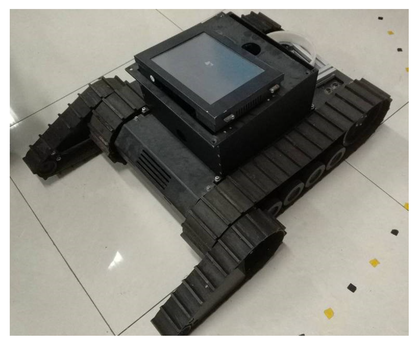
2. Structure Design of the Search-and-Rescue Robot

2.1. Robot Design Scheme

The rocker arm and the main body of the conventional tracked search-and-rescue robot are interconnected, the rocker arm cannot be extended, and the robot’s ability to cross obstacles is fixed. The structure of an existing tracked search-and-rescue robot is shown in Figure 1.
The whole design scheme of the search-and-rescue robot proposed in this paper is shown in Figure 2.

2.2. Hydraulic Mechanism Analysis

The structure of the search-and-rescue robot was drawn using SolidWorks software to obtain a design sketch. This design scheme refers to the work in [27], installing a hydraulic mechanism between the rocker arm and the main body of the robot (part 3 in Figure 2). The working principle is that the hydraulic cylinder in mechanism 3 converts hydraulic energy into mechanical energy to perform a linear reciprocating motion. The flexibility of the hydraulic mechanism allows the robot’s rocker arm to extend back and forth, thereby improving the robot’s ability to climb over obstacles such as steps.

2.3. Simplified Model of the Search-and-Rescue Robot

A simplified model of the search-and-rescue robot with two poses is shown in Figure 3.
The definitions of the letters in Figure 3 are shown in Table 1.
Figure 3 shows the simplified structure of the search-and-rescue robot. The coordinate system was established for the robot through RPY transformation [28]. X0OY0 is the fixed coordinate system of the crawler wheel at the rear of the robot body, that is, the global coordinate system. X1OY1 is the main transformed coordinate system, while X2OY2 is the coordinate system of the rocker arm. The counterclockwise rotation direction was set as the positive direction.

3. Obtaining the Solution of Centroid Coordinates

3.1. Transformation between the Body Coordinate System and Global Coordinate System

The coordinate system X1OY1 is rotated relative to the coordinate system X0OY0, i.e., it is rotated δ, θ, and η degrees around the X-, Y-, and Z-axes, respectively. Then the RPY equivalent rotation matrix R z y x 1 0 ( η , θ , δ ) can be obtained. Because the rotation in each direction is around the corresponding axis of the reference coordinate system, we can obtain [28]:
R z y x 1 0 ( η , θ , δ ) = R z ( η ) R y ( θ ) R x ( δ )
where
R x ( δ ) = [ 1 0 0 0 c δ s δ 0 s δ c δ ] , R y ( θ ) = [ c θ 0 s θ 0 1 0 s θ 0 c θ ] , R z ( η ) = [ c η s η 0 s η c η 0 0 0 1 ]
In the above equation, sin and cos are represented by s and c, respectively. Substituting into Equation (1), one can obtain:
R z y x 1 0 ( η , θ , δ ) = [ c η c θ c η s θ s δ s η c δ c η s δ c θ + s η s δ s η c θ s η s θ s δ + c η c δ s η s θ c δ c η s δ s θ c θ s δ c θ c δ ]
The transformation matrix of the body coordinate system X1OY1 relative to the fixed coordinate system X1OY1 can then be obtained:
T 1 0 = R z y x 1 0 ( η , θ , δ ) T r a n s ( P x , P y , P z ) = [ c η c θ c η s θ s δ s η c δ c η s θ c δ + s η s δ P x s η s θ s η s θ s δ + c η c δ s η s θ c δ c η s δ P y s θ c θ s δ c θ c δ P z 0 0 0 1 ]
where Trans(Px, Py, Pz) is the translational transformation matrix, and Px, Py, and Pz are the translation vectors of each coordinate axis, respectively.
When the robot actually climbs the steps, the robot only rotates around the Z-axis. Therefore, θ = 0, δ = 0, and Pz = 0. Substituting these into the above equation, one can obtain:
T 1 0 = [ c η s η 0 I 2 s η c η 0 0 0 0 1 0 0 0 0 1 ]

3.2. Transformation between the Centroid Coordinate System and Body Coordinate System
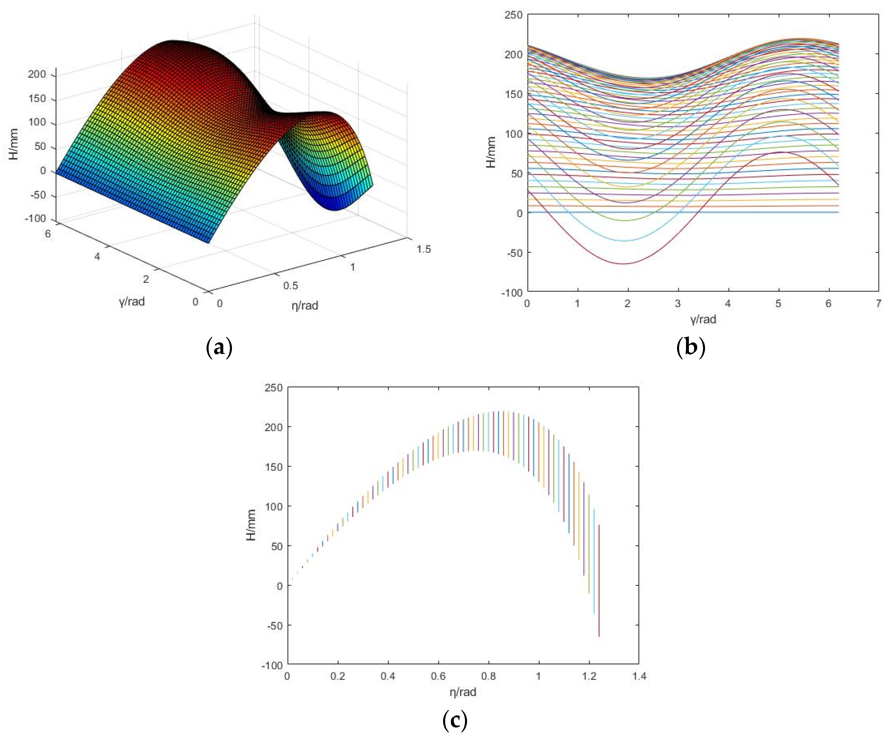
The translation transformation matrix of the robot rocker arm coordinate system relative to the main body coordinate system is as follows:
T 2 1 = T r a n s = ( x , L 1 L 2 ) R z ( θ )
The homogeneous matrix of the mass center of the robot body and the rocker arm in its own coordinate system is as follows:
P 1 1 = ( 0 h 2 0 1 ) T P 2 2 = ( L 4 0 0 1 ) T
From the literature [28], the centroid matrix from the robot coordinate system to the fixed coordinate system can be obtained:
P 0 = T 1 1 0 P = [ [ ( G 2 c θ L 4 + G 2 L 1 G 2 L 2 ) c η G 1 h 2 s η G 2 s θ L 4 s η + ( G 1 + G 2 ) L 2 ] G 1 + G 2 ( G 2 c θ L 4 s η + G 1 h 2 c η + G 2 s θ L 4 c η ) G 1 + G 2 0 1 ]
where L2 is the distance from the mass center of the robot to the coordinate system X0OY0.
When the rocker arm is fully extended, the simplified model of the robot is as shown in Figure 3b. From the figure, we can see that the entire robot is stretched at this time. This is mainly reflected in the distance between the coordinate system X0OY0 and the coordinate system X1OY1, which changes from L1 to L11. If other data remain unchanged, the related transformation matrix will also change accordingly.
Similarly, the mass center matrix of the robot in the fixed coordinate system is:
P 0 = T 1 1 0 P = [ [ ( G 2 c θ L 4 + G 2 L 11 G 2 L 2 ) c η G 1 h 2 s η G 2 s θ L 4 s η + ( G 1 + G 2 ) L 2 ] G 1 + G 2 ( G 2 c θ L 4 s η + G 1 h 2 c η + G 2 s θ L 4 c η ) G 1 + G 2 0 1 ]

4. Analysis

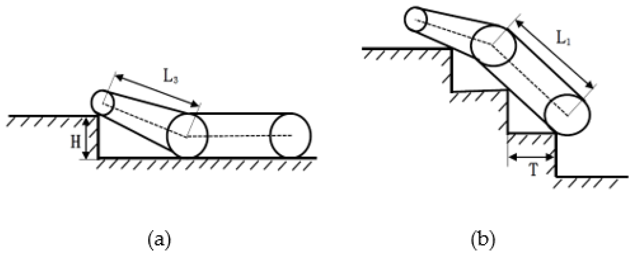
4.1. Analysis of the Rocker Arm in a Retracted State during Step Crossing

By determining the relationship between the center of mass and the angle of rotation, the theoretical height for the robot climbing the step can be analyzed [29].
Considering Figure 4d, it can be concluded that the robot can climb the step smoothly only when the center of gravity is higher than the edge of the step. Therefore, further analysis of this part was performed to establish a coordinate system with the axis of the rear crawler wheel of the robot as the coordinate origin.
The mathematical model of the climbable obstacle height of the robot can be obtained from the geometric relationship of Figure 5:
H = R + X G sin η + Y G cos η Y G + R cos μ
where R is the radius of the large wheel of the robot, H is the height of the step, XG is the coordinate of the mass center on the X-axis, and YG is the coordinate of the mass center on the Y-axis.
It can be seen from Figure 4a that η = 0 at this time. Combined with Equation (7), the coordinate formula of robot centroid can be obtained:
X G = G 1 L 2 + G 2 L 1 G 1 + G 2 + G 2 L 4 G 1 + G 2 cos γ Y G = G 1 h 2 G 1 + G 2 + G 2 L 4 G 1 + G 2 sin γ
where γ is the swing angle of the rocker arm, and η is the pitch angle of the robot. The design parameters of the robot are: G = 38 kg; m1 = 30 kg; m2 = 8 kg; L1 = 510 mm; L2 = 255 mm; L3 = 300 mm; L4 = 115 mm; h2 = 70 mm; R = 100 mm; r = 30 mm.
To determine the relationship between the height H of the step and the angle γ, η, first, the first and second derivatives of γ and η in Equation (9) must be determined. When the robot climbs the step, γ is in the range (0, 2π), and η is in the range (0, π/2). Therefore, when the first-order derivative is zero and the second-order derivative is less than zero, H is the largest. That is, when the rocker arm is horizontal (η + γ = 2π), the robot reaches the maximum height Hmax of climbing the step. Finally, the parameters of the robot are substituted into Equations (9) and (10). The mathematical model related to H is solved using the simulation software optimization toolbox and is simulated to obtain the relationship between the height H of the robot across the step and the swing angle γ of the rocker arm, as well as the pitch angle η of the robot body.
In Figure 6, γ is the rocker arm swing angle, and η is the pitch angle. From the simulation results, one can learn that when γ = 5.4605 rad and η = 0.8227 rad, the maximum height when the robot climbs the step is Hmax = 187.74 mm. That is, η + γ = 6.2832 ≈ 2π.
When the robot crosses the barrier, it first needs the rocker arm to be able to touch the end of the step, and then the rocker arm and the main body need to be in a straight line during the crossing process. The robot’s center of gravity should exceed the contact point between the robot and the step so that the crossing can be carried out smoothly. It can be seen from the figure that when the pitch angle is 0, the swing angle of the rocker arm has no effect on the obstacle height of the robot; when the swing angle of the rocker arm is 0, a change of the pitch angle will result in a change of the obstacle height of the robot. This shows that the pitch angle has a greater influence on the robot’s obstacle height, which is consistent with the robot’s obstacle clearance. This also shows that the above analysis is correct.

4.2. Analysis of the Rocker Arm in an Extended State during Step Crossing

Figure 7 is a simplified diagram of the robot climbing a step when the rocker arm is extended. At this point, the robot rocker arm is fully extended, the overall size of the robot becomes longer, and the center of mass also moves forward.
Figure 8 shows the robot at the critical point of climbing—at this point, the center of gravity of the robot and the con-tact point are on the same vertical line.
It can be seen from Figure 3b that when the rocker arm extends, the distance between the coordinate system X0OY0 and the coordinate system X2OY2 changes from L1 to L11. At this point, L11 = 710 mm.
If the other relevant data of the robot remains unchanged, Figure 9 is obtained by MATLAB simulation:
According to the simulation results, when γ = 5.4320 rad and η = 0.8512 rad, the maximum height for the robot climbing the step is Hmax = 219.01 mm. At this point, η + γ = 6.2832 ≈ 2π, which is still consistent with the analysis. When the rocker arm is extended, the maximum height for the robot climbing the step is increased by 16.7%. It can also be seen from Figure 9 that whether the rocker arm is extended or retracted, the obstacle height of the robot will vary according to the swing angle and pitch angle of the rocker arm. It can be seen that when the hydraulic mechanism is added, the obstacle-climbing ability of the search-and-rescue robot is improved to a certain extent, improving its rescue efficiency when the rescue is underground.

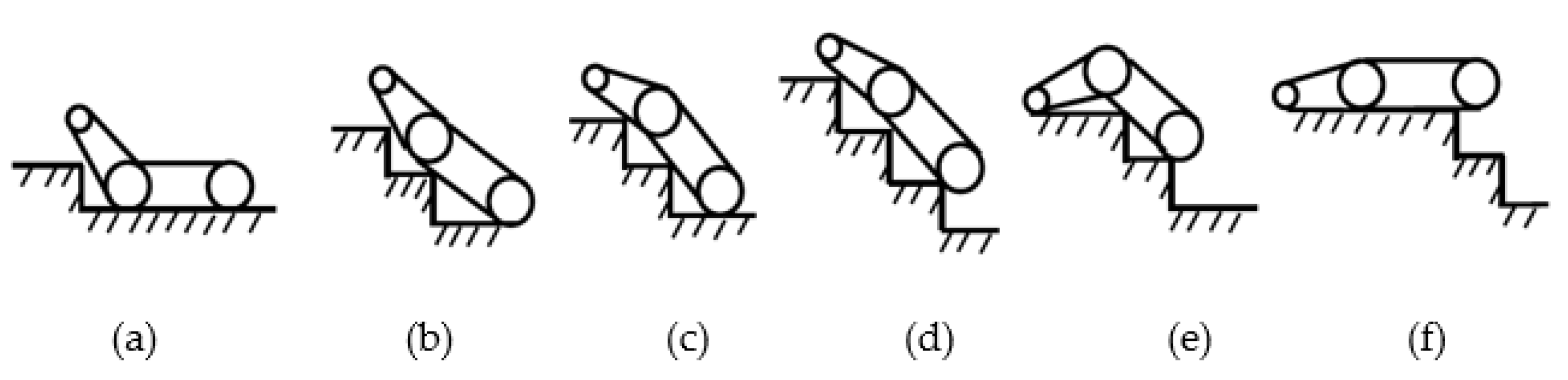
4.3. Analysis of the Rocker Arm in a Retracted State during Stairs Climbing

The ability to climb stairs, shown in Figure 10, is an important performance index of coal mine search-and-rescue robots [30].
Figure 11 shows a partial schematic diagram of the robot climbing a stairs.
It can be concluded from Figure 11 that for the robot to continuously climb the stairs, it needs to meet the following conditions:
L 3 > H
L 1 + L 3 > 2 H 2 + T 2
Here, after satisfying Formula (11), the robot can put the rocker arm on the first step. After satisfying Formula (12), the robot will be able to climb the stairs continuously. Equations (11) and (12) are necessary conditions for the robot to climb the stairs continuously. Through field measurements in the laboratory building, the relevant data were obtained: H = 164 mm, and T = 283 mm. At this point, 2 H 2 + T 2 = 654.17 mm and L1 + L3 = 810 mm. The design parameters of the robot then satisfy Equations (11) and (12), so the robot can climb the stairs smoothly.

4.4. Analysis of the Rocker Arm in an Extended State during Stairs Climbing

The ability to climb stairs, shown in Figure 12:
Figure 12 is a diagram of the stairs climbing process when the rocker arm is extended. By adjusting the hydraulic mechanism, the rocker arm is fully extended forward so that the rocker arm and the main crawler are in the same straight line, which increases the length of the search-and-rescue robot. As a result, the contact between the robot and the stairs will become longer, thereby improving the climbing ability and stability of the robot during the stairs climbing process.
Figure 13 shows a partial schematic diagram of the robot climbing a stairs.
It can be concluded from Figure 13 that for the robot to continuously climb the stairs, it needs to meet the following conditions:
L 11 + L 3 > 2 H 2 + T 2
Through calculation, it is obtained that L11 + L3 = 1010 mm, and the value of 2 H 2 + T 2 is unchanged, which satisfy Equations (11) and (13), so the robot can also climb the stairs smoothly.
After analysis, it can be seen that when the robot rocker arm is fully extended, the sum of the robot body and the rocker arm is the longest. Understandably, after adding the hydraulic mechanism, the robot’s ability to climb the stairs will be improved. This shows that the ability of the robot to overcome obstacles is significantly improved after adding a hydraulic mechanism.

4.5. Experimental Testing

In this paper, experimental tests were conducted with a conventional tracked robot to verify the reliability of the simulation data through experiments.
As shown in Figure 14, a conventional tracked robot of the same size was used here for the experiment. Through the experiment, it was found that the maximum height of the robot over the barrier was about 195 mm, and this result was higher than the simulation result. This is because the robot used in the experiment was equipped with some equipment at the upper end, which made the robot’s center of gravity higher, thus increasing the height of the robot over the barrier.

5. Discussion

Search-and-rescue robots need to face complex rescue environments, and it is necessary for them to be able to exhibit greater obstacle-crossing performance in a limited environment in the rescue process. The two-stage crawler search-and-rescue robot designed in this paper has a better obstacle-crossing capability than the traditional two-stage crawler robot, which can improve the rescue efficiency. The main compared parameters are shown in Table 2.
In this paper, a hydraulic mechanism is added to an existing two-stage crawler search-and-rescue robot to enhance the robot’s barrier-crossing capability. However, this solution faces some challenges:
1. The overall mass of the robot also increases with the addition of the hydraulic mechanism, which reduces the mobility of the robot and thus affects the rescue efficiency.
2. As the rescue environment is more complex, the added hydraulic mechanism will be affected by the external environment, which will also affect the rescue efficiency.
3. The position of the robot’s center of gravity affects the robot’s ability to cross obstacles. The robot’s structure can be improved to raise its center of gravity, which will further enhance the robot’s ability to cross obstacles.
In response to these challenges, further research will take this as an entry point to continue optimizing the overall structure of the rescue robot, which can then be better adapted to a rescue environment.

6. Conclusions

In this paper, a two-stage crawler search-and-rescue robot is designed. The front rocker arm can adjust the movement posture. At the same time, the front rocker arm and the main body of the robot are connected by a hydraulic mechanism, which can realize the expansion and contraction of the rocker arm, improving the obstacle climbing ability of the search-and-rescue robot. The coordinate systems of each part and the whole of the robot are established through RPY transformation, and the coordinates of the mass center of the robot when the rocker arm is extended and retracted are calculated. Through simulation analysis, the theoretical maximum obstacle height of the robot in the two states is obtained. Through the analysis, it is found that when the robot’s rocker arm extends, its obstacle-climbing ability is significantly improved. The detailed simulation results are as follows:
1. The designed robot has a maximum crossing height of 219.01 mm when crossing the obstacle, which is 16.7% higher than a conventional search-and-rescue robot of the same size.
2. The designed robot has a maximum climbing length of 1100 mm when climbing stairs, which is a 24.7% improvement in climbing capacity compared to conventional search-and-rescue robots of the same size.
This provides a new solution for the design of search-and-rescue robots in the future, which at the same time also provides a theoretical basis for the motion control of robots in actual disaster relief and rescue.

Author Contributions

Methodology, L.S. and H.W.; investigation, validation, formal analysis, writing—original draft, L.S.; software, H.W. and T.P.; writing—review and editing, H.W.; funding acquisition, H.W. and H.S.; supervision, project administration, H.S. and Y.L.; investigation, editing, Y.L.; editing, T.P. All authors have read and agreed to the published version of the manuscript.

Funding

This research was funded by the “Experimental technology research and development project” of Nanjing University of Aeronautics and Astronautics (No. SYJS202207Y), The First Batch of Industry University Cooperation Collaborative Education Projects of the Ministry of Education in 2021 (No. 202101042005), and The Fundamental Research Funds for the Central Universities (No. NS2022094).

Institutional Review Board Statement

Not applicable.

Informed Consent Statement

Not applicable.

Data Availability Statement

The data used to support the findings of this study are available from the corresponding author upon request.

Acknowledgments

We are grateful to the editors and the reviewers for their insightful comments and suggestions.

Conflicts of Interest

The authors declare no conflict of interest.

References

  1. Ge, S. Application of robot in “9.11” rescue operation. Fire Tech. Prod. Inf. 2003, 7, 44–47. [Google Scholar]
  2. Yamauchi, B.M. Daredevil: Ultra-wideband radar sensing for small UGVs. In Proceedings of the Conference Unmanned Systems Technology IX.65610B, Orlando, FL, USA, 2 May 2007. [Google Scholar]
  3. Restas, A. Drone Applications for Supporting Disaster Management. World J. Eng. Technol. 2015, 3, 316–321. [Google Scholar] [CrossRef] [Green Version]
  4. Quaritsch, M.; Kruggl, K.; Wischounig-Strucl, D.; Bhattacharya, S.; Shah, M.; Rinner, B. Networked UAVs as aerial sensor network for disaster management applications. E I Elektrotechnik Und Inf. 2010, 127, 56–63. [Google Scholar] [CrossRef]
  5. Habib, M.K.; Baudoin, Y.; Nagata, F. Robotics for rescue and risky intervention. In Proceedings of the IECON 2011–37th Annual Conference of the IEEE Industrial Electronics Society, Melbourne, VIC, Australia, 7–10 November 2011; pp. 3305–3310. [Google Scholar]
  6. Surve, J.; Mehta, V.; Rawat, A.; Kamaliya, K.; Deb, D. Low Cost 2 MHz Transmitter for the Detection of Human Trapped Under the Snow. In Proceedings of the International Conference on Power, Control and Communication Infrastructure 2019 (ICPCCI2019), Ahmedabad, Gujarat, India, 4–5 July 2019. [Google Scholar]
  7. Wei, J.; Jia, G.; Ma, H. Simulation Analysis of the Virtual Prototyping of a Mine Rescue Robot. Mech. Sci. Technol. Aerosp. Eng. 2008, 27, 1369–1379. [Google Scholar]
  8. Wang, Y.; Zhu, H.; Wang, Y.S.; Cheng, G.; Li, Y.W. Current Status and Technical Problems in Research of Coal Mine Rescue Robot. Coal Mine Mach. 2007, 4, 107–109. [Google Scholar]
  9. Wang, Z.; Dong, E.; Jin, H.; Wang, H.; Lu, D.; Xu, M.; Yang, J. System dynamics simulation and prototype design of a high efficient legged robot based on hybrid-driven mechanism. In Proceedings of the 2013 IEEE/ASME International Conference on Advanced Intelligent Mechatronics, Wollongong, NSW, Australia, 9–12 July 2013. [Google Scholar]
  10. Luo, Q.S.; Liu, Y.S.; Niu, K.; Wu, F.; Li, G.H. Research on new wheel-legged robot. J. Dalian Univ. Technol. 2011, 51, 88–92. [Google Scholar]
  11. Huang, B.; Wang, P.F.; Sun, L.N. Design and Analysis of a Hybrid Quadruped Robot. Mach. Des. Res. 2006, 05, 49–53. [Google Scholar]
  12. Wang, P.; Bo, H.; Sun, L. Walking research on multi-motion mode quadruped bionic robot based on moving ZMP. In Proceedings of the Mechatronics and Automation, 2005 IEEE International Conference, Niagara Falls, ON, Canada, 29 July–1 August 2005. [Google Scholar]
  13. Hashimoto, K.; Hosobata, T.; Sugahara, Y.; Mikuriya, Y.; Sunazuka, H.; Kawase, M.; Lim, H.; Takanishi, A. Realization by Biped Leg-wheeled Robot of Biped Walking and Wheel-driven Locomotion. In Proceedings of the IEEE International Conference on Robotics & Automation, Barcelona, Spain, 18–22 April 2005. [Google Scholar]
  14. China Electricity Council. Data List of National Power Industry Statistical Express in 2016; China Electricity Council: Beijing, China, 2017; pp. 22–29. [Google Scholar]
  15. Casper, J.L.; Micire, M.; Murphy, R.R. Issues in intelligent robots for search and rescue. In Proceedings of the Unmanned Ground Vehicle Technology II International Society for Optics and Photonics, Orlando, FL, USA, 24–28 April 2000. [Google Scholar]
  16. Ortigoza, R.S.; Marcelino-Aranda, M.; Ortigoza, G.S.; Guzman, V.M.H.; Molina-Vilchis, M.A. Wheeled Mobile Robots: A review. IEEE Lat. Am. Trans. 2012, 10, 2209–2217. [Google Scholar] [CrossRef]
  17. Liu, S.; Sun, D. Minimizing Energy Consumption of Wheeled Mobile Robots via Optimal Motion Planning. IEEE/ASME Trans. Mechatron. 2014, 19, 401–411. [Google Scholar] [CrossRef]
  18. Jiang, H.; Xu, G.; Zeng, W.; Gao, F.; Chong, K. Lateral Stability of a Mobile Robot Utilizing an Active Adjustable Suspension. Appl. Sci. 2019, 9, 4410. [Google Scholar] [CrossRef] [Green Version]
  19. Zeng, X.; Li, D.; Zhang, X. Quadruped Robot Walking Control on Trench-like Noncontinuous Terrain. Robot 2011, 33, 700–705. [Google Scholar]
  20. Wang, Z.F.; Ma, S.G.; Li, B.; Wang, Y.C. Simulation and Experimental Study of an Energy-based Control Method for the Serpentine Locomotion of a Snake-like Robot. Acta Autom. Sin. 2011, 37, 604–614. [Google Scholar]
  21. Sanfilippo, F.; Azpiazu, J.; Marafioti, G.; Transeth, A.A.; Stavdahl, Ø.; Liljebäck, P. Perception-Driven Obstacle-Aided Locomotion for Snake Robots: The State of the Art, Challenges and Possibilities. Appl. Sci. 2017, 7, 336. [Google Scholar] [CrossRef] [Green Version]
  22. Yang, J.I.; Huo, G.Q. Research Status of Track-type Mobile Robots. For. Mach. Woodwork. Equip. 2012, 40, 7–10. [Google Scholar]
  23. Endo, G.; Hirose, S. Study on Roller-Walker–Adaptation of characteristics of the propulsion by a leg trajectory-. J. Robot. Soc. Jpn. 2008, 26, 691–698. [Google Scholar]
  24. Endo, G.; Hirose, S. Study on Roller-Walker—Improvement of Locomotive Efficiency of Quadruped Robots by Passive Wheels. Adv. Robot. 2012, 26, 969–988. [Google Scholar] [CrossRef] [Green Version]
  25. Ding, L. Key Technology Analysis of Big Dog Quadruped Robot. J. Mech. Eng. 2015, 51, 1–23. [Google Scholar] [CrossRef]
  26. Raibert, M.; Blankespoor, K.; Nelson, G.; Playter, R. BigDog, the Rough-Terrain Quadruped Robot. IFAC Proc. Vol. 2008, 41, 10822–10825. [Google Scholar] [CrossRef]
  27. Zhu, J.H. Design and Research on the Walking Device of the Telescopic Wheel Track Swith on The Small; Guangxi University: Nanning, China, 2016; pp. 11–14. [Google Scholar]
  28. Cai, Z.X.; Xie, B. Rbotics; Tsinghua University Press: Beijing, China, 2015; pp. 46–58. [Google Scholar]
  29. Han, H.U.; Cheng, J.M.; Niu, Z.G. Analysis on Obstacle-surmounting of Coal Mine Detection Robot Based on RPY. Coal Mine Mach. 2013, 34, 109–111. [Google Scholar]
  30. Qiao, F.B.; Yang, R.Q. Analysis on the Stair climbing Ability of Six wheeled Mobile Robot. Robot 2004, 26, 301–305. [Google Scholar]
Figure 1. Structure of a conventional search and rescue robot.
Applsci 12 10485 g001
Figure 2. Design scheme of the search-and-rescue robot. 1 indicates the main crawler of the robot, 2 is the rocker arm crawler, and 3 is the hydraulic mechanism between the rocker arm and the robot body.
Applsci 12 10485 g002
Figure 3. Simplified model of the search-and-rescue robot: (a) simplified model when the rocker arm is retracted, and (b) simplified model with the swing arm extended.
Applsci 12 10485 g003
Figure 4. The process of crossing a step. (a) the start of the climbing process, and the rocker arm starts to touch the step; (b) the robot is ready to climb, and the rocker arm is already on the step; (c) crossing over; (d) the critical point of climbing—at this point, the center of gravity of the robot and the contact point are on the same vertical line; (e) the end of the climb, at which point the robot has climbed the step completely.
Applsci 12 10485 g004
Figure 5. Process of crossing a step.
Applsci 12 10485 g005
Figure 6. The relationship between H and η, γ: (a) Three-dimensional map; (b) the relationship between H and γ; and (c) the relationship between H and η.
Applsci 12 10485 g006aApplsci 12 10485 g006b
Figure 7. The process of navigating a step. (a) the start of the climbing process, and the rocker arm starts to touch the step; (b) the robot is ready to climb, and the rocker arm is already on the step; (c) crossing over; (d) the critical point of climbing—at this point, the center of gravity of the robot and the contact point are on the same vertical line; (e) the end of the climb, at which point the robot has climbed the step completely.
Applsci 12 10485 g007
Figure 8. Process of crossing a step.
Applsci 12 10485 g008
Figure 9. Three-dimensional map of the relationship between H and η, γ. (a) Three-dimensional map; (b)the relationship between H and γ; (c) the relationship between H and η.
Applsci 12 10485 g009
Figure 10. The entire process of climbing a stairs. (a) the start of stairs climbing when the rocker is on the first step; (be) the stairs climbing process; (c) the three-point contact of the first step, the second step, and the ground; (f) the completion of the stairs climbing process and the robot is fully on the top step.
Applsci 12 10485 g010
Figure 11. Process of climbing a stairs. (a) the point where the robot rocker arm starts to touch the first step; (b) the robot climbing the stairs.
Applsci 12 10485 g011
Figure 12. The whole process of climbing a stairs. (a) The start of stairs climbing when the rocker is on the first step; (be) the stairs climbing process; (c) the three-point contact of the first step, the second step, and the ground; (f) the completion of the stairs climbing process and the robot is fully on the top step.
Applsci 12 10485 g012
Figure 13. Process of climbing a stairs. (a) the point where the robot rocker arm starts to touch the first step; (b) the robot climbing the stairs.
Applsci 12 10485 g013
Figure 14. Robot overcoming obstacles.
Applsci 12 10485 g014
Table 1. Robot parameter table.
Nomenclature
G1Center of gravity of the main body of the robot
Center of gravity of the robot’s rocker arm
The minimum center distance of the large wheels at both ends when the rocker arm is retracted and extended
The maximum center distance of the large wheels at both ends when the rocker arm is retracted and extended
G2
L1
L11
L2Distance from the center of gravity of the robot body to the center of the rear wheel
L3Distance between the centers of the two wheels on the robot rocker arm
L4Distance from the center of gravity of the rocker arm to the center of the rear wheel of the rocker arm
γSwing angle of the rocker arm
ηPitch angle of the robot body
RBig wheel radius
rSmall wheel radius
Table 2. Comparison of parameters before and after improvement.
ParameterBefore the
Improvement
After the
Improvement
Change
Rocker arm length300 mm300 mm0
Main body510 mm510 mm0
Max length810 mm1010 mm24.7%
Max overrun height187.74 mm219.01 mm16.7%
Publisher’s Note: MDPI stays neutral with regard to jurisdictional claims in published maps and institutional affiliations.

