
Numerical and Experimental Study on the Member Performance and Stability Bearing Capacity of Wheel Coupler Formwork Supports


Abstract
:1. Introduction
2. Experimental Analysis of the Bearing Capacity of the Horizontal Bar
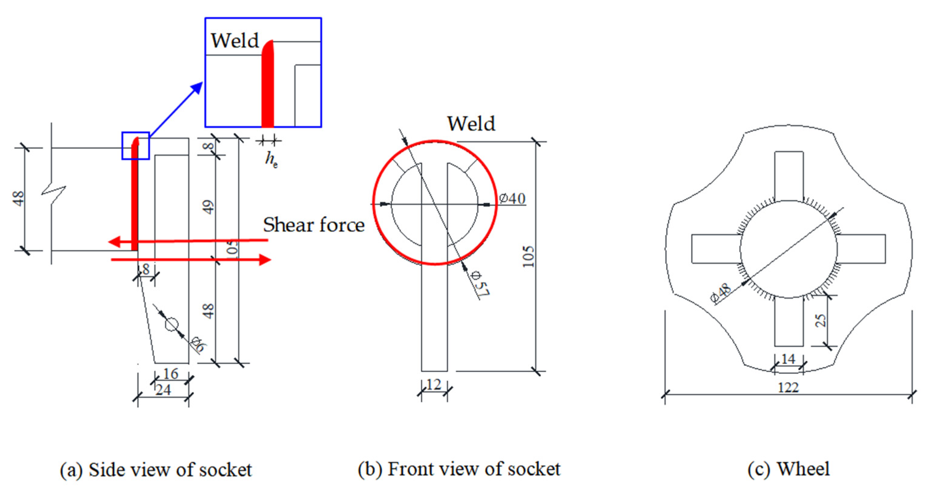
2.1. Eccentric Tensile Properties of the Socket on the Horizontal Bar
2.1.1. Theoretical Value of the Eccentric Tensile Bearing Capacity of the Socket on the Horizontal Bar
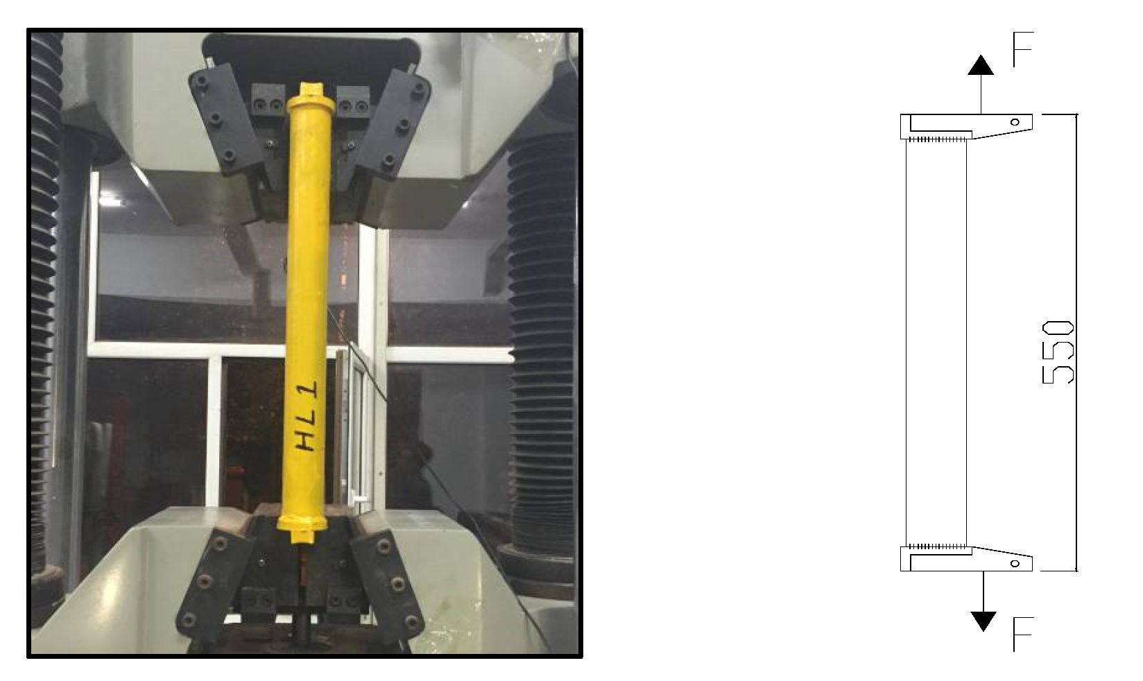
2.1.2. Experimental Design
2.1.3. Experimental Results and Analysis
2.1.4. Finite Element Comparative Analysis of Eccentric Tensile Properties of the Socket on the Horizontal Bar
- 1.
- According to the finite element analysis, the deformation and displacement of the sockets on the horizontal bar under normal working conditions were obtained, and the specific values are shown in Table 2.
- 2.
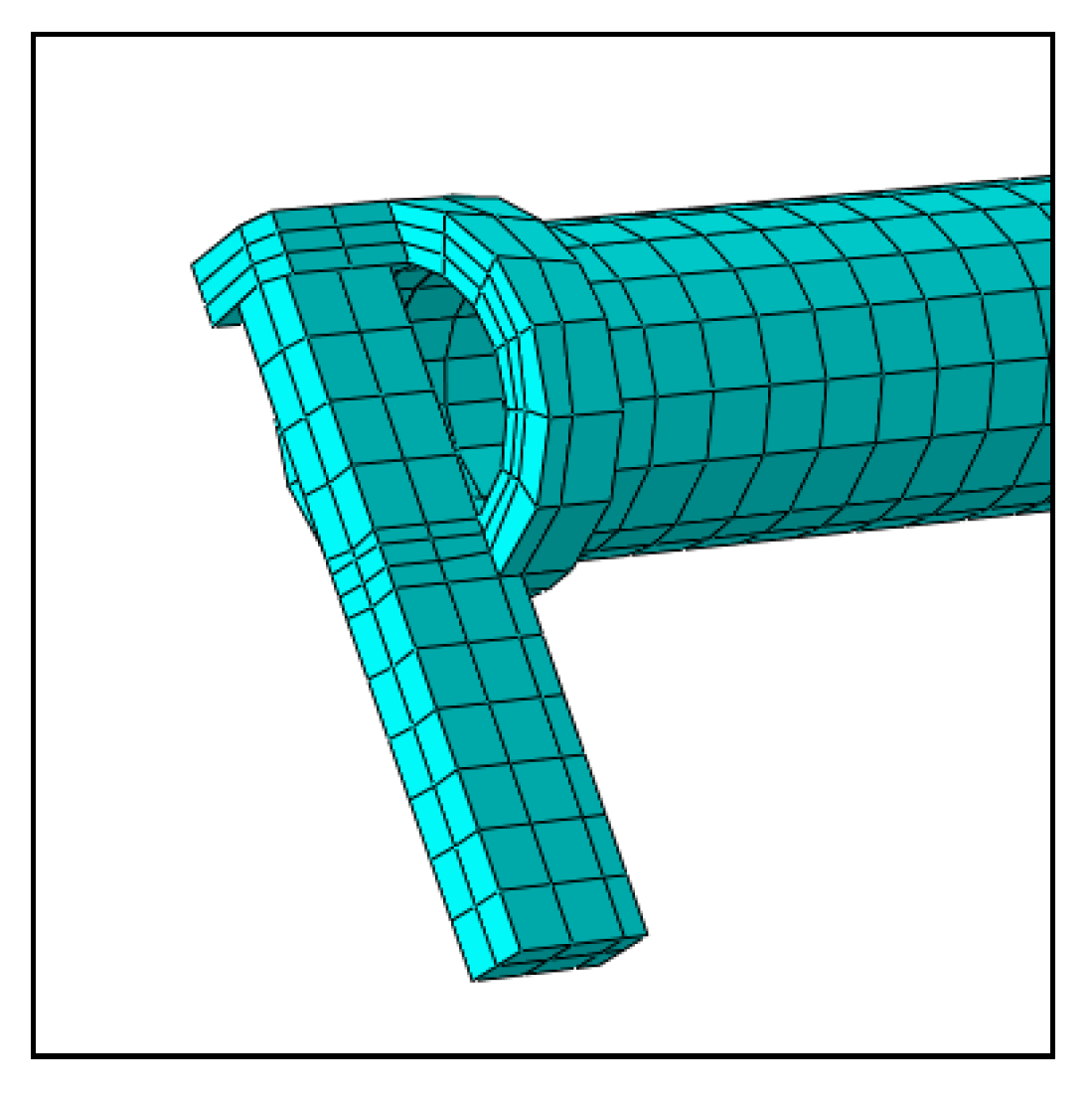
- Regarding stress distribution, according to the simulation analysis and experimental results, when the socket on the horizontal bar was pulled eccentrically, the stress concentration area was located at the connection between the socket and the horizontal bar. The results of the simulation analysis were in good agreement with the experimental results.
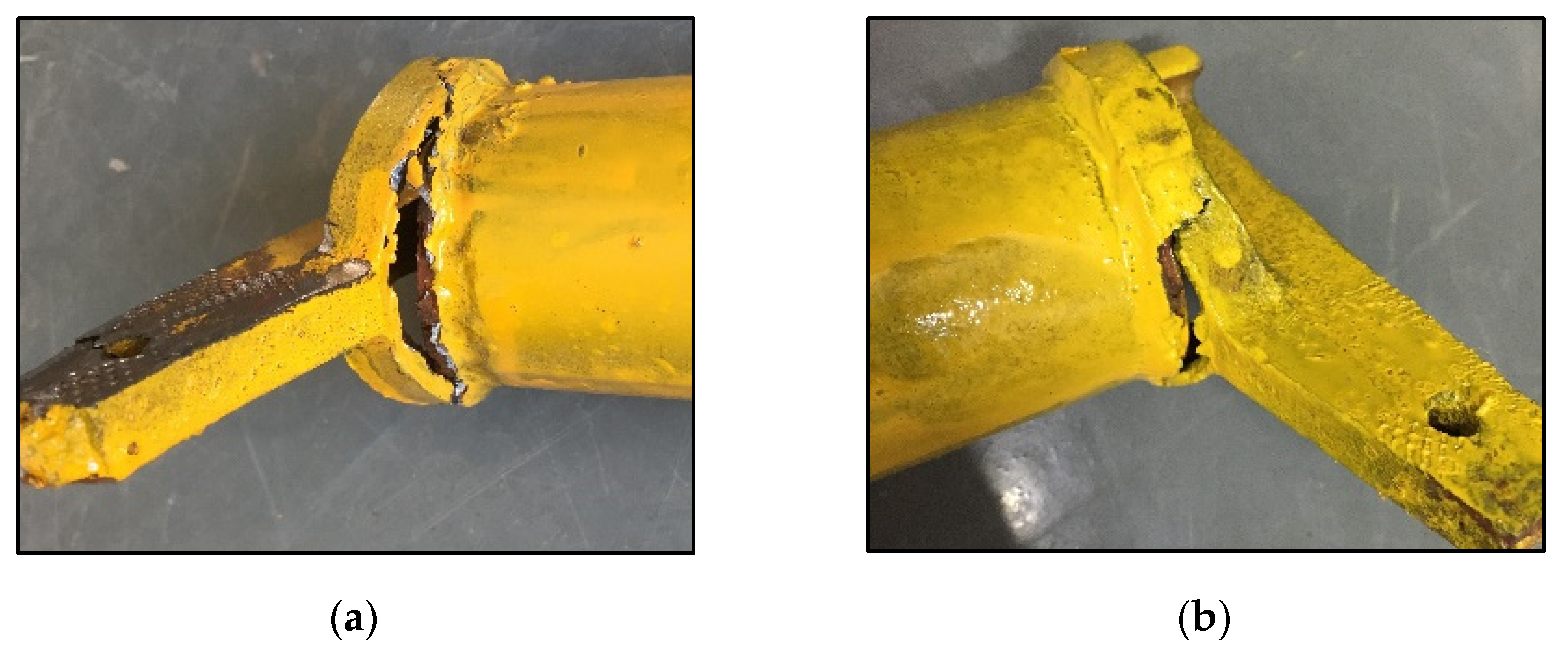
- 3.
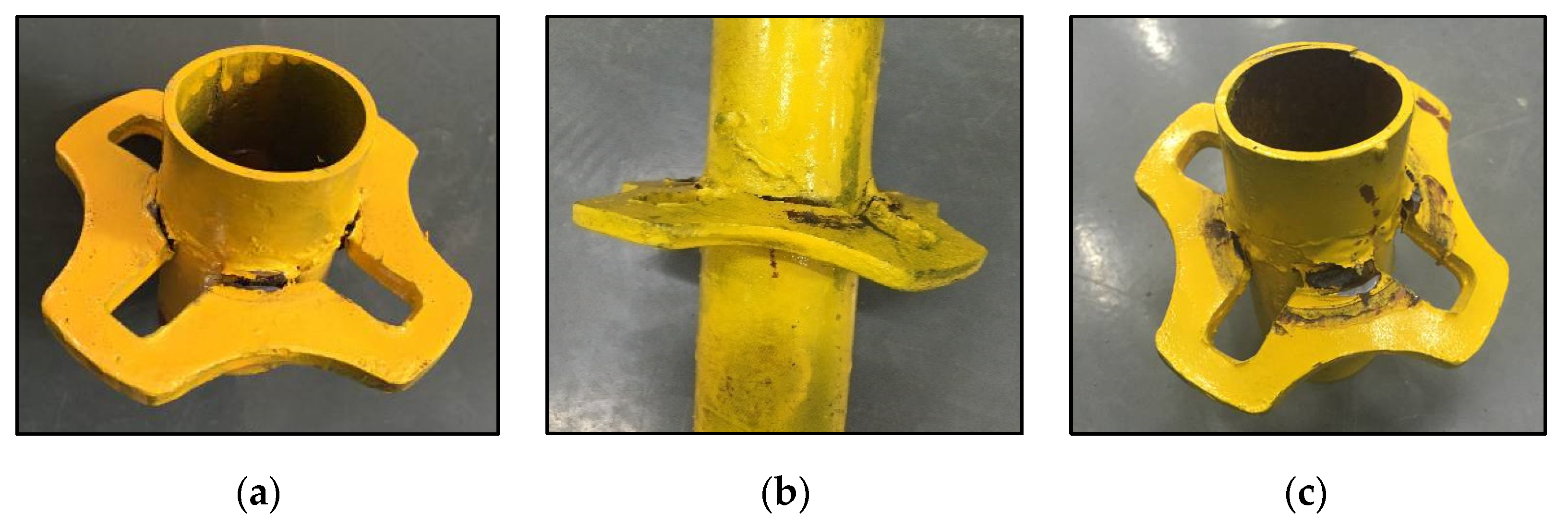
- Regarding failure morphology, according to the simulation analysis and experimental results for the eccentric tension of the socket on the horizontal bar, stress concentrations led to plastic deformation at the connection. The plastic deformation increased continuously and eventually led to the loss of the bearing capacity of the specimen. The results showed that under the normal working state of the formwork support, the connection between the socket and the horizontal bar was prone to damage; it was the weak point of the bearing capacity of the horizontal bar of the formwork support.
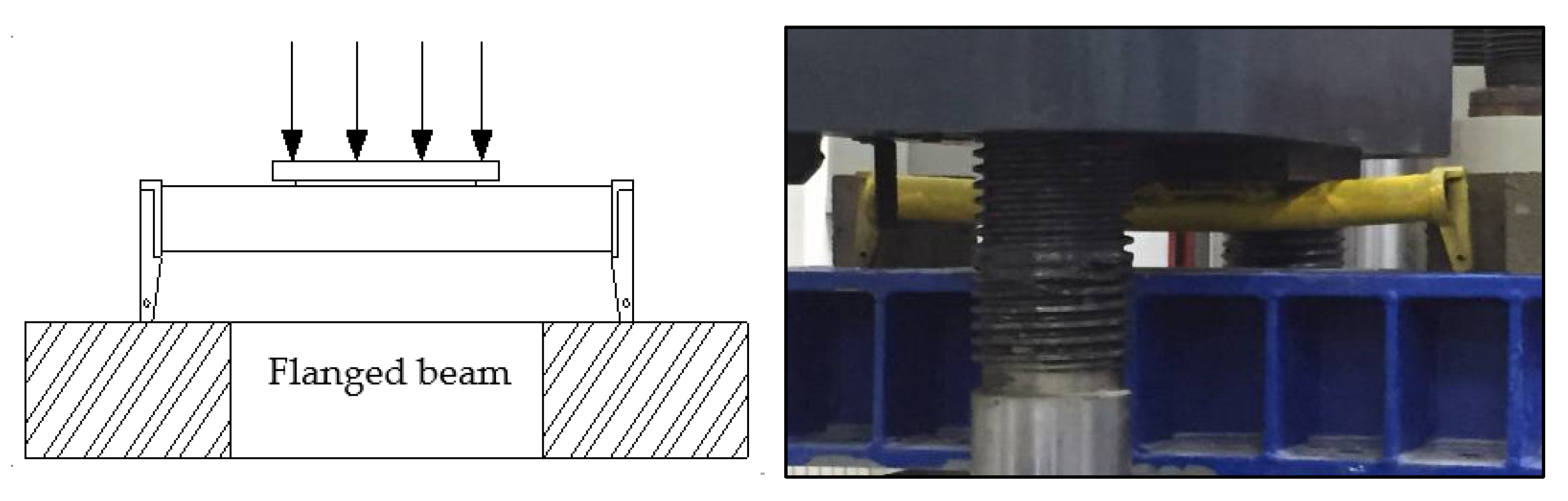
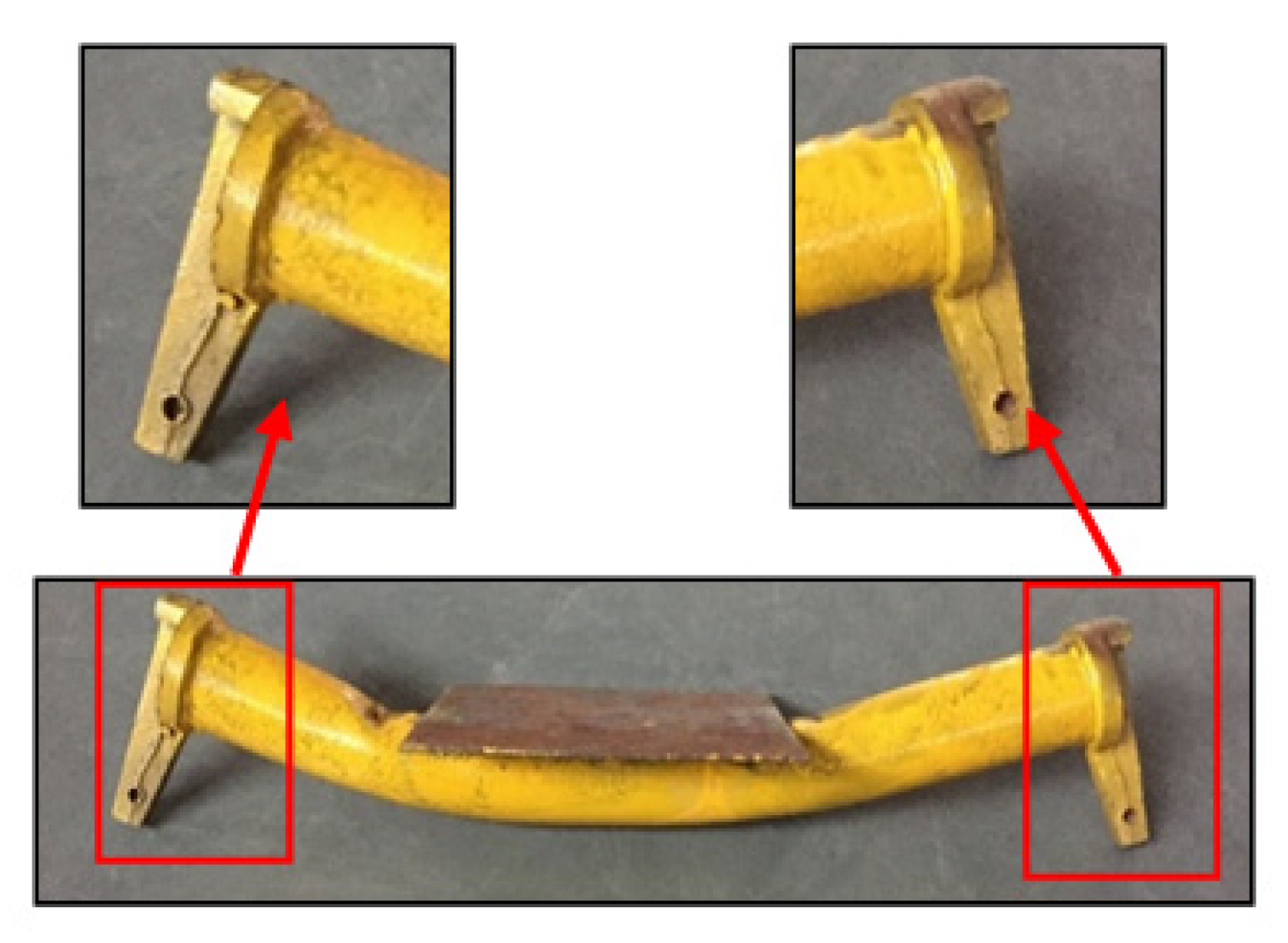
2.2. Bending Performance of the Horizontal Bar
2.2.1. Experimental Design
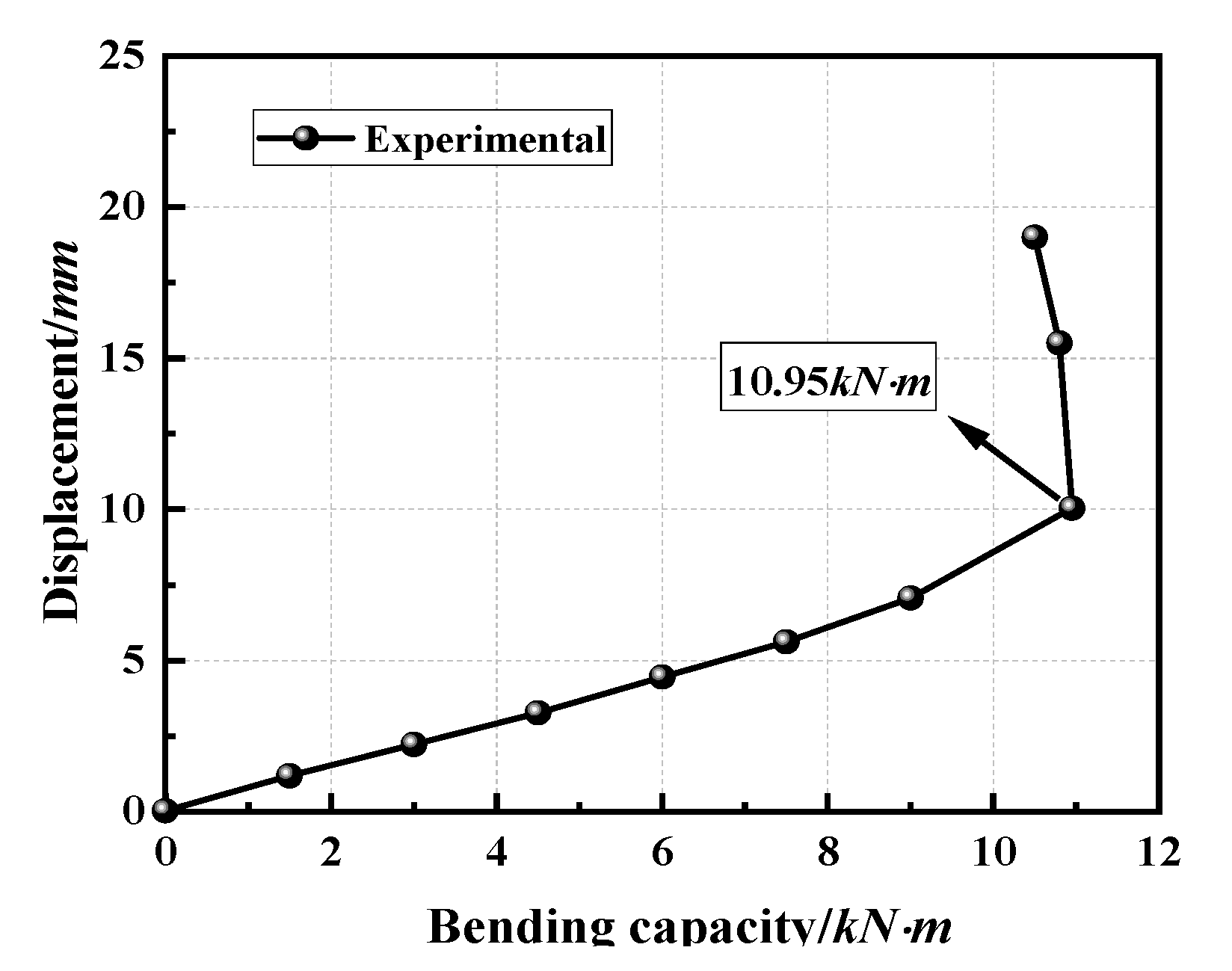
2.2.2. Experimental Results and Analysis
3. Experimental Analysis of the Bearing Capacity of the Vertical Member
3.1. Experimental Analysis of the Shear Capacity of the Wheel on the Vertical Pole
3.1.1. Theoretical Value of the Wheel Shear Capacity
- 1.
- When the four sides of the wheel are sheared,
- 2.
- When the three sides of the wheel are sheared,
- 3.
- When the two sides of the wheel are sheared,
3.1.2. Experimental Design
3.1.3. Experimental Results and Analysis
3.1.4. Finite Element Comparative Analysis of the Shear Capacity of the Wheel on the Vertical Pole
- The comparison of the results for the wheel shear capacity of the experiment and the finite element analysis showed that the curve fit was accurate (Figure 15), which verified the accuracy of the finite element model.
- Regarding stress distribution, when the wheel was subjected to shear force, the area of stress concentration was at the connection between the wheel and the vertical pole. The results of the simulation analysis were consistent with the experimental results. Plastic deformation occurred at the joint due to stress concentration. Therefore, when the wheel was sheared, the area prone to damage was the weld between the wheel and the vertical pole.
3.2. Experimental Analysis of the Shear Capacity of the Sleeve on the Vertical Pole
3.2.1. Theoretical Value of Sleeve Shear Capacity
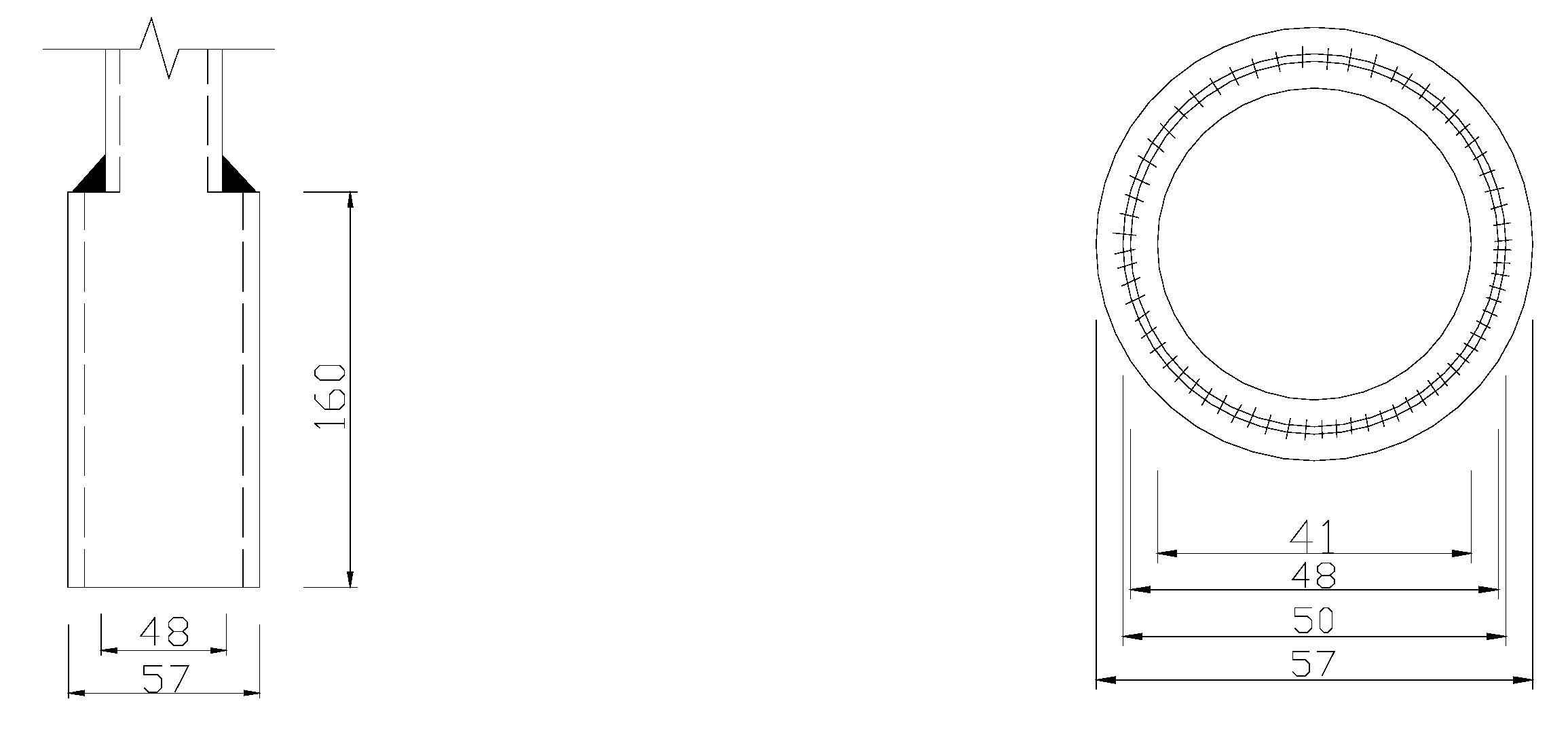
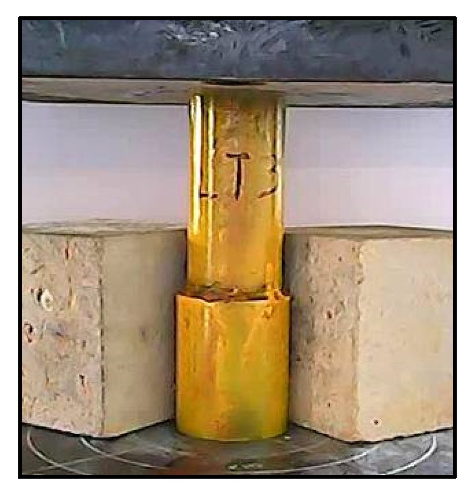
3.2.2. Experimental Design
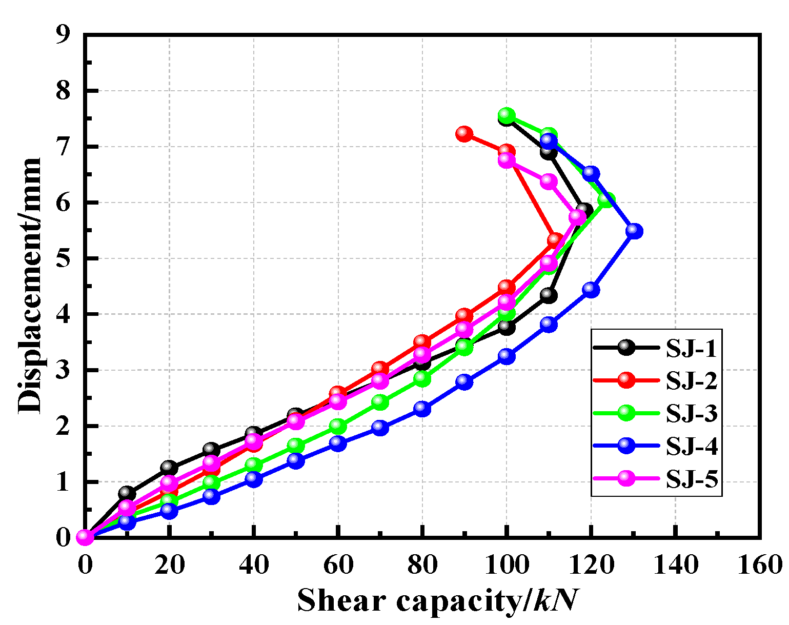
3.2.3. Experimental Results and Analysis
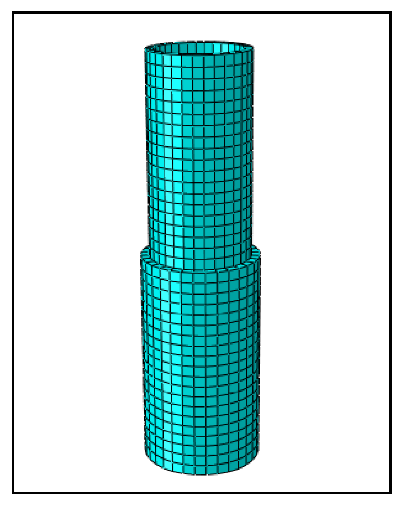
3.2.4. Finite Element Comparative Analysis of the Shear Capacity of the Sleeve on the Vertical Pole
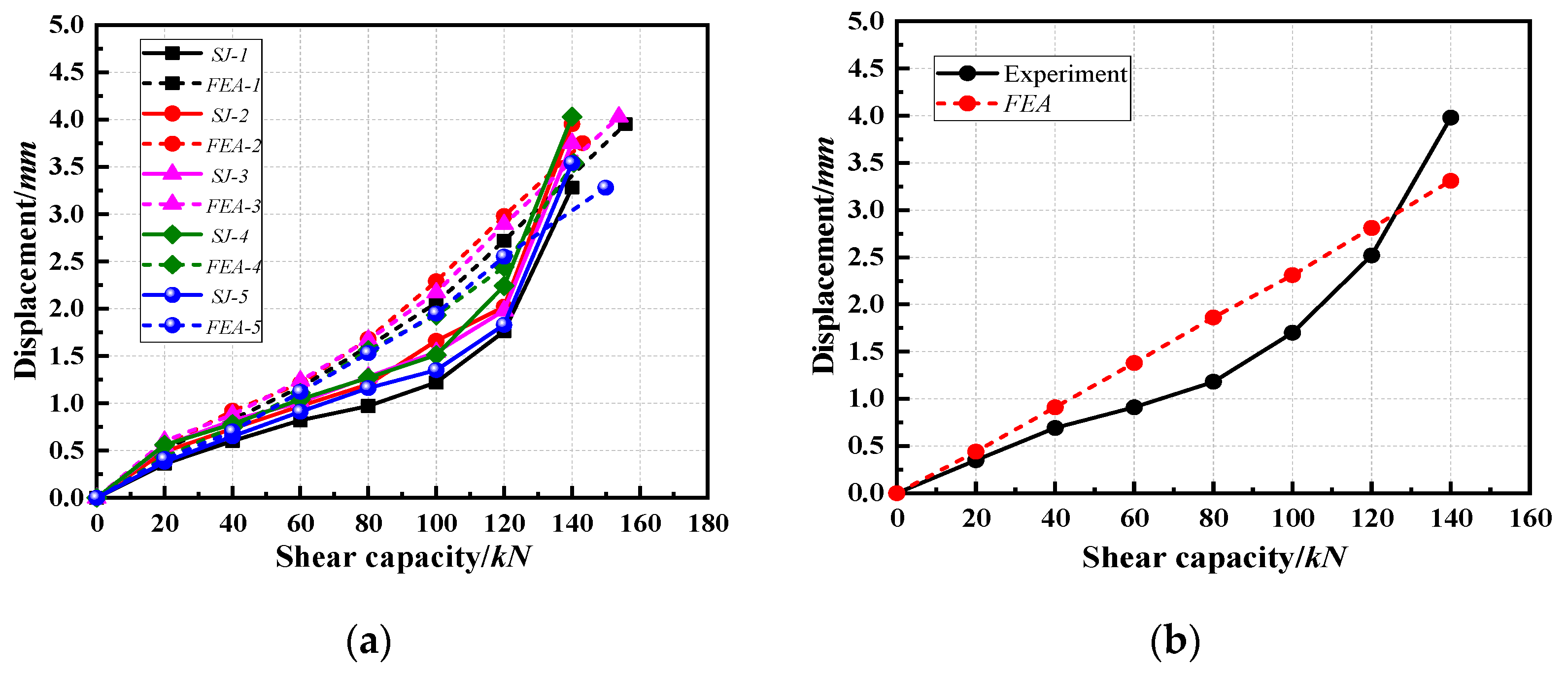
- 1.
- Regarding shear capacity, the results of the were compared with the average values of the five groups of specimens, and Figure 20b was obtained. The trends of the two graphs of the simulated and experimental values were different. The experimental load–displacement curve increased slowly in the middle of the loading period, while the load–displacement curve obtained by the finite element method increased linearly throughout the experiment, which indicated the necessity of establishing the welding unit when studying the shear capacity of the sleeve. However, the results for the ultimate shear capacity were very accurate, which verified the accuracy of the finite element model to predict the ultimate shear capacity of the sleeve.
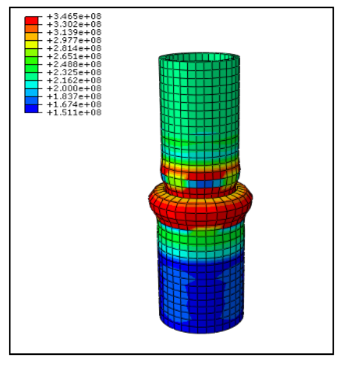
- 2.
- Regarding stress distribution, according to the simulation analysis and experimental results, when the sleeve was sheared, the stress concentration area was located mainly in the main material near the connection between the sleeve and the vertical pole. The results were consistent for the simulation analysis and experiment.
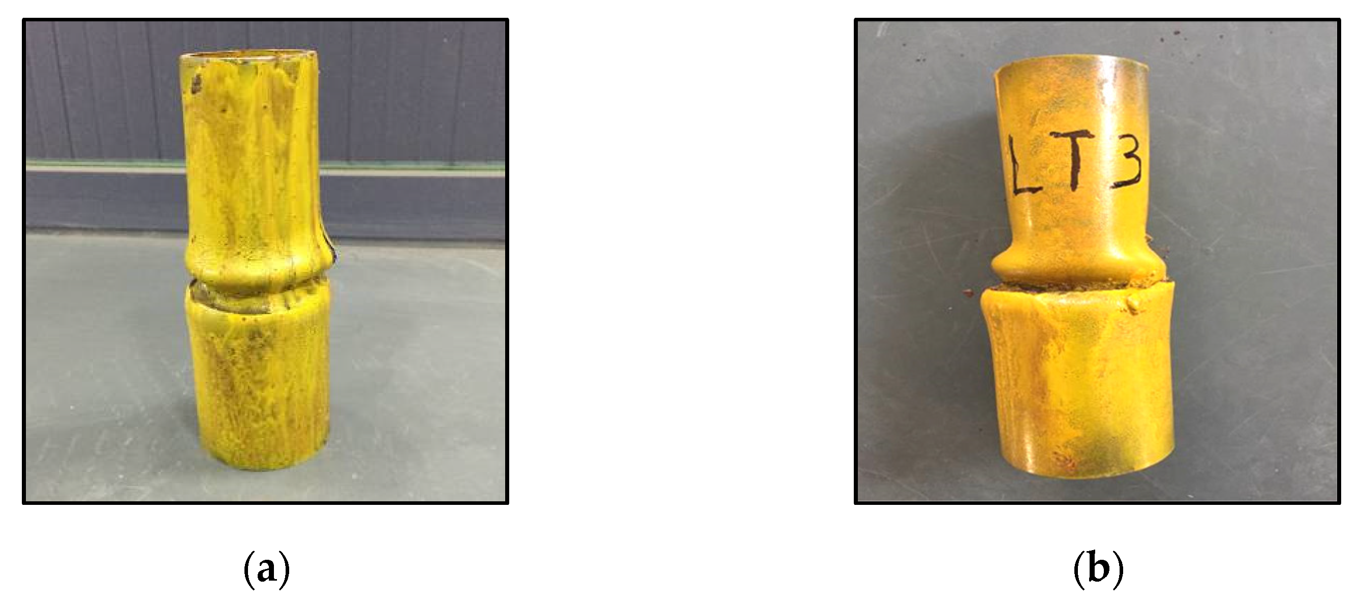
- 3.
- Regarding failure mode, according to the simulation analysis and experimental results, the sleeve shear failure mode was the result of stress concentration that led to different degrees of plastic buckling deformation of the vertical pole and the sleeve; this buckling eventually led to the loss of bearing capacity by the specimen. The results showed that the bearing capacity of the sleeve was stronger under shear force.
4. Results and Discussion
4.1. Constitutive Experiment
4.2. Theoretical Value of the Stability Bearing Capacity of the Vertical Pole
- Calculation of the axial compression stability bearing capacity of the double-layer 1.2 m vertical pole: According to = 78.77, = 0.696.
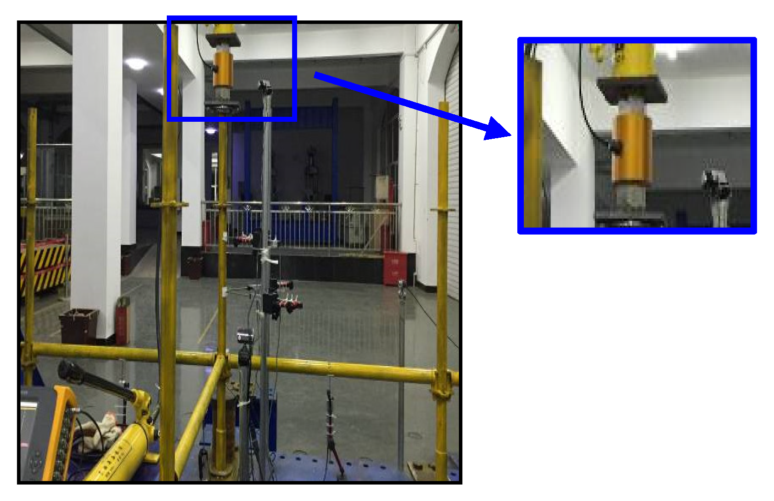
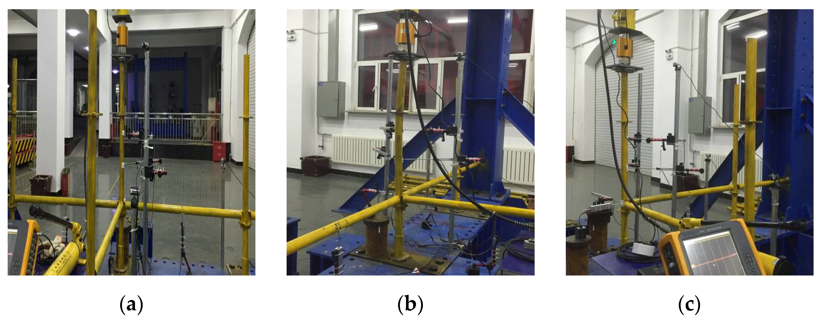
4.3. Experimental Design
4.4. Experimental Results and Analysis
4.5. Finite Element Analysis and Verification of Stability Bearing Capacity Experiments of Single- and Double-Layer Vertical Poles
4.5.1. Establishment of the Numerical Model
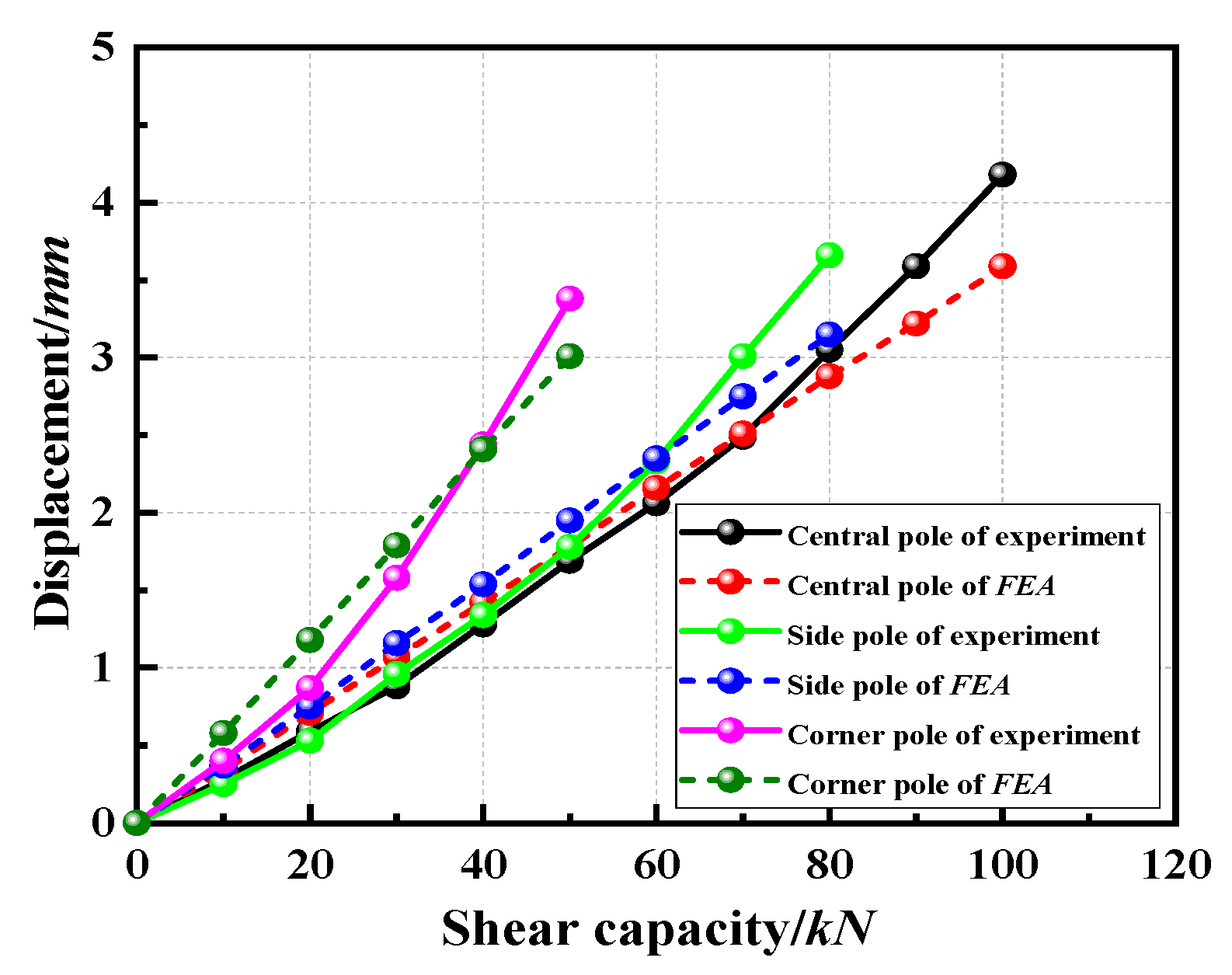
4.5.2. Finite Element Comparative Analysis
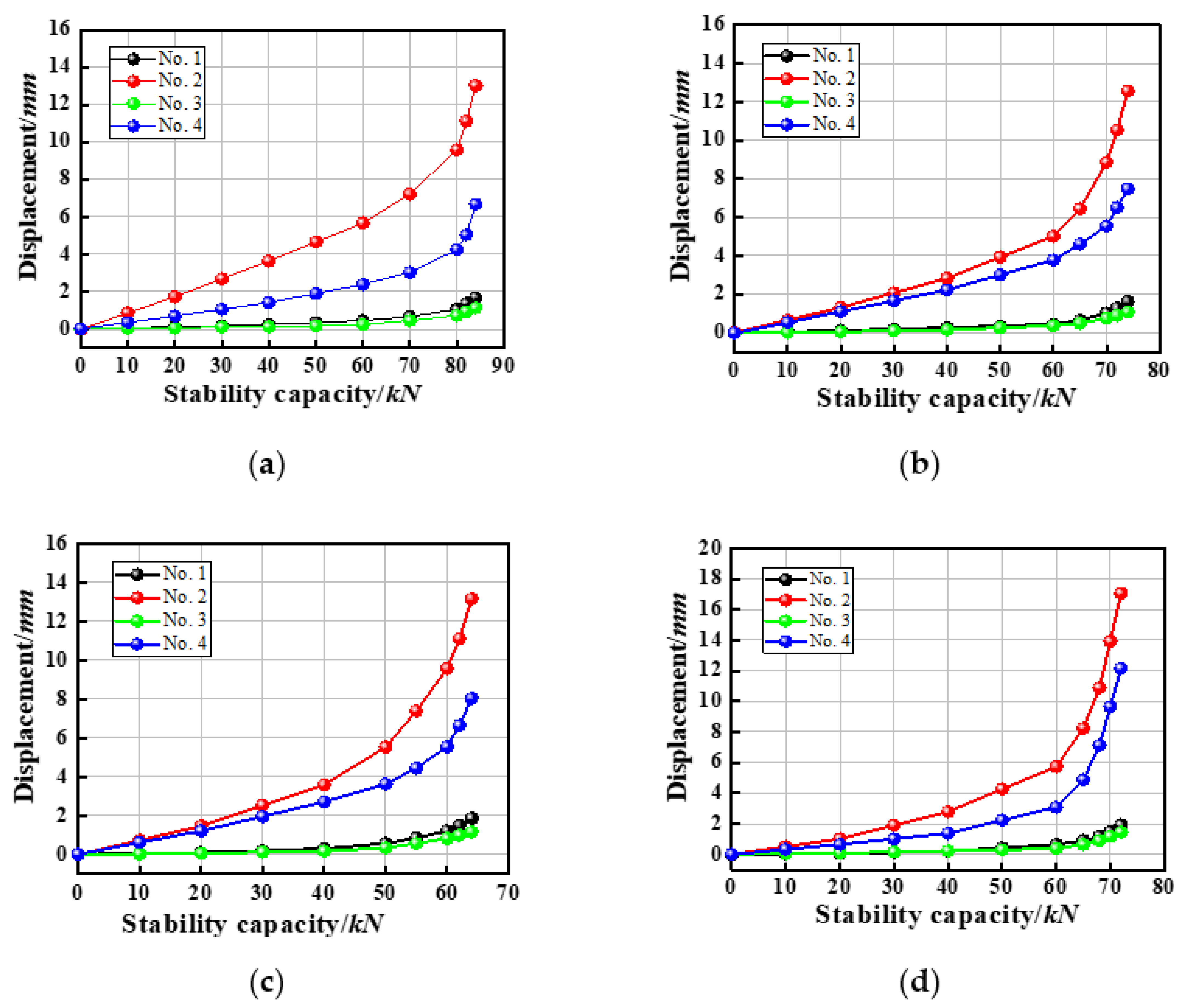
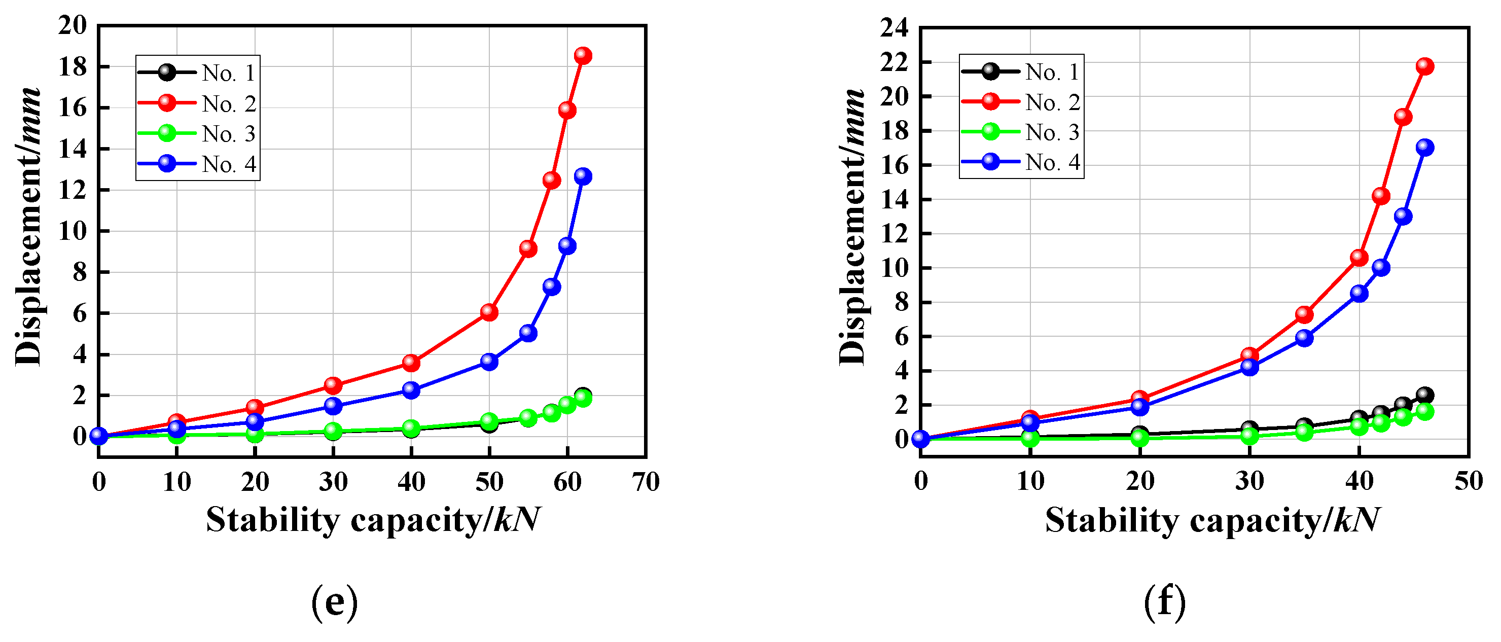
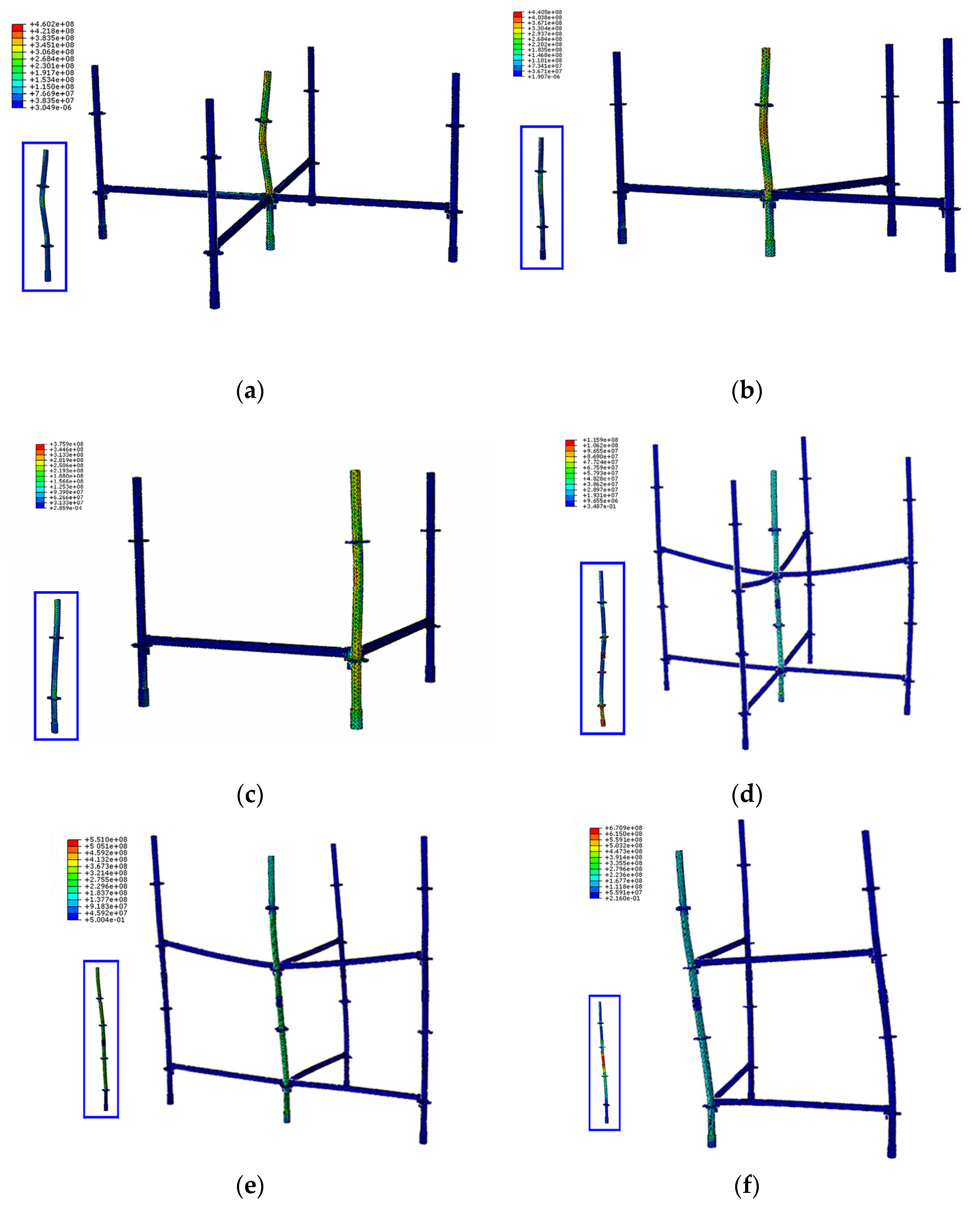
- Regarding the stress analysis, the stress concentration of the single- and double-layer vertical poles occurred in the middle of the longest free end of the vertical pole, i.e., the stress concentration was in the buckled section.
- Regarding the failure mode, according to the simulated results for the failure of the single-layer vertical poles (central, side, and corner poles), all the single-layer vertical poles of the formwork that provided support under three working conditions were unstable and damaged due to buckling of the pole, which was consistent with the failure mode of the axial compression member. However, it was still slightly different from the axial compression member. The reason was that when the pole bent, the loading point was not entirely under axial compression, therefore, a bias developed, that is, the pole underwent vertical and also horizontal displacement.
- Regarding buckling deformation, in the numerical simulation and experiment, the deformation displacement of the buckling section of the double-layer vertical pole of the new wheel coupler formwork support under three working conditions (central, side, and corner poles) was larger than that of the single-layer vertical pole. The free end was longer than the single-layer vertical pole. However, the free length included the vertical pole connecting the sleeve. When the vertical pole was connected to the sleeve, there was a gap between the sleeve and the vertical pole so that the lower vertical pole could rotate under the force. When the height of the formwork support increased, the number of connections between the vertical pole and the sleeve increased, and the accumulated deformation increased, which may have been one of the reasons that it was not conducive to the overall stability of the formwork support.
4.6. Discussion
5. Conclusions
- The eccentric tensile failure mode of the horizontal bar socket was buckling failure of the weld, and the bearing capacity was low.
- The bending failure mode of the horizontal bar was the yield strength of the horizontal bar section, which was a ductile failure. No cracks formed in the weld seam at the connection between the socket and the horizontal bar, which verified the stability of the horizontal bar of the formwork support under normal working conditions.
- According to the experimental analysis of the horizontal bar bearing capacity, the weld bearing capacity at the connection between the socket and the horizontal bar was the least among the three influencing factors. Therefore, the weak point of the bearing capacity of the horizontal bar of the formwork support was the weld seam at the connection between the socket and the horizontal bar. In practical engineering, the control of weld quality of the connection between the socket and the horizontal bar is key to ensure the bearing capacity of the horizontal bar and safe use of the formwork support.
- Buckling failure of the weld at the connection between the wheel and the vertical pole occurred under shear force, and the shear capacity of the wheel decreased obviously with decreasing number of horizontal bars connected to the wheel. The sleeve shear failure mode was buckling failure, and the connection weld did not exhibit buckling failure in the bearing process, which basically corresponded to the normal use state.
- The numerical model accurately predicted the buckling capacity of the wheel coupler formwork support over a large range. With a reduction in the number of horizontal bars connected to the vertical pole wheel disk, the stability bearing capacity showed a significant downward trend, especially with increasing layers; the stability bearing capacity decreased the most for the corner pole condition. The failure of a single-layer vertical pole was typical with lateral displacement buckling, while the double-layer vertical pole did not undergo buckling with lateral displacement.
Author Contributions
Funding
Institutional Review Board Statement
Informed Consent Statement
Data Availability Statement
Acknowledgments
Conflicts of Interest
Abbreviations
| Latin Letters | |
| Shear area | |
| D | Outer diameter size |
| Weld leg size | |
| Tensile strength design value | |
| Shear strength design value | |
| Ultimate bearing capacity of welds | |
| Ultimate shear capacity | |
| Ultimate flexural bearing capacity | |
| Measured weld length under different working conditions | |
| Calculation thickness of orthogonal fillet weld | |
| Design value of axial force | |
| Modulus of section | |
| Flexural modulus | |
| Calculated length of vertical pole | |
| Radius of gyration of cross-section | |
| Greek Letters | |
| Effective length factor | |
| Slenderness ratio | |
| Stability coefficient | |
| Others | |
| Finite element analysis | |
| Moment–rotation curve | |
References
- He, Y.; Zhang, L.; Chen, Z.; Li, C.Y. A framework of structural damage detection for civil structures using a combined multi-scale convolutional neural network and echo state network. Eng. Comput. 2022, 22, 1278–1285. [Google Scholar] [CrossRef]
- Yang, L.; Li, S. Quantitative analysis on the importance of events in construction safety accidents. China Saf. Sci. 2010, 20, 105–110. [Google Scholar] [CrossRef]
- Hui, L.; Zheng, X.; Zhang, Z. Risk analysis of high-risk operations in construction by a quantitatively improved JHA method. China Saf. Sci. 2019, 29, 146–151. [Google Scholar] [CrossRef]
- Zhang, M.; Fang, D.; Tong, R. Study on underestimating risks of scaffolders to unsafe behaviors. China Saf. Sci. 2011, 21, 145–150. [Google Scholar] [CrossRef]
- Jia, L.; Liu, H.; Chen, Z. Capacity calculation method of full hall steel tubular scaffold with couplers. Build Struct. 2016, 46, 71–76. [Google Scholar] [CrossRef]
- Liu, H.; Zhao, Q.; Wang, X. Experimental and theoretical study on stability behavior of structural steel tube and coupler scaffold without X-bracing. Eng. Struct. 2010, 32, 1003–1015. [Google Scholar] [CrossRef]
- Lu, Z. Experimental and Theoretical Study on Fastener Steel Tube Full Hall Formwork Support System. Ph.D. Thesis, Tianjin University, Tianjin, China, 2010. [Google Scholar]
- Lu, Z.; Chen, Z.; Wang, X. Experimental and theoretical study of the bearing capacity of fastener steel tube full-hall formwork support system. China Civ. Eng. 2012, 45, 49–60. [Google Scholar] [CrossRef]
- Xie, N.; Fu, X.; Wang, L.; Hu, H.; Wu, T. Design method of load and resistance factor for high falsework with couplers. KSCE J. Civ. Eng. 2016, 33, 68–75+104. [Google Scholar]
- Ding, K.; He, X. Force mechanism and progressive collapse of steel tube-coupler scaffold under local load. KSCE J. Civ. Eng. 2018, 22, 2344–2353. [Google Scholar]
- Hua, J.; Yang, Z.; Xue, X.; Huang, L.; Wang, N.; Chen, Z. Bond properties of bimetallic steel bar in seawater sea-sand concrete at different ages. Constr. Build. Mater. 2022, 323, 126539. [Google Scholar] [CrossRef]
- Yi, M.; Li, J.; Chen, Z. Structural behavior of steel tube and coupler scaffolds with stability strengthening details. Int. J. Steel Struct. 2018, 18, 79–95. [Google Scholar]
- Zhang, X. Study on the Performance of the Full Cuplock Steel Tubular Scaffoldings. Master’s Thesis, Chang’an University, Xi’an, China, 2015. [Google Scholar]
- Zhou, K. Experiment and Analysis on Load-Bearing Capacity of Steel Tubular Falsework with Bowl-Button Type Connection. Master’s Thesis, Tianjin University, Tianjin, China, 2010. [Google Scholar]
- Yang, S. The Research on Stability Bearing Capacity of Wheel Coupler Formwork Support. Master’s Thesis, Changsha University of Science & Technology, Changsha, China, 2011. [Google Scholar]
- Yang, W.; Yang, Y.; Yang, S. Experimental study on connection property of joints of pulley-clip supporting frame. Ind. Constr. 2012, 42, 101–107. [Google Scholar] [CrossRef]
- Yang, W.; Bai, S.; Zeng, K. Analysis of the anti-pull-out performance of the joint plug of the wheel-coupler steel pipe support. Constr. Saf. 2018, 33, 73–77. [Google Scholar]
- Wang, Z. The Experimental Investigation of Socket Type Steel Pipe Scaffold. Master’s Thesis, Hunan University, Changsha, China, 2013. [Google Scholar]
- Chen, M. The Study on the Popularization and Application of the Pulley-Clip High Formwork in Wenzhou. Master’s Thesis, Zhejiang University of Technology, Hangzhou, China, 2016. [Google Scholar]
- Liu, W.; Yu, H.; Wang, X. The Research on Development and Applied of the New Wheel Buckle Scaffold Support Frame. Master’s Thesis, Hebei University of Science and Technology, Shijiazhuang, China, 2018. [Google Scholar]
- Liu, W.; Yu, H.; Wang, X. Rotational stiffness experiment and numerical analysis of a new type pulley-clip scaffold. Steel Constr. 2018, 33, 26–31. [Google Scholar]
- Cheng, Y. Performance Research of Wheeled-Coupler Type Steel Tubular Scaffolding. Master’s Thesis, South China University of Technology, Guangzhou, China, 2017. [Google Scholar]
- Zhang, H. Study on Stability and Bearing Capacity of Axially Compressed Disk-Pin Joined Steel Tubular Scaffold. Master’s Thesis, Xi’an University of Architecture and Technology, Xi’an, China, 2016. [Google Scholar]
- Liu, W.; Yu, H.; Huang, J. Bearing capacity experiment and finite element analysis of pulley-clip formwork supporting frame. Build Struct. 2022, 43, 219–227. [Google Scholar]
- GB/T 228.1–2010; Metallic Materials—Tensile Experimenting. Part 1: Method of Experiment at Room Temperature. China Standards Press: Beijing, China, 2010.


| Tensile Capacity/kN | 5 | 10 | 15 | 20 | 25 | 28 | 25 | 20 |
|---|---|---|---|---|---|---|---|---|
| SJ-1 | 3.71 | 5.83 | 7.8 | 9.78 | 11.36 | 14.18 | 16.57 | 17.74 |
| SJ-2 | 3.09 | 4.86 | 6.37 | 8.54 | 10.78 | 12.69 | 14.21 | 14.88 |
| SJ-3 | 3.19 | 4.98 | 6.27 | 8.1 | 10.02 | 12.29 | 13.25 | 13.6 |
| SJ-4 | 2.37 | 4.24 | 6.59 | 8.68 | 10.57 | 13.37 | 14.42 | 14.79 |
| SJ-5 | 3.64 | 5.39 | 7.33 | 9.57 | 11.83 | 14.71 | 16.3 | 16.95 |
| Tensile Capacity/kN | 0 | 5 | 10 | 15 | 20 | 25 |
|---|---|---|---|---|---|---|
| Displacement/mm | 0 | 2.15 | 4.22 | 6.30 | 8.39 | 10.32 |
| Specimen | ZLP-1 | ZLP-2 | ZLP-3 | ZLP-4 | ZLP-5 | Average |
|---|---|---|---|---|---|---|
| Ultimate shear capacity/kN | 118.4 | 111.7 | 123.7 | 130.3 | 116.8 | 120.18 |
| Maximum displacement/mm | 5.85 | 5.31 | 6.04 | 5.48 | 5.73 | 5.68 |
| Specimen | BLP-1 | BLP-2 | BLP-3 | BLP-4 | BLP-5 | Average |
| Ultimate shear capacity/kN | 87.9 | 90.9 | 100.4 | 84.2 | 94.5 | 91.58 |
| Maximum displacement/mm | 4.03 | 4.54 | 4.82 | 3.94 | 4.46 | 4.36 |
| Specimen | JLP-1 | JLP-2 | JLP-3 | JLP-4 | JLP-5 | Average |
| Ultimate shear capacity/kN | 57.2 | 55.8 | 68.3 | 63.4 | 60.8 | 61.12 |
| Maximum displacement/mm | 5.31 | 4.53 | 5.42 | 5.3 | 4.92 | 5.10 |
| No. | Standard Distance/mm | Thickness/mm | Arc Length/mm | Outside Diameter/mm |
|---|---|---|---|---|
| SJ-1 | 50 | 3.0 | 10.48 | 47.93 |
| SJ-2 | 50 | 3.0 | 10.48 | 47.93 |
| SJ-3 | 50 | 3.0 | 10.48 | 47.93 |
| No. | Tensile Strength/MPa | Yield Strength/MPa | Elastic Modulus/MPa | Poisson’s Ratio | Elongation of Rupture/% | Area Shrinkage/% | Gauge Length after Fracture/mm |
|---|---|---|---|---|---|---|---|
| 1 | 356.98 | 245.98 | 2.01 × 10⁵ | 0.30 | 13.30 | 48.99 | 56.65 |
| 2 | 373.08 | 271.41 | 2.03 × 10⁵ | 0.31 | 11.48 | 51.73 | 55.74 |
| 3 | 356.01 | 249.16 | 2.02 × 10⁵ | 0.30 | 11.17 | 59.58 | 55.58 |
| Average value | 362.02 | 255.52 | 2.02 × 10⁵ | 0.30 | 11.98 | 53.43 | 55.99 |
| Conditions | Experiment | Error | ||||
|---|---|---|---|---|---|---|
| Stability Bearing Capacity/kN | Percentage Decrease | Stability Bearing Capacity/kN | Percentage Decrease | |||
| Single layer | Central pole | 88 | 0% | 92 | 0% | 5% |
| Side pole | 82 | 7% | 84 | 9% | 2% | |
| Corner pole | 73 | 11% | 76 | 10% | 4% | |
| Double layer | Central pole | 76 | 0% | 82 | 0% | 5% |
| Side pole | 62 | 18% | 66 | 20% | 3% | |
| Corner pole | 42 | 32% | 50 | 24% | 2% | |
Publisher’s Note: MDPI stays neutral with regard to jurisdictional claims in published maps and institutional affiliations. |
© 2022 by the authors. Licensee MDPI, Basel, Switzerland. This article is an open access article distributed under the terms and conditions of the Creative Commons Attribution (CC BY) license (https://creativecommons.org/licenses/by/4.0/).
Share and Cite
Chu, Q.; Liu, H.; Xia, S.; Dong, J.; Lei, M.; Tse, T.K.T.; Teng, L.; Li, C.Y.; Fu, Y. Numerical and Experimental Study on the Member Performance and Stability Bearing Capacity of Wheel Coupler Formwork Supports. Appl. Sci. 2022, 12, 10452. https://doi.org/10.3390/app122010452
Chu Q, Liu H, Xia S, Dong J, Lei M, Tse TKT, Teng L, Li CY, Fu Y. Numerical and Experimental Study on the Member Performance and Stability Bearing Capacity of Wheel Coupler Formwork Supports. Applied Sciences. 2022; 12(20):10452. https://doi.org/10.3390/app122010452
Chicago/Turabian StyleChu, Qi, Haiqing Liu, Shengyong Xia, Jinfeng Dong, Ming Lei, Tim K. T. Tse, Lingxiao Teng, Cruz Y. Li, and Yunfei Fu. 2022. "Numerical and Experimental Study on the Member Performance and Stability Bearing Capacity of Wheel Coupler Formwork Supports" Applied Sciences 12, no. 20: 10452. https://doi.org/10.3390/app122010452
APA StyleChu, Q., Liu, H., Xia, S., Dong, J., Lei, M., Tse, T. K. T., Teng, L., Li, C. Y., & Fu, Y. (2022). Numerical and Experimental Study on the Member Performance and Stability Bearing Capacity of Wheel Coupler Formwork Supports. Applied Sciences, 12(20), 10452. https://doi.org/10.3390/app122010452